EP4023829A1 - Swelling seal for a fire-resistant façade construction and façade construction equipped therewith - Google Patents
Swelling seal for a fire-resistant façade construction and façade construction equipped therewith Download PDFInfo
- Publication number
- EP4023829A1 EP4023829A1 EP21218483.2A EP21218483A EP4023829A1 EP 4023829 A1 EP4023829 A1 EP 4023829A1 EP 21218483 A EP21218483 A EP 21218483A EP 4023829 A1 EP4023829 A1 EP 4023829A1
- Authority
- EP
- European Patent Office
- Prior art keywords
- swelling
- strips
- façade construction
- seal
- façade
- Prior art date
- Legal status (The legal status is an assumption and is not a legal conclusion. Google has not performed a legal analysis and makes no representation as to the accuracy of the status listed.)
- Granted
Links
Images



Classifications
-
- E—FIXED CONSTRUCTIONS
- E04—BUILDING
- E04B—GENERAL BUILDING CONSTRUCTIONS; WALLS, e.g. PARTITIONS; ROOFS; FLOORS; CEILINGS; INSULATION OR OTHER PROTECTION OF BUILDINGS
- E04B2/00—Walls, e.g. partitions, for buildings; Wall construction with regard to insulation; Connections specially adapted to walls
- E04B2/88—Curtain walls
- E04B2/96—Curtain walls comprising panels attached to the structure through mullions or transoms
- E04B2/967—Details of the cross-section of the mullions or transoms
-
- E—FIXED CONSTRUCTIONS
- E04—BUILDING
- E04B—GENERAL BUILDING CONSTRUCTIONS; WALLS, e.g. PARTITIONS; ROOFS; FLOORS; CEILINGS; INSULATION OR OTHER PROTECTION OF BUILDINGS
- E04B1/00—Constructions in general; Structures which are not restricted either to walls, e.g. partitions, or floors or ceilings or roofs
- E04B1/62—Insulation or other protection; Elements or use of specified material therefor
- E04B1/92—Protection against other undesired influences or dangers
- E04B1/94—Protection against other undesired influences or dangers against fire
-
- E—FIXED CONSTRUCTIONS
- E04—BUILDING
- E04B—GENERAL BUILDING CONSTRUCTIONS; WALLS, e.g. PARTITIONS; ROOFS; FLOORS; CEILINGS; INSULATION OR OTHER PROTECTION OF BUILDINGS
- E04B1/00—Constructions in general; Structures which are not restricted either to walls, e.g. partitions, or floors or ceilings or roofs
- E04B1/62—Insulation or other protection; Elements or use of specified material therefor
- E04B1/66—Sealings
- E04B1/68—Sealings of joints, e.g. expansion joints
- E04B2001/6818—Joints with swellable parts
Definitions
- the present invention relates to a swelling seal for a fire-resistant façade construction.
- the invention relates to a façade construction of the curtain wall type.
- curtain walls are known and built around a skeleton of profiles made from aluminium or the like in the form of mullions and transoms which form adjoining frames for façade panels, typically glass panels.
- the front sides of the mullions and transoms facing the outside of the façade construction are provided with an open screw channel delimited by two parallel protruding ribs of the profiles which define a rebate in which the panels are wedged with a certain play by means of glazing bead supports.
- the panels are clamped along the edges against the aforementioned front sides of the mullions and transoms by means of screws which are screwed in the aforementioned screw channels through an insulation profile made from thermal insulation material which has been pushed into the screw channel in advance with an insert edge.
- Said swelling seals are made of a material which in the event of a fire will swell up under the influence of the heat, with the intention of filling the space around the panels thereby preventing hot air from flowing to the nonburning side such that the flames are at least temporarily prevented from flashing over and no oxygen is supplied to the burning side which could fan the fire.
- said swelling seals are glued separately on the aluminium profiles when building the façade construction, typically on either side of the ribs defining the screw channel.
- Another disadvantage is that when applying the swelling seals at low temperatures and damp weather a bad adhesion of the glue is obtained and glueing in adverse weather conditions is thus not recommended.
- the purpose of the present invention is to provide a solution to one or more of the aforementioned and other disadvantages.
- the invention relates to a swelling seal for a fire-resistant façade construction, containing two swelling strips made from a material which in the event of a fire swell up under the influence of heat, characterised in that the swelling strips are interconnected by at least one spacer which holds the swelling strips at a distance from each other and preferably essentially parallel to each other.
- the swelling seal according to the invention is slid over the ribs of the screw channel with the swelling strips on either sides of the ribs of the screw channel.
- the swelling seal is kept in place by the insulation profile and the screws in the screw channel.
- the advantage is that the swelling seal does not necessarily have to be glued.
- the strips can be applied in all weather conditions, even in cold and damp weather.
- the swelling seal is made as an extruded profile or a co-extruded profile if the spacer is made from another material than that of the swelling strips, for example from synthetic material.
- the spacer of the swelling seal contains a U-shaped profiled section with legs which run essentially parallel with the swelling strips, whereby the form and the dimensions of said U-shaped section are preferably such that upon mounting the swelling seal it fittingly slides in the screw channel.
- the swelling seal is first slid over said insert edge of the insulation profile with the U-shaped section, after which the assembly can be slid as a whole into the screw channel of the façade profile, such that the swelling seal is affixed.
- Said type of swelling seal makes it easy to also use insulating parts (Hi-foam) in combination with a swelling seal.
- the invention also relates to a façade construction in the form of a curtain wall which is provided with swelling seals according to the invention.
- Figure 1 shows the skeleton of a façadeconstruction 1 according to the invention which is constructed from mullions 2 and transoms 3 in the form of profiles made from aluminium or the like.
- the front sides of the profiles 2 and 3 facing the outside 4 of the façade construction 5 are provided with an open screw channel 6 that is delimited by two parallel protruding ribs 7 of the profiles 2 and 3 which define a rebate 8 in which, as shown in figure 4 , glass or other panels 9 are attached with a certain play S by means of clamping profiles 10 which clamp the edges of the panels 9 between seals 11 on the front side 5 of the profiles and the underside of the clamping profiles 10.
- the clamping profiles 10 are screwed against the panels 9 by means of screws 12 which are screwed in the screw channels 6 through insulation profiles 13 made from insulation foam or the like which are enclosed in the screw channels 6 in the known way with a longitudinal insert edge 14.
- the clamping profiles 10 and screws 12 are covered by means of finishing profiles 15 which are snapped onto the clamping profiles 10.
- the façadeconstruction 1 is made with swelling seals 16 according to the invention which are made with two parallel tape-shaped swelling strips 17 made from a material which in the event of a fire swell up under the influence of heat.
- swelling strips 17 are interconnected by at least one spacer 18 made from synthetic material or the like which interconnects the swelling strips 17 and holds them at a distance A from each other which is essentially equal to the breadth B measured between the outsides of the two ribs 7.
- the spacer 18 contains a U-shaped profiled section 19 with legs 20 which run essentially parallel with the swelling strips 17 at a distance from the swelling strips 17 equal to the breadth B' of the ribs 7 and which at their free end are each connected with a swelling strip 17 by means of a cross member 21 at a distance from both longitudinal edges 22 of the swelling strips 17, respectively at a distance C and D.
- the form and dimensions of the swelling seals 16 are such that the swelling seals 16 can be fittingly slid over the ribs 7 with the U-shaped section 19 in the screw channels 6 with the opening to the outside 4 of the façadeconstruction 1 and the swelling strips 17 fittingly over the outside of the ribs 7 and over the entire or practically entire length E of the ribs 7.
- the swelling seal 16 is thereby first slid with the U-shaped section 19 over said insert edge 14 of the insulation profile 13 for example, after which the assembly can be slid as a whole into a screw channel 6 of the profiles 2 and 3, such that the swelling seal is affixed as shown in the figures 2 and 3 .
- the spacer 18 may be made from another material than the swelling strips 17, in which case the swelling seals 16 may, for example, be co-extruded.
- the entire swelling seal 16 is made from the same material by extrusion or the like.
- the swelling strips are glued or co-extruded on a slat-shaped support made from synthetic material or the like which analogously as above are interconnected by a spacer.
- the support and spacer can also be obtained by injection moulding, for example, and the spacer can also be interrupted lengthways of the swelling seal.
- the insulation profiles 13 show a beamshaped body 23, the breadth of which is approximately equal to the breadth on the outside of the ribs 7 of the screw channels 6 and which over a certain length fits on the side of the insert edge 14 between the swelling strips 17.
- the swelling strips 17 overlap the body 23 over a said distance D and the body 23 protrudes with a section with length F from the swelling seal 16, whereby said section is or can be surrounded by insulating parts 24 with laterally projecting wings 25 from high-grade thermal insulation foam.
- figures 5 and 6 show the situation for the mullions 2 with a swelling seal 16 and insulation profile 13 with essentially the same properties as aforementioned but a slightly deviating form and dimensions.
Landscapes
- Engineering & Computer Science (AREA)
- Architecture (AREA)
- Physics & Mathematics (AREA)
- Electromagnetism (AREA)
- Civil Engineering (AREA)
- Structural Engineering (AREA)
- Building Environments (AREA)
- Load-Bearing And Curtain Walls (AREA)
Abstract
Description
- The present invention relates to a swelling seal for a fire-resistant façade construction.
- In particular the invention relates to a façade construction of the curtain wall type.
- Such curtain walls are known and built around a skeleton of profiles made from aluminium or the like in the form of mullions and transoms which form adjoining frames for façade panels, typically glass panels.
- To this end, the front sides of the mullions and transoms facing the outside of the façade construction are provided with an open screw channel delimited by two parallel protruding ribs of the profiles which define a rebate in which the panels are wedged with a certain play by means of glazing bead supports.
- Using clamping profiles on the outside of the façade, the panels are clamped along the edges against the aforementioned front sides of the mullions and transoms by means of screws which are screwed in the aforementioned screw channels through an insulation profile made from thermal insulation material which has been pushed into the screw channel in advance with an insert edge.
- It is known to apply swelling seals in the form of slatshaped swelling strips in the rebate, more specifically in the space between the panels and the screw channels.
- Said swelling seals are made of a material which in the event of a fire will swell up under the influence of the heat, with the intention of filling the space around the panels thereby preventing hot air from flowing to the nonburning side such that the flames are at least temporarily prevented from flashing over and no oxygen is supplied to the burning side which could fan the fire.
- Traditionally, said swelling seals are glued separately on the aluminium profiles when building the façade construction, typically on either side of the ribs defining the screw channel.
- This has the disadvantage that the surfaces where the swelling seals need to be glued need to be properly cleaned and degreased.
- Another disadvantage is that when applying the swelling seals at low temperatures and damp weather a bad adhesion of the glue is obtained and glueing in adverse weather conditions is thus not recommended.
- Consequently this becomes time-consuming.
- Furthermore, if the glued swelling seals come loose before the panels are mounted, this makes mounting the panels more difficult.
- The purpose of the present invention is to provide a solution to one or more of the aforementioned and other disadvantages.
- To this end, the invention relates to a swelling seal for a fire-resistant façade construction, containing two swelling strips made from a material which in the event of a fire swell up under the influence of heat, characterised in that the swelling strips are interconnected by at least one spacer which holds the swelling strips at a distance from each other and preferably essentially parallel to each other.
- Upon building the façade construction, the swelling seal according to the invention is slid over the ribs of the screw channel with the swelling strips on either sides of the ribs of the screw channel.
- After mounting the glass panels, the swelling seal is kept in place by the insulation profile and the screws in the screw channel.
- The advantage is that the swelling seal does not necessarily have to be glued.
- Consequently it is also not necessary to clean and degrease the surfaces of the ribs and the swelling strips can be applied very quickly and without special tools or glue.
- Furthermore, the strips can be applied in all weather conditions, even in cold and damp weather.
- Preferably, the swelling seal is made as an extruded profile or a co-extruded profile if the spacer is made from another material than that of the swelling strips, for example from synthetic material.
- Preferably, the spacer of the swelling seal contains a U-shaped profiled section with legs which run essentially parallel with the swelling strips, whereby the form and the dimensions of said U-shaped section are preferably such that upon mounting the swelling seal it fittingly slides in the screw channel.
- Upon mounting, the swelling seal is first slid over said insert edge of the insulation profile with the U-shaped section, after which the assembly can be slid as a whole into the screw channel of the façade profile, such that the swelling seal is affixed.
- Said type of swelling seal makes it easy to also use insulating parts (Hi-foam) in combination with a swelling seal.
- The invention also relates to a façade construction in the form of a curtain wall which is provided with swelling seals according to the invention.
- With the intention of better showing the characteristics of the invention, a few preferred embodiments of a swelling seal according to the invention and a facade construction equipped with it are described by way of an example without any limiting nature, with reference to the accompanying drawings, wherein:
-
figure 1 schematically shows a perspective view of a section of a façade construction according to the invention in exploded view; -
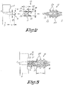
figure 2 shows a cross-section according to line II-II infigure 1 on a larger scale; -
figure 3 shows the cross-section offigure 2 but in assembled condition; -
figure 4 shows a cross-section as that offigure 3 but for an assembled façade construction; -
figure 5 shows a cross-section according to line V-V infigure 1 on a larger scale; -
figure 6 shows the cross-section offigure 5 but in assembled condition. -
Figure 1 shows the skeleton of a façadeconstruction 1 according to the invention which is constructed frommullions 2 andtransoms 3 in the form of profiles made from aluminium or the like. - The front sides of the
profiles outside 4 of thefaçade construction 5 are provided with anopen screw channel 6 that is delimited by two parallel protruding ribs 7 of theprofiles rebate 8 in which, as shown infigure 4 , glass or other panels 9 are attached with a certain play S by means ofclamping profiles 10 which clamp the edges of the panels 9 betweenseals 11 on thefront side 5 of the profiles and the underside of theclamping profiles 10. - The
clamping profiles 10 are screwed against the panels 9 by means ofscrews 12 which are screwed in thescrew channels 6 throughinsulation profiles 13 made from insulation foam or the like which are enclosed in thescrew channels 6 in the known way with alongitudinal insert edge 14. - The
clamping profiles 10 andscrews 12 are covered by means offinishing profiles 15 which are snapped onto theclamping profiles 10. - The façadeconstruction 1 is made with
swelling seals 16 according to the invention which are made with two parallel tape-shaped swelling strips 17 made from a material which in the event of a fire swell up under the influence of heat. - As shown in the
figures 2 to 4 for thetransoms 3,swelling strips 17 are interconnected by at least onespacer 18 made from synthetic material or the like which interconnects theswelling strips 17 and holds them at a distance A from each other which is essentially equal to the breadth B measured between the outsides of the two ribs 7. - The
spacer 18 contains a U-shaped profiledsection 19 withlegs 20 which run essentially parallel with theswelling strips 17 at a distance from theswelling strips 17 equal to the breadth B' of the ribs 7 and which at their free end are each connected with aswelling strip 17 by means of across member 21 at a distance from bothlongitudinal edges 22 of theswelling strips 17, respectively at a distance C and D. - In the example, the form and dimensions of the
swelling seals 16 are such that theswelling seals 16 can be fittingly slid over the ribs 7 with the U-shapedsection 19 in thescrew channels 6 with the opening to the outside 4 of the façadeconstruction 1 and theswelling strips 17 fittingly over the outside of the ribs 7 and over the entire or practically entire length E of the ribs 7. - The
swelling seal 16 is thereby first slid with the U-shapedsection 19 over saidinsert edge 14 of theinsulation profile 13 for example, after which the assembly can be slid as a whole into ascrew channel 6 of theprofiles figures 2 and 3 . - The
spacer 18 may be made from another material than theswelling strips 17, in which case theswelling seals 16 may, for example, be co-extruded. - However, it is not excluded that the
entire swelling seal 16 is made from the same material by extrusion or the like. - It is also not excluded that the swelling strips are glued or co-extruded on a slat-shaped support made from synthetic material or the like which analogously as above are interconnected by a spacer. The support and spacer can also be obtained by injection moulding, for example, and the spacer can also be interrupted lengthways of the swelling seal.
- In
figures 2 and 3 , theinsulation profiles 13 show abeamshaped body 23, the breadth of which is approximately equal to the breadth on the outside of the ribs 7 of thescrew channels 6 and which over a certain length fits on the side of theinsert edge 14 between theswelling strips 17. - In a mounted condition the
swelling strips 17 overlap thebody 23 over a said distance D and thebody 23 protrudes with a section with length F from theswelling seal 16, whereby said section is or can be surrounded byinsulating parts 24 with laterally projectingwings 25 from high-grade thermal insulation foam. - Analogously as for the transoms,
figures 5 and 6 show the situation for themullions 2 with aswelling seal 16 andinsulation profile 13 with essentially the same properties as aforementioned but a slightly deviating form and dimensions. - The present invention is by no means limited to the embodiments described as an example and shown in the drawings, but a swelling seal according to the invention can be realised in all kinds of forms and dimensions, without departing from the scope of the invention.
Claims (14)
- Swelling seal for a fire-resistant façade construction, containing two swelling strips (17) made of a material which in the event of a fire swell up under the influence of heat, characterised in that the swelling strips (17) are interconnected by at least one spacer (18) which holds the swelling strips (17) at a distance (A) from each other.
- Swelling seal according to claim 1, characterised in that the swelling seal (16) is made as an extruded profile or a co-extruded profile.
- Swelling seal according to claim 1 or 2, characterised in that the swelling strips (17) are essentially parallel to each other.
- Swelling seal according to any one of the previous claims, characterised in that the spacer (18) contains a U-shaped profiled section (19) with legs (20) that run parallel with the swelling strips (17).
- Swelling seal according to claim 4, characterised in that the legs (20) of the U-shaped profiled section (19) are located at the distance (B') from the swelling strips (17) .
- Swelling seal according to claim 5, characterised in that the legs of the U-shaped profiled section (19) are connected with their free ends with the swelling strips (17) by means of a cross member (21) of the spacer (18).
- Swelling seal according to claim 6, characterised in that the cross members (1) are connected with the swelling strips (17) at a distance (C, D) from the longitudinal edges (22) of the swelling strips (17).
- Façade construction, containing a skeleton of profiles made from aluminium or the like in the form of mullions (2) and transoms (3) of adjoining frames for façade panels (9) and which on their front sides (5) facing the outside of the façade construction (1) are provided with an open screw channel (6) delimited by two parallel protruding ribs (7) of the profiles which define a rebate (8) in which the panels (9) are attached with a certain lateral play by means of clamping profiles (10) which cover the edges of the panels (9) and which are clamped against said front sides (5) of the mullions (2) and transoms (3) by means of screws (12) which are screwed in said screw channels (6), characterised in that the façade construction (1) is provided with swelling seals (16) according to any one of the previous claims whereby the swelling seals (16) are fittingly slid over the screw channels (6) of the mullions (2) and transoms (3) with their swelling strips (17) on either side of the screw channels (6).
- Façade construction according to claim 8 and one of the claims 4 to 7, characterised in that the swelling seals (16) are fittingly slid with their U-shaped section (19) in the screw channels (6) with the opening of the U-shaped section (19) oriented toward the outside (4) of the façade construction (1).
- Façade construction according to claim 9, characterised in that between the screw channels (6) and the clamping profiles (10) an insulation profile (13) is provided which is made of thermal insulation foam or another insulation material and is fittingly slid with an insert edge (14) in the U-shaped section (19) of the swelling seal (16) up into the screw channel (6).
- Façade construction according to claim 10, characterised in that said screws (12) are screwed through the insulation profiles (13) in screw channels (6).
- Façade construction according to claim 10 or 11, characterised in that the insulation profiles (13) relative to the insert edge (14) show a wider body (23), the breadth of which is approximately equal to the breadth (B) on the outside of the ribs (7) of the screw channels (6).
- Façade construction according to claim 12, characterised in that the swelling seal (16) extends with the swelling strips (17) over a certain length (D) of said body (23) of the insulation profile (13).
- Façade construction according to claim 12 or 13, characterised in that the body (23) extends outwardly with a certain length (F) from the swelling seal (16), said section being surrounded by insulating parts (24) with one or more laterally projecting wings (25) made from thermal insulation material.
Applications Claiming Priority (1)
| Application Number | Priority Date | Filing Date | Title |
|---|---|---|---|
| BE20215003A BE1028989B1 (en) | 2021-01-05 | 2021-01-05 | Swell sealing for a fire-resistant facade construction and facade construction equipped with it |
Publications (3)
| Publication Number | Publication Date |
|---|---|
| EP4023829A1 true EP4023829A1 (en) | 2022-07-06 |
| EP4023829C0 EP4023829C0 (en) | 2025-04-30 |
| EP4023829B1 EP4023829B1 (en) | 2025-04-30 |
Family
ID=74186378
Family Applications (1)
| Application Number | Title | Priority Date | Filing Date |
|---|---|---|---|
| EP21218483.2A Active EP4023829B1 (en) | 2021-01-05 | 2021-12-31 | Swelling seal for a fire-resistant façade construction and façade construction equipped therewith |
Country Status (3)
| Country | Link |
|---|---|
| EP (1) | EP4023829B1 (en) |
| BE (1) | BE1028989B1 (en) |
| PL (1) | PL4023829T3 (en) |
Cited By (2)
| Publication number | Priority date | Publication date | Assignee | Title |
|---|---|---|---|---|
| DE102022117885A1 (en) * | 2022-07-18 | 2024-01-18 | HUECK System GmbH & Co. KG | FACADE OR LIGHT ROOF WITH A BEAM OR POST PROFILE |
| EP4711547A1 (en) * | 2024-09-12 | 2026-03-18 | Hydro Extruded Solutions As | Fire-resistant insert for the assembly shock in the separation area of two adjacent posts of a post-crossbar construction |
Citations (4)
| Publication number | Priority date | Publication date | Assignee | Title |
|---|---|---|---|---|
| DE202006004165U1 (en) * | 2006-03-16 | 2007-04-19 | Henkenjohann, Johann | Insulator for an existing post / transom facade construction |
| DE102007053659A1 (en) * | 2007-11-08 | 2009-05-20 | Hermann Gutmann Werke Ag | Building facade for acting as a fire-protection facade has a framed structure made from uprights and bars as well as from glazing elements/cladding enclosed by the uprights and bars |
| WO2015189348A1 (en) * | 2014-06-12 | 2015-12-17 | Ensinger Gmbh | Thermally insulating spacer profile |
| EP3034709A1 (en) * | 2014-12-17 | 2016-06-22 | HILTI Aktiengesellschaft | Façade module, building structure and method for installing the façade module |
-
2021
- 2021-01-05 BE BE20215003A patent/BE1028989B1/en active IP Right Grant
- 2021-12-31 EP EP21218483.2A patent/EP4023829B1/en active Active
- 2021-12-31 PL PL21218483.2T patent/PL4023829T3/en unknown
Patent Citations (4)
| Publication number | Priority date | Publication date | Assignee | Title |
|---|---|---|---|---|
| DE202006004165U1 (en) * | 2006-03-16 | 2007-04-19 | Henkenjohann, Johann | Insulator for an existing post / transom facade construction |
| DE102007053659A1 (en) * | 2007-11-08 | 2009-05-20 | Hermann Gutmann Werke Ag | Building facade for acting as a fire-protection facade has a framed structure made from uprights and bars as well as from glazing elements/cladding enclosed by the uprights and bars |
| WO2015189348A1 (en) * | 2014-06-12 | 2015-12-17 | Ensinger Gmbh | Thermally insulating spacer profile |
| EP3034709A1 (en) * | 2014-12-17 | 2016-06-22 | HILTI Aktiengesellschaft | Façade module, building structure and method for installing the façade module |
Cited By (3)
| Publication number | Priority date | Publication date | Assignee | Title |
|---|---|---|---|---|
| DE102022117885A1 (en) * | 2022-07-18 | 2024-01-18 | HUECK System GmbH & Co. KG | FACADE OR LIGHT ROOF WITH A BEAM OR POST PROFILE |
| EP4310267A1 (en) * | 2022-07-18 | 2024-01-24 | HUECK System GmbH & Co. KG | Facade or skylight with a mullion or transom profile |
| EP4711547A1 (en) * | 2024-09-12 | 2026-03-18 | Hydro Extruded Solutions As | Fire-resistant insert for the assembly shock in the separation area of two adjacent posts of a post-crossbar construction |
Also Published As
| Publication number | Publication date |
|---|---|
| EP4023829C0 (en) | 2025-04-30 |
| EP4023829B1 (en) | 2025-04-30 |
| BE1028989B1 (en) | 2022-08-10 |
| BE1028989A1 (en) | 2022-08-01 |
| PL4023829T3 (en) | 2025-09-08 |
Similar Documents
| Publication | Publication Date | Title |
|---|---|---|
| EP0102825B1 (en) | Demountable partitioning system | |
| EP4023829B1 (en) | Swelling seal for a fire-resistant façade construction and façade construction equipped therewith | |
| EP2318634B1 (en) | Sealing membrane for sealing gaps between frames of a window and rough openings | |
| US8997412B1 (en) | Combination marine and stop frame glazed panel | |
| US20150267460A1 (en) | Combination Marine and Stop Frame Glazed Panel and Method for the Same | |
| SE469800B (en) | Door leaf Profile | |
| US11293212B2 (en) | Door assemblies with insulated glazing unit venting | |
| US4799332A (en) | Sliding window | |
| KR102727587B1 (en) | Frames for facades, facade elements, windows or doors | |
| EP1177364A4 (en) | Integrated multipane window unit and sash assembly and method for manufacturing the same | |
| EA013047B1 (en) | Constituent element | |
| US5950380A (en) | Bullet resistant window assembly | |
| ES2963337T3 (en) | Mullions, transoms and window and curtain wall systems | |
| US10648226B2 (en) | Main-frame bar and/or wing-frame bar, and door, window, or façade element | |
| GB2142357A (en) | Curtain wall assembly | |
| WO1997018365A1 (en) | Panel sealing structure | |
| HUP9904612A2 (en) | Heat insulating spacer for insulated glazing | |
| US6185882B1 (en) | Bullet resistant window assembly | |
| RU2125640C1 (en) | Plastic framed profile with sealing interlayer | |
| HU176449B (en) | Hollow profile frame particularly for doors,windows and similar opening closing devices | |
| US4471597A (en) | Extruded plastic window framing | |
| EP0797711A1 (en) | A device in a profile-member system | |
| RU2658814C1 (en) | Balconies post-bar glazing insulation system and its installation method | |
| AU2011101215A4 (en) | Secondary Glazing System | |
| RU202526U1 (en) | PROFILE FOR FACADE AND WINDOW CONSTRUCTIONS |
Legal Events
| Date | Code | Title | Description |
|---|---|---|---|
| PUAI | Public reference made under article 153(3) epc to a published international application that has entered the european phase |
Free format text: ORIGINAL CODE: 0009012 |
|
| STAA | Information on the status of an ep patent application or granted ep patent |
Free format text: STATUS: THE APPLICATION HAS BEEN PUBLISHED |
|
| AK | Designated contracting states |
Kind code of ref document: A1 Designated state(s): AL AT BE BG CH CY CZ DE DK EE ES FI FR GB GR HR HU IE IS IT LI LT LU LV MC MK MT NL NO PL PT RO RS SE SI SK SM TR |
|
| STAA | Information on the status of an ep patent application or granted ep patent |
Free format text: STATUS: REQUEST FOR EXAMINATION WAS MADE |
|
| 17P | Request for examination filed |
Effective date: 20221004 |
|
| RBV | Designated contracting states (corrected) |
Designated state(s): AL AT BE BG CH CY CZ DE DK EE ES FI FR GB GR HR HU IE IS IT LI LT LU LV MC MK MT NL NO PL PT RO RS SE SI SK SM TR |
|
| GRAP | Despatch of communication of intention to grant a patent |
Free format text: ORIGINAL CODE: EPIDOSNIGR1 |
|
| STAA | Information on the status of an ep patent application or granted ep patent |
Free format text: STATUS: GRANT OF PATENT IS INTENDED |
|
| RIC1 | Information provided on ipc code assigned before grant |
Ipc: E04B 1/94 20060101ALN20250115BHEP Ipc: E04B 1/68 20060101ALN20250115BHEP Ipc: E04B 2/96 20060101AFI20250115BHEP |
|
| INTG | Intention to grant announced |
Effective date: 20250131 |
|
| GRAS | Grant fee paid |
Free format text: ORIGINAL CODE: EPIDOSNIGR3 |
|
| GRAA | (expected) grant |
Free format text: ORIGINAL CODE: 0009210 |
|
| STAA | Information on the status of an ep patent application or granted ep patent |
Free format text: STATUS: THE PATENT HAS BEEN GRANTED |
|
| AK | Designated contracting states |
Kind code of ref document: B1 Designated state(s): AL AT BE BG CH CY CZ DE DK EE ES FI FR GB GR HR HU IE IS IT LI LT LU LV MC MK MT NL NO PL PT RO RS SE SI SK SM TR |
|
| REG | Reference to a national code |
Ref country code: CH Ref legal event code: EP Ref country code: GB Ref legal event code: FG4D |
|
| REG | Reference to a national code |
Ref country code: IE Ref legal event code: FG4D |
|
| U01 | Request for unitary effect filed |
Effective date: 20250506 |
|
| U07 | Unitary effect registered |
Designated state(s): AT BE BG DE DK EE FI FR IT LT LU LV MT NL PT RO SE SI Effective date: 20250512 |
|
| PG25 | Lapsed in a contracting state [announced via postgrant information from national office to epo] |
Ref country code: ES Free format text: LAPSE BECAUSE OF FAILURE TO SUBMIT A TRANSLATION OF THE DESCRIPTION OR TO PAY THE FEE WITHIN THE PRESCRIBED TIME-LIMIT Effective date: 20250430 |
|
| PG25 | Lapsed in a contracting state [announced via postgrant information from national office to epo] |
Ref country code: NO Free format text: LAPSE BECAUSE OF FAILURE TO SUBMIT A TRANSLATION OF THE DESCRIPTION OR TO PAY THE FEE WITHIN THE PRESCRIBED TIME-LIMIT Effective date: 20250730 Ref country code: GR Free format text: LAPSE BECAUSE OF FAILURE TO SUBMIT A TRANSLATION OF THE DESCRIPTION OR TO PAY THE FEE WITHIN THE PRESCRIBED TIME-LIMIT Effective date: 20250731 |
|
| PG25 | Lapsed in a contracting state [announced via postgrant information from national office to epo] |
Ref country code: HR Free format text: LAPSE BECAUSE OF FAILURE TO SUBMIT A TRANSLATION OF THE DESCRIPTION OR TO PAY THE FEE WITHIN THE PRESCRIBED TIME-LIMIT Effective date: 20250430 |
|
| PG25 | Lapsed in a contracting state [announced via postgrant information from national office to epo] |
Ref country code: RS Free format text: LAPSE BECAUSE OF FAILURE TO SUBMIT A TRANSLATION OF THE DESCRIPTION OR TO PAY THE FEE WITHIN THE PRESCRIBED TIME-LIMIT Effective date: 20250731 |
|
| PG25 | Lapsed in a contracting state [announced via postgrant information from national office to epo] |
Ref country code: IS Free format text: LAPSE BECAUSE OF FAILURE TO SUBMIT A TRANSLATION OF THE DESCRIPTION OR TO PAY THE FEE WITHIN THE PRESCRIBED TIME-LIMIT Effective date: 20250830 |
|
| REG | Reference to a national code |
Ref country code: CH Ref legal event code: U11 Free format text: ST27 STATUS EVENT CODE: U-0-0-U10-U11 (AS PROVIDED BY THE NATIONAL OFFICE) Effective date: 20260101 |
|
| PGFP | Annual fee paid to national office [announced via postgrant information from national office to epo] |
Ref country code: GB Payment date: 20251218 Year of fee payment: 5 |
|
| PG25 | Lapsed in a contracting state [announced via postgrant information from national office to epo] |
Ref country code: SM Free format text: LAPSE BECAUSE OF FAILURE TO SUBMIT A TRANSLATION OF THE DESCRIPTION OR TO PAY THE FEE WITHIN THE PRESCRIBED TIME-LIMIT Effective date: 20250430 |
|
| PG25 | Lapsed in a contracting state [announced via postgrant information from national office to epo] |
Ref country code: CZ Free format text: LAPSE BECAUSE OF FAILURE TO SUBMIT A TRANSLATION OF THE DESCRIPTION OR TO PAY THE FEE WITHIN THE PRESCRIBED TIME-LIMIT Effective date: 20250430 |
|
| PGFP | Annual fee paid to national office [announced via postgrant information from national office to epo] |
Ref country code: IE Payment date: 20251218 Year of fee payment: 5 |
|
| PGFP | Annual fee paid to national office [announced via postgrant information from national office to epo] |
Ref country code: PL Payment date: 20251219 Year of fee payment: 5 |
|
| PG25 | Lapsed in a contracting state [announced via postgrant information from national office to epo] |
Ref country code: SK Free format text: LAPSE BECAUSE OF FAILURE TO SUBMIT A TRANSLATION OF THE DESCRIPTION OR TO PAY THE FEE WITHIN THE PRESCRIBED TIME-LIMIT Effective date: 20250430 |
|
| U20 | Renewal fee for the european patent with unitary effect paid |
Year of fee payment: 5 Effective date: 20251222 |
|
| PLBE | No opposition filed within time limit |
Free format text: ORIGINAL CODE: 0009261 |
|
| STAA | Information on the status of an ep patent application or granted ep patent |
Free format text: STATUS: NO OPPOSITION FILED WITHIN TIME LIMIT |
|
| REG | Reference to a national code |
Ref country code: CH Ref legal event code: L10 Free format text: ST27 STATUS EVENT CODE: U-0-0-L10-L00 (AS PROVIDED BY THE NATIONAL OFFICE) Effective date: 20260311 |
|
| 26N | No opposition filed |
Effective date: 20260202 |
|
| PGFP | Annual fee paid to national office [announced via postgrant information from national office to epo] |
Ref country code: CH Payment date: 20260101 Year of fee payment: 5 |
|
| PG25 | Lapsed in a contracting state [announced via postgrant information from national office to epo] |
Ref country code: MC Free format text: LAPSE BECAUSE OF FAILURE TO SUBMIT A TRANSLATION OF THE DESCRIPTION OR TO PAY THE FEE WITHIN THE PRESCRIBED TIME-LIMIT Effective date: 20250430 |