EP4023536A2 - Roof assembly for a vehicle, and vehicle comprising such roof assembly - Google Patents
Roof assembly for a vehicle, and vehicle comprising such roof assembly Download PDFInfo
- Publication number
- EP4023536A2 EP4023536A2 EP21216967.6A EP21216967A EP4023536A2 EP 4023536 A2 EP4023536 A2 EP 4023536A2 EP 21216967 A EP21216967 A EP 21216967A EP 4023536 A2 EP4023536 A2 EP 4023536A2
- Authority
- EP
- European Patent Office
- Prior art keywords
- frame
- vehicle
- panel
- partly
- reinforcement
- Prior art date
- Legal status (The legal status is an assumption and is not a legal conclusion. Google has not performed a legal analysis and makes no representation as to the accuracy of the status listed.)
- Granted
Links
Images







Classifications
-
- B—PERFORMING OPERATIONS; TRANSPORTING
- B62—LAND VEHICLES FOR TRAVELLING OTHERWISE THAN ON RAILS
- B62D—MOTOR VEHICLES; TRAILERS
- B62D25/00—Superstructure or monocoque structure sub-units; Parts or details thereof not otherwise provided for
- B62D25/06—Fixed roofs
-
- B—PERFORMING OPERATIONS; TRANSPORTING
- B60—VEHICLES IN GENERAL
- B60J—WINDOWS, WINDSCREENS, NON-FIXED ROOFS, DOORS, OR SIMILAR DEVICES FOR VEHICLES; REMOVABLE EXTERNAL PROTECTIVE COVERINGS SPECIALLY ADAPTED FOR VEHICLES
- B60J7/00—Non-fixed roofs; Roofs with movable panels, e.g. rotary sunroofs
- B60J7/08—Non-fixed roofs; Roofs with movable panels, e.g. rotary sunroofs of non-sliding type, i.e. movable or removable roofs or panels, e.g. let-down tops or roofs capable of being easily detached or of assuming a collapsed or inoperative position
- B60J7/16—Non-fixed roofs; Roofs with movable panels, e.g. rotary sunroofs of non-sliding type, i.e. movable or removable roofs or panels, e.g. let-down tops or roofs capable of being easily detached or of assuming a collapsed or inoperative position non-foldable and rigid, e.g. a one-piece hard-top or a single rigid roof panel
- B60J7/1628—Non-fixed roofs; Roofs with movable panels, e.g. rotary sunroofs of non-sliding type, i.e. movable or removable roofs or panels, e.g. let-down tops or roofs capable of being easily detached or of assuming a collapsed or inoperative position non-foldable and rigid, e.g. a one-piece hard-top or a single rigid roof panel for covering the passenger compartment
- B60J7/1635—Non-fixed roofs; Roofs with movable panels, e.g. rotary sunroofs of non-sliding type, i.e. movable or removable roofs or panels, e.g. let-down tops or roofs capable of being easily detached or of assuming a collapsed or inoperative position non-foldable and rigid, e.g. a one-piece hard-top or a single rigid roof panel for covering the passenger compartment of non-convertible vehicles
- B60J7/1657—Non-fixed roofs; Roofs with movable panels, e.g. rotary sunroofs of non-sliding type, i.e. movable or removable roofs or panels, e.g. let-down tops or roofs capable of being easily detached or of assuming a collapsed or inoperative position non-foldable and rigid, e.g. a one-piece hard-top or a single rigid roof panel for covering the passenger compartment of non-convertible vehicles at least a major part of the roof pivoting about a stationary axis
-
- B—PERFORMING OPERATIONS; TRANSPORTING
- B60—VEHICLES IN GENERAL
- B60J—WINDOWS, WINDSCREENS, NON-FIXED ROOFS, DOORS, OR SIMILAR DEVICES FOR VEHICLES; REMOVABLE EXTERNAL PROTECTIVE COVERINGS SPECIALLY ADAPTED FOR VEHICLES
- B60J7/00—Non-fixed roofs; Roofs with movable panels, e.g. rotary sunroofs
-
- B—PERFORMING OPERATIONS; TRANSPORTING
- B60—VEHICLES IN GENERAL
- B60J—WINDOWS, WINDSCREENS, NON-FIXED ROOFS, DOORS, OR SIMILAR DEVICES FOR VEHICLES; REMOVABLE EXTERNAL PROTECTIVE COVERINGS SPECIALLY ADAPTED FOR VEHICLES
- B60J7/00—Non-fixed roofs; Roofs with movable panels, e.g. rotary sunroofs
- B60J7/08—Non-fixed roofs; Roofs with movable panels, e.g. rotary sunroofs of non-sliding type, i.e. movable or removable roofs or panels, e.g. let-down tops or roofs capable of being easily detached or of assuming a collapsed or inoperative position
- B60J7/16—Non-fixed roofs; Roofs with movable panels, e.g. rotary sunroofs of non-sliding type, i.e. movable or removable roofs or panels, e.g. let-down tops or roofs capable of being easily detached or of assuming a collapsed or inoperative position non-foldable and rigid, e.g. a one-piece hard-top or a single rigid roof panel
- B60J7/1628—Non-fixed roofs; Roofs with movable panels, e.g. rotary sunroofs of non-sliding type, i.e. movable or removable roofs or panels, e.g. let-down tops or roofs capable of being easily detached or of assuming a collapsed or inoperative position non-foldable and rigid, e.g. a one-piece hard-top or a single rigid roof panel for covering the passenger compartment
- B60J7/1635—Non-fixed roofs; Roofs with movable panels, e.g. rotary sunroofs of non-sliding type, i.e. movable or removable roofs or panels, e.g. let-down tops or roofs capable of being easily detached or of assuming a collapsed or inoperative position non-foldable and rigid, e.g. a one-piece hard-top or a single rigid roof panel for covering the passenger compartment of non-convertible vehicles
- B60J7/1642—Roof panels, e.g. sunroofs or hatches, movable relative to the main roof structure, e.g. by lifting or pivoting
Definitions
- the invention relates to a roof assembly for attachment to reinforcement beams in a fixed roof of a vehicle, comprising: a frame surrounding at least a part of an opening and configured to be attached to at least the reinforcement beams of the vehicle, said frame being made primarily of plastic material, at least a first stationary panel which is at least partly semi-transparent and is at least partly fixed to the frame, at least one movable ventilation panel, arranged adjacent the stationary panel, and a reinforcement integrated in the frame.
- the present invention relates to a roof system comprising a fixed glass panel having a ventilation panel which may, when opened, influence the drag coefficient of the vehicle less compared to a traditional open roof construction.
- roof systems with a fixed or stationary panel and a movable panel, particularly a ventilation panel are known in the art, see for example DE20103626U1 or DE102017003968B3 , they are not provided with a plastic frame, which makes them relatively expensive.
- the roof system according to the invention is characterized in that the reinforcement extends at least around an area covered by the movable panel, and along at least a portion of the frame configured to be attached to the reinforcement beams of the vehicle.
- the reinforcement is arranged only in places where it is necessary. This will be around the movable panel.
- the fixed panel will provide stiffness due to its fixed attachment so that it is not necessary to provide a reinforcement all around it.
- the at least one movable panel is a ventilation panel which is movable at least between a closed position and a rearwardly and upwardly inclined venting position.
- the ventilation panel may also be movable in another direction, for instance such that the panel is opened by a movement in a vertical direction or that the panel opens at its front edge in an upwardly inclined venting position.
- the ventilation panel is positioned behind the first stationary panel and preferably a second stationary panel is positioned behind the ventilation panel.
- the ventilation position will then be positioned in an area above a generally present interior ceiling console which extends from on lateral side of the vehicle interior to an opposite lateral side, approximately from one B-pillar to the opposite one.
- the interior console may house parts such as a rollo winding shaft, sensors for the interior, lighting features, displays and transverse reinforcement beams.
- the console may be shaped to have ventilation holes such that interior air may travel from the interior via the vent holes in the interior console towards the exit formed by the open ventilation panel.
- the frame is at least partly surrounding the first stationary panel and the ventilation panel and is formed in one piece, the second stationary panel being attachable partly to the frame and partly to the fixed roof of the vehicle.
- the roof system is only partially assembled during manufacture of the roof system, the second stationary panel will only be arranged in its position after the rest of the roof system is already positioned in the fixed roof of the vehicle.
- This is useful in cases where the size of the complete assembly of the first stationary panel, the ventilation panel and the second stationary panel is too large to handle, especially in between the moment of manufacturing at the supplier and of assembly in the body of the vehicle. It may then be better to split up this assembly in a front part and a rear part.
- the vehicle manufacturer may decide to install the first stationary panel and the ventilation panel, which are joined in one piece, in the vehicle body in a first step and to assemble the second stationary panel in a second step.
- frame may surround the ventilation panel, and the first stationary panel is attachable partly to the frame and partly to the fixed roof of the vehicle.
- first stationary panel is not completely surrounded by the frame.
- first stationary panel will be fixed to the frame during assembly of the roof system, but it is conceivable that also the first stationary panel is assembled when the frame is already in its position in the fixed roof.
- the reinforcement of the frame also extends in longitudinal direction along at least a portion of the first stationary panel, the panel can be more reliably fixed to the frame during assembly of the roof system.
- the reinforcement may also extend in longitudinal direction along at least a portion of the first and second stationary panel, so that both stationary panels can be fixed to the frame during assembly of the roof system.
- the reinforcement is preferably configured to be attached to the reinforcement beams in the vehicle roof extending in longitudinal direction. These reinforcement beams are always present in a fixed roof of a vehicle and are therefore the primary point of attachment for the reinforcement in the frame.
- the reinforcement may also be configured to be attached to a transverse reinforcement beam in the vehicle roof extending in transverse direction.
- the frame itself may be provided with a transverse reinforcement beam, which is then attached to the reinforcement beams of the vehicle roof extending in longitudinal direction.
- the plastic frame may at least partly be made from polyurethane, which material is often used to encapsulate panels of vehicle roof systems.
- a more rigid frame can be obtained if the frame is at least partly made from a plastic chosen from the group containing PBT + ASA (Polybutylene Terephthalate + Acrylonitrile), SMA (Styrene Maleic Anhydride), PP (Polypropylene) and PAG (glass Reinforced Polyamide).
- ASA Polybutylene Terephthalate + Acrylonitrile
- SMA Styrene Maleic Anhydride
- PP Polypropylene
- PAG glass Reinforced Polyamide
- At least one winding shaft for a windable sunscreen is positioned adjacent to the transverse reinforcement beam.
- the invention also includes a vehicle comprising a roof assembly attached to reinforcement beams in a fixed roof of the vehicle, said roof assembly comprising: a frame surrounding at least a part of an opening and attached to at least the reinforcement beams of the vehicle, said frame being made primarily of plastic material, at least a first stationary panel which is at least partly semi-transparent and is at least partly fixed to the frame, at least one movable panel, arranged adjacent to the stationary panel, and a reinforcement integrated in the frame,
- the reinforcement extends at least around an area covered by the movable panel, and along at least a portion of the frame that is attached to the reinforcement beams of the vehicle.
- the frame may at least partly surround the first stationary panel and the ventilation panel and is formed in one piece, and wherein the second stationary panel is partly attached to the frame and partly to the fixed roof of the vehicle.
- the frame surrounds the ventilation panel, and the first stationary panel is partly attached to the frame and partly to the fixed roof of the vehicle, while also a second stationary panel may be partly attached to the frame and partly attached to the fixed roof of the vehicle.
- Fig. 1 shows the upper part of a vehicle, particularly a passenger car.
- the vehicle may however also be an SUV, a truck, a camper, caravan, or the like.
- the vehicle has a fixed roof 1, in this case comprising a very large opening 2, in which the roof system is arranged.
- the roof system includes an at least semi-transparent first or front stationary panel 3, a movable, central ventilation panel 4 and a second or rear stationary panel 5.
- the roof system could, however, also comprise one stationary panel only, either the front or the rear, although the front panel 3 would be favoured.
- the panels 3 - 5 are made of glass or of plastic and be made permanently semi-transparent or be provided with a (known) system to vary the transparency of one or more of the panels, for example electronically.
- the central ventilation panel 4 is in this case quite narrow or short in longitudinal (X) direction, but dimensions could be varied. It would also be possible that there are two separate ventilation panels arranged side-by-side in transverse (Y) direction. In the embodiment shown, the ventilation panel 4 is movable between a closed position substantially flush with stationary panels 3 and 5 and an open position, in which the rear side of ventilation panel 4 is moved upwardly to a rearwardly and upwardly inclined position. Other movements are conceivable as well.
- Fig. 3 , 4 and 5 show how the roof system is fixed to longitudinal reinforcement beams 6 of fixed roof 1 of the vehicle.
- These longitudinal reinforcement beams 6 are also called cantrails. They comprise a horizontal flange 7 onto which a frame 8 of the roof system can rest.
- Frame 8 is made primarily from plastic, here Polyurethane (PU) but PBT + ASA, SMA, PP and PAG are also available as frame material.
- a glue bead 9 can be used to attached frame 8 to fixed roof 1.
- frame 8 comprises a reinforcement 10, preferably made of metal, particularly steel. It extends at least along and below the circumference of ventilation panel 4 and includes a plurality of cross bars 11 leaving a plurality of ventilation openings 12.
- the reinforcement 10 also extends such that it overlaps flanges 7 of reinforcement beams 6 of fixed roof 1, so that it can be attached thereto, either directly, for example by (spot) welding, or indirectly by means of glue and/or bolts.
- reinforcement 10 may be covered by the plastic of frame 8 at the position of flanges 7.
- Fig. 3 and 4 show that frame 8 may carry a seal 20 below the whole circumference of movable panel 4. Downwardly extending ribs 13 may be provided at the transverse sides of reinforcement 10.
- the ventilation panel 4 is preferably adjusted by an electric motor through an operating mechanism (not shown), positioned either in the middle or on one or both transverse ends of panel 4.
- Panel 4 may also be split inti two panels arranged side-by-side and each having its own operating mechanism.
- Fig. 5 shows that plastic frame 8 is also glued by glue bead 9 to flange 7 at the position where no reinforcement is present.
- plastic frame 8 extends around the whole circumference of panels 3 and 5.
- the panels 3 and 5 and frame 8 are first assembled into a unit and during manufacture of the vehicle the unit is built into the vehicle, as illustrated in Fig. 6A and 6B . It is also shown there that the vehicle may also be provided with a transverse reinforcement beam 14. This will be further discussed with reference to other embodiments.
- Fig. 7A and 7B shows an embodiment in which frame 8 is only present around movable panel 4 and is provided with short longitudinal protrusions 15 only along their longitudinal sides. This small unit will be built into the vehicle first and only then panels 3 and 5 are glued to the front and rear of frame 8 and on the other sides directly to the longitudinal reinforcement beams 6 of fixed roof 1 and to transverse beams.
- Fig. 8A and 8B illustrate an embodiment in which frame 8 is provided with two short longitudinal protrusions 15 at the rear only.
- Long longitudinal protrusions 16 are arranged at the front of frame 8, such that front panel 3 can be glued to frame 8 to form a unit, then built into the vehicle and only then rear panel 5 is glued to frame 8 and directly to the vehicle.
- frame 8 in this embodiment also does not extend around the whole circumference of front panel 3, this panel will also be partly glued directly to the vehicle.
- frame 8 has long protrusions 16 in both rearward and forward direction, so that both panels 3 and 5 can be united with frame 8 before the unit is built into the vehicle.
- reinforcement 10 will extend into either short protrusions 15 or long protrusions 16.
- Fig. 10A - 10E again show the embodiment of Fig. 8 as built into the vehicle.
- Fig. 10C and 10E show the joint where frame 8 ends and panels 3, 5 are attached directly to flange 7 of fixed roof 1.
- Fig. 10C on the right an encapsulation 17 of panel 3 is attached to frame 8 by a glue bead 19. This is already done in the factory of the manufacturer of the roof system.
- frame 8 and encapsulation 17 of panel 3 are attached to flange 7 by glue bead 9. This is done at the manufacturer of the vehicle.
- encapsulation 17 includes a step 18, so that the lower side of frame 8 and the lower side of encapsulation 17 adjacent frame 8 are substantially flush, and together they are attached to flange 7 by glue bead 9.
- Fig. 10E for rear panel 5.
- Fig. 11 , 12 and 13 are cross sections of the embodiment of Fig. 8 or 9 at the positions of those of Figs. 3 - 5 . It is shown that in Fig. 11 that encapsulation 17 of panels 3 and 5 carry a seal 21 to seal ventilation panel 4 in its closed position. There is a wet area 22 below seals 21 to catch any water seeping through.
- frame 8 is attached to flange 7
- encapsulation 17 of panel 3 is attached to frame 8 by glue bead 19
- frame 8 is attached to flange 7 of fixed roof 1 by glue bead 9.
- Figs. 14 and 15 show how panels 3 and 5 are attached to fixed roof 1 at their front at rear sides. Both figures show that panels 3 and 5 are not only attached with their perimeter encapsulation 17 to transverse beams 23, 24, respectively, but also with an additional transverse encapsulation 25, 26 spaced from encapsulation 17 and attached to a horizontal flange 27, 28 at the free edge of transverse beam 23, 24.
- Fig. 16 is a cross section through another embodiment in which sunshades 29, 30 are provided, of which a winding roller housing 31, 32 for a winding shaft is arranged below the front and rear edge of ventilation panel 4. In this way the rollo sunshades can be moved to a closed position below the respective panel 3, 5 to prevent light coming through semi-transparent panels 3, 5 from entering the vehicle's interior.
- Figs. 17A and 17B show further variations of the roof system having transverse reinforcement beam 14 as already shown in Fig. 6A .
- transverse reinforcement beam 14 is part of the roof system and is welded or bolted to reinforcement 10 of frame 8. This transverse reinforcement beam 14 will be glued to longitudinal reinforcement beam 6 of fixed roof 1.
- transverse reinforcement beam 14 is part of the vehicle and therefore welded or bolted to longitudinal reinforcement beams 6. Frame 8 is glued to transverse beam 14 then.
- the invention provides a versatile roof system having low cost and profile, but still allowing ventilation.
- the terms and phrases used herein are not intended to be limiting, but rather to provide an understandable description of the invention.
- the terms "a” or “an”, as used herein, are defined as one or more than one.
- the term plurality, as used herein, is defined as two or more than two.
- the term another, as used herein, is defined as at least a second or more.
- the terms including and/or having, as used herein, are defined as comprising (i.e. open language).
- the term coupled, as used herein, is defined as connected, although not necessarily directly.
Landscapes
- Engineering & Computer Science (AREA)
- Mechanical Engineering (AREA)
- Chemical & Material Sciences (AREA)
- Combustion & Propulsion (AREA)
- Transportation (AREA)
- Body Structure For Vehicles (AREA)
Abstract
Description
- The invention relates to a roof assembly for attachment to reinforcement beams in a fixed roof of a vehicle, comprising: a frame surrounding at least a part of an opening and configured to be attached to at least the reinforcement beams of the vehicle, said frame being made primarily of plastic material, at least a first stationary panel which is at least partly semi-transparent and is at least partly fixed to the frame, at least one movable ventilation panel, arranged adjacent the stationary panel, and a reinforcement integrated in the frame.
- OEMS strive for a low aerodynamic drag coefficient for their electric driven passenger vehicles. A low drag coefficient is beneficial for the driving range which can be reached by one battery charge. Features that increase the drag coefficient such as open windows or open roof systems may negatively influence the range that can be reached by one battery charge. Nevertheless, a possibility for obtaining additional ventilation in the interior is often wished for by occupants. So instead of having an electric vehicle having no open roof construction or a fixed glass panel, the present invention relates to a roof system comprising a fixed glass panel having a ventilation panel which may, when opened, influence the drag coefficient of the vehicle less compared to a traditional open roof construction.
- Although roof systems with a fixed or stationary panel and a movable panel, particularly a ventilation panel, are known in the art, see for example
DE20103626U1 orDE102017003968B3 , they are not provided with a plastic frame, which makes them relatively expensive. - It is therefore an object of the present invention to provide a roof system in which this disadvantage is avoided or at least reduced.
- The roof system according to the invention is characterized in that the reinforcement extends at least around an area covered by the movable panel, and along at least a portion of the frame configured to be attached to the reinforcement beams of the vehicle.
- The reinforcement is arranged only in places where it is necessary. This will be around the movable panel. The fixed panel will provide stiffness due to its fixed attachment so that it is not necessary to provide a reinforcement all around it.
- Preferably, the at least one movable panel is a ventilation panel which is movable at least between a closed position and a rearwardly and upwardly inclined venting position. However, the ventilation panel may also be movable in another direction, for instance such that the panel is opened by a movement in a vertical direction or that the panel opens at its front edge in an upwardly inclined venting position.
- In one embodiment of the roof system, the ventilation panel is positioned behind the first stationary panel and preferably a second stationary panel is positioned behind the ventilation panel.
- The ventilation position will then be positioned in an area above a generally present interior ceiling console which extends from on lateral side of the vehicle interior to an opposite lateral side, approximately from one B-pillar to the opposite one. The interior console may house parts such as a rollo winding shaft, sensors for the interior, lighting features, displays and transverse reinforcement beams. In this way also the console may be shaped to have ventilation holes such that interior air may travel from the interior via the vent holes in the interior console towards the exit formed by the open ventilation panel.
- In a further embodiment, the frame is at least partly surrounding the first stationary panel and the ventilation panel and is formed in one piece, the second stationary panel being attachable partly to the frame and partly to the fixed roof of the vehicle.
- In this manner, the roof system is only partially assembled during manufacture of the roof system, the second stationary panel will only be arranged in its position after the rest of the roof system is already positioned in the fixed roof of the vehicle. This is useful in cases where the size of the complete assembly of the first stationary panel, the ventilation panel and the second stationary panel is too large to handle, especially in between the moment of manufacturing at the supplier and of assembly in the body of the vehicle. It may then be better to split up this assembly in a front part and a rear part.
- In such a case the vehicle manufacturer may decide to install the first stationary panel and the ventilation panel, which are joined in one piece, in the vehicle body in a first step and to assemble the second stationary panel in a second step.
- In another embodiment, frame may surround the ventilation panel, and the first stationary panel is attachable partly to the frame and partly to the fixed roof of the vehicle.
- This is the most minimalistic approach in which also the first stationary panel is not completely surrounded by the frame. Generally, the first stationary panel will be fixed to the frame during assembly of the roof system, but it is conceivable that also the first stationary panel is assembled when the frame is already in its position in the fixed roof.
- If the reinforcement of the frame also extends in longitudinal direction along at least a portion of the first stationary panel, the panel can be more reliably fixed to the frame during assembly of the roof system.
- The reinforcement may also extend in longitudinal direction along at least a portion of the first and second stationary panel, so that both stationary panels can be fixed to the frame during assembly of the roof system.
- The reinforcement is preferably configured to be attached to the reinforcement beams in the vehicle roof extending in longitudinal direction. These reinforcement beams are always present in a fixed roof of a vehicle and are therefore the primary point of attachment for the reinforcement in the frame.
- The reinforcement may also be configured to be attached to a transverse reinforcement beam in the vehicle roof extending in transverse direction.
- If such reinforcement beam is not present in the fixed roof of the vehicle, the frame itself may be provided with a transverse reinforcement beam, which is then attached to the reinforcement beams of the vehicle roof extending in longitudinal direction.
- The plastic frame may at least partly be made from polyurethane, which material is often used to encapsulate panels of vehicle roof systems.
- A more rigid frame can be obtained if the frame is at least partly made from a plastic chosen from the group containing PBT + ASA (Polybutylene Terephthalate + Acrylonitrile), SMA (Styrene Maleic Anhydride), PP (Polypropylene) and PAG (glass Reinforced Polyamide).
- In a further development at least one winding shaft for a windable sunscreen is positioned adjacent to the transverse reinforcement beam.
- The invention also includes a vehicle comprising a roof assembly attached to reinforcement beams in a fixed roof of the vehicle, said roof assembly comprising: a frame surrounding at least a part of an opening and attached to at least the reinforcement beams of the vehicle, said frame being made primarily of plastic material, at least a first stationary panel which is at least partly semi-transparent and is at least partly fixed to the frame, at least one movable panel, arranged adjacent to the stationary panel, and a reinforcement integrated in the frame,
- According to the invention, the reinforcement extends at least around an area covered by the movable panel, and along at least a portion of the frame that is attached to the reinforcement beams of the vehicle.
- The frame may at least partly surround the first stationary panel and the ventilation panel and is formed in one piece, and wherein the second stationary panel is partly attached to the frame and partly to the fixed roof of the vehicle.
- In another embodiment, the frame surrounds the ventilation panel, and the first stationary panel is partly attached to the frame and partly to the fixed roof of the vehicle, while also a second stationary panel may be partly attached to the frame and partly attached to the fixed roof of the vehicle.
- Further details and advantages of the roof assembly follow from the below description of the roof assembly with reference to the drawings showing some exemplary embodiments of the roof assembly.
-
Fig. 1 is a schematic perspective view of a vehicle roof comprising a roof system, illustrating a central panel in its open position. -
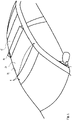
Fig. 2 is an enlarged perspective view of the roof system ofFig. 1 separate from the vehicle. -
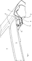
Fig. 3 ,4 and5 are enlarged sectional perspective views along the lines III - III, IV - IV and V - V, respectively, inFig. 2 . -
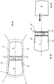
Fig. 6A is a very schematic plan of the fixed roof of the vehicle andFig. 6B is a plan view of a first embodiment of the roof system to be attached to the fixed roof. -
Fig. 7A is a very schematic plan view of the fixed roof of the vehicle together with a second embodiment of the roof system andFig. 7B is a schematic plan view of the roof system ofFig. 7A before it is installed into the vehicle. -
Fig. 8A is a very schematic plan view of the fixed roof of the vehicle together with a third embodiment of the roof system andFig. 8B is a schematic plan view of the roof system ofFig. 8A before it is installed into the vehicle. -
Fig. 9A is a very schematic plan view of the fixed roof of the vehicle together with a fourth embodiment of the roof system andFig. 9B is a schematic plan view of the roof system ofFig. 9A before it is installed into the vehicle. -
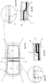
Fig. 10A is a view corresponding to that ofFig. 8A , but also showing the glue beads, with which the panels are glued to the fixed roof of the vehicle. -
Fig. 10B and 10D are enlarged views of details B and D inFig. 10A . -
Fig. 10C and 10E are enlarged cross sections along the line XC - XC inFig. 10B and along line XE - XE inFig. 10D . -
Fig. 11 ,12 and 13 are cross-sections taken at positions similar to those ofFigs. 3 - 5 , but through the embodiments ofFig. 8 or9 . -
Fig. 14 and15 are enlarged sectional perspective views along the lines XIV - XIV and XV - XV, respectively, inFig. 2 . -
Fig. 16 is a cross sectional view corresponding to that ofFig. 11 , but of another embodiment. -
Fig. 17A is a cross-sectional view corresponding to that ofFig. 3 , but of another embodiment. -
Fig. 17B is a part of a view corresponding to that ofFig. 17A but showing another embodiment. -
Fig. 1 shows the upper part of a vehicle, particularly a passenger car. The vehicle may however also be an SUV, a truck, a camper, caravan, or the like. The vehicle has a fixedroof 1, in this case comprising a verylarge opening 2, in which the roof system is arranged. In the embodiment shown inFigs. 1 and2 , the roof system includes an at least semi-transparent first or frontstationary panel 3, a movable,central ventilation panel 4 and a second or rearstationary panel 5. The roof system could, however, also comprise one stationary panel only, either the front or the rear, although thefront panel 3 would be favoured. The panels 3 - 5 are made of glass or of plastic and be made permanently semi-transparent or be provided with a (known) system to vary the transparency of one or more of the panels, for example electronically. - The
central ventilation panel 4 is in this case quite narrow or short in longitudinal (X) direction, but dimensions could be varied. It would also be possible that there are two separate ventilation panels arranged side-by-side in transverse (Y) direction. In the embodiment shown, theventilation panel 4 is movable between a closed position substantially flush withstationary panels ventilation panel 4 is moved upwardly to a rearwardly and upwardly inclined position. Other movements are conceivable as well. -
Fig. 3 ,4 and5 show how the roof system is fixed tolongitudinal reinforcement beams 6 of fixedroof 1 of the vehicle. Theselongitudinal reinforcement beams 6 are also called cantrails. They comprise ahorizontal flange 7 onto which aframe 8 of the roof system can rest.Frame 8 is made primarily from plastic, here Polyurethane (PU) but PBT + ASA, SMA, PP and PAG are also available as frame material. Aglue bead 9 can be used to attachedframe 8 to fixedroof 1. - Especially
Figs. 3 and4 show thatframe 8 comprises areinforcement 10, preferably made of metal, particularly steel. It extends at least along and below the circumference ofventilation panel 4 and includes a plurality of cross bars 11 leaving a plurality ofventilation openings 12. Thereinforcement 10 also extends such that it overlapsflanges 7 ofreinforcement beams 6 of fixedroof 1, so that it can be attached thereto, either directly, for example by (spot) welding, or indirectly by means of glue and/or bolts. As is shown inFig. 4 ,reinforcement 10 may be covered by the plastic offrame 8 at the position offlanges 7. -
Fig. 3 and4 show thatframe 8 may carry aseal 20 below the whole circumference ofmovable panel 4. Downwardly extendingribs 13 may be provided at the transverse sides ofreinforcement 10. Theventilation panel 4 is preferably adjusted by an electric motor through an operating mechanism (not shown), positioned either in the middle or on one or both transverse ends ofpanel 4.Panel 4 may also be split inti two panels arranged side-by-side and each having its own operating mechanism. -
Fig. 5 shows thatplastic frame 8 is also glued byglue bead 9 toflange 7 at the position where no reinforcement is present. Here,plastic frame 8 extends around the whole circumference ofpanels panels frame 8 are first assembled into a unit and during manufacture of the vehicle the unit is built into the vehicle, as illustrated inFig. 6A and 6B . It is also shown there that the vehicle may also be provided with atransverse reinforcement beam 14. This will be further discussed with reference to other embodiments. -
Fig. 7A and 7B shows an embodiment in whichframe 8 is only present aroundmovable panel 4 and is provided with shortlongitudinal protrusions 15 only along their longitudinal sides. This small unit will be built into the vehicle first and only thenpanels frame 8 and on the other sides directly to thelongitudinal reinforcement beams 6 of fixedroof 1 and to transverse beams. -
Fig. 8A and 8B illustrate an embodiment in whichframe 8 is provided with two shortlongitudinal protrusions 15 at the rear only. Longlongitudinal protrusions 16 are arranged at the front offrame 8, such thatfront panel 3 can be glued toframe 8 to form a unit, then built into the vehicle and only thenrear panel 5 is glued toframe 8 and directly to the vehicle. Asframe 8 in this embodiment also does not extend around the whole circumference offront panel 3, this panel will also be partly glued directly to the vehicle. - In the embodiment of
Fig. 9 ,frame 8 haslong protrusions 16 in both rearward and forward direction, so that bothpanels frame 8 before the unit is built into the vehicle. Generally,reinforcement 10 will extend into eithershort protrusions 15 orlong protrusions 16. -
Fig. 10A - 10E again show the embodiment ofFig. 8 as built into the vehicle.Fig. 10C and 10E show the joint whereframe 8 ends andpanels flange 7 of fixedroof 1. InFig. 10C on the right anencapsulation 17 ofpanel 3 is attached to frame 8 by aglue bead 19. This is already done in the factory of the manufacturer of the roof system. It is further shown inFig. 10C thatframe 8 andencapsulation 17 ofpanel 3 are attached toflange 7 byglue bead 9. This is done at the manufacturer of the vehicle. To enable this,encapsulation 17 includes a step 18, so that the lower side offrame 8 and the lower side ofencapsulation 17adjacent frame 8 are substantially flush, and together they are attached toflange 7 byglue bead 9. The same configuration is shown inFig. 10E forrear panel 5. -
Fig. 11 ,12 and 13 are cross sections of the embodiment ofFig. 8 or9 at the positions of those ofFigs. 3 - 5 . It is shown that inFig. 11 thatencapsulation 17 ofpanels seal 21 to sealventilation panel 4 in its closed position. There is awet area 22 belowseals 21 to catch any water seeping through. InFig. 12 ,frame 8 is attached toflange 7, whereas inFig. 13 encapsulation 17 ofpanel 3 is attached to frame 8 byglue bead 19, whileframe 8 is attached toflange 7 of fixedroof 1 byglue bead 9. -
Figs. 14 and15 show howpanels roof 1 at their front at rear sides. Both figures show thatpanels perimeter encapsulation 17 totransverse beams transverse encapsulation encapsulation 17 and attached to ahorizontal flange transverse beam -
Fig. 16 is a cross section through another embodiment in which sunshades 29, 30 are provided, of which a windingroller housing ventilation panel 4. In this way the rollo sunshades can be moved to a closed position below therespective panel semi-transparent panels -
Figs. 17A and 17B show further variations of the roof system havingtransverse reinforcement beam 14 as already shown inFig. 6A . InFig. 17A ,transverse reinforcement beam 14 is part of the roof system and is welded or bolted toreinforcement 10 offrame 8. Thistransverse reinforcement beam 14 will be glued tolongitudinal reinforcement beam 6 of fixedroof 1. InFig. 17B ,transverse reinforcement beam 14 is part of the vehicle and therefore welded or bolted to longitudinal reinforcement beams 6.Frame 8 is glued totransverse beam 14 then. - From the foregoing it will be clear that the invention provides a versatile roof system having low cost and profile, but still allowing ventilation.
- Detailed embodiments of the present invention are disclosed herein; however, it is to be understood that the disclosed embodiments are merely exemplary of the invention, which can be embodied in various forms. Therefore, specific structural and functional details disclosed herein are not to be interpreted as limiting, but merely as a basis for the claims and as a representative basis for teaching one skilled in the art to variously employ the present invention in expectedly any appropriately detailed structure. In particular, features presented and described in separate dependent claims may be applied in combination and any advantageous combination of such claims and embodiments are herewith disclosed.
- Further, the terms and phrases used herein are not intended to be limiting, but rather to provide an understandable description of the invention. The terms "a" or "an", as used herein, are defined as one or more than one. The term plurality, as used herein, is defined as two or more than two. The term another, as used herein, is defined as at least a second or more. The terms including and/or having, as used herein, are defined as comprising (i.e. open language). The term coupled, as used herein, is defined as connected, although not necessarily directly.
- The invention being thus described it is apparent that the same may be varied in many ways. Such variations are not to be regarded as a departure from the spirit and scope of the invention, and all such modifications as would be apparent to one skilled in the art are intended to be included within the scope of the following claims.
Claims (15)
- Roof assembly for attachment to reinforcement beams (6, 14) in a fixed roof (1) of a vehicle, comprising:a frame (8) surrounding at least a part of an opening (2) and configured to be attached to the reinforcement beams of the vehicle, said frame being made primarily of plastic material,a first stationary panel (3) which is at least partly semi-transparent and is at least partly fixed to the frame,at least one movable panel (4), arranged adjacent the stationary panel, anda reinforcement (10) integrated in the frame,characterized in that the reinforcement (10) extends at least around an area covered by the movable panel (4), and along at least a portion of the frame (8) configured to be attached to the reinforcement beams (6, of the vehicle.
- Roof assembly according to claim 1, wherein the at least one movable panel (4) is a ventilation panel which is movable at least between a closed position and a rearwardly and upwardly inclined venting position.
- Roof assembly according to claim 2, wherein the ventilation panel (4) is positioned behind the first stationary panel (3).
- Roof assembly according to claim 3, comprising a second stationary panel (5) positioned behind the ventilation panel (4).
- Roof assembly according to claim 4, wherein the frame (8) is at least partly surrounding the first stationary panel (3) and the ventilation panel (4) and is formed in one piece, the second stationary panel (5) being attachable partly to the frame (8) and partly to the fixed roof of the vehicle.
- Roof assembly according to claim 1, wherein the frame (8) surrounds the ventilation panel (4), and the first stationary panel (3) is attachable partly to the frame and partly to the fixed roof (1) of the vehicle.
- Roof assembly according to claim 1, wherein the reinforcement (10) also extends in longitudinal direction along at least a portion of the first stationary panel (3).
- Roof assembly according to claim 4, wherein the reinforcement (10) also extends in longitudinal direction along at least a portion of the first and second stationary panel (3, 5).
- Roof assembly according to claim 1, wherein the reinforcement (10) is configured to be attached to the reinforcement beams (6) in the vehicle roof extending in longitudinal direction and/or to a transverse reinforcement beam (14) in the vehicle roof extending in transverse direction.
- Roof assembly according to claim 1, wherein the frame (8) includes a transverse reinforcement beam (14) attached to the reinforcement beams (6) of the vehicle roof extending in longitudinal direction.
- Roof assembly according to claim 1, wherein the frame (8) is at least partly made from polyurethane, or from a plastic chosen from the group containing Polybutylene Terephthalate + Acrylonitrile, Styrene Maleic Anhydride, Polypropylene, and glass Reinforced Polyamide.
- Roof assembly according to claim 9 or 10, wherein at least one winding shaft for a windable sunscreen (29, 30) is positioned adjacent to the transverse reinforcement beam (14).
- Vehicle comprising a roof assembly attached to reinforcement beams (6, 14) in a fixed roof (1) of the vehicle, said roof assembly comprising:a frame (8) surrounding at least a part of an opening (2) and attached to at least the reinforcement beams of the vehicle, said frame being made primarily of plastic material,a first stationary panel (3) which is at least partly semi-transparent and is at least partly fixed to the frame,at least one movable panel (4), arranged adjacent to the stationary panel, anda reinforcement (10) integrated in the frame, characterized in that the reinforcement (10) extends at least around an area covered by the movable panel (4), and along at least a portion of the frame (8) that is attached to the reinforcement beams (6, 14) of the vehicle.
- Vehicle according to claim 13, wherein the frame (8) is at least partly surrounding the first stationary panel (3) and the ventilation panel (4) and is formed in one piece, and wherein the second stationary panel (5) is partly attached to the frame (8) and partly to the fixed roof (1) of the vehicle.
- Vehicle according to claim 13, wherein the frame (8) surrounds the ventilation panel (4), and the first stationary panel (3) is partly attached to the frame (8) and partly to the fixed roof (1) of the vehicle, and wherein preferably a second stationary panel (5) is partly attached to the frame (8) and partly attached to the fixed roof (1) of the vehicle.
Applications Claiming Priority (1)
| Application Number | Priority Date | Filing Date | Title |
|---|---|---|---|
| CN202011601311.5A CN114683820A (en) | 2020-12-30 | 2020-12-30 | Roof assembly for a vehicle |
Publications (3)
| Publication Number | Publication Date |
|---|---|
| EP4023536A2 true EP4023536A2 (en) | 2022-07-06 |
| EP4023536A3 EP4023536A3 (en) | 2022-10-05 |
| EP4023536B1 EP4023536B1 (en) | 2025-07-30 |
Family
ID=79020951
Family Applications (1)
| Application Number | Title | Priority Date | Filing Date |
|---|---|---|---|
| EP21216967.6A Active EP4023536B1 (en) | 2020-12-30 | 2021-12-22 | Roof assembly for a vehicle, and vehicle comprising such roof assembly |
Country Status (3)
| Country | Link |
|---|---|
| US (1) | US11890922B2 (en) |
| EP (1) | EP4023536B1 (en) |
| CN (1) | CN114683820A (en) |
Citations (2)
| Publication number | Priority date | Publication date | Assignee | Title |
|---|---|---|---|---|
| DE20103626U1 (en) | 2001-03-01 | 2002-04-11 | Webasto Vehicle Systems International GmbH, 82131 Stockdorf | Ventilation device on a vehicle roof |
| DE102017003968B3 (en) | 2017-04-25 | 2018-05-03 | Audi Ag | Adjustment device for a pivotable roof flap of a vehicle and roof flap with such adjustment |
Family Cites Families (12)
| Publication number | Priority date | Publication date | Assignee | Title |
|---|---|---|---|---|
| US6623068B2 (en) * | 1998-06-18 | 2003-09-23 | Alcan Technology & Management Ag | Roof unit and basic structure of a road-bound vehicle |
| SE516670C2 (en) * | 1998-10-29 | 2002-02-12 | Volvo Ab | Sun-roof |
| US6565149B2 (en) * | 2000-03-10 | 2003-05-20 | Webasto Vehicle Systems International Gmbh | Motor vehicle roof with two covers and a headliner for one such motor vehicle roof |
| DE10019664C2 (en) * | 2000-04-19 | 2003-05-28 | Webasto Vehicle Sys Int Gmbh | Vehicle roof with a transparent roof section and a sun protection device |
| DE102004044670A1 (en) | 2004-09-15 | 2006-03-16 | Arvinmeritor Gmbh | Vehicle body attachment, in particular Fahrzeugdachpaneel |
| DE102005045740B4 (en) * | 2005-09-23 | 2007-12-13 | Magna Car Top Systems Gmbh | Locking between a receiving part and a lid part |
| US7441833B1 (en) * | 2007-05-15 | 2008-10-28 | Webasto Roof Systems, Inc. | Arrangement and method for converting of single panel sunroofs into double panel sunroofs and component parts thereof |
| DE102008061490B3 (en) * | 2008-12-10 | 2010-08-05 | Thyssenkrupp Drauz Nothelfer Gmbh | Body for a motor vehicle and method for producing a motor vehicle body |
| WO2010066213A2 (en) * | 2008-12-12 | 2010-06-17 | Webasto Ag | Roof module with roof opening |
| EP2450239B1 (en) * | 2010-11-04 | 2014-03-19 | Inalfa Roof Systems Group B.V. | Method for connecting two objects and panel using said method |
| WO2018134762A1 (en) * | 2017-01-18 | 2018-07-26 | Sabic Global Technologies B.V. | Composite hybrid roof frame and methods to produce the same |
| EP3868586B1 (en) * | 2020-02-24 | 2023-10-25 | Inalfa Roof Systems Group B.V. | Open roof construction for a vehicle |
-
2020
- 2020-12-30 CN CN202011601311.5A patent/CN114683820A/en active Pending
-
2021
- 2021-12-22 EP EP21216967.6A patent/EP4023536B1/en active Active
- 2021-12-23 US US17/560,853 patent/US11890922B2/en active Active
Patent Citations (2)
| Publication number | Priority date | Publication date | Assignee | Title |
|---|---|---|---|---|
| DE20103626U1 (en) | 2001-03-01 | 2002-04-11 | Webasto Vehicle Systems International GmbH, 82131 Stockdorf | Ventilation device on a vehicle roof |
| DE102017003968B3 (en) | 2017-04-25 | 2018-05-03 | Audi Ag | Adjustment device for a pivotable roof flap of a vehicle and roof flap with such adjustment |
Also Published As
| Publication number | Publication date |
|---|---|
| US20220203812A1 (en) | 2022-06-30 |
| EP4023536B1 (en) | 2025-07-30 |
| CN114683820A (en) | 2022-07-01 |
| EP4023536A3 (en) | 2022-10-05 |
| US11890922B2 (en) | 2024-02-06 |
Similar Documents
| Publication | Publication Date | Title |
|---|---|---|
| EP2154015B1 (en) | Panoramic roof module assemblies for vehicles | |
| KR102607730B1 (en) | Side sill structure of vehicle with opposite sliding door | |
| US9857797B2 (en) | Structure disposed with peripheral information detection sensor, and self-driving vehicle | |
| EP1176042A1 (en) | Vehicle roof with movable panels | |
| US20100038933A1 (en) | Panoramic vehicle roof module assemblies | |
| CN107757504A (en) | For being attached to the sensor outer housing component of motor vehicles | |
| GB2184404A (en) | Motor vehicle with a roof mounted ventilation device | |
| JP4661341B2 (en) | Automotive roof structure | |
| JP2001146141A (en) | Shock absorption structure of front pillar | |
| CN106891707B (en) | Vehicle with skylight and panoramic glass | |
| US20170225719A1 (en) | Structural nodes for a motor vehicle bodywork | |
| EP4023536B1 (en) | Roof assembly for a vehicle, and vehicle comprising such roof assembly | |
| JPH1199961A (en) | Body structure | |
| CN112566806B (en) | Roof modules for passenger car roofs | |
| US10676045B1 (en) | Vehicle assembly | |
| US20250018875A1 (en) | Roof module for forming a vehicle roof and motor vehicle with a roof module | |
| US7549696B1 (en) | Bus side wall construction | |
| US7032963B2 (en) | Motor vehicle roof with a wind deflector element with a spoiler body and process for production thereof | |
| JP2501818B2 (en) | How to assemble a car body | |
| US20060152043A1 (en) | Plastics material elongate member forming part of a roof structure, a roof structure member, a roof arch, a roof frame, and a roof module for a motor vehicle | |
| JP2006327257A (en) | Automotive roof structure | |
| CN107683240A (en) | Structural roofs and vehicles equipped with such roofs | |
| US11110781B2 (en) | Opening structure of tail gate and roof and mounting method thereof | |
| KR100355276B1 (en) | Center pillar double box structure of vehicle | |
| JP2006298021A (en) | Roof reinforcing structure for automobile |
Legal Events
| Date | Code | Title | Description |
|---|---|---|---|
| PUAI | Public reference made under article 153(3) epc to a published international application that has entered the european phase |
Free format text: ORIGINAL CODE: 0009012 |
|
| STAA | Information on the status of an ep patent application or granted ep patent |
Free format text: STATUS: THE APPLICATION HAS BEEN PUBLISHED |
|
| AK | Designated contracting states |
Kind code of ref document: A2 Designated state(s): AL AT BE BG CH CY CZ DE DK EE ES FI FR GB GR HR HU IE IS IT LI LT LU LV MC MK MT NL NO PL PT RO RS SE SI SK SM TR |
|
| PUAL | Search report despatched |
Free format text: ORIGINAL CODE: 0009013 |
|
| AK | Designated contracting states |
Kind code of ref document: A3 Designated state(s): AL AT BE BG CH CY CZ DE DK EE ES FI FR GB GR HR HU IE IS IT LI LT LU LV MC MK MT NL NO PL PT RO RS SE SI SK SM TR |
|
| RIC1 | Information provided on ipc code assigned before grant |
Ipc: B60J 7/16 20060101ALI20220826BHEP Ipc: B60H 1/24 20060101ALI20220826BHEP Ipc: B60J 7/02 20060101ALI20220826BHEP Ipc: B62D 25/06 20060101AFI20220826BHEP |
|
| STAA | Information on the status of an ep patent application or granted ep patent |
Free format text: STATUS: REQUEST FOR EXAMINATION WAS MADE |
|
| 17P | Request for examination filed |
Effective date: 20230404 |
|
| RBV | Designated contracting states (corrected) |
Designated state(s): AL AT BE BG CH CY CZ DE DK EE ES FI FR GB GR HR HU IE IS IT LI LT LU LV MC MK MT NL NO PL PT RO RS SE SI SK SM TR |
|
| GRAP | Despatch of communication of intention to grant a patent |
Free format text: ORIGINAL CODE: EPIDOSNIGR1 |
|
| STAA | Information on the status of an ep patent application or granted ep patent |
Free format text: STATUS: GRANT OF PATENT IS INTENDED |
|
| INTG | Intention to grant announced |
Effective date: 20250310 |
|
| GRAS | Grant fee paid |
Free format text: ORIGINAL CODE: EPIDOSNIGR3 |
|
| GRAA | (expected) grant |
Free format text: ORIGINAL CODE: 0009210 |
|
| STAA | Information on the status of an ep patent application or granted ep patent |
Free format text: STATUS: THE PATENT HAS BEEN GRANTED |
|
| AK | Designated contracting states |
Kind code of ref document: B1 Designated state(s): AL AT BE BG CH CY CZ DE DK EE ES FI FR GB GR HR HU IE IS IT LI LT LU LV MC MK MT NL NO PL PT RO RS SE SI SK SM TR |
|
| REG | Reference to a national code |
Ref country code: GB Ref legal event code: FG4D |
|
| REG | Reference to a national code |
Ref country code: CH Ref legal event code: EP |
|
| REG | Reference to a national code |
Ref country code: DE Ref legal event code: R096 Ref document number: 602021035012 Country of ref document: DE |
|
| REG | Reference to a national code |
Ref country code: IE Ref legal event code: FG4D |
|
| REG | Reference to a national code |
Ref country code: NL Ref legal event code: MP Effective date: 20250730 |
|
| REG | Reference to a national code |
Ref country code: AT Ref legal event code: MK05 Ref document number: 1818665 Country of ref document: AT Kind code of ref document: T Effective date: 20250730 |
|
| PG25 | Lapsed in a contracting state [announced via postgrant information from national office to epo] |
Ref country code: PT Free format text: LAPSE BECAUSE OF FAILURE TO SUBMIT A TRANSLATION OF THE DESCRIPTION OR TO PAY THE FEE WITHIN THE PRESCRIBED TIME-LIMIT Effective date: 20251202 |
|
| PG25 | Lapsed in a contracting state [announced via postgrant information from national office to epo] |
Ref country code: IS Free format text: LAPSE BECAUSE OF FAILURE TO SUBMIT A TRANSLATION OF THE DESCRIPTION OR TO PAY THE FEE WITHIN THE PRESCRIBED TIME-LIMIT Effective date: 20251130 |
|
| PG25 | Lapsed in a contracting state [announced via postgrant information from national office to epo] |
Ref country code: NO Free format text: LAPSE BECAUSE OF FAILURE TO SUBMIT A TRANSLATION OF THE DESCRIPTION OR TO PAY THE FEE WITHIN THE PRESCRIBED TIME-LIMIT Effective date: 20251030 |
|
| REG | Reference to a national code |
Ref country code: LT Ref legal event code: MG9D |
|
| PG25 | Lapsed in a contracting state [announced via postgrant information from national office to epo] |
Ref country code: AT Free format text: LAPSE BECAUSE OF FAILURE TO SUBMIT A TRANSLATION OF THE DESCRIPTION OR TO PAY THE FEE WITHIN THE PRESCRIBED TIME-LIMIT Effective date: 20250730 |
|
| PG25 | Lapsed in a contracting state [announced via postgrant information from national office to epo] |
Ref country code: FI Free format text: LAPSE BECAUSE OF FAILURE TO SUBMIT A TRANSLATION OF THE DESCRIPTION OR TO PAY THE FEE WITHIN THE PRESCRIBED TIME-LIMIT Effective date: 20250730 |
|
| PG25 | Lapsed in a contracting state [announced via postgrant information from national office to epo] |
Ref country code: HR Free format text: LAPSE BECAUSE OF FAILURE TO SUBMIT A TRANSLATION OF THE DESCRIPTION OR TO PAY THE FEE WITHIN THE PRESCRIBED TIME-LIMIT Effective date: 20250730 Ref country code: NL Free format text: LAPSE BECAUSE OF FAILURE TO SUBMIT A TRANSLATION OF THE DESCRIPTION OR TO PAY THE FEE WITHIN THE PRESCRIBED TIME-LIMIT Effective date: 20250730 |
|
| PGFP | Annual fee paid to national office [announced via postgrant information from national office to epo] |
Ref country code: FR Payment date: 20251230 Year of fee payment: 5 |
|
| PG25 | Lapsed in a contracting state [announced via postgrant information from national office to epo] |
Ref country code: GR Free format text: LAPSE BECAUSE OF FAILURE TO SUBMIT A TRANSLATION OF THE DESCRIPTION OR TO PAY THE FEE WITHIN THE PRESCRIBED TIME-LIMIT Effective date: 20251031 |
|
| PG25 | Lapsed in a contracting state [announced via postgrant information from national office to epo] |
Ref country code: SE Free format text: LAPSE BECAUSE OF FAILURE TO SUBMIT A TRANSLATION OF THE DESCRIPTION OR TO PAY THE FEE WITHIN THE PRESCRIBED TIME-LIMIT Effective date: 20250730 |
|
| PG25 | Lapsed in a contracting state [announced via postgrant information from national office to epo] |
Ref country code: LV Free format text: LAPSE BECAUSE OF FAILURE TO SUBMIT A TRANSLATION OF THE DESCRIPTION OR TO PAY THE FEE WITHIN THE PRESCRIBED TIME-LIMIT Effective date: 20250730 |
|
| PG25 | Lapsed in a contracting state [announced via postgrant information from national office to epo] |
Ref country code: BG Free format text: LAPSE BECAUSE OF FAILURE TO SUBMIT A TRANSLATION OF THE DESCRIPTION OR TO PAY THE FEE WITHIN THE PRESCRIBED TIME-LIMIT Effective date: 20250730 Ref country code: PL Free format text: LAPSE BECAUSE OF FAILURE TO SUBMIT A TRANSLATION OF THE DESCRIPTION OR TO PAY THE FEE WITHIN THE PRESCRIBED TIME-LIMIT Effective date: 20250730 |
|
| PG25 | Lapsed in a contracting state [announced via postgrant information from national office to epo] |
Ref country code: RS Free format text: LAPSE BECAUSE OF FAILURE TO SUBMIT A TRANSLATION OF THE DESCRIPTION OR TO PAY THE FEE WITHIN THE PRESCRIBED TIME-LIMIT Effective date: 20251030 |
|
| PG25 | Lapsed in a contracting state [announced via postgrant information from national office to epo] |
Ref country code: ES Free format text: LAPSE BECAUSE OF FAILURE TO SUBMIT A TRANSLATION OF THE DESCRIPTION OR TO PAY THE FEE WITHIN THE PRESCRIBED TIME-LIMIT Effective date: 20250730 |
|
| PG25 | Lapsed in a contracting state [announced via postgrant information from national office to epo] |
Ref country code: RO Free format text: LAPSE BECAUSE OF FAILURE TO SUBMIT A TRANSLATION OF THE DESCRIPTION OR TO PAY THE FEE WITHIN THE PRESCRIBED TIME-LIMIT Effective date: 20250730 |
|
| PG25 | Lapsed in a contracting state [announced via postgrant information from national office to epo] |
Ref country code: SM Free format text: LAPSE BECAUSE OF FAILURE TO SUBMIT A TRANSLATION OF THE DESCRIPTION OR TO PAY THE FEE WITHIN THE PRESCRIBED TIME-LIMIT Effective date: 20250730 |
|
| PG25 | Lapsed in a contracting state [announced via postgrant information from national office to epo] |
Ref country code: DK Free format text: LAPSE BECAUSE OF FAILURE TO SUBMIT A TRANSLATION OF THE DESCRIPTION OR TO PAY THE FEE WITHIN THE PRESCRIBED TIME-LIMIT Effective date: 20250730 |
|
| PGFP | Annual fee paid to national office [announced via postgrant information from national office to epo] |
Ref country code: DE Payment date: 20251229 Year of fee payment: 5 |
|
| PG25 | Lapsed in a contracting state [announced via postgrant information from national office to epo] |
Ref country code: IT Free format text: LAPSE BECAUSE OF FAILURE TO SUBMIT A TRANSLATION OF THE DESCRIPTION OR TO PAY THE FEE WITHIN THE PRESCRIBED TIME-LIMIT Effective date: 20250730 |