EP4023402B1 - Rastvorrichtung - Google Patents
Rastvorrichtung Download PDFInfo
- Publication number
- EP4023402B1 EP4023402B1 EP20895211.9A EP20895211A EP4023402B1 EP 4023402 B1 EP4023402 B1 EP 4023402B1 EP 20895211 A EP20895211 A EP 20895211A EP 4023402 B1 EP4023402 B1 EP 4023402B1
- Authority
- EP
- European Patent Office
- Prior art keywords
- block
- punch
- mounting groove
- notching apparatus
- holder
- Prior art date
- Legal status (The legal status is an assumption and is not a legal conclusion. Google has not performed a legal analysis and makes no representation as to the accuracy of the status listed.)
- Active
Links
Images


Classifications
-
- B—PERFORMING OPERATIONS; TRANSPORTING
- B26—HAND CUTTING TOOLS; CUTTING; SEVERING
- B26F—PERFORATING; PUNCHING; CUTTING-OUT; STAMPING-OUT; SEVERING BY MEANS OTHER THAN CUTTING
- B26F1/00—Perforating; Punching; Cutting-out; Stamping-out; Apparatus therefor
- B26F1/02—Perforating by punching, e.g. with relatively-reciprocating punch and bed
- B26F1/12—Perforating by punching, e.g. with relatively-reciprocating punch and bed to notch margins of work
-
- B—PERFORMING OPERATIONS; TRANSPORTING
- B21—MECHANICAL METAL-WORKING WITHOUT ESSENTIALLY REMOVING MATERIAL; PUNCHING METAL
- B21D—WORKING OR PROCESSING OF SHEET METAL OR METAL TUBES, RODS OR PROFILES WITHOUT ESSENTIALLY REMOVING MATERIAL; PUNCHING METAL
- B21D28/00—Shaping by press-cutting; Perforating
- B21D28/02—Punching blanks or articles with or without obtaining scrap; Notching
- B21D28/14—Dies
-
- B—PERFORMING OPERATIONS; TRANSPORTING
- B21—MECHANICAL METAL-WORKING WITHOUT ESSENTIALLY REMOVING MATERIAL; PUNCHING METAL
- B21D—WORKING OR PROCESSING OF SHEET METAL OR METAL TUBES, RODS OR PROFILES WITHOUT ESSENTIALLY REMOVING MATERIAL; PUNCHING METAL
- B21D28/00—Shaping by press-cutting; Perforating
- B21D28/24—Perforating, i.e. punching holes
- B21D28/26—Perforating, i.e. punching holes in sheets or flat parts
-
- B—PERFORMING OPERATIONS; TRANSPORTING
- B26—HAND CUTTING TOOLS; CUTTING; SEVERING
- B26F—PERFORATING; PUNCHING; CUTTING-OUT; STAMPING-OUT; SEVERING BY MEANS OTHER THAN CUTTING
- B26F1/00—Perforating; Punching; Cutting-out; Stamping-out; Apparatus therefor
- B26F1/02—Perforating by punching, e.g. with relatively-reciprocating punch and bed
- B26F1/14—Punching tools; Punching dies
-
- H—ELECTRICITY
- H01—ELECTRIC ELEMENTS
- H01M—PROCESSES OR MEANS, e.g. BATTERIES, FOR THE DIRECT CONVERSION OF CHEMICAL ENERGY INTO ELECTRICAL ENERGY
- H01M10/00—Secondary cells; Manufacture thereof
- H01M10/04—Construction or manufacture in general
- H01M10/0404—Machines for assembling batteries
-
- H—ELECTRICITY
- H01—ELECTRIC ELEMENTS
- H01M—PROCESSES OR MEANS, e.g. BATTERIES, FOR THE DIRECT CONVERSION OF CHEMICAL ENERGY INTO ELECTRICAL ENERGY
- H01M10/00—Secondary cells; Manufacture thereof
- H01M10/05—Accumulators with non-aqueous electrolyte
- H01M10/058—Construction or manufacture
- H01M10/0585—Construction or manufacture of accumulators having only flat construction elements, i.e. flat positive electrodes, flat negative electrodes and flat separators
-
- H—ELECTRICITY
- H01—ELECTRIC ELEMENTS
- H01M—PROCESSES OR MEANS, e.g. BATTERIES, FOR THE DIRECT CONVERSION OF CHEMICAL ENERGY INTO ELECTRICAL ENERGY
- H01M4/00—Electrodes
- H01M4/02—Electrodes composed of, or comprising, active material
- H01M4/04—Processes of manufacture in general
-
- H—ELECTRICITY
- H01—ELECTRIC ELEMENTS
- H01M—PROCESSES OR MEANS, e.g. BATTERIES, FOR THE DIRECT CONVERSION OF CHEMICAL ENERGY INTO ELECTRICAL ENERGY
- H01M4/00—Electrodes
- H01M4/02—Electrodes composed of, or comprising, active material
- H01M4/13—Electrodes for accumulators with non-aqueous electrolyte, e.g. for lithium-accumulators; Processes of manufacture thereof
-
- H—ELECTRICITY
- H01—ELECTRIC ELEMENTS
- H01M—PROCESSES OR MEANS, e.g. BATTERIES, FOR THE DIRECT CONVERSION OF CHEMICAL ENERGY INTO ELECTRICAL ENERGY
- H01M50/00—Constructional details or processes of manufacture of the non-active parts of electrochemical cells other than fuel cells, e.g. hybrid cells
- H01M50/50—Current conducting connections for cells or batteries
- H01M50/531—Electrode connections inside a battery casing
-
- B—PERFORMING OPERATIONS; TRANSPORTING
- B21—MECHANICAL METAL-WORKING WITHOUT ESSENTIALLY REMOVING MATERIAL; PUNCHING METAL
- B21D—WORKING OR PROCESSING OF SHEET METAL OR METAL TUBES, RODS OR PROFILES WITHOUT ESSENTIALLY REMOVING MATERIAL; PUNCHING METAL
- B21D28/00—Shaping by press-cutting; Perforating
- B21D28/02—Punching blanks or articles with or without obtaining scrap; Notching
- B21D28/22—Notching the peripheries of circular blanks, e.g. laminations for dynamo-electric machines
-
- B—PERFORMING OPERATIONS; TRANSPORTING
- B26—HAND CUTTING TOOLS; CUTTING; SEVERING
- B26F—PERFORATING; PUNCHING; CUTTING-OUT; STAMPING-OUT; SEVERING BY MEANS OTHER THAN CUTTING
- B26F2210/00—Perforating, punching, cutting-out, stamping-out, severing by means other than cutting of specific products
- B26F2210/02—Perforating, punching, cutting-out, stamping-out, severing by means other than cutting of specific products of stacked sheets
-
- Y—GENERAL TAGGING OF NEW TECHNOLOGICAL DEVELOPMENTS; GENERAL TAGGING OF CROSS-SECTIONAL TECHNOLOGIES SPANNING OVER SEVERAL SECTIONS OF THE IPC; TECHNICAL SUBJECTS COVERED BY FORMER USPC CROSS-REFERENCE ART COLLECTIONS [XRACs] AND DIGESTS
- Y02—TECHNOLOGIES OR APPLICATIONS FOR MITIGATION OR ADAPTATION AGAINST CLIMATE CHANGE
- Y02E—REDUCTION OF GREENHOUSE GAS [GHG] EMISSIONS, RELATED TO ENERGY GENERATION, TRANSMISSION OR DISTRIBUTION
- Y02E60/00—Enabling technologies; Technologies with a potential or indirect contribution to GHG emissions mitigation
- Y02E60/10—Energy storage using batteries
Definitions
- the present invention relates to a notching apparatus with which an electrode substrate is cut and processed into an individual electrode in which an electrode tab is formed and, more specifically, to a notching apparatus in which a punch mounted and fixed to a holder is prevented from being shaken.
- Lithium secondary batteries which are chargeable/dischargeable and lightweight and have high output densities are being widely used as energy sources for various devices.
- the lithium secondary batteries have attracted considerable attention as power sources for hybrid electric vehicles (HEV), plug-in hybrid electric vehicles (PHEV), battery electric vehicles (BEV), and electric vehicles (EV), which have been developed to solve limitations, for example, air pollution and green-house gases, caused by existing internal-combustion engine vehicles that use fossil fuels such as gasoline and diesel vehicles.
- HEV hybrid electric vehicles
- PHEV plug-in hybrid electric vehicles
- BEV battery electric vehicles
- EV electric vehicles
- Such a secondary battery generally has a structure comprising: an electrode assembly in which electrodes (a positive electrode, a negative electrode) and a separator are alternately stacked; an electrolyte for moving ions to the electrodes; and a case in which the electrode assembly and the electrolyte are accommodated.
- a method for manufacturing the secondary battery may be mainly divided into: an electrode plate process of manufacturing each of a positive electrode and a negative electrode; an assembly process of manufacturing an electrode assembly using the positive electrode and the negative electrode and inserting the electrode assembly into the case together with an electrolyte; and a formation process of activating ion movement of the electrode assembly.
- an electrode plate process of manufacturing each of a positive electrode and a negative electrode an assembly process of manufacturing an electrode assembly using the positive electrode and the negative electrode and inserting the electrode assembly into the case together with an electrolyte
- a formation process of activating ion movement of the electrode assembly is divided into individual sub-processes.
- the electrode plate process comprises: a mixing process of adding a conductive material and a binder to an active material and mixing the same; a coating process of applying a mixed active material onto a collector; a press process of pressing the active material to a surface of the collector; and a notching and slitting process (a notching process) of cutting an electrode substrate, which is manufactured by adhering the active material to the surface of the collector, into a desired size and then (or simultaneously with the cutting) shearing the cut electrode substrate so as to form an electrode tab.
- the electrode substrate in which the active material is applied on the surface of the collector is in a cut state to a certain size, and on the electrode substrate, formed are a coating portion coated with the active material and a non-coating portion not coated with the active material.
- the active material in the electrode substrate is applied with a smaller width than the collector, and thus the electrode substrate has a structure in which non-coating portions are formed on both side edges with a coating portion therebetween.
- a notching apparatus for cutting the electrode substrate to form an electrode tab is generally configured with a punching (press) die that facilitates uniform repeatable processes.
- the punching die used in the notching apparatus comprises an upper die and a lower die (or has one of an upper die and a lower die and comprises a supporter instead of the other).
- One of the upper die and the lower die is fixed, and the other is configured to be vertically slidable to periodically descend and punch an electrode substrate, which is a punch target, while the electrode substrate moves between the upper die and the lower die.
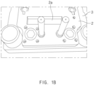
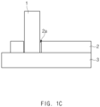
- the sliding upper die or lower die has a structure in which a plate-shaped holder 2 is coupled to a plate-shape base 3.
- a mounting groove 2a is provided in the holder 2, and a punch 1, which strikes the electrode substrate to form a shape or cuts the electrode substrate, is coupled to the mounting groove 2a.
- FIG. 1A illustrating a state in which the punch 1 is coupled to the mounting groove 2a of the holder 2
- FIG. 1B illustrating a state in which the punch 1 is removed from FIG. 1A
- FIG. 1C illustrating a cross-section of portions of FIG. 1A in which the punch 1 is mounted
- the punch 1 is in a state of being inserted into the mounting groove 2a, and the mounting groove 2a is provided to have the same size in a direction in which the punch 1 is inserted.
- US 2001/020410 A1 discloses a notching apparatus. A block with an inclined surface and a complementary inclined wedge are used to clamp the punch.
- a main objective of the present invention is to provide a notching apparatus in which a gap to be generated in a mounting groove is minimized to prevent a punch from shaking.
- the present invention which is defined in claim 1, provides a notching apparatus in which a punch descends to notch an electrode as defined in the appended set of claims, the notching apparatus comprising: a holder having one surface in which a mounting groove is provided; the punch having one end inserted into the mounting groove; and a block inserted into the mounting groove together with the punch, wherein, when inserted into the mounting groove, the block presses the punch so that the punch comes into close contact with one of inner surfaces of the mounting groove.
- the mounting groove comprises a first inner surface perpendicular to a bottom surface of the holder and a second inner surface inclined with respect to the bottom surface of the holder, and the block enters in contact with the second inner surface to press the punch toward the first inner surface.
- a portion of the block, which is in contact with the second inner surface, is provided as an inclined surface, and when the portion provided as the inclined surface comes into contact with the second inner surface, an opposite surface of the inclined surface of the block is parallel to an outer circumferential surface of the punch to come into contact with the punch.
- an angle at a point where a virtual line extending from the inclined surface meets a virtual line extending from the opposite surface ranges from 0.5° to 2°.
- Friction force between the block and the second inner surface is greater than that between the block and the first inner surface.
- the block may be made of a metal material having a friction coefficient greater than that of the punch.
- the block is punched to provide a coupling hole, and a female screw thread is provided on an inner circumferential surface of the coupling hole.
- friction force between the second inner surface and the block is greater than that between the block and the punch. That is, a surface between the second inner surface and the block is rougher than that between the block and the punch to increase in friction force. Also, it is desirable the block is made of the same metal material as the holder.
- the present invention may further provide an electrode which is notched by the notching apparatus having the above-described configuration and an electrode assembly which is manufactured by stacking the plurality of electrodes.
- the present invention having the above-described configuration may prevent the punch from shaking because the wedge-shaped block is inserted into the mounting groove together with the punch and presses the punch so that the punch comes into close contact with one of the inner surfaces of the mounting groove.
- the block Since the friction force between the block and the second inner surface is greater than the friction force between the block and the first inner surface, the block may be prevented from separating.
- the block is punched to provide the coupling hole, and the female screw thread is provided on the inner circumferential surface of the coupling hole.
- the block may be removed using a common tool and a dedicated tool.
- the present invention is to achieve the above-described object and relates to a notching apparatus in which a punch descends to notch an electrode.
- a punch descends to notch an electrode.
- a notching apparatus in the embodiment is provided as a punching die that comprises an upper die and a lower die (or at least one of the upper die and the lower die) as described above. That is, one of the upper die and the lower die is fixed, and the other is configured to be vertically slidable to periodically descend and punch an electrode substrate, which is a punch target, while the electrode substrate moves between the upper die and the lower die.
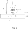
- a punch 10 and a holder 20 are mounted on one of the upper die and the lower die, which ascends and descends to perform punching.
- the sliding die has a structure in which a plate-shaped holder 20 is coupled to a plate-shaped base 30.
- the mounting groove 23 is provided in the holder 20, and the punch 10, which strikes the electrode substrate to form a shape or cuts the electrode substrate, and the block 40 are inserted into the mounting groove 23.
- the block 40 has a wedge structure, which is tapered toward one side in a longitudinal direction so as to press the punch 10, so that the punch 10 comes into close contact with one of inner surfaces of the mounting groove 23 when the block 40 is inserted into the mounting groove 23.
- one surface thereof is formed as an inclined surface 41, and the reverse side (an opposite surface) is formed as a vertical surface 42.
- an included angle ⁇ is formed at a point where a virtual line extending from the inclined surface 41 meets a virtual line extending from the opposite surface.
- the included angle ⁇ ranges from 0.5° to 2°.
- the included angle ⁇ is exaggeratedly illustrated in FIGS. 2 and 3 so as to clearly show a state in which the inclined surface 41 is formed, it is desirable that the actual included angle ⁇ ranges from 0.5° to 2°, and it is desirable that the included angle ⁇ does not exceed 20° as much as possible.
- the mounting groove 23 comprises a first inner surface 21 perpendicular to a bottom surface and/or a top surface of the holder 20 and a second inner surface 22 inclined with respect to the bottom surface and/or the top surface of the holder 20.
- the punch 10 is pressed to be brought into close contact with the first inner surface 21. That is, when the inclined surface 41 of the block 40 is inserted while sliding on the second inner surface 22, the block 40 presses the punch 10 in the left direction in FIG. 2 , and the punch 10 is pressed and brought into contact with the first inner surface 21.
- the top surface to be exposed when the block 40 is inserted is punched to a certain depth to provide a coupling hole 43, and a female screw thread is provided on an inner circumferential surface of the coupling hole 43.
- the female screw thread may be engaged with and fixed to a male screw thread of a dedicated tool for removing the block 40.
- a notching apparatus in the embodiment provides a structure which has the same structure as the notching apparatus provided in the first embodiment and is capable of efficiently preventing the block 40 from being separating.
- an inclined surface 41 of the block 40 and the second inner surface 22 of the mounting groove 23 in the embodiment have relatively more uneven surfaces (have high surface roughness), and friction force may further increase.
- friction force may increase by imparting rough surfaces to areas in which a vertical surface 42 of the block 40 and the punch are in contact with each other.
- surfaces in which the vertical surface 42 of the block 40 and the punch 10 are in contact with each other are relatively smoother (have low surface roughness).
- FIG. 3 illustrates that the areas in which the vertical surface 42 of the block 40 and the punch 10 are in contact with each other have the smooth surfaces while the areas between the inclined surface 41 of the block 40 and the second inner surface 22 of the mounting groove 23 have the uneven surfaces.
- the areas between the inclined surface 41 of the block 40 and the second inner surface 22 of the mounting groove 23 may have the smooth surfaces, and the areas in which the vertical surface 42 of the block 40 and the punch 10 are in contact with each other may have the uneven surfaces.
- the areas between the inclined surface 41 of the block 40 and the second inner surface 22 of the mounting groove 23 and the surfaces in which the vertical surface 42 of the block 40 and the punch 10 are in contact with each other may have appropriate roughness.
- the block 40 is made of the same metal material as the holder 20 so as to minimize deformation of the block 40 due to external impact and heat as much as possible.
- different roughness are given to the surfaces to increase the friction force, and thus separation may be prevented.
- the block 40 may be made of a metal material having a friction coefficient greater than that of the punch 10.
- the present invention having the above-described configuration may prevent the punch 10 from shaking because the wedge-shaped block 40 is inserted into the mounting groove 23 together with the punch 10 and presses the punch 10 so that the punch 10 comes into close contact with one of the inner surfaces of the mounting groove 23.
- the block 40 Since the friction force between the block 40 and the second inner surface 22 is greater than the friction force between the block 40 and the first inner surface 21, the block 40 may be prevented from separating.
- the block 40 is punched to provide a coupling hole 43, and a female screw thread is provided on an inner circumferential surface of the coupling hole 43.
- the block 40 may be removed using a common tool and a dedicated tool.
Landscapes
- Engineering & Computer Science (AREA)
- Mechanical Engineering (AREA)
- Chemical & Material Sciences (AREA)
- Chemical Kinetics & Catalysis (AREA)
- Electrochemistry (AREA)
- General Chemical & Material Sciences (AREA)
- Life Sciences & Earth Sciences (AREA)
- Forests & Forestry (AREA)
- Manufacturing & Machinery (AREA)
- Materials Engineering (AREA)
- Battery Electrode And Active Subsutance (AREA)
- Mounting, Exchange, And Manufacturing Of Dies (AREA)
- Punching Or Piercing (AREA)
- Perforating, Stamping-Out Or Severing By Means Other Than Cutting (AREA)
Claims (7)
- Einkerbvorrichtung, bei welcher ein Stempel zum Einkerben einer Elektrode niedergeht, wobei die Einkerbvorrichtung umfasst:eine Halterung (20), welche eine Fläche aufweist, in welcher eine Befestigungsnut (23) bereitgestellt ist;den Stempel (10), welcher ein in die Befestigungsnut (23) eingeführtes Ende aufweist, undeinen Block (40), welcher zusammen mit dem Stempel (10) in die Befestigungsnut (23) eingeführt ist,wobei der Block (40), wenn er in die Befestigungsnut (23) eingeführt ist, den Stempel (10) derart drückt, dass der Stempel (10) mit einer der inneren Flächen der Befestigungsnut (23) in engen Kontakt kommt,wobei die Befestigungsnut (23) eine erste innere Fläche (21), welche senkrecht zu einer Bodenfläche der Halterung (20) ist, und eine zweite innere Fläche (22) umfasst, welche in Bezug auf die Bodenfläche der Halterung (20) geneigt ist; undder Block (40) in Kontakt mit der zweiten inneren Fläche (22) tritt, um den Stempel (10) in Richtung der ersten inneren Fläche (21) zu drücken,wobei ein Abschnitt des Blocks (40), welcher in Kontakt mit der zweiten inneren Fläche (22) ist, als eine geneigte Fläche bereitgestellt ist; undwenn der als die geneigte Fläche bereitgestellte Abschnitt in Kontakt mit der zweiten inneren Fläche (22) kommt, eine entgegengesetzte Fläche der geneigten Fläche des Blocks (40) parallel zu einer äußeren Umfangsfläche des Stempels (10) ist, um mit dem Stempel (10) in Kontakt zu kommen,wobei eine Reibungskraft zwischen der zweiten inneren Fläche (22) und dem Block (40) größer ist als die zwischen dem Block (40) und dem Stempel (10).
- Einkerbvorrichtung nach Anspruch 1, wobei in dem Block (40) ein Winkel an einer Stelle, an welcher eine sich von der geneigten Fläche erstreckende virtuelle Linie auf eine sich von der entgegengesetzten Fläche erstreckende virtuelle Linie trifft, von 0,5° bis 2° reicht.
- Einkerbvorrichtung nach Anspruch 1, wobei eine Reibungskraft zwischen dem Block (40) und der zweiten inneren Fläche (22) größer ist als die zwischen dem Block (40) und der ersten inneren Fläche (21).
- Einkerbvorrichtung nach Anspruch 1, wobei der Block (40) gelocht ist, um ein Kopplungsloch (43) bereitzustellen, und
ein Innengewinde an einer inneren Umfangsfläche des Kopplungslochs (43) bereitgestellt ist. - Einkerbvorrichtung nach Anspruch 1, wobei der Block (40) aus einem Metallmaterial hergestellt ist, welches einen Reibungskoeffizienten aufweist, welcher größer als der des Stempels (10) ist.
- Einkerbvorrichtung nach Anspruch 1, wobei eine Fläche zwischen der zweiten inneren Fläche (22) und dem Block (40) zur Erhöhung der Reibungskraft rauer ist als die zwischen dem Block (40) und dem Stempel (10).
- Einkerbvorrichtung nach Anspruch 1, wobei der Block (40) aus dem gleichen Metallmaterial wie die Halterung (10) hergestellt ist.
Applications Claiming Priority (2)
| Application Number | Priority Date | Filing Date | Title |
|---|---|---|---|
| KR1020190160231A KR102735715B1 (ko) | 2019-12-04 | 2019-12-04 | 노칭장치 |
| PCT/KR2020/006118 WO2021112347A1 (ko) | 2019-12-04 | 2020-05-08 | 노칭장치 |
Publications (3)
| Publication Number | Publication Date |
|---|---|
| EP4023402A1 EP4023402A1 (de) | 2022-07-06 |
| EP4023402A4 EP4023402A4 (de) | 2022-11-16 |
| EP4023402B1 true EP4023402B1 (de) | 2024-08-14 |
Family
ID=76222023
Family Applications (1)
| Application Number | Title | Priority Date | Filing Date |
|---|---|---|---|
| EP20895211.9A Active EP4023402B1 (de) | 2019-12-04 | 2020-05-08 | Rastvorrichtung |
Country Status (7)
| Country | Link |
|---|---|
| US (1) | US20240033803A1 (de) |
| EP (1) | EP4023402B1 (de) |
| KR (1) | KR102735715B1 (de) |
| CN (1) | CN114502343A (de) |
| ES (1) | ES2987019T3 (de) |
| HU (1) | HUE068471T2 (de) |
| WO (1) | WO2021112347A1 (de) |
Families Citing this family (4)
| Publication number | Priority date | Publication date | Assignee | Title |
|---|---|---|---|---|
| KR102840162B1 (ko) * | 2022-01-12 | 2025-07-29 | 이인규 | 각도 조절이 가능한 전지 극판소재 가공 절단장치 |
| KR102455256B1 (ko) | 2022-04-06 | 2022-10-18 | 주식회사 티더블유하이텍 | 전극 제조용 전단금형 |
| KR102455261B1 (ko) | 2022-04-06 | 2022-10-18 | 주식회사 티더블유하이텍 | 전극 제조용 전단금형 |
| KR102475580B1 (ko) | 2022-05-02 | 2022-12-08 | 주식회사 유진테크놀로지 | 이차전지의 전극 가공용 노칭금형 |
Family Cites Families (20)
| Publication number | Priority date | Publication date | Assignee | Title |
|---|---|---|---|---|
| JPS57134219A (en) * | 1981-02-13 | 1982-08-19 | Nissan Motor Co Ltd | Material holding device for press die for bulging |
| US4611519A (en) * | 1984-09-13 | 1986-09-16 | Hagerty Lloyd A | Radius corner forming apparatus and method |
| US4993291A (en) * | 1988-06-13 | 1991-02-19 | Keymak Company | Key cutting apparatus |
| FR2636256B1 (fr) * | 1988-09-13 | 1994-07-08 | Pignon Guy | Dispositif pour fixer des elements d'outils de presse dans leur support |
| FR2661341B2 (fr) * | 1988-09-13 | 1994-09-09 | Pignon Guy | Dispositif pour fixer des elements d'outils de presse dans leur support. |
| US6311597B1 (en) * | 1999-05-24 | 2001-11-06 | Humdinger, Inc. | Self-guiding punch and die set |
| US6182545B1 (en) * | 1999-07-12 | 2001-02-06 | Francis Richard Janek, Jr. | Wedge-lockable removable punch and die bushing in retainer |
| US6669399B2 (en) * | 1999-07-12 | 2003-12-30 | Wedgelock Systems, Ltd. | Wedge-lockable removable punch and die bushing in retainer |
| US7000523B2 (en) * | 2001-08-09 | 2006-02-21 | Carl Manufacturing Co., Ltd. | Blade holder and support member for perforator |
| US6877353B2 (en) * | 2003-05-13 | 2005-04-12 | Kegar Technologies, Llc | Die button extractor |
| US7779665B2 (en) * | 2006-10-30 | 2010-08-24 | Wilson Tool International Inc. | Press brake die holder technology |
| JP5346733B2 (ja) * | 2009-08-03 | 2013-11-20 | 大同工業株式会社 | 孔明け装置 |
| KR101115299B1 (ko) * | 2011-06-13 | 2012-03-13 | (주)엘케이이노베이션 | 2차전지용 극판 커팅장치 |
| JP2013102044A (ja) * | 2011-11-08 | 2013-05-23 | Renesas Electronics Corp | 半導体装置の製造方法、及び、リード切断装置 |
| KR200471246Y1 (ko) * | 2012-03-07 | 2014-02-12 | 정풍건 | 공작물 클램핑용 바이스 |
| CN105107940A (zh) * | 2015-09-17 | 2015-12-02 | 无锡明豪汽车轻量化技术应用有限公司 | 模具迫紧式冲头固定座 |
| KR101857096B1 (ko) * | 2016-08-01 | 2018-05-11 | 안혁 | 전지 극판 가공 절단장치 |
| KR101813249B1 (ko) * | 2017-02-10 | 2017-12-29 | 신현집 | 리튬 2차 전지의 젤리롤 탭 절단장치 |
| KR102354280B1 (ko) * | 2018-02-08 | 2022-01-21 | 주식회사 엘지에너지솔루션 | 이차전지용 노칭장치 및 방법 |
| JP7488491B2 (ja) * | 2020-02-25 | 2024-05-22 | 日本製鉄株式会社 | クランクシャフト及びその製造方法 |
-
2019
- 2019-12-04 KR KR1020190160231A patent/KR102735715B1/ko active Active
-
2020
- 2020-05-08 ES ES20895211T patent/ES2987019T3/es active Active
- 2020-05-08 US US17/768,792 patent/US20240033803A1/en active Pending
- 2020-05-08 WO PCT/KR2020/006118 patent/WO2021112347A1/ko not_active Ceased
- 2020-05-08 EP EP20895211.9A patent/EP4023402B1/de active Active
- 2020-05-08 CN CN202080068136.XA patent/CN114502343A/zh active Pending
- 2020-05-08 HU HUE20895211A patent/HUE068471T2/hu unknown
Also Published As
| Publication number | Publication date |
|---|---|
| CN114502343A (zh) | 2022-05-13 |
| EP4023402A4 (de) | 2022-11-16 |
| ES2987019T3 (es) | 2024-11-13 |
| HUE068471T2 (hu) | 2024-12-28 |
| KR102735715B1 (ko) | 2024-11-29 |
| KR20210070134A (ko) | 2021-06-14 |
| WO2021112347A1 (ko) | 2021-06-10 |
| US20240033803A1 (en) | 2024-02-01 |
| EP4023402A1 (de) | 2022-07-06 |
Similar Documents
| Publication | Publication Date | Title |
|---|---|---|
| EP4023402B1 (de) | Rastvorrichtung | |
| KR102475580B1 (ko) | 이차전지의 전극 가공용 노칭금형 | |
| KR101759570B1 (ko) | 전극 시트를 고정하는 구조의 롤러를 포함하는 노칭 장치 | |
| EP2555304A1 (de) | Batteriezelle | |
| KR20220035741A (ko) | 초음파 절삭기를 포함하는 전극조립체 제조장치 및 이를 이용한 전극조립체 제조방법 | |
| US20130014625A1 (en) | Electrode plate manufacturing device | |
| EP2874225A1 (de) | Verfahren zur befestigung einer elektrodenanordnung mittels eines bandes | |
| EP3032609B1 (de) | Kerbungsvorrichtung mit überschussentfernungsteil | |
| KR101826142B1 (ko) | 전극 조립체 및 그 제조 방법과 이차 전지 | |
| KR102023735B1 (ko) | 일체형의 다이 및 스트리퍼를 포함하는 노칭 장치 | |
| US9502712B2 (en) | Method of manufacturing battery electrode | |
| JP4569608B2 (ja) | 非水電解質二次電池 | |
| EP4391204B1 (de) | Kerbungssystem für elektrodenplatte | |
| KR102933475B1 (ko) | 전극 제조방법 및 이에 사용되는 전극 제조장치 | |
| KR20230032989A (ko) | 전극 주행롤러 및 이를 포함하는 노칭 장치 | |
| US20260112677A1 (en) | Notching device for electrode substrate for a secondary battery | |
| KR102840162B1 (ko) | 각도 조절이 가능한 전지 극판소재 가공 절단장치 | |
| US20250125361A1 (en) | Secondary battery and method for manufacturing secondary battery | |
| JP2013191384A (ja) | 電池用電極板の製造方法および電池用電極板製造金型 | |
| EP4668428A1 (de) | Sekundärbatterie und verfahren zur herstellung einer sekundärbatterie | |
| JPH041991B2 (de) | ||
| US20250162072A1 (en) | Jig for laser notching of secondary battery electrode and apparatus and method for laser notching secondary battery electrode | |
| KR20260038403A (ko) | 이차 전지용 집진 전극 제조 방법 | |
| US11901541B2 (en) | Electrode shaping apparatus having notching pilot pin and electrode shaping method using the same | |
| EP4613397A1 (de) | Stanzvorrichtung und stanzverfahren damit |
Legal Events
| Date | Code | Title | Description |
|---|---|---|---|
| STAA | Information on the status of an ep patent application or granted ep patent |
Free format text: STATUS: THE INTERNATIONAL PUBLICATION HAS BEEN MADE |
|
| PUAI | Public reference made under article 153(3) epc to a published international application that has entered the european phase |
Free format text: ORIGINAL CODE: 0009012 |
|
| STAA | Information on the status of an ep patent application or granted ep patent |
Free format text: STATUS: REQUEST FOR EXAMINATION WAS MADE |
|
| 17P | Request for examination filed |
Effective date: 20220331 |
|
| AK | Designated contracting states |
Kind code of ref document: A1 Designated state(s): AL AT BE BG CH CY CZ DE DK EE ES FI FR GB GR HR HU IE IS IT LI LT LU LV MC MK MT NL NO PL PT RO RS SE SI SK SM TR |
|
| A4 | Supplementary search report drawn up and despatched |
Effective date: 20221017 |
|
| RIC1 | Information provided on ipc code assigned before grant |
Ipc: B21D 28/34 20060101ALI20221011BHEP Ipc: B21D 28/24 20060101ALI20221011BHEP Ipc: B26F 1/14 20060101ALI20221011BHEP Ipc: B26F 1/12 20060101AFI20221011BHEP |
|
| DAV | Request for validation of the european patent (deleted) | ||
| DAX | Request for extension of the european patent (deleted) | ||
| GRAP | Despatch of communication of intention to grant a patent |
Free format text: ORIGINAL CODE: EPIDOSNIGR1 |
|
| STAA | Information on the status of an ep patent application or granted ep patent |
Free format text: STATUS: GRANT OF PATENT IS INTENDED |
|
| INTG | Intention to grant announced |
Effective date: 20240430 |
|
| GRAS | Grant fee paid |
Free format text: ORIGINAL CODE: EPIDOSNIGR3 |
|
| GRAA | (expected) grant |
Free format text: ORIGINAL CODE: 0009210 |
|
| STAA | Information on the status of an ep patent application or granted ep patent |
Free format text: STATUS: THE PATENT HAS BEEN GRANTED |
|
| AK | Designated contracting states |
Kind code of ref document: B1 Designated state(s): AL AT BE BG CH CY CZ DE DK EE ES FI FR GB GR HR HU IE IS IT LI LT LU LV MC MK MT NL NO PL PT RO RS SE SI SK SM TR |
|
| REG | Reference to a national code |
Ref country code: GB Ref legal event code: FG4D |
|
| REG | Reference to a national code |
Ref country code: CH Ref legal event code: EP |
|
| REG | Reference to a national code |
Ref country code: DE Ref legal event code: R096 Ref document number: 602020035968 Country of ref document: DE |
|
| REG | Reference to a national code |
Ref country code: IE Ref legal event code: FG4D |
|
| P01 | Opt-out of the competence of the unified patent court (upc) registered |
Free format text: CASE NUMBER: APP_51222/2024 Effective date: 20240910 |
|
| REG | Reference to a national code |
Ref country code: ES Ref legal event code: FG2A Ref document number: 2987019 Country of ref document: ES Kind code of ref document: T3 Effective date: 20241113 |
|
| REG | Reference to a national code |
Ref country code: LT Ref legal event code: MG9D |
|
| REG | Reference to a national code |
Ref country code: NL Ref legal event code: MP Effective date: 20240814 |
|
| REG | Reference to a national code |
Ref country code: HU Ref legal event code: AG4A Ref document number: E068471 Country of ref document: HU |
|
| PG25 | Lapsed in a contracting state [announced via postgrant information from national office to epo] |
Ref country code: NO Free format text: LAPSE BECAUSE OF FAILURE TO SUBMIT A TRANSLATION OF THE DESCRIPTION OR TO PAY THE FEE WITHIN THE PRESCRIBED TIME-LIMIT Effective date: 20241114 |
|
| REG | Reference to a national code |
Ref country code: AT Ref legal event code: MK05 Ref document number: 1712870 Country of ref document: AT Kind code of ref document: T Effective date: 20240814 |
|
| PG25 | Lapsed in a contracting state [announced via postgrant information from national office to epo] |
Ref country code: FI Free format text: LAPSE BECAUSE OF FAILURE TO SUBMIT A TRANSLATION OF THE DESCRIPTION OR TO PAY THE FEE WITHIN THE PRESCRIBED TIME-LIMIT Effective date: 20240814 Ref country code: NL Free format text: LAPSE BECAUSE OF FAILURE TO SUBMIT A TRANSLATION OF THE DESCRIPTION OR TO PAY THE FEE WITHIN THE PRESCRIBED TIME-LIMIT Effective date: 20240814 Ref country code: PT Free format text: LAPSE BECAUSE OF FAILURE TO SUBMIT A TRANSLATION OF THE DESCRIPTION OR TO PAY THE FEE WITHIN THE PRESCRIBED TIME-LIMIT Effective date: 20241216 Ref country code: PL Free format text: LAPSE BECAUSE OF FAILURE TO SUBMIT A TRANSLATION OF THE DESCRIPTION OR TO PAY THE FEE WITHIN THE PRESCRIBED TIME-LIMIT Effective date: 20240814 Ref country code: GR Free format text: LAPSE BECAUSE OF FAILURE TO SUBMIT A TRANSLATION OF THE DESCRIPTION OR TO PAY THE FEE WITHIN THE PRESCRIBED TIME-LIMIT Effective date: 20241115 |
|
| PG25 | Lapsed in a contracting state [announced via postgrant information from national office to epo] |
Ref country code: BG Free format text: LAPSE BECAUSE OF FAILURE TO SUBMIT A TRANSLATION OF THE DESCRIPTION OR TO PAY THE FEE WITHIN THE PRESCRIBED TIME-LIMIT Effective date: 20240814 |
|
| PG25 | Lapsed in a contracting state [announced via postgrant information from national office to epo] |
Ref country code: LV Free format text: LAPSE BECAUSE OF FAILURE TO SUBMIT A TRANSLATION OF THE DESCRIPTION OR TO PAY THE FEE WITHIN THE PRESCRIBED TIME-LIMIT Effective date: 20240814 |
|
| PG25 | Lapsed in a contracting state [announced via postgrant information from national office to epo] |
Ref country code: AT Free format text: LAPSE BECAUSE OF FAILURE TO SUBMIT A TRANSLATION OF THE DESCRIPTION OR TO PAY THE FEE WITHIN THE PRESCRIBED TIME-LIMIT Effective date: 20240814 Ref country code: IS Free format text: LAPSE BECAUSE OF FAILURE TO SUBMIT A TRANSLATION OF THE DESCRIPTION OR TO PAY THE FEE WITHIN THE PRESCRIBED TIME-LIMIT Effective date: 20241214 |
|
| PG25 | Lapsed in a contracting state [announced via postgrant information from national office to epo] |
Ref country code: HR Free format text: LAPSE BECAUSE OF FAILURE TO SUBMIT A TRANSLATION OF THE DESCRIPTION OR TO PAY THE FEE WITHIN THE PRESCRIBED TIME-LIMIT Effective date: 20240814 |
|
| PG25 | Lapsed in a contracting state [announced via postgrant information from national office to epo] |
Ref country code: RS Free format text: LAPSE BECAUSE OF FAILURE TO SUBMIT A TRANSLATION OF THE DESCRIPTION OR TO PAY THE FEE WITHIN THE PRESCRIBED TIME-LIMIT Effective date: 20241114 |
|
| PG25 | Lapsed in a contracting state [announced via postgrant information from national office to epo] |
Ref country code: RS Free format text: LAPSE BECAUSE OF FAILURE TO SUBMIT A TRANSLATION OF THE DESCRIPTION OR TO PAY THE FEE WITHIN THE PRESCRIBED TIME-LIMIT Effective date: 20241114 Ref country code: PT Free format text: LAPSE BECAUSE OF FAILURE TO SUBMIT A TRANSLATION OF THE DESCRIPTION OR TO PAY THE FEE WITHIN THE PRESCRIBED TIME-LIMIT Effective date: 20241216 Ref country code: PL Free format text: LAPSE BECAUSE OF FAILURE TO SUBMIT A TRANSLATION OF THE DESCRIPTION OR TO PAY THE FEE WITHIN THE PRESCRIBED TIME-LIMIT Effective date: 20240814 Ref country code: NO Free format text: LAPSE BECAUSE OF FAILURE TO SUBMIT A TRANSLATION OF THE DESCRIPTION OR TO PAY THE FEE WITHIN THE PRESCRIBED TIME-LIMIT Effective date: 20241114 Ref country code: NL Free format text: LAPSE BECAUSE OF FAILURE TO SUBMIT A TRANSLATION OF THE DESCRIPTION OR TO PAY THE FEE WITHIN THE PRESCRIBED TIME-LIMIT Effective date: 20240814 Ref country code: LV Free format text: LAPSE BECAUSE OF FAILURE TO SUBMIT A TRANSLATION OF THE DESCRIPTION OR TO PAY THE FEE WITHIN THE PRESCRIBED TIME-LIMIT Effective date: 20240814 Ref country code: IS Free format text: LAPSE BECAUSE OF FAILURE TO SUBMIT A TRANSLATION OF THE DESCRIPTION OR TO PAY THE FEE WITHIN THE PRESCRIBED TIME-LIMIT Effective date: 20241214 Ref country code: HR Free format text: LAPSE BECAUSE OF FAILURE TO SUBMIT A TRANSLATION OF THE DESCRIPTION OR TO PAY THE FEE WITHIN THE PRESCRIBED TIME-LIMIT Effective date: 20240814 Ref country code: GR Free format text: LAPSE BECAUSE OF FAILURE TO SUBMIT A TRANSLATION OF THE DESCRIPTION OR TO PAY THE FEE WITHIN THE PRESCRIBED TIME-LIMIT Effective date: 20241115 Ref country code: FI Free format text: LAPSE BECAUSE OF FAILURE TO SUBMIT A TRANSLATION OF THE DESCRIPTION OR TO PAY THE FEE WITHIN THE PRESCRIBED TIME-LIMIT Effective date: 20240814 Ref country code: BG Free format text: LAPSE BECAUSE OF FAILURE TO SUBMIT A TRANSLATION OF THE DESCRIPTION OR TO PAY THE FEE WITHIN THE PRESCRIBED TIME-LIMIT Effective date: 20240814 Ref country code: AT Free format text: LAPSE BECAUSE OF FAILURE TO SUBMIT A TRANSLATION OF THE DESCRIPTION OR TO PAY THE FEE WITHIN THE PRESCRIBED TIME-LIMIT Effective date: 20240814 |
|
| PG25 | Lapsed in a contracting state [announced via postgrant information from national office to epo] |
Ref country code: DK Free format text: LAPSE BECAUSE OF FAILURE TO SUBMIT A TRANSLATION OF THE DESCRIPTION OR TO PAY THE FEE WITHIN THE PRESCRIBED TIME-LIMIT Effective date: 20240814 Ref country code: RO Free format text: LAPSE BECAUSE OF FAILURE TO SUBMIT A TRANSLATION OF THE DESCRIPTION OR TO PAY THE FEE WITHIN THE PRESCRIBED TIME-LIMIT Effective date: 20240814 Ref country code: SM Free format text: LAPSE BECAUSE OF FAILURE TO SUBMIT A TRANSLATION OF THE DESCRIPTION OR TO PAY THE FEE WITHIN THE PRESCRIBED TIME-LIMIT Effective date: 20240814 |
|
| PG25 | Lapsed in a contracting state [announced via postgrant information from national office to epo] |
Ref country code: EE Free format text: LAPSE BECAUSE OF FAILURE TO SUBMIT A TRANSLATION OF THE DESCRIPTION OR TO PAY THE FEE WITHIN THE PRESCRIBED TIME-LIMIT Effective date: 20240814 |
|
| PG25 | Lapsed in a contracting state [announced via postgrant information from national office to epo] |
Ref country code: CZ Free format text: LAPSE BECAUSE OF FAILURE TO SUBMIT A TRANSLATION OF THE DESCRIPTION OR TO PAY THE FEE WITHIN THE PRESCRIBED TIME-LIMIT Effective date: 20240814 |
|
| PG25 | Lapsed in a contracting state [announced via postgrant information from national office to epo] |
Ref country code: SK Free format text: LAPSE BECAUSE OF FAILURE TO SUBMIT A TRANSLATION OF THE DESCRIPTION OR TO PAY THE FEE WITHIN THE PRESCRIBED TIME-LIMIT Effective date: 20240814 Ref country code: IT Free format text: LAPSE BECAUSE OF FAILURE TO SUBMIT A TRANSLATION OF THE DESCRIPTION OR TO PAY THE FEE WITHIN THE PRESCRIBED TIME-LIMIT Effective date: 20240814 |
|
| REG | Reference to a national code |
Ref country code: DE Ref legal event code: R097 Ref document number: 602020035968 Country of ref document: DE |
|
| PLBE | No opposition filed within time limit |
Free format text: ORIGINAL CODE: 0009261 |
|
| STAA | Information on the status of an ep patent application or granted ep patent |
Free format text: STATUS: NO OPPOSITION FILED WITHIN TIME LIMIT |
|
| PGFP | Annual fee paid to national office [announced via postgrant information from national office to epo] |
Ref country code: DE Payment date: 20250422 Year of fee payment: 6 |
|
| PGFP | Annual fee paid to national office [announced via postgrant information from national office to epo] |
Ref country code: ES Payment date: 20250613 Year of fee payment: 6 |
|
| PGFP | Annual fee paid to national office [announced via postgrant information from national office to epo] |
Ref country code: HU Payment date: 20250526 Year of fee payment: 6 |
|
| PGFP | Annual fee paid to national office [announced via postgrant information from national office to epo] |
Ref country code: BE Payment date: 20250407 Year of fee payment: 6 |
|
| PGFP | Annual fee paid to national office [announced via postgrant information from national office to epo] |
Ref country code: FR Payment date: 20250422 Year of fee payment: 6 |
|
| 26N | No opposition filed |
Effective date: 20250515 |
|
| PG25 | Lapsed in a contracting state [announced via postgrant information from national office to epo] |
Ref country code: SE Free format text: LAPSE BECAUSE OF FAILURE TO SUBMIT A TRANSLATION OF THE DESCRIPTION OR TO PAY THE FEE WITHIN THE PRESCRIBED TIME-LIMIT Effective date: 20240814 |
|
| REG | Reference to a national code |
Ref country code: CH Ref legal event code: H13 Free format text: ST27 STATUS EVENT CODE: U-0-0-H10-H13 (AS PROVIDED BY THE NATIONAL OFFICE) Effective date: 20251223 |
|
| PG25 | Lapsed in a contracting state [announced via postgrant information from national office to epo] |
Ref country code: LU Free format text: LAPSE BECAUSE OF NON-PAYMENT OF DUE FEES Effective date: 20250508 |
|
| PG25 | Lapsed in a contracting state [announced via postgrant information from national office to epo] |
Ref country code: CH Free format text: LAPSE BECAUSE OF NON-PAYMENT OF DUE FEES Effective date: 20250531 |
|
| PG25 | Lapsed in a contracting state [announced via postgrant information from national office to epo] |
Ref country code: MC Free format text: LAPSE BECAUSE OF FAILURE TO SUBMIT A TRANSLATION OF THE DESCRIPTION OR TO PAY THE FEE WITHIN THE PRESCRIBED TIME-LIMIT Effective date: 20240814 |
|
| PGFP | Annual fee paid to national office [announced via postgrant information from national office to epo] |
Ref country code: GB Payment date: 20260324 Year of fee payment: 7 |
|
| PG25 | Lapsed in a contracting state [announced via postgrant information from national office to epo] |
Ref country code: IE Free format text: LAPSE BECAUSE OF NON-PAYMENT OF DUE FEES Effective date: 20250508 |