EP4023346A1 - Circulation device - Google Patents
Circulation device Download PDFInfo
- Publication number
- EP4023346A1 EP4023346A1 EP20858425.0A EP20858425A EP4023346A1 EP 4023346 A1 EP4023346 A1 EP 4023346A1 EP 20858425 A EP20858425 A EP 20858425A EP 4023346 A1 EP4023346 A1 EP 4023346A1
- Authority
- EP
- European Patent Office
- Prior art keywords
- liquid
- droplet discharge
- liquid droplet
- circulation device
- discharge unit
- Prior art date
- Legal status (The legal status is an assumption and is not a legal conclusion. Google has not performed a legal analysis and makes no representation as to the accuracy of the status listed.)
- Granted
Links
Images



Classifications
-
- G—PHYSICS
- G05—CONTROLLING; REGULATING
- G05D—SYSTEMS FOR CONTROLLING OR REGULATING NON-ELECTRIC VARIABLES
- G05D27/00—Simultaneous control of variables covered by two or more of main groups G05D1/00 - G05D25/00
- G05D27/02—Simultaneous control of variables covered by two or more of main groups G05D1/00 - G05D25/00 characterised by the use of electric means
-
- B—PERFORMING OPERATIONS; TRANSPORTING
- B41—PRINTING; LINING MACHINES; TYPEWRITERS; STAMPS
- B41J—TYPEWRITERS; SELECTIVE PRINTING MECHANISMS, i.e. MECHANISMS PRINTING OTHERWISE THAN FROM A FORME; CORRECTION OF TYPOGRAPHICAL ERRORS
- B41J2/00—Typewriters or selective printing mechanisms characterised by the printing or marking process for which they are designed
- B41J2/005—Typewriters or selective printing mechanisms characterised by the printing or marking process for which they are designed characterised by bringing liquid or particles selectively into contact with a printing material
- B41J2/01—Ink jet
- B41J2/17—Ink jet characterised by ink handling
- B41J2/175—Ink supply systems ; Circuit parts therefor
- B41J2/17593—Supplying ink in a solid state
-
- B—PERFORMING OPERATIONS; TRANSPORTING
- B41—PRINTING; LINING MACHINES; TYPEWRITERS; STAMPS
- B41J—TYPEWRITERS; SELECTIVE PRINTING MECHANISMS, i.e. MECHANISMS PRINTING OTHERWISE THAN FROM A FORME; CORRECTION OF TYPOGRAPHICAL ERRORS
- B41J2/00—Typewriters or selective printing mechanisms characterised by the printing or marking process for which they are designed
- B41J2/005—Typewriters or selective printing mechanisms characterised by the printing or marking process for which they are designed characterised by bringing liquid or particles selectively into contact with a printing material
- B41J2/01—Ink jet
- B41J2/17—Ink jet characterised by ink handling
- B41J2/175—Ink supply systems ; Circuit parts therefor
- B41J2/17596—Ink pumps, ink valves
-
- B—PERFORMING OPERATIONS; TRANSPORTING
- B05—SPRAYING OR ATOMISING IN GENERAL; APPLYING FLUENT MATERIALS TO SURFACES, IN GENERAL
- B05B—SPRAYING APPARATUS; ATOMISING APPARATUS; NOZZLES
- B05B12/00—Arrangements for controlling delivery; Arrangements for controlling the spray area
- B05B12/004—Arrangements for controlling delivery; Arrangements for controlling the spray area comprising sensors for monitoring the delivery, e.g. by displaying the sensed value or generating an alarm
- B05B12/006—Pressure or flow rate sensors
-
- B—PERFORMING OPERATIONS; TRANSPORTING
- B05—SPRAYING OR ATOMISING IN GENERAL; APPLYING FLUENT MATERIALS TO SURFACES, IN GENERAL
- B05B—SPRAYING APPARATUS; ATOMISING APPARATUS; NOZZLES
- B05B12/00—Arrangements for controlling delivery; Arrangements for controlling the spray area
- B05B12/08—Arrangements for controlling delivery; Arrangements for controlling the spray area responsive to condition of liquid or other fluent material to be discharged, of ambient medium or of target ; responsive to condition of spray devices or of supply means, e.g. pipes, pumps or their drive means
- B05B12/085—Arrangements for controlling delivery; Arrangements for controlling the spray area responsive to condition of liquid or other fluent material to be discharged, of ambient medium or of target ; responsive to condition of spray devices or of supply means, e.g. pipes, pumps or their drive means responsive to flow or pressure of liquid or other fluent material to be discharged
-
- B—PERFORMING OPERATIONS; TRANSPORTING
- B05—SPRAYING OR ATOMISING IN GENERAL; APPLYING FLUENT MATERIALS TO SURFACES, IN GENERAL
- B05B—SPRAYING APPARATUS; ATOMISING APPARATUS; NOZZLES
- B05B13/00—Machines or plants for applying liquids or other fluent materials to surfaces of objects or other work by spraying, not covered by groups B05B1/00 - B05B11/00
- B05B13/002—Machines or plants for applying coating liquids or other fluent materials by inkjet
-
- B—PERFORMING OPERATIONS; TRANSPORTING
- B05—SPRAYING OR ATOMISING IN GENERAL; APPLYING FLUENT MATERIALS TO SURFACES, IN GENERAL
- B05B—SPRAYING APPARATUS; ATOMISING APPARATUS; NOZZLES
- B05B13/00—Machines or plants for applying liquids or other fluent materials to surfaces of objects or other work by spraying, not covered by groups B05B1/00 - B05B11/00
- B05B13/02—Means for supporting work; Arrangement or mounting of spray heads; Adaptation or arrangement of means for feeding work
- B05B13/04—Means for supporting work; Arrangement or mounting of spray heads; Adaptation or arrangement of means for feeding work the spray heads being moved during spraying operation
- B05B13/0431—Means for supporting work; Arrangement or mounting of spray heads; Adaptation or arrangement of means for feeding work the spray heads being moved during spraying operation with spray heads moved by robots or articulated arms, e.g. for applying liquid or other fluent material to three-dimensional [3D] surfaces
-
- B—PERFORMING OPERATIONS; TRANSPORTING
- B05—SPRAYING OR ATOMISING IN GENERAL; APPLYING FLUENT MATERIALS TO SURFACES, IN GENERAL
- B05B—SPRAYING APPARATUS; ATOMISING APPARATUS; NOZZLES
- B05B15/00—Details of spraying plant or spraying apparatus not otherwise provided for; Accessories
- B05B15/50—Arrangements for cleaning; Arrangements for preventing deposits, drying-out or blockage; Arrangements for detecting improper discharge caused by the presence of foreign matter
- B05B15/58—Arrangements for cleaning; Arrangements for preventing deposits, drying-out or blockage; Arrangements for detecting improper discharge caused by the presence of foreign matter preventing deposits, drying-out or blockage by recirculating the fluid to be sprayed from upstream of the discharge opening back to the supplying means
-
- B—PERFORMING OPERATIONS; TRANSPORTING
- B41—PRINTING; LINING MACHINES; TYPEWRITERS; STAMPS
- B41J—TYPEWRITERS; SELECTIVE PRINTING MECHANISMS, i.e. MECHANISMS PRINTING OTHERWISE THAN FROM A FORME; CORRECTION OF TYPOGRAPHICAL ERRORS
- B41J2/00—Typewriters or selective printing mechanisms characterised by the printing or marking process for which they are designed
- B41J2/005—Typewriters or selective printing mechanisms characterised by the printing or marking process for which they are designed characterised by bringing liquid or particles selectively into contact with a printing material
- B41J2/01—Ink jet
- B41J2/17—Ink jet characterised by ink handling
- B41J2/18—Ink recirculation systems
-
- B—PERFORMING OPERATIONS; TRANSPORTING
- B41—PRINTING; LINING MACHINES; TYPEWRITERS; STAMPS
- B41J—TYPEWRITERS; SELECTIVE PRINTING MECHANISMS, i.e. MECHANISMS PRINTING OTHERWISE THAN FROM A FORME; CORRECTION OF TYPOGRAPHICAL ERRORS
- B41J3/00—Typewriters or selective printing or marking mechanisms characterised by the purpose for which they are constructed
- B41J3/407—Typewriters or selective printing or marking mechanisms characterised by the purpose for which they are constructed for marking on special material
- B41J3/4073—Printing on three-dimensional objects not being in sheet or web form, e.g. spherical or cubic objects
-
- B—PERFORMING OPERATIONS; TRANSPORTING
- B05—SPRAYING OR ATOMISING IN GENERAL; APPLYING FLUENT MATERIALS TO SURFACES, IN GENERAL
- B05C—APPARATUS FOR APPLYING FLUENT MATERIALS TO SURFACES, IN GENERAL
- B05C5/00—Apparatus in which liquid or other fluent material is projected, poured or allowed to flow on to the surface of the work
- B05C5/02—Apparatus in which liquid or other fluent material is projected, poured or allowed to flow on to the surface of the work the liquid or other fluent material being discharged through an outlet orifice by pressure, e.g. from an outlet device in contact or almost in contact, with the work
- B05C5/0208—Apparatus in which liquid or other fluent material is projected, poured or allowed to flow on to the surface of the work the liquid or other fluent material being discharged through an outlet orifice by pressure, e.g. from an outlet device in contact or almost in contact, with the work for applying liquid or other fluent material to separate articles
- B05C5/0212—Apparatus in which liquid or other fluent material is projected, poured or allowed to flow on to the surface of the work the liquid or other fluent material being discharged through an outlet orifice by pressure, e.g. from an outlet device in contact or almost in contact, with the work for applying liquid or other fluent material to separate articles only at particular parts of the articles
- B05C5/0216—Apparatus in which liquid or other fluent material is projected, poured or allowed to flow on to the surface of the work the liquid or other fluent material being discharged through an outlet orifice by pressure, e.g. from an outlet device in contact or almost in contact, with the work for applying liquid or other fluent material to separate articles only at particular parts of the articles by relative movement of article and outlet according to a predetermined path
Definitions
- the disclosed embodiments relate to a circulation device.
- Inkjet printers and inkjet plotters that utilize an inkjet recording method are known as printing apparatuses.
- a liquid discharge head for discharging liquid is mounted in printing apparatuses using such an inkjet method.
- a circulation device includes a storage unit that stores liquid and a liquid droplet discharge unit that discharges liquid, and controls circulation of liquid fed from the storage unit to the liquid droplet discharge unit.
- a circulation device includes a robotic portion, a first pressure applying portion, a second pressure applying portion, a first valve portion, and a second valve portion.
- the robotic portion is mounted with the liquid droplet discharge unit.
- the first pressure applying portion feeds the liquid stored in the storage unit to the liquid droplet discharge unit through a first channel communicating the storage unit and the liquid droplet discharge unit with each other.
- the second pressure applying portion feeds the liquid recovered in the liquid droplet discharge unit to the storage unit through a second channel communicating the storage unit and the liquid droplet discharge unit with each other.
- the first valve portion is interposed between the first pressure applying portion and the liquid droplet discharge unit.
- the second valve portion is interposed between the second pressure applying portion and the liquid droplet discharge unit.
- the circulation device disclosed in the present application can be applied to inkjet printers and inkjet plotters that each utilize an inkjet recording method as well as devices that each discharge liquid droplets in an inkjet method.
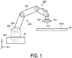
- FIG. 1 is a diagram schematically illustrating a configuration example of a circulation device according to an embodiment.
- FIG. 2 is a diagram schematically illustrating a configuration example of a circulation mechanism of a circulation device according to an embodiment.
- a circulation device 200 includes a base 10, a tank 201, a discharge pump 202, a suction pump 203, a first proportional valve 204, a second proportional valve 205, and a heater 206.
- the circulation device 200 also includes a first pressure sensor 208, a second pressure sensor 209, a third pressure sensor 210, a fourth pressure sensor 211, a liquid droplet discharge head 213, and a robotic portion 220.
- the circulation device 200 having such a configuration controls circulation of the liquid fed from the tank 201 to the liquid droplet discharge head 213.
- the base 10 is placed, for example, on a horizontal floor surface indoors or outdoors.
- the base 10 is provided with the tank 201 that stores liquid. This can prevent rocking of the surface of the liquid stored in the tank 201.
- the robotic portion 220 assembled on the base 10 includes an arm portion 221.
- the arm portion 221 is formed of a plurality of parts that are bent and stretched, and rotatably assembled.
- the arm portion 221 can, for example, move the liquid droplet discharge head 213 mounted on a tip of the arm portion 221 and change the position, posture, and angle of the liquid droplet discharge head 213.
- the arm portion 221 illustrated in FIG. 1 is not particularly limited to the configuration illustrated in FIG. 1 as long as the arm portion 221 is provided with a degree of freedom with which the liquid droplet discharge head 213 can change the movement, position, posture, angle, and the like as necessary.
- the discharge pump 202 and the suction pump 203 are provided on a root side of the arm portion 221 including the robotic portion 220 assembled on the base 10.
- pulsation is likely to be caused by the discharge pump 202 and the suction pump 203.
- the circulation device 200 according to an embodiment includes the first proportional valve 204 and the second proportional valve 205, which are described below, and thereby absorbs the pulsation by the discharge pump 202 and the suction pump 203.
- the first proportional valve 204 is interposed in a first channel RT 1 between the discharge pump 202 and the liquid droplet discharge head 213, and as illustrated in FIG. 1 , is provided on a tip side of the arm portion 221 including the liquid droplet discharge head 213 assembled on the robotic portion 220.
- the second proportional valve 205 is interposed in a second channel RT 2 between the suction pump 203 and the liquid droplet discharge head 213, and as illustrated in FIG. 1 , is provided on the tip side of the arm portion 221 including the liquid droplet discharge head 213 assembled on the robotic portion 220.
- the first proportional valve 204 and the second proportional valve 205 can be mounted on the arm portion 221 by being disposed in a frame member (not illustrated) provided at the tip of the arm portion 221. This strengthens the fixing of the first proportional valve 204 and the second proportional valve 205.
- the first proportional valve 204 and the second proportional valve 205 are mounted on the tip side of the arm portion 221 including the liquid droplet discharge head 213 assembled thereupon, thereby providing a degree of distance between the discharge pump 202 and the suction pump 203, and the liquid droplet discharge head 213.
- the circulation device 200 is less likely to transmit pulsation by the discharge pump 202 and the suction pump 203 to the liquid droplet discharge head 213.
- the circulation device 200 can suppress as much as possible the pulsation that reaches the liquid droplet discharge head 213 by the first proportional valve 204 and the second proportional valve 205.
- the heater 206 is provided, for example, inside the tank 201 and inside the liquid droplet discharge head 213. Note that the heater 206 may be provided adjacent to the tank 201 instead of inside the tank 201 as long as the heat of the heater 206 is transmitted to the tank 201. Likewise, the heater 206 may be provided adjacent to the liquid droplet discharge head 213 instead of inside the liquid droplet discharge head 213 as long as the heat of the heater 206 is transmitted to the liquid droplet discharge head 213. Furthermore, the heater 206 may be provided in either one of the tank 201 and the liquid droplet discharge head 213.
- FIG. 1 illustrates an example in which the discharge pump 202 and the suction pump 203 are mounted on the root side of the arm portion 221 including the robotic portion 220 assembled on the base 10, but the configuration may not be particularly limited to this example.
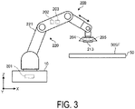
- FIG. 3 is a diagram schematically illustrating a configuration example of a circulation device according to a modified example.
- the circulation device 200 may be provided with the discharge pump 202 and the suction pump 203 at an intermediate position in the vicinity of a midpoint between the tip of the arm portion 221 and the root thereof.
- the discharge pump 202 and the suction pump 203 may be provided at an intermediate position of the arm portion 221, thereby increasing the output efficiency of the pumps compared to a case, as illustrated in FIG. 1 , where the pumps are provided on the root side of the arm portion 221.
- at least one of the discharge pump 202 and the suction pump 203 may be provided at an intermediate position in the vicinity of a midpoint between the tip of the arm portion 221 and the root thereof.
- FIG. 2 explains an example in which the first proportional valve 204 is interposed in the first channel RT 1 between discharge pump 202 and the liquid droplet discharge head 213 and the second proportional valve 205 is interposed in the second channel RT 2 between the suction pump 203 and the liquid droplet discharge head 213.
- the configuration may not be particularly limited to this example.
- a modified example of the mounting positions of the first proportional valve 204 and the second proportional valve 205 will be described below using FIG. 4.
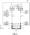
- FIG. 4 is a diagram schematically illustrating a configuration example of a circulation mechanism of a circulation device according to a modified example.
- the first proportional valve 204 and the second proportional valve 205 may be housed inside the liquid droplet discharge head 213. As illustrated in FIG. 4 , the first proportional valve 204 and the second proportional valve 205 may be closer to the liquid droplet discharge head 213 than in the example illustrated in FIG. 2 , thereby improving response to pulsation by the pumps. Note that at least one of the first proportional valve 204 and the second proportional valve 205 may be housed inside the liquid droplet discharge head 213.
- first proportional valve 204 and the second proportional valve 205 are each preferably provided, as illustrated in FIG. 1 , on the tip side of the arm portion 221, but as long as the first proportional valve 204 and the second proportional valve 205 are interposed in the first channel RT 1 and the second channel RT 2 , respectively, an effect of suppressing the transmission of the pulsation to the liquid droplet discharge head 213 can be expected.
- at least one of the first proportional valve 204 and the second proportional valve 205 may be provided on the tip side of the arm portion 221.
- the circulation device 200 may include a single pump that integrates the discharge pump 202 and the suction pump 203 as a mechanism for circulating liquid.
- a proportional valve for controlling the flow rate of the liquid is disposed on a discharge side of the liquid between the discharge pump 202 and the liquid droplet discharge head 213.
- a proportional valve for controlling the flow rate of the liquid is disposed on a recovery side of the liquid between the discharge pump 202 and the liquid droplet discharge head 213.
- the tank 201 and the liquid droplet discharge head 213 may be configured to be heat-resistant. Such a configuration is less susceptible to fluctuations in the outside temperature, and the thermal efficiency of the heater 206 can be expected to improve.
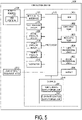
- FIG. 5 is a diagram illustrating an example of a functional configuration of a circulation device according to an embodiment.
- FIG. 5 illustrates an example of a functional configuration of the circulation device 200 according to an embodiment, and the functional configuration of the circulation device 200 should not be particularly limited to the example illustrated in FIG. 5 , provided that the functions of the circulation device 200 according to the embodiment can be realized.
- FIG. 5 illustrates, in functional blocks, components provided in the circulation device 200 according to the embodiment and omits a description of other components in general.
- the components of the circulation device 200 illustrated in FIG. 5 are functional concepts and are not limited to the example illustrated in FIG. 5 , and are not necessarily physically configured as illustrated.
- the specific form of distribution and integration of each of the functional blocks is not limited to that illustrated, and all or a portion thereof can be functionally or physically distributed and integrated in any unit, depending on various loads, usage conditions, and the like.
- the circulation device 200 includes a tank 201, a discharge pump 202, a suction pump 203, a first proportional valve 204, a second proportional valve 205, and a heater 206.
- the circulation device 200 also includes an input/output interface 207, the first pressure sensor 208, the second pressure sensor 209, the third pressure sensor 210, the fourth pressure sensor 211, a flowmeter 212, and the liquid droplet discharge head 213.
- the circulation device 200 further includes a storage 214, a processor 215, and the robotic portion 220.
- the circulation device 200 illustrated in FIG. 5 includes the first channel RT 1 and the second channel RT 2 (see FIG. 2 ).
- the first channel RT 1 is a channel that allows the liquid stored in the tank 201 to flow into the liquid droplet discharge head 213.
- the second channel RT 2 is a channel communicating the tank 201 and the liquid droplet discharge head 300 with each other to allow the liquid that has flowed into the liquid droplet discharge head 213 to return to the tank 201.
- the liquid recovered in the liquid droplet discharge head 300 without being discharged from the liquid droplet discharge head 213 to the outside is sent back through the second channel RT 2 to the tank 201.
- the first channel RT 1 and the second channel RT 2 can be implemented, for example, by a pipe formed of a predetermined material that does not interact with constituents of the liquid.
- the circulation device 200 having such components controls the circulation of the liquid fed from the tank 201 to the liquid droplet discharge head 213.
- the tank 201 stores the liquid supplied to the liquid droplet discharge head 213.
- the tank 201 functions as a storage unit for storing the liquid supplied to the liquid droplet discharge head 213.
- the discharge pump 202 functions as a first pressure applying portion that feeds the liquid stored in the tank 201 to the liquid droplet discharge head 213 through the first channel RT 1 .
- the discharge pump 202 generates positive pressure for feeding the liquid stored in the tank 201 to the liquid droplet discharge head 213.
- the discharge pump 202 feeds the liquid from the tank 201 to the liquid droplet discharge head 213 at a predetermined constant pressure.
- the suction pump 203 functions as a second pressure applying portion that feeds the liquid recovered in the liquid droplet discharge head 213 to the tank 201 through the second channel RT 2 .
- the suction pump 203 generates negative pressure for sucking the liquid from the liquid droplet discharge head 213 and sending the liquid back to the tank 201.
- the suction pump 203 sends the liquid back to the tank 201 from the liquid droplet discharge head 213 at a predetermined constant pressure.
- the discharge pump 202 and the suction pump 203 can be implemented by a rotary pump such as a gear pump or a positive displacement pump such as a diaphragm pump.
- the first proportional valve 204 functions as a first valve portion interposed in the first channel RT 1 between the tank 201 and the liquid droplet discharge head 213.
- the first proportional valve 204 proportionally controls the flow rate of the liquid fed from the tank 201 to the liquid droplet discharge head 213.
- the first proportional valve 204 can continuously modify the channel cross-sectional area for the liquid between 0 to 100%, and controls the flow rate of the liquid to a desired flow rate. For example, the first proportional valve 204 can reduce the channel cross-sectional area of the liquid and thereby suppress the pulsation generated in the liquid by the discharge pump 202.
- the second proportional valve 205 functions as a second valve portion interposed in the second channel RT 2 between the tank 201 and the liquid droplet discharge head 213.
- the second proportional valve 205 proportionally controls the flow rate of the liquid fed from the liquid droplet discharge head 213 to the tank 201.
- the second proportional valve 205 can continuously modify the channel cross-sectional area for the liquid between 0 to 100%, and controls the flow rate of the liquid to a desired flow rate. For example, the second proportional valve 205 can reduce the channel cross-sectional area of the liquid and thereby reduce the pulsation generated in the liquid by the suction pump 203.
- the first proportional valve 204 and the second proportional valve 205 can be implemented by a proportional selector valve of an electromagnetic type or a proportional selector valve of a pneumatic type.
- the heater 206 heats the liquid stored in the tank 201 and the liquid circulating through the liquid droplet discharge head 213.
- the input/output interface 207 exchanges various types of information with the robotic portion 220.
- the input/output interface 207 can transmit a control signal for causing the robotic portion 220 to perform a predetermined operation.
- the first pressure sensor 208 measures, by the discharge pump 202, the fluid pressure of the liquid fed from the tank 201 to the liquid droplet discharge head 213.
- the first pressure sensor 208 measures the pressure downstream of the discharge pump 202 in a circulation direction of the liquid in the circulation device 200.
- the first pressure sensor 208 sends the measurement results to the processor 215.
- the second pressure sensor 209 measures the fluid pressure of the liquid that is sucked from the liquid droplet discharge head 213 by the suction pump 203 and fed to the tank 201.
- the second pressure sensor 209 measures the pressure upstream of the suction pump 203 in the circulation direction of the liquid in the circulation device 200.
- the second pressure sensor 209 sends the measurement results to the processor 215.
- the third pressure sensor 210 measures, through the first channel RT 1 , the fluid pressure of the liquid flowing between the first proportional valve 204 and the liquid droplet discharge head 300.
- the third pressure sensor 210 measures the fluid pressure of the liquid immediately before the liquid flows into the liquid droplet discharge head 213 after passing through the first proportional valve 204. That is, the third pressure sensor 210 measures the fluid pressure downstream of the first proportional valve 204 in the circulation direction of the liquid in the circulation device 200.
- the third pressure sensor 210 sends the measurement results to the processor 215.
- the fourth pressure sensor 211 measures, through the second channel RT 2 , the fluid pressure of the liquid flowing between the second proportional valve 205 and the liquid droplet discharge head 300.
- the fourth pressure sensor 211 measures the fluid pressure of the liquid immediately after being fed from the liquid droplet discharge head 213 toward the tank 201 and before passing through the second proportional valve 205. That is, the fourth pressure sensor 211 measures the pressure upstream of the second proportional valve 205 in the circulation direction of the liquid in the circulation device 200.
- the fourth pressure sensor 211 sends the measurement results to the processor 215.
- the flowmeter 212 measures the flow rate of the liquid fed to the liquid droplet discharge head 213.
- the flowmeter 12 sends the measurement results to the processor 215.
- the liquid droplet discharge head 213 discharges the liquid fed from the tank 201 toward the object 50 illustrated in FIG. 1 .
- the liquid droplet discharge head 213 recovers the liquid that is not discharged and feeds the liquid thus recovered to the tank 201.
- the storage 214 stores programs and data necessary for various processes of the circulation device 200.
- the storage 214 includes, for example, a robot control data storage unit 241, a pump control data storage unit 242, and a flow rate control data storage unit 243.
- the robot control data storage unit 241 stores control programs, data, and the like for controlling the operation of the arm portion 221 included in the robotic portion 220.
- the data stored in the robot control data storage unit 241 stores, for example, data such as an operation procedure for the liquid droplet discharge head 213 and a movement direction, position, posture, and angle during the operation thereof (liquid discharge).
- the pump control data storage unit 242 stores data, set in advance, for pump control.
- the data for pump control includes, for example, a set value of pressure (positive pressure) applied to the liquid that the discharge pump 202 feeds, a set value of pressure (negative pressure) applied to the liquid that the suction pump 203 sucks, and the like.
- the positive pressure of the discharge pump 202 is preset to, for example, a value approximately 1.2 to 3 times higher than the pressure at which the liquid is supplied to the liquid droplet discharge head 213.
- the negative pressure of the suction pump 203 is preset to a value approximately 1.2 to 3 times lower than the pressure at which the liquid is supplied to the liquid droplet discharge head 213.
- the flow rate control data storage unit 243 stores flow rate control data for controlling the flow rate of the liquid circulating between the tank 201 and the liquid droplet discharge head 213.
- FIG. 6 is a diagram illustrating an overview of flow rate control data according to an embodiment.
- the flow rate control data stored in the flow rate control data storage unit 243 includes an item of a control target and an item of a target value, and these items are associated with each other.
- the item of a control target either the first proportional valve 204 or the second proportional valve 205, which is a control target, is registered.
- a target value in controlling the flow rate of the liquid is registered as the target value.
- the target value corresponding to each of the first proportional valve 204 and the second proportional valve 205 may be the same or different. For example, a target value of an average flow rate in a certain time period may be set for each of the first proportional valve 204 and the second proportional valve 205.
- a target value of 50% of the maximum flow rate may be set with respect to the first proportional valve 204, and a target value of an average flow rate in a certain time period may be set with respect to a target value of the second proportional valve 205.
- the processor 215 executes various processes in the circulation device 200 in accordance with programs, data, and the like that are stored in the storage 214.
- the processor 215 implements various functions for controlling the components of the circulation device 200 by reading out and executing the computer program stored in the storage 214.
- the processor 215 controls the operation of the arm portion 221 included in the robotic portion 220 in accordance with control programs, data, or the like that are stored in the robot control data storage unit 241.
- the processor 215 causes the arm portion 221 to execute a desired operation by outputting a command to control the operation of the arm portion 221 to an actuator or the like that drives the arm portion 110.
- the processor 215 makes an adjustment to keep constant the positive pressure applied to the liquid that the discharge pump 202 feeds in accordance with the measurement results of the first pressure sensor 208 and the measurement results of the third pressure sensor 210. For example, the processor 215 adjusts the positive pressure of the discharge pump 202 such that the pressure of the liquid obtained from the measurement results of the first pressure sensor 208 remains approximately 1.2 to 3 times larger than the pressure of the liquid obtained from the measurement results of the measurement results of the third pressure sensor 210.
- the processor 215 also makes an adjustment to keep constant the negative pressure applied to the liquid that the suction pump 203 sucks in accordance with the measurement results of the second pressure sensor 209 and the third pressure sensor 210. For example, the processor 215 adjusts the negative pressure of the suction pump 203 such that the pressure of the liquid obtained from the measurement results of the second pressure sensor 209 remains approximately 1.2 to 3 times lower than the pressure of the liquid obtained from the measurement results of the measurement results of the third pressure sensor 210.
- the processor 215 circulates the liquid between the tank 201 and the liquid droplet discharge head 213 by adjusting and keeping constant the differential pressure between the positive pressure that the discharge pump 202 applies to the liquid and the negative pressure that the suction pump 203 applies to the liquid.
- the processor 215 controls the flow rate of the liquid passing through the first proportional valve 204 and the second proportional valve 205 in accordance with flow rate control data stored in the flow rate control data storage unit 243.
- An example of a method for controlling the flow rate by the processor 215 will be described below using FIG. 7.
- FIG. 7 is a diagram schematically illustrating an example of a relationship between a flow rate of a liquid and time according to an embodiment.
- FIG. 7 schematically illustrates an example of a relationship between: an instantaneous flow rate of the liquid circulating between the tank 201 and the liquid droplet discharge head 213; and time.
- a pulse is generated by liquid supply by the discharge pump 202 and by liquid recovery by the suction pump.
- a target value MV1 has been set for the third pressure sensor 210, the target value MV1 being that a maximum flow rate "Q max " be changed to an average flow rate per time period "Q ave ".
- the processor 15 while referring to the measurement results of the third pressure sensor 210, adjusts the flow rate of the liquid passing through the first proportional valve 204 by narrowing the channel cross-sectional area of the first proportional valve 204 so as to approximate the target value MV1. This allows the processor 215 to control the flow rate of the liquid passing through the first proportional valve 204 and the second proportional valve 205.
- the processor 215 can, by such a control, reduce the pressure of the liquid supplied to the liquid droplet discharge head 213 and suppress pulsation.
- the first proportional valve 204 is interposed in the first channel RT 1 between the discharge pump 202 and the liquid droplet discharge head 213 and disposed, for example, on the tip side of the arm portion 221 including the liquid droplet discharge head 213 assembled on the robotic portion 220.
- the second proportional valve 205 is interposed in the second channel RT 2 between the suction pump 203 and the liquid droplet discharge head 213 and disposed, for example, on the tip side of the arm portion 221 including the liquid droplet discharge head 213 assembled on the robotic portion 220.
- the processor 215 also controls the flow rate of the first proportional valve 204 and the second proportional valve 205 in accordance with the flow rate control data.
- the circulation device 200 can suppress the transmission, to the liquid droplet discharge head 213, of the pulsation caused by the discharge pump 202 and the suction pump 203, and can suppress the pulsation by the discharge pump 202 and the suction pump 203.
- FIG. 8 is a diagram illustrating measurement results of circulation pressure of a liquid during printing according to an embodiment.
- the vertical axis on the left side of FIG. 8 indicates the supply pressure, and the vertical axis on the right side of FIG. 8 indicates the recovery pressure.
- the horizontal axis in FIG. 8 indicates time, and time flows to the right side of FIG. 8 .
- the upper line in the graph region of FIG. 8 indicates a time-series change in the supply pressure
- the lower line in the graph region of FIG. 8 indicates a time-series change in the recovery pressure.
- the supply pressure and the recovery pressure during circulation of the liquid before the liquid is discharged have a substantially constant value. Then, the supply pressure and the recovery pressure of the liquid are reduced together from the start to the completion of continuous liquid discharge that occurs in solid printing. After the completion of the discharge, the supply pressure and the recovery pressure of the liquid begin to increase gradually. The phenomenon of non-discharge of liquid or the like occurs when the discharge of liquid resumes with the supply pressure and the recovery pressure being still not fully recovered.
- the applicant of the present application infers a mechanism that causes the phenomenon of non-discharge of liquid as follows. Even after the completion of discharge, the liquid continues to flow from the supply side toward the recovery side, but when the recovery pressure is reduced, the second proportional valve 205 is configured to be closed. The applicant of the present application infers that this causes water-hammering action (water hammer) by the liquid that is not discharged and has lost an outlet, resulting in leakage of the liquid from the nozzle and the non-discharge thereof.
- the applicant of the present application solves the above-described problem by causing the processor 215 of the circulation device 200 to execute a control method as described below.
- the applicant of the present application has gained the insight that when a time t x has elapsed after the completion of liquid discharge, the recovery pressure recovers to a set value in a steady state (e. g., liquid circulation). In the example illustrated in FIG. 8 , approximately 0.5 [msec (milliseconds)] after the completion of discharge, the recovery pressure recovers to approximately -10 kPa (kilopascals), which is an initial value at the time of liquid discharge.
- the processor 215 is configured to execute control on the basis of this insight.
- the processor 215 performs control to tighten the first proportional valve 204 on the supply side of the liquid, and to tighten the second proportional valve 205 after a predetermined amount of time elapses.
- the second proportional valve 205 on the recovery side of the liquid is left open at least until the predetermined amount of time elapses, and the liquid can flow to the recovery side. This can prevent the non-discharge of liquid due to the water-hammering action or the leakage of liquid.
- the processor 215 may control the pressure on the recovery side recovering the liquid such that the pressure is lower than the set value in the steady state.
- the force pulling the liquid from the recovery side of the liquid can be increased, and the liquid flows efficiently to the recovery side. This can prevent the non-discharge of liquid due to the water-hammering action or the leakage of liquid.
- the processor 215 may control the pressure on the recovery side recovering the liquid such that the pressure is lower by the amount of the pressure drop due to the discharge of the liquid.
- the pressure drop on the recovery side is approximately 2 [kPa (kilopascals)], and it is only required that the processor 215 control the pressure on the recovery side recovering the liquid after the completion of the liquid discharge such that the pressure is lower by 2 [kPa (kilopascals)], which is generated by the discharge of the liquid. This can prevent the non-discharge of liquid due to the water-hammering action and the leakage of liquid in the same manner as the control to tighten the second proportional valve 205.
- the tank 201 may or may not be provided in the base 10, or may be provided at a location other than in the robotic portion 220. Also, the discharge pump 202 and the suction pump 203 may be provided in the base 10.
Landscapes
- Engineering & Computer Science (AREA)
- Physics & Mathematics (AREA)
- Chemical & Material Sciences (AREA)
- Analytical Chemistry (AREA)
- Robotics (AREA)
- Fluid Mechanics (AREA)
- Manufacturing & Machinery (AREA)
- General Physics & Mathematics (AREA)
- Automation & Control Theory (AREA)
- Coating Apparatus (AREA)
- Ink Jet (AREA)
- Spray Control Apparatus (AREA)
Abstract
Description
- The disclosed embodiments relate to a circulation device.
- Inkjet printers and inkjet plotters that utilize an inkjet recording method are known as printing apparatuses. A liquid discharge head for discharging liquid is mounted in printing apparatuses using such an inkjet method.
- In addition, in a device that discharges liquid, such as an inkjet printing apparatus, a technique for controlling discharge of liquid, a technique for preventing waste of liquid being discharged, a technique for efficiently replacing liquid, and the like have been proposed.
-
- Patent Document 1:
JP 2009-226313 A - Patent Document 2:
JP 2015-167934 A - Patent Document 3:
JP 4235631 B - A circulation device according to an aspect of an embodiment includes a storage unit that stores liquid and a liquid droplet discharge unit that discharges liquid, and controls circulation of liquid fed from the storage unit to the liquid droplet discharge unit. Such a circulation device includes a robotic portion, a first pressure applying portion, a second pressure applying portion, a first valve portion, and a second valve portion. The robotic portion is mounted with the liquid droplet discharge unit. The first pressure applying portion feeds the liquid stored in the storage unit to the liquid droplet discharge unit through a first channel communicating the storage unit and the liquid droplet discharge unit with each other. The second pressure applying portion feeds the liquid recovered in the liquid droplet discharge unit to the storage unit through a second channel communicating the storage unit and the liquid droplet discharge unit with each other. The first valve portion is interposed between the first pressure applying portion and the liquid droplet discharge unit. The second valve portion is interposed between the second pressure applying portion and the liquid droplet discharge unit.
-
-
FIG. 1 is a diagram schematically illustrating a configuration example of a circulation device according to an embodiment. -
FIG. 2 is a diagram schematically illustrating a configuration example of a circulation mechanism of a circulation device according to an embodiment. -
FIG. 3 is a diagram schematically illustrating a configuration example of a circulation device according to a modified example. -
FIG. 4 is a diagram schematically illustrating a configuration example of a circulation mechanism of a circulation device according to a modified example. -
FIG. 5 is a diagram illustrating an example of a functional configuration of a circulation device according to an embodiment. -
FIG. 6 is a diagram illustrating an overview of flow rate control data according to an embodiment. -
FIG. 7 is a diagram schematically illustrating an example of a relationship between a flow rate of a liquid and time according to an embodiment. -
FIG. 8 is a diagram illustrating measurement results of circulation pressure of a liquid during printing according to an embodiment. - Embodiments of a circulation device disclosed in the present application will be described in detail below with reference to the accompanying drawings. Note that the invention according to the present application is not limited to the embodiments that will be described below.
- The circulation device disclosed in the present application can be applied to inkjet printers and inkjet plotters that each utilize an inkjet recording method as well as devices that each discharge liquid droplets in an inkjet method.
- A configuration of a circulation device according to an embodiment will be described using
FIGS. 1 and2 .FIG. 1 is a diagram schematically illustrating a configuration example of a circulation device according to an embodiment.FIG. 2 is a diagram schematically illustrating a configuration example of a circulation mechanism of a circulation device according to an embodiment. - As illustrated in
FIG. 1 or2 , acirculation device 200 includes abase 10, atank 201, adischarge pump 202, asuction pump 203, a firstproportional valve 204, a secondproportional valve 205, and aheater 206. As illustrated inFIG. 1 or2 , thecirculation device 200 also includes afirst pressure sensor 208, asecond pressure sensor 209, athird pressure sensor 210, afourth pressure sensor 211, a liquiddroplet discharge head 213, and arobotic portion 220. As illustrated inFIG. 2 , thecirculation device 200 having such a configuration controls circulation of the liquid fed from thetank 201 to the liquiddroplet discharge head 213. - The
base 10 is placed, for example, on a horizontal floor surface indoors or outdoors. Thebase 10 is provided with thetank 201 that stores liquid. This can prevent rocking of the surface of the liquid stored in thetank 201. - The
robotic portion 220 assembled on thebase 10 includes anarm portion 221. Thearm portion 221 is formed of a plurality of parts that are bent and stretched, and rotatably assembled. In accordance with a predetermined command, thearm portion 221 can, for example, move the liquiddroplet discharge head 213 mounted on a tip of thearm portion 221 and change the position, posture, and angle of the liquiddroplet discharge head 213. Thearm portion 221 illustrated inFIG. 1 is not particularly limited to the configuration illustrated inFIG. 1 as long as thearm portion 221 is provided with a degree of freedom with which the liquiddroplet discharge head 213 can change the movement, position, posture, angle, and the like as necessary. - The
discharge pump 202 and thesuction pump 203 are provided on a root side of thearm portion 221 including therobotic portion 220 assembled on thebase 10. In thecirculation device 200, pulsation is likely to be caused by thedischarge pump 202 and thesuction pump 203. Thecirculation device 200 according to an embodiment includes the firstproportional valve 204 and the secondproportional valve 205, which are described below, and thereby absorbs the pulsation by thedischarge pump 202 and thesuction pump 203. - The first
proportional valve 204, as illustrated inFIG. 2 , is interposed in a first channel RT1 between thedischarge pump 202 and the liquiddroplet discharge head 213, and as illustrated inFIG. 1 , is provided on a tip side of thearm portion 221 including the liquiddroplet discharge head 213 assembled on therobotic portion 220. The secondproportional valve 205, as illustrated inFIG. 2 , is interposed in a second channel RT2 between thesuction pump 203 and the liquiddroplet discharge head 213, and as illustrated inFIG. 1 , is provided on the tip side of thearm portion 221 including the liquiddroplet discharge head 213 assembled on therobotic portion 220. The firstproportional valve 204 and the secondproportional valve 205 can be mounted on thearm portion 221 by being disposed in a frame member (not illustrated) provided at the tip of thearm portion 221. This strengthens the fixing of the firstproportional valve 204 and the secondproportional valve 205. - Additionally, the first
proportional valve 204 and the secondproportional valve 205 are mounted on the tip side of thearm portion 221 including the liquiddroplet discharge head 213 assembled thereupon, thereby providing a degree of distance between thedischarge pump 202 and thesuction pump 203, and the liquiddroplet discharge head 213. Thus, thecirculation device 200 is less likely to transmit pulsation by thedischarge pump 202 and thesuction pump 203 to the liquiddroplet discharge head 213. Furthermore, thecirculation device 200 can suppress as much as possible the pulsation that reaches the liquiddroplet discharge head 213 by the firstproportional valve 204 and the secondproportional valve 205. - The
heater 206 is provided, for example, inside thetank 201 and inside the liquiddroplet discharge head 213. Note that theheater 206 may be provided adjacent to thetank 201 instead of inside thetank 201 as long as the heat of theheater 206 is transmitted to thetank 201. Likewise, theheater 206 may be provided adjacent to the liquiddroplet discharge head 213 instead of inside the liquiddroplet discharge head 213 as long as the heat of theheater 206 is transmitted to the liquiddroplet discharge head 213. Furthermore, theheater 206 may be provided in either one of thetank 201 and the liquiddroplet discharge head 213. -
FIG. 1 illustrates an example in which thedischarge pump 202 and thesuction pump 203 are mounted on the root side of thearm portion 221 including therobotic portion 220 assembled on thebase 10, but the configuration may not be particularly limited to this example. A modified example of the mounting positions of thedischarge pump 202 and thesuction pump 203 will be described usingFIG. 3. FIG. 3 is a diagram schematically illustrating a configuration example of a circulation device according to a modified example. - For example, as illustrated in
FIG. 3 , thecirculation device 200 may be provided with thedischarge pump 202 and thesuction pump 203 at an intermediate position in the vicinity of a midpoint between the tip of thearm portion 221 and the root thereof. As illustrated inFIG. 3 , thedischarge pump 202 and thesuction pump 203 may be provided at an intermediate position of thearm portion 221, thereby increasing the output efficiency of the pumps compared to a case, as illustrated inFIG. 1 , where the pumps are provided on the root side of thearm portion 221. Note that at least one of thedischarge pump 202 and thesuction pump 203 may be provided at an intermediate position in the vicinity of a midpoint between the tip of thearm portion 221 and the root thereof. -
FIG. 2 explains an example in which the firstproportional valve 204 is interposed in the first channel RT1 betweendischarge pump 202 and the liquiddroplet discharge head 213 and the secondproportional valve 205 is interposed in the second channel RT2 between thesuction pump 203 and the liquiddroplet discharge head 213. However, the configuration may not be particularly limited to this example. A modified example of the mounting positions of the firstproportional valve 204 and the secondproportional valve 205 will be described below usingFIG. 4. FIG. 4 is a diagram schematically illustrating a configuration example of a circulation mechanism of a circulation device according to a modified example. - As illustrated in
FIG. 4 , the firstproportional valve 204 and the secondproportional valve 205 may be housed inside the liquiddroplet discharge head 213. As illustrated inFIG. 4 , the firstproportional valve 204 and the secondproportional valve 205 may be closer to the liquiddroplet discharge head 213 than in the example illustrated inFIG. 2 , thereby improving response to pulsation by the pumps. Note that at least one of the firstproportional valve 204 and the secondproportional valve 205 may be housed inside the liquiddroplet discharge head 213. - Additionally, the first
proportional valve 204 and the secondproportional valve 205 are each preferably provided, as illustrated inFIG. 1 , on the tip side of thearm portion 221, but as long as the firstproportional valve 204 and the secondproportional valve 205 are interposed in the first channel RT1 and the second channel RT2, respectively, an effect of suppressing the transmission of the pulsation to the liquiddroplet discharge head 213 can be expected. Note that at least one of the firstproportional valve 204 and the secondproportional valve 205 may be provided on the tip side of thearm portion 221. - Furthermore, the
circulation device 200 may include a single pump that integrates thedischarge pump 202 and thesuction pump 203 as a mechanism for circulating liquid. Also, a proportional valve for controlling the flow rate of the liquid is disposed on a discharge side of the liquid between thedischarge pump 202 and the liquiddroplet discharge head 213. Alternatively, a proportional valve for controlling the flow rate of the liquid is disposed on a recovery side of the liquid between thedischarge pump 202 and the liquiddroplet discharge head 213. Thus, even in a configuration including the pump that integrates thedischarge pump 202 and thesuction pump 203, the pulsation caused by the pump is less likely to be transferred to the liquiddroplet discharge head 213. - Also, the
tank 201 and the liquiddroplet discharge head 213 may be configured to be heat-resistant. Such a configuration is less susceptible to fluctuations in the outside temperature, and the thermal efficiency of theheater 206 can be expected to improve. - An example of a functional configuration of the
circulation device 200 according to an embodiment will be described usingFIG. 5. FIG. 5 is a diagram illustrating an example of a functional configuration of a circulation device according to an embodiment. - Note that
FIG. 5 illustrates an example of a functional configuration of thecirculation device 200 according to an embodiment, and the functional configuration of thecirculation device 200 should not be particularly limited to the example illustrated inFIG. 5 , provided that the functions of thecirculation device 200 according to the embodiment can be realized. In addition,FIG. 5 illustrates, in functional blocks, components provided in thecirculation device 200 according to the embodiment and omits a description of other components in general. Moreover, the components of thecirculation device 200 illustrated inFIG. 5 are functional concepts and are not limited to the example illustrated inFIG. 5 , and are not necessarily physically configured as illustrated. For example, the specific form of distribution and integration of each of the functional blocks is not limited to that illustrated, and all or a portion thereof can be functionally or physically distributed and integrated in any unit, depending on various loads, usage conditions, and the like. - As illustrated in
FIG. 5 , thecirculation device 200 includes atank 201, adischarge pump 202, asuction pump 203, a firstproportional valve 204, a secondproportional valve 205, and aheater 206. Thecirculation device 200 also includes an input/output interface 207, thefirst pressure sensor 208, thesecond pressure sensor 209, thethird pressure sensor 210, thefourth pressure sensor 211, aflowmeter 212, and the liquiddroplet discharge head 213. Thecirculation device 200 further includes astorage 214, aprocessor 215, and therobotic portion 220. - The
circulation device 200 illustrated inFIG. 5 includes the first channel RT1 and the second channel RT2 (seeFIG. 2 ). The first channel RT1 is a channel that allows the liquid stored in thetank 201 to flow into the liquiddroplet discharge head 213. The second channel RT2 is a channel communicating thetank 201 and the liquid droplet discharge head 300 with each other to allow the liquid that has flowed into the liquiddroplet discharge head 213 to return to thetank 201. The liquid recovered in the liquid droplet discharge head 300 without being discharged from the liquiddroplet discharge head 213 to the outside is sent back through the second channel RT2 to thetank 201. The first channel RT1 and the second channel RT2 can be implemented, for example, by a pipe formed of a predetermined material that does not interact with constituents of the liquid. Thecirculation device 200 having such components controls the circulation of the liquid fed from thetank 201 to the liquiddroplet discharge head 213. - The
tank 201 stores the liquid supplied to the liquiddroplet discharge head 213. Thetank 201 functions as a storage unit for storing the liquid supplied to the liquiddroplet discharge head 213. - The
discharge pump 202 functions as a first pressure applying portion that feeds the liquid stored in thetank 201 to the liquiddroplet discharge head 213 through the first channel RT1. Thedischarge pump 202 generates positive pressure for feeding the liquid stored in thetank 201 to the liquiddroplet discharge head 213. Thedischarge pump 202 feeds the liquid from thetank 201 to the liquiddroplet discharge head 213 at a predetermined constant pressure. - The
suction pump 203 functions as a second pressure applying portion that feeds the liquid recovered in the liquiddroplet discharge head 213 to thetank 201 through the second channel RT2. Thesuction pump 203 generates negative pressure for sucking the liquid from the liquiddroplet discharge head 213 and sending the liquid back to thetank 201. Thesuction pump 203 sends the liquid back to thetank 201 from the liquiddroplet discharge head 213 at a predetermined constant pressure. - The
discharge pump 202 and thesuction pump 203 can be implemented by a rotary pump such as a gear pump or a positive displacement pump such as a diaphragm pump. - The first
proportional valve 204 functions as a first valve portion interposed in the first channel RT1 between thetank 201 and the liquiddroplet discharge head 213. The firstproportional valve 204 proportionally controls the flow rate of the liquid fed from thetank 201 to the liquiddroplet discharge head 213. The firstproportional valve 204 can continuously modify the channel cross-sectional area for the liquid between 0 to 100%, and controls the flow rate of the liquid to a desired flow rate. For example, the firstproportional valve 204 can reduce the channel cross-sectional area of the liquid and thereby suppress the pulsation generated in the liquid by thedischarge pump 202. - The second
proportional valve 205 functions as a second valve portion interposed in the second channel RT2 between thetank 201 and the liquiddroplet discharge head 213. The secondproportional valve 205 proportionally controls the flow rate of the liquid fed from the liquiddroplet discharge head 213 to thetank 201. The secondproportional valve 205 can continuously modify the channel cross-sectional area for the liquid between 0 to 100%, and controls the flow rate of the liquid to a desired flow rate. For example, the secondproportional valve 205 can reduce the channel cross-sectional area of the liquid and thereby reduce the pulsation generated in the liquid by thesuction pump 203. - The first
proportional valve 204 and the secondproportional valve 205 can be implemented by a proportional selector valve of an electromagnetic type or a proportional selector valve of a pneumatic type. - The
heater 206 heats the liquid stored in thetank 201 and the liquid circulating through the liquiddroplet discharge head 213. - The input/
output interface 207 exchanges various types of information with therobotic portion 220. The input/output interface 207 can transmit a control signal for causing therobotic portion 220 to perform a predetermined operation. - The
first pressure sensor 208 measures, by thedischarge pump 202, the fluid pressure of the liquid fed from thetank 201 to the liquiddroplet discharge head 213. Thefirst pressure sensor 208 measures the pressure downstream of thedischarge pump 202 in a circulation direction of the liquid in thecirculation device 200. Thefirst pressure sensor 208 sends the measurement results to theprocessor 215. - The
second pressure sensor 209 measures the fluid pressure of the liquid that is sucked from the liquiddroplet discharge head 213 by thesuction pump 203 and fed to thetank 201. Thesecond pressure sensor 209 measures the pressure upstream of thesuction pump 203 in the circulation direction of the liquid in thecirculation device 200. Thesecond pressure sensor 209 sends the measurement results to theprocessor 215. - The
third pressure sensor 210 measures, through the first channel RT1, the fluid pressure of the liquid flowing between the firstproportional valve 204 and the liquid droplet discharge head 300. Thethird pressure sensor 210 measures the fluid pressure of the liquid immediately before the liquid flows into the liquiddroplet discharge head 213 after passing through the firstproportional valve 204. That is, thethird pressure sensor 210 measures the fluid pressure downstream of the firstproportional valve 204 in the circulation direction of the liquid in thecirculation device 200. Thethird pressure sensor 210 sends the measurement results to theprocessor 215. - The
fourth pressure sensor 211 measures, through the second channel RT2, the fluid pressure of the liquid flowing between the secondproportional valve 205 and the liquid droplet discharge head 300. Thefourth pressure sensor 211 measures the fluid pressure of the liquid immediately after being fed from the liquiddroplet discharge head 213 toward thetank 201 and before passing through the secondproportional valve 205. That is, thefourth pressure sensor 211 measures the pressure upstream of the secondproportional valve 205 in the circulation direction of the liquid in thecirculation device 200. Thefourth pressure sensor 211 sends the measurement results to theprocessor 215. - The
flowmeter 212 measures the flow rate of the liquid fed to the liquiddroplet discharge head 213. Theflowmeter 12 sends the measurement results to theprocessor 215. - The liquid
droplet discharge head 213 discharges the liquid fed from thetank 201 toward theobject 50 illustrated inFIG. 1 . The liquiddroplet discharge head 213 recovers the liquid that is not discharged and feeds the liquid thus recovered to thetank 201. - The
storage 214 stores programs and data necessary for various processes of thecirculation device 200. Thestorage 214 includes, for example, a robot controldata storage unit 241, a pump controldata storage unit 242, and a flow rate control data storage unit 243. - The robot control
data storage unit 241 stores control programs, data, and the like for controlling the operation of thearm portion 221 included in therobotic portion 220. The data stored in the robot controldata storage unit 241 stores, for example, data such as an operation procedure for the liquiddroplet discharge head 213 and a movement direction, position, posture, and angle during the operation thereof (liquid discharge). - The pump control
data storage unit 242 stores data, set in advance, for pump control. The data for pump control includes, for example, a set value of pressure (positive pressure) applied to the liquid that thedischarge pump 202 feeds, a set value of pressure (negative pressure) applied to the liquid that thesuction pump 203 sucks, and the like. When considering the discharge of liquid from the liquiddroplet discharge head 213, the positive pressure of thedischarge pump 202 is preset to, for example, a value approximately 1.2 to 3 times higher than the pressure at which the liquid is supplied to the liquiddroplet discharge head 213. In contrast, the negative pressure of thesuction pump 203 is preset to a value approximately 1.2 to 3 times lower than the pressure at which the liquid is supplied to the liquiddroplet discharge head 213. - The flow rate control data storage unit 243 stores flow rate control data for controlling the flow rate of the liquid circulating between the
tank 201 and the liquiddroplet discharge head 213.FIG. 6 is a diagram illustrating an overview of flow rate control data according to an embodiment. - As illustrated in
FIG. 6 , the flow rate control data stored in the flow rate control data storage unit 243 includes an item of a control target and an item of a target value, and these items are associated with each other. In the item of a control target, either the firstproportional valve 204 or the secondproportional valve 205, which is a control target, is registered. A target value in controlling the flow rate of the liquid is registered as the target value. Note that the target value corresponding to each of the firstproportional valve 204 and the secondproportional valve 205 may be the same or different. For example, a target value of an average flow rate in a certain time period may be set for each of the firstproportional valve 204 and the secondproportional valve 205. Further, for example, a target value of 50% of the maximum flow rate may be set with respect to the firstproportional valve 204, and a target value of an average flow rate in a certain time period may be set with respect to a target value of the secondproportional valve 205. - The
processor 215 executes various processes in thecirculation device 200 in accordance with programs, data, and the like that are stored in thestorage 214. Theprocessor 215 implements various functions for controlling the components of thecirculation device 200 by reading out and executing the computer program stored in thestorage 214. - The
processor 215 controls the operation of thearm portion 221 included in therobotic portion 220 in accordance with control programs, data, or the like that are stored in the robot controldata storage unit 241. Theprocessor 215 causes thearm portion 221 to execute a desired operation by outputting a command to control the operation of thearm portion 221 to an actuator or the like that drives the arm portion 110. - The
processor 215 makes an adjustment to keep constant the positive pressure applied to the liquid that thedischarge pump 202 feeds in accordance with the measurement results of thefirst pressure sensor 208 and the measurement results of thethird pressure sensor 210. For example, theprocessor 215 adjusts the positive pressure of thedischarge pump 202 such that the pressure of the liquid obtained from the measurement results of thefirst pressure sensor 208 remains approximately 1.2 to 3 times larger than the pressure of the liquid obtained from the measurement results of the measurement results of thethird pressure sensor 210. - The
processor 215 also makes an adjustment to keep constant the negative pressure applied to the liquid that thesuction pump 203 sucks in accordance with the measurement results of thesecond pressure sensor 209 and thethird pressure sensor 210. For example, theprocessor 215 adjusts the negative pressure of thesuction pump 203 such that the pressure of the liquid obtained from the measurement results of thesecond pressure sensor 209 remains approximately 1.2 to 3 times lower than the pressure of the liquid obtained from the measurement results of the measurement results of thethird pressure sensor 210. - The
processor 215 circulates the liquid between thetank 201 and the liquiddroplet discharge head 213 by adjusting and keeping constant the differential pressure between the positive pressure that thedischarge pump 202 applies to the liquid and the negative pressure that thesuction pump 203 applies to the liquid. - The
processor 215 controls the flow rate of the liquid passing through the firstproportional valve 204 and the secondproportional valve 205 in accordance with flow rate control data stored in the flow rate control data storage unit 243. An example of a method for controlling the flow rate by theprocessor 215 will be described below usingFIG. 7. FIG. 7 is a diagram schematically illustrating an example of a relationship between a flow rate of a liquid and time according to an embodiment. -
FIG. 7 schematically illustrates an example of a relationship between: an instantaneous flow rate of the liquid circulating between thetank 201 and the liquiddroplet discharge head 213; and time. As illustrated inFIG. 7 , in the liquid circulating between thetank 201 and the liquiddroplet discharge head 213, a pulse is generated by liquid supply by thedischarge pump 202 and by liquid recovery by the suction pump. - Suppose, for example, that in the flow rate control data, a target value MV1 has been set for the
third pressure sensor 210, the target value MV1 being that a maximum flow rate "Qmax" be changed to an average flow rate per time period "Qave". The processor 15, while referring to the measurement results of thethird pressure sensor 210, adjusts the flow rate of the liquid passing through the firstproportional valve 204 by narrowing the channel cross-sectional area of the firstproportional valve 204 so as to approximate the target value MV1. This allows theprocessor 215 to control the flow rate of the liquid passing through the firstproportional valve 204 and the secondproportional valve 205. Theprocessor 215 can, by such a control, reduce the pressure of the liquid supplied to the liquiddroplet discharge head 213 and suppress pulsation. - The first
proportional valve 204 is interposed in the first channel RT1 between thedischarge pump 202 and the liquiddroplet discharge head 213 and disposed, for example, on the tip side of thearm portion 221 including the liquiddroplet discharge head 213 assembled on therobotic portion 220. The secondproportional valve 205 is interposed in the second channel RT2 between thesuction pump 203 and the liquiddroplet discharge head 213 and disposed, for example, on the tip side of thearm portion 221 including the liquiddroplet discharge head 213 assembled on therobotic portion 220. Theprocessor 215 also controls the flow rate of the firstproportional valve 204 and the secondproportional valve 205 in accordance with the flow rate control data. Thus, thecirculation device 200 according to the embodiment can suppress the transmission, to the liquiddroplet discharge head 213, of the pulsation caused by thedischarge pump 202 and thesuction pump 203, and can suppress the pulsation by thedischarge pump 202 and thesuction pump 203. - In addition, the applicant of the present application has discovered a phenomenon in which, in a printing operation using the above-described
circulation device 200, correct printing is not performed due to non-discharge of liquid (ink) or leakage of liquid occurs from the liquiddroplet discharge head 213 after solid printing in which liquid is continuously discharged.FIG. 8 is a diagram illustrating measurement results of circulation pressure of a liquid during printing according to an embodiment. The vertical axis on the left side ofFIG. 8 indicates the supply pressure, and the vertical axis on the right side ofFIG. 8 indicates the recovery pressure. The horizontal axis inFIG. 8 indicates time, and time flows to the right side ofFIG. 8 . The upper line in the graph region ofFIG. 8 indicates a time-series change in the supply pressure, and the lower line in the graph region ofFIG. 8 indicates a time-series change in the recovery pressure. - As illustrated in
FIG. 8 , the supply pressure and the recovery pressure during circulation of the liquid before the liquid is discharged have a substantially constant value. Then, the supply pressure and the recovery pressure of the liquid are reduced together from the start to the completion of continuous liquid discharge that occurs in solid printing. After the completion of the discharge, the supply pressure and the recovery pressure of the liquid begin to increase gradually. The phenomenon of non-discharge of liquid or the like occurs when the discharge of liquid resumes with the supply pressure and the recovery pressure being still not fully recovered. - The applicant of the present application infers a mechanism that causes the phenomenon of non-discharge of liquid as follows. Even after the completion of discharge, the liquid continues to flow from the supply side toward the recovery side, but when the recovery pressure is reduced, the second
proportional valve 205 is configured to be closed. The applicant of the present application infers that this causes water-hammering action (water hammer) by the liquid that is not discharged and has lost an outlet, resulting in leakage of the liquid from the nozzle and the non-discharge thereof. Thus, the applicant of the present application solves the above-described problem by causing theprocessor 215 of thecirculation device 200 to execute a control method as described below. - As illustrated in
FIG. 8 , the applicant of the present application has gained the insight that when a time tx has elapsed after the completion of liquid discharge, the recovery pressure recovers to a set value in a steady state (e. g., liquid circulation). In the example illustrated inFIG. 8 , approximately 0.5 [msec (milliseconds)] after the completion of discharge, the recovery pressure recovers to approximately -10 kPa (kilopascals), which is an initial value at the time of liquid discharge. Thus, theprocessor 215 is configured to execute control on the basis of this insight. Specifically, after the completion of liquid discharge, theprocessor 215 performs control to tighten the firstproportional valve 204 on the supply side of the liquid, and to tighten the secondproportional valve 205 after a predetermined amount of time elapses. Thus, the secondproportional valve 205 on the recovery side of the liquid is left open at least until the predetermined amount of time elapses, and the liquid can flow to the recovery side. This can prevent the non-discharge of liquid due to the water-hammering action or the leakage of liquid. - In addition, upon the completion of the discharge of liquid from the liquid
droplet discharge head 213, theprocessor 215 may control the pressure on the recovery side recovering the liquid such that the pressure is lower than the set value in the steady state. Thus, the force pulling the liquid from the recovery side of the liquid can be increased, and the liquid flows efficiently to the recovery side. This can prevent the non-discharge of liquid due to the water-hammering action or the leakage of liquid. - Additionally, upon the completion of the discharge of the liquid from the liquid
droplet discharge head 213, theprocessor 215 may control the pressure on the recovery side recovering the liquid such that the pressure is lower by the amount of the pressure drop due to the discharge of the liquid. In the example illustrated inFIG. 8 , the pressure drop on the recovery side is approximately 2 [kPa (kilopascals)], and it is only required that theprocessor 215 control the pressure on the recovery side recovering the liquid after the completion of the liquid discharge such that the pressure is lower by 2 [kPa (kilopascals)], which is generated by the discharge of the liquid. This can prevent the non-discharge of liquid due to the water-hammering action and the leakage of liquid in the same manner as the control to tighten the secondproportional valve 205. - Embodiments have been described in order to fully and clearly disclose the technology according to the appended claims. However, the appended claims are not to be limited to the embodiments described above, and should be configured to embody all modified examples and alternative configurations that a person skilled in the art may make within the fundamental matter set forth in the present description.
- Note that the
tank 201 may or may not be provided in thebase 10, or may be provided at a location other than in therobotic portion 220. Also, thedischarge pump 202 and thesuction pump 203 may be provided in thebase 10. -
- 10 Base portion
- 50 Object
- 200 Circulation device
- 201 Tank
- 202 Discharge pump
- 203 Suction pump
- 204 First proportional valve
- 205 Second proportional valve
- 206 Heater
- 207 Input/output interface
- 208 First pressure sensor
- 209 Second pressure sensor
- 210 Third pressure sensor
- 211 Fourth pressure sensor
- 212 Flowmeter
- 213 Liquid droplet discharge head
- 214 Storage
- 215 Processor
- 220 Robotic portion
- 221 Arm portion
- 241 Robot control data storage unit
- 242 Pump control data storage unit
- 243 Flow rate control data storage unit
Claims (10)
- A circulation device for controlling circulation of a liquid that is fed from a storage unit to a liquid droplet discharge unit, the circulation device comprising:a storage unit configured to store a liquid;a liquid droplet discharge unit configured to discharge the liquid;a robotic portion mounted with the liquid droplet discharge unit;a first pressure applying portion configured to feed the liquid stored in the storage unit to the liquid droplet discharge unit through a first channel configured to communicate the storage unit and the liquid droplet discharge unit with each other;a second pressure applying portion configured to feed the liquid recovered in the liquid droplet discharge unit to the storage unit through a second channel configured to communicate the storage unit and the liquid droplet discharge unit with each other;a first valve portion interposed between the first pressure applying portion and the liquid droplet discharge unit; anda second valve portion interposed between the second pressure applying portion and the liquid droplet discharge unit.
- The circulation device according to claim 1, whereinthe robotic portion comprises an arm portion that is freely operable,the first pressure applying portion is provided on a root side of the arm portion comprising the robotic portion assembled on a base, andthe first valve portion is provided on a tip side of the arm portion comprising the liquid droplet discharge unit assembled on the robotic portion.
- The circulation device according to claim 1 or 2, whereinthe robotic portion comprises an arm portion that is freely operable,the second pressure applying portion is provided on a root side of the arm portion comprising the robotic portion assembled on a base, andthe second valve portion is provided on a tip side of the arm portion comprising the liquid droplet discharge unit assembled on the robotic portion.
- The circulation device according to claim 1, whereinthe robotic portion comprises an arm portion that is freely operable,the first pressure applying portion is provided at an intermediate position of the arm portion, andthe first valve portion is provided on a tip side of the arm portion comprising the liquid droplet discharge unit mounted on the robotic portion.
- The circulation device according to claim 1 or 4, whereinthe robotic portion comprises an arm portion that is freely operable,the second pressure applying portion is provided at an intermediate position of the arm portion, andthe second valve portion is provided on a tip side of the arm portion comprising the liquid droplet discharge unit mounted on the robotic portion.
- The circulation device according to claim 1, wherein at least one of the first valve portion and the second valve portion is housed inside the liquid droplet discharge unit.
- The circulation device according to any one of claims 1 to 6, further comprising a heater unit configured to heat the liquid stored in the storage unit.
- The circulation device according to claim 1, wherein a processor for controlling components of the circulation device is configured to perform control to tighten the second valve portion after a predetermined amount of time has elapsed following completion of the discharge of the liquid from the liquid droplet discharge unit.
- The circulation device according to claim 1, wherein a processor for controlling components of the circulation device is configured to control a pressure on a recovery side recovering the liquid upon completion of the discharge of the liquid from the liquid droplet discharge unit to cause the pressure to be smaller than a set value in a steady state.
- The circulation device according to claim 9, wherein the processor for controlling components of the circulation device controls the pressure on the recovery side recovering the liquid upon the completion of the discharge of the liquid from the liquid droplet discharge unit to cause the pressure to be lower by an amount of a pressure drop caused by the discharge of the liquid.
Applications Claiming Priority (2)
| Application Number | Priority Date | Filing Date | Title |
|---|---|---|---|
| JP2019159116 | 2019-08-30 | ||
| PCT/JP2020/032777 WO2021040034A1 (en) | 2019-08-30 | 2020-08-28 | Circulation device |
Publications (3)
| Publication Number | Publication Date |
|---|---|
| EP4023346A1 true EP4023346A1 (en) | 2022-07-06 |
| EP4023346A4 EP4023346A4 (en) | 2023-09-20 |
| EP4023346B1 EP4023346B1 (en) | 2025-08-20 |
Family
ID=74685629
Family Applications (1)
| Application Number | Title | Priority Date | Filing Date |
|---|---|---|---|
| EP20858425.0A Active EP4023346B1 (en) | 2019-08-30 | 2020-08-28 | Circulation device |
Country Status (5)
| Country | Link |
|---|---|
| US (2) | US12257850B2 (en) |
| EP (1) | EP4023346B1 (en) |
| JP (3) | JP7368481B2 (en) |
| CN (3) | CN116483145A (en) |
| WO (1) | WO2021040034A1 (en) |
Families Citing this family (6)
| Publication number | Priority date | Publication date | Assignee | Title |
|---|---|---|---|---|
| JP7516873B2 (en) * | 2020-06-01 | 2024-07-17 | セイコーエプソン株式会社 | 3D object printing device |
| JP7169476B1 (en) | 2022-03-28 | 2022-11-10 | アーベーベー・シュバイツ・アーゲー | painting robot |
| WO2023190167A1 (en) * | 2022-03-28 | 2023-10-05 | 京セラ株式会社 | Coating device and coating method |
| JP7169475B1 (en) * | 2022-03-28 | 2022-11-10 | アーベーベー・シュバイツ・アーゲー | painting robot |
| WO2023248243A1 (en) * | 2022-06-20 | 2023-12-28 | Circlex Enterprises Private Limited | A robotic painting system |
| CN115489213B (en) * | 2022-11-21 | 2023-03-24 | 季华实验室 | OLED (organic light emitting diode) jet printing ink path flow control method and system |
Family Cites Families (35)
| Publication number | Priority date | Publication date | Assignee | Title |
|---|---|---|---|---|
| US6179406B1 (en) * | 1997-09-19 | 2001-01-30 | Toshiba Tec Kabushiki Kaisha | Ink-jet printer with ink nozzle purging device |
| JPH11165406A (en) | 1997-12-04 | 1999-06-22 | Hitachi Ltd | Ink jet recording device |
| JP2000005662A (en) * | 1998-06-26 | 2000-01-11 | Tokico Ltd | Painting control device |
| EP1252930A1 (en) * | 2001-04-27 | 2002-10-30 | Tecan Trading AG | Spray head |
| JP2003088784A (en) * | 2001-09-18 | 2003-03-25 | Seiko Epson Corp | Micro droplet discharge device |
| WO2005118300A1 (en) * | 2004-06-01 | 2005-12-15 | Canon Finetech Inc. | Ink supplying device, recording device, ink supplying method and recording method |
| JP4623717B2 (en) | 2004-12-10 | 2011-02-02 | キヤノンファインテック株式会社 | Ink supply apparatus and pressure generation method |
| JP4235631B2 (en) | 2005-08-30 | 2009-03-11 | デュル・ジャパン株式会社 | Painting equipment |
| JP2007163609A (en) | 2005-12-09 | 2007-06-28 | Seiko Epson Corp | Pattern forming method and droplet discharge apparatus |
| JP2007203641A (en) * | 2006-02-02 | 2007-08-16 | Canon Finetech Inc | Inkjet recorder and inkjet recording method |
| CN101049761A (en) * | 2007-05-10 | 2007-10-10 | 复旦大学 | Method and device for cleaning out printing head of piezoelectric type ink jet printer |
| EP2229282A1 (en) | 2007-12-31 | 2010-09-22 | Exatec, LLC. | Apparatus and method for printing three-dimensional articles |
| JP2009226313A (en) | 2008-03-24 | 2009-10-08 | Tokai Rika Co Ltd | Fixed amount discharge management device and fixed amount discharge device |
| US8052254B2 (en) | 2009-04-01 | 2011-11-08 | Fujifilm Corporation | Manifold for a printhead |
| JP5272947B2 (en) * | 2009-07-27 | 2013-08-28 | 株式会社リコー | Image forming apparatus |
| JP5488052B2 (en) * | 2010-03-01 | 2014-05-14 | セイコーエプソン株式会社 | Liquid ejector |
| JP5646196B2 (en) * | 2010-03-30 | 2014-12-24 | 武蔵エンジニアリング株式会社 | Discharge device, liquid dispensing device, and liquid dispensing method |
| JP5834420B2 (en) * | 2010-08-09 | 2015-12-24 | 富士ゼロックス株式会社 | Flow control device, droplet discharge device, and flow control program |
| JP5821326B2 (en) | 2011-06-28 | 2015-11-24 | 富士ゼロックス株式会社 | Liquid supply mechanism and image forming apparatus |
| DE112013001593B4 (en) | 2012-03-22 | 2022-11-10 | Kabushiki Kaisha Yaskawa Denki | application device |
| EP2932824B1 (en) * | 2012-12-17 | 2018-08-22 | Enplas Corporation | Dripper for drip irrigation, and drip-irrigation device provided with same |
| JP2015036127A (en) | 2013-08-12 | 2015-02-23 | トヨタ自動車九州株式会社 | Painting apparatus |
| JP2015167934A (en) | 2014-03-10 | 2015-09-28 | 芝浦メカトロニクス株式会社 | Coating applicator |
| JP6347640B2 (en) | 2014-03-27 | 2018-06-27 | 新明和工業株式会社 | Coating device |
| JP6619577B2 (en) * | 2015-08-05 | 2019-12-11 | アルプスアルパイン株式会社 | Channel structure, measuring unit, measuring method for measuring liquid, and measuring device for measuring liquid |
| JP6450942B2 (en) | 2015-09-03 | 2019-01-16 | パナソニックIpマネジメント株式会社 | Inkjet apparatus and inkjet method |
| JP6881963B2 (en) * | 2016-01-08 | 2021-06-02 | キヤノン株式会社 | Liquid discharge device, liquid discharge head and liquid supply method |
| JP6695154B2 (en) * | 2016-01-28 | 2020-05-20 | 東芝テック株式会社 | Ink circulation device and printer |
| JP6714864B2 (en) * | 2016-04-08 | 2020-07-01 | 株式会社デンソー | Refrigeration cycle equipment |
| EP3585619B1 (en) * | 2017-02-24 | 2020-04-15 | Memjet Technology Limited | Ink tank for regulating ink pressure |
| JP6794053B2 (en) * | 2017-03-13 | 2020-12-02 | 住友重機械工業株式会社 | Ink ejection device and ink deterioration detection method |
| CN206716285U (en) * | 2017-03-27 | 2017-12-08 | 陕西华拓科技有限责任公司 | Droplet ejection robot |
| JP2019001027A (en) * | 2017-06-13 | 2019-01-10 | ローランドディー.ジー.株式会社 | Ink charging method and ink charging system to damper in ink jet printer |
| JP6910906B2 (en) * | 2017-09-25 | 2021-07-28 | 東芝テック株式会社 | Liquid circulation device, liquid discharge device |
| CN207274166U (en) * | 2017-10-09 | 2018-04-27 | 广东科达洁能股份有限公司 | Ceramic ink jet printer circulates ink system |
-
2020
- 2020-08-28 EP EP20858425.0A patent/EP4023346B1/en active Active
- 2020-08-28 CN CN202310381020.7A patent/CN116483145A/en active Pending
- 2020-08-28 US US17/638,776 patent/US12257850B2/en active Active
- 2020-08-28 WO PCT/JP2020/032777 patent/WO2021040034A1/en not_active Ceased
- 2020-08-28 JP JP2021543091A patent/JP7368481B2/en active Active
- 2020-08-28 CN CN202080059542.XA patent/CN114270287B/en active Active
- 2020-08-28 CN CN202310381013.7A patent/CN116483144A/en active Pending
-
2023
- 2023-10-12 JP JP2023177129A patent/JP7787132B2/en active Active
- 2023-10-12 JP JP2023177128A patent/JP2023171639A/en active Pending
-
2025
- 2025-02-25 US US19/063,169 patent/US20250196507A1/en active Pending
Also Published As
| Publication number | Publication date |
|---|---|
| JP2023171640A (en) | 2023-12-01 |
| US20250196507A1 (en) | 2025-06-19 |
| EP4023346A4 (en) | 2023-09-20 |
| CN116483145A (en) | 2023-07-25 |
| JP7368481B2 (en) | 2023-10-24 |
| CN114270287A (en) | 2022-04-01 |
| EP4023346B1 (en) | 2025-08-20 |
| CN114270287B (en) | 2023-04-11 |
| WO2021040034A1 (en) | 2021-03-04 |
| JP2023171639A (en) | 2023-12-01 |
| US12257850B2 (en) | 2025-03-25 |
| US20220274419A1 (en) | 2022-09-01 |
| JPWO2021040034A1 (en) | 2021-03-04 |
| CN116483144A (en) | 2023-07-25 |
| JP7787132B2 (en) | 2025-12-16 |
Similar Documents
| Publication | Publication Date | Title |
|---|---|---|
| US12257850B2 (en) | Circulation device | |
| EP2769847A2 (en) | Ink supply system for ink jet printers | |
| US9365046B2 (en) | Ink circulation type inkjet printer | |
| JP2022125287A (en) | Liquid circulation device and liquid ejection device | |
| EP4023345A1 (en) | Circulation device | |
| US9340031B2 (en) | Ink circulation type inkjet printer | |
| CN107073946A (en) | Printer fluid circulating system including air insulated room and printer fluid pressure control valve | |
| JP6622041B2 (en) | Inkjet printing device | |
| JP7198622B2 (en) | inkjet printer | |
| JP2018154068A (en) | Liquid circulation device, device for discharging liquid | |
| WO2016208329A1 (en) | Hydraulic drive device and method for controlling same | |
| US9498971B2 (en) | Inkjet printing device | |
| EP3829880B1 (en) | Ink delivery system for a printing module and method for delivering ink | |
| CN111137020B (en) | Inkjet Printers | |
| JP5919211B2 (en) | Liquid ejection device | |
| EP4454885A1 (en) | Droplet discharging device and maintenance method | |
| EP4501467A1 (en) | Coating device and coating method | |
| JP2015089654A (en) | Ink jet printer | |
| US20250033372A1 (en) | Liquid processing device, control device, and method | |
| RU2786714C2 (en) | Paint supply system for printing module and paint supply method |
Legal Events
| Date | Code | Title | Description |
|---|---|---|---|
| STAA | Information on the status of an ep patent application or granted ep patent |
Free format text: STATUS: THE INTERNATIONAL PUBLICATION HAS BEEN MADE |
|
| PUAI | Public reference made under article 153(3) epc to a published international application that has entered the european phase |
Free format text: ORIGINAL CODE: 0009012 |
|
| STAA | Information on the status of an ep patent application or granted ep patent |
Free format text: STATUS: REQUEST FOR EXAMINATION WAS MADE |
|
| 17P | Request for examination filed |
Effective date: 20220225 |
|
| AK | Designated contracting states |
Kind code of ref document: A1 Designated state(s): AL AT BE BG CH CY CZ DE DK EE ES FI FR GB GR HR HU IE IS IT LI LT LU LV MC MK MT NL NO PL PT RO RS SE SI SK SM TR |
|
| DAV | Request for validation of the european patent (deleted) | ||
| DAX | Request for extension of the european patent (deleted) | ||
| P01 | Opt-out of the competence of the unified patent court (upc) registered |
Effective date: 20230505 |
|
| A4 | Supplementary search report drawn up and despatched |
Effective date: 20230821 |
|
| RIC1 | Information provided on ipc code assigned before grant |
Ipc: B05B 12/00 20180101ALI20230814BHEP Ipc: B41J 2/18 20060101ALI20230814BHEP Ipc: B05C 5/00 20060101ALI20230814BHEP Ipc: B05C 11/10 20060101AFI20230814BHEP |
|
| GRAP | Despatch of communication of intention to grant a patent |
Free format text: ORIGINAL CODE: EPIDOSNIGR1 |
|
| STAA | Information on the status of an ep patent application or granted ep patent |
Free format text: STATUS: GRANT OF PATENT IS INTENDED |
|
| INTG | Intention to grant announced |
Effective date: 20250314 |
|
| GRAS | Grant fee paid |
Free format text: ORIGINAL CODE: EPIDOSNIGR3 |
|
| GRAA | (expected) grant |
Free format text: ORIGINAL CODE: 0009210 |
|
| STAA | Information on the status of an ep patent application or granted ep patent |
Free format text: STATUS: THE PATENT HAS BEEN GRANTED |
|
| AK | Designated contracting states |
Kind code of ref document: B1 Designated state(s): AL AT BE BG CH CY CZ DE DK EE ES FI FR GB GR HR HU IE IS IT LI LT LU LV MC MK MT NL NO PL PT RO RS SE SI SK SM TR |
|
| REG | Reference to a national code |
Ref country code: GB Ref legal event code: FG4D |
|
| REG | Reference to a national code |
Ref country code: CH Ref legal event code: EP |
|
| REG | Reference to a national code |
Ref country code: IE Ref legal event code: FG4D |
|
| REG | Reference to a national code |
Ref country code: DE Ref legal event code: R096 Ref document number: 602020057128 Country of ref document: DE |
|
| PGFP | Annual fee paid to national office [announced via postgrant information from national office to epo] |
Ref country code: DE Payment date: 20250923 Year of fee payment: 6 |
|
| PGFP | Annual fee paid to national office [announced via postgrant information from national office to epo] |
Ref country code: GB Payment date: 20250925 Year of fee payment: 6 |
|
| REG | Reference to a national code |
Ref country code: NL Ref legal event code: MP Effective date: 20250820 |
|
| PG25 | Lapsed in a contracting state [announced via postgrant information from national office to epo] |
Ref country code: IS Free format text: LAPSE BECAUSE OF FAILURE TO SUBMIT A TRANSLATION OF THE DESCRIPTION OR TO PAY THE FEE WITHIN THE PRESCRIBED TIME-LIMIT Effective date: 20251220 |
|
| PG25 | Lapsed in a contracting state [announced via postgrant information from national office to epo] |
Ref country code: NO Free format text: LAPSE BECAUSE OF FAILURE TO SUBMIT A TRANSLATION OF THE DESCRIPTION OR TO PAY THE FEE WITHIN THE PRESCRIBED TIME-LIMIT Effective date: 20251120 |
|
| REG | Reference to a national code |
Ref country code: LT Ref legal event code: MG9D |
|
| PG25 | Lapsed in a contracting state [announced via postgrant information from national office to epo] |
Ref country code: PT Free format text: LAPSE BECAUSE OF FAILURE TO SUBMIT A TRANSLATION OF THE DESCRIPTION OR TO PAY THE FEE WITHIN THE PRESCRIBED TIME-LIMIT Effective date: 20251222 |
|
| PG25 | Lapsed in a contracting state [announced via postgrant information from national office to epo] |
Ref country code: FI Free format text: LAPSE BECAUSE OF FAILURE TO SUBMIT A TRANSLATION OF THE DESCRIPTION OR TO PAY THE FEE WITHIN THE PRESCRIBED TIME-LIMIT Effective date: 20250820 |
|
| PG25 | Lapsed in a contracting state [announced via postgrant information from national office to epo] |
Ref country code: HR Free format text: LAPSE BECAUSE OF FAILURE TO SUBMIT A TRANSLATION OF THE DESCRIPTION OR TO PAY THE FEE WITHIN THE PRESCRIBED TIME-LIMIT Effective date: 20250820 Ref country code: NL Free format text: LAPSE BECAUSE OF FAILURE TO SUBMIT A TRANSLATION OF THE DESCRIPTION OR TO PAY THE FEE WITHIN THE PRESCRIBED TIME-LIMIT Effective date: 20250820 |
|
| PGFP | Annual fee paid to national office [announced via postgrant information from national office to epo] |
Ref country code: FR Payment date: 20251015 Year of fee payment: 6 |
|
| PG25 | Lapsed in a contracting state [announced via postgrant information from national office to epo] |
Ref country code: GR Free format text: LAPSE BECAUSE OF FAILURE TO SUBMIT A TRANSLATION OF THE DESCRIPTION OR TO PAY THE FEE WITHIN THE PRESCRIBED TIME-LIMIT Effective date: 20251121 |
|
| PG25 | Lapsed in a contracting state [announced via postgrant information from national office to epo] |
Ref country code: SE Free format text: LAPSE BECAUSE OF FAILURE TO SUBMIT A TRANSLATION OF THE DESCRIPTION OR TO PAY THE FEE WITHIN THE PRESCRIBED TIME-LIMIT Effective date: 20250820 |
|
| PG25 | Lapsed in a contracting state [announced via postgrant information from national office to epo] |
Ref country code: LV Free format text: LAPSE BECAUSE OF FAILURE TO SUBMIT A TRANSLATION OF THE DESCRIPTION OR TO PAY THE FEE WITHIN THE PRESCRIBED TIME-LIMIT Effective date: 20250820 |
|
| PG25 | Lapsed in a contracting state [announced via postgrant information from national office to epo] |
Ref country code: BG Free format text: LAPSE BECAUSE OF FAILURE TO SUBMIT A TRANSLATION OF THE DESCRIPTION OR TO PAY THE FEE WITHIN THE PRESCRIBED TIME-LIMIT Effective date: 20250820 Ref country code: PL Free format text: LAPSE BECAUSE OF FAILURE TO SUBMIT A TRANSLATION OF THE DESCRIPTION OR TO PAY THE FEE WITHIN THE PRESCRIBED TIME-LIMIT Effective date: 20250820 |
|
| PG25 | Lapsed in a contracting state [announced via postgrant information from national office to epo] |
Ref country code: RS Free format text: LAPSE BECAUSE OF FAILURE TO SUBMIT A TRANSLATION OF THE DESCRIPTION OR TO PAY THE FEE WITHIN THE PRESCRIBED TIME-LIMIT Effective date: 20251120 |
|
| PG25 | Lapsed in a contracting state [announced via postgrant information from national office to epo] |
Ref country code: ES Free format text: LAPSE BECAUSE OF FAILURE TO SUBMIT A TRANSLATION OF THE DESCRIPTION OR TO PAY THE FEE WITHIN THE PRESCRIBED TIME-LIMIT Effective date: 20250820 |
|
| REG | Reference to a national code |
Ref country code: AT Ref legal event code: MK05 Ref document number: 1826783 Country of ref document: AT Kind code of ref document: T Effective date: 20250820 |
|
| PG25 | Lapsed in a contracting state [announced via postgrant information from national office to epo] |
Ref country code: RO Free format text: LAPSE BECAUSE OF FAILURE TO SUBMIT A TRANSLATION OF THE DESCRIPTION OR TO PAY THE FEE WITHIN THE PRESCRIBED TIME-LIMIT Effective date: 20250820 |
|
| REG | Reference to a national code |
Ref country code: CH Ref legal event code: H13 Free format text: ST27 STATUS EVENT CODE: U-0-0-H10-H13 (AS PROVIDED BY THE NATIONAL OFFICE) Effective date: 20260324 |
|
| PG25 | Lapsed in a contracting state [announced via postgrant information from national office to epo] |
Ref country code: SM Free format text: LAPSE BECAUSE OF FAILURE TO SUBMIT A TRANSLATION OF THE DESCRIPTION OR TO PAY THE FEE WITHIN THE PRESCRIBED TIME-LIMIT Effective date: 20250820 |
|
| PG25 | Lapsed in a contracting state [announced via postgrant information from national office to epo] |
Ref country code: DK Free format text: LAPSE BECAUSE OF FAILURE TO SUBMIT A TRANSLATION OF THE DESCRIPTION OR TO PAY THE FEE WITHIN THE PRESCRIBED TIME-LIMIT Effective date: 20250820 |
|
| PG25 | Lapsed in a contracting state [announced via postgrant information from national office to epo] |
Ref country code: AT Free format text: LAPSE BECAUSE OF FAILURE TO SUBMIT A TRANSLATION OF THE DESCRIPTION OR TO PAY THE FEE WITHIN THE PRESCRIBED TIME-LIMIT Effective date: 20250820 |
|
| PG25 | Lapsed in a contracting state [announced via postgrant information from national office to epo] |
Ref country code: LU Free format text: LAPSE BECAUSE OF NON-PAYMENT OF DUE FEES Effective date: 20250828 Ref country code: IT Free format text: LAPSE BECAUSE OF FAILURE TO SUBMIT A TRANSLATION OF THE DESCRIPTION OR TO PAY THE FEE WITHIN THE PRESCRIBED TIME-LIMIT Effective date: 20250820 |
|
| PG25 | Lapsed in a contracting state [announced via postgrant information from national office to epo] |
Ref country code: CZ Free format text: LAPSE BECAUSE OF FAILURE TO SUBMIT A TRANSLATION OF THE DESCRIPTION OR TO PAY THE FEE WITHIN THE PRESCRIBED TIME-LIMIT Effective date: 20250820 Ref country code: CH Free format text: LAPSE BECAUSE OF NON-PAYMENT OF DUE FEES Effective date: 20250831 |
|
| PG25 | Lapsed in a contracting state [announced via postgrant information from national office to epo] |
Ref country code: EE Free format text: LAPSE BECAUSE OF FAILURE TO SUBMIT A TRANSLATION OF THE DESCRIPTION OR TO PAY THE FEE WITHIN THE PRESCRIBED TIME-LIMIT Effective date: 20250820 Ref country code: SK Free format text: LAPSE BECAUSE OF FAILURE TO SUBMIT A TRANSLATION OF THE DESCRIPTION OR TO PAY THE FEE WITHIN THE PRESCRIBED TIME-LIMIT Effective date: 20250820 |