WO2023190167A1 - Coating device and coating method - Google Patents
Coating device and coating method Download PDFInfo
- Publication number
- WO2023190167A1 WO2023190167A1 PCT/JP2023/011840 JP2023011840W WO2023190167A1 WO 2023190167 A1 WO2023190167 A1 WO 2023190167A1 JP 2023011840 W JP2023011840 W JP 2023011840W WO 2023190167 A1 WO2023190167 A1 WO 2023190167A1
- Authority
- WO
- WIPO (PCT)
- Prior art keywords
- pressure
- liquid
- droplet discharge
- unit
- droplet ejection
- Prior art date
Links
- 238000000576 coating method Methods 0.000 title claims abstract description 39
- 239000011248 coating agent Substances 0.000 title claims abstract description 35
- 239000007788 liquid Substances 0.000 claims abstract description 229
- 238000011084 recovery Methods 0.000 claims description 128
- 230000001133 acceleration Effects 0.000 claims description 58
- 238000007639 printing Methods 0.000 claims description 48
- 238000000034 method Methods 0.000 claims description 34
- 230000007423 decrease Effects 0.000 claims description 24
- 238000011144 upstream manufacturing Methods 0.000 claims description 15
- 238000009530 blood pressure measurement Methods 0.000 claims description 5
- 238000010422 painting Methods 0.000 claims 4
- 238000004886 process control Methods 0.000 claims 1
- 230000014759 maintenance of location Effects 0.000 abstract 7
- 230000005465 channeling Effects 0.000 abstract 1
- 230000000717 retained effect Effects 0.000 abstract 1
- 238000005259 measurement Methods 0.000 description 30
- 238000010586 diagram Methods 0.000 description 23
- 238000012545 processing Methods 0.000 description 19
- XLYOFNOQVPJJNP-UHFFFAOYSA-N water Substances O XLYOFNOQVPJJNP-UHFFFAOYSA-N 0.000 description 19
- 239000012530 fluid Substances 0.000 description 18
- 230000001276 controlling effect Effects 0.000 description 15
- 230000006870 function Effects 0.000 description 10
- 238000007599 discharging Methods 0.000 description 5
- 230000000875 corresponding effect Effects 0.000 description 4
- 230000000694 effects Effects 0.000 description 3
- 230000036544 posture Effects 0.000 description 3
- 238000013459 approach Methods 0.000 description 2
- 230000002596 correlated effect Effects 0.000 description 2
- 238000002474 experimental method Methods 0.000 description 2
- 230000004886 head movement Effects 0.000 description 2
- 238000007641 inkjet printing Methods 0.000 description 2
- 238000004088 simulation Methods 0.000 description 2
- 239000007921 spray Substances 0.000 description 2
- 238000004590 computer program Methods 0.000 description 1
- 230000001186 cumulative effect Effects 0.000 description 1
- 238000006073 displacement reaction Methods 0.000 description 1
- 230000010354 integration Effects 0.000 description 1
- 239000000463 material Substances 0.000 description 1
Images


Classifications
-
- B—PERFORMING OPERATIONS; TRANSPORTING
- B05—SPRAYING OR ATOMISING IN GENERAL; APPLYING FLUENT MATERIALS TO SURFACES, IN GENERAL
- B05B—SPRAYING APPARATUS; ATOMISING APPARATUS; NOZZLES
- B05B12/00—Arrangements for controlling delivery; Arrangements for controlling the spray area
-
- B—PERFORMING OPERATIONS; TRANSPORTING
- B05—SPRAYING OR ATOMISING IN GENERAL; APPLYING FLUENT MATERIALS TO SURFACES, IN GENERAL
- B05C—APPARATUS FOR APPLYING FLUENT MATERIALS TO SURFACES, IN GENERAL
- B05C11/00—Component parts, details or accessories not specifically provided for in groups B05C1/00 - B05C9/00
- B05C11/10—Storage, supply or control of liquid or other fluent material; Recovery of excess liquid or other fluent material
-
- B—PERFORMING OPERATIONS; TRANSPORTING
- B05—SPRAYING OR ATOMISING IN GENERAL; APPLYING FLUENT MATERIALS TO SURFACES, IN GENERAL
- B05C—APPARATUS FOR APPLYING FLUENT MATERIALS TO SURFACES, IN GENERAL
- B05C5/00—Apparatus in which liquid or other fluent material is projected, poured or allowed to flow on to the surface of the work
-
- B—PERFORMING OPERATIONS; TRANSPORTING
- B05—SPRAYING OR ATOMISING IN GENERAL; APPLYING FLUENT MATERIALS TO SURFACES, IN GENERAL
- B05D—PROCESSES FOR APPLYING FLUENT MATERIALS TO SURFACES, IN GENERAL
- B05D1/00—Processes for applying liquids or other fluent materials
- B05D1/26—Processes for applying liquids or other fluent materials performed by applying the liquid or other fluent material from an outlet device in contact with, or almost in contact with, the surface
-
- B—PERFORMING OPERATIONS; TRANSPORTING
- B05—SPRAYING OR ATOMISING IN GENERAL; APPLYING FLUENT MATERIALS TO SURFACES, IN GENERAL
- B05D—PROCESSES FOR APPLYING FLUENT MATERIALS TO SURFACES, IN GENERAL
- B05D3/00—Pretreatment of surfaces to which liquids or other fluent materials are to be applied; After-treatment of applied coatings, e.g. intermediate treating of an applied coating preparatory to subsequent applications of liquids or other fluent materials
Definitions
- the disclosed embodiments relate to a coating device and a coating method.
- Inkjet printers and inkjet plotters that use an inkjet recording method are known as printing devices.
- Such an inkjet printing apparatus is equipped with a droplet ejection head for ejecting liquid.
- a coating device includes a storage section, a robot section, a first flow path, a second flow path, an acquisition section, and a control section.
- the storage section stores liquid to be supplied to the droplet discharge section.
- the robot section operates as a droplet discharge section.
- the first flow path is a flow path that communicates between the storage section and the droplet discharge section and allows the liquid stored in the storage section to flow into the droplet discharge section.
- the second flow path is a flow path that communicates between the storage section and the droplet discharge section and allows the liquid that has flowed into the droplet discharge section to flow back to the storage section.
- the acquisition unit acquires information regarding the operation of the droplet ejection unit from a program that controls the operation of the robot unit.
- the control section controls the circulation pressure of the liquid circulating between the storage section and the droplet discharge section.
- the control unit controls the circulating pressure based on information regarding the operation.
- FIG. 1 is a diagram showing an example of the external configuration of a droplet ejection system according to an embodiment.
- FIG. 2 is a diagram illustrating changes in liquid pressure inside the droplet ejection head according to the embodiment.
- FIG. 3 is a perspective view schematically showing the external configuration of the droplet ejection head according to the embodiment.
- FIG. 4 is a plan view of the droplet ejection head according to the embodiment.
- FIG. 5 is a diagram schematically showing a flow path inside the droplet ejection head according to the embodiment.
- FIG. 6 is a block diagram showing an example of the functional configuration of the droplet ejection system according to the embodiment.
- FIG. 7 is a diagram schematically showing the circulation mechanism of the circulation device in the droplet discharge system according to the embodiment.
- FIG. 1 is a diagram showing an example of the external configuration of a droplet ejection system according to an embodiment.
- FIG. 2 is a diagram illustrating changes in liquid pressure inside the droplet ejection head according to the embodiment
- FIG. 8 is a diagram showing an overview of pressure adjustment information according to the embodiment.
- FIG. 9 is a diagram for explaining a method of controlling the first proportional valve and the second proportional valve based on the position of the droplet ejection head according to the embodiment.
- FIG. 10 is a diagram for explaining a method of controlling the first proportional valve and the second proportional valve based on the vertical acceleration acting on the droplet ejection head according to the embodiment.
- FIG. 11 is a diagram for explaining a method of controlling the first proportional valve and the second proportional valve based on the horizontal acceleration acting on the droplet ejection head according to the embodiment.
- FIG. 12 is a flowchart illustrating an example of the processing procedure of the droplet ejection system according to the embodiment.
- FIG. 13 is a block diagram showing an example of the functional configuration of a droplet ejection system according to another embodiment.
- FIG. 14 is a diagram showing an overview of second pressure adjustment information according to another embodiment.
- FIG. 15 is a flowchart illustrating an example of a processing procedure of a droplet ejection system according to another embodiment.
- each embodiment can be combined as appropriate within the range that does not conflict with the processing contents. Further, in each of the embodiments below, the same parts are given the same reference numerals, and redundant explanations will be omitted.
- a droplet ejection system in which a droplet ejection head that ejects liquid (or droplets) using an inkjet method is mounted on a robot arm will be described as an example of a coating device disclosed in the present application.
- the coating device disclosed in the present application can be applied to inkjet printers and inkjet plotters that use an inkjet recording method, as well as various devices that eject liquid (or droplets) using an inkjet method.
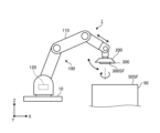
- FIG. 1 is a diagram showing an example of the external configuration of a droplet ejection system according to an embodiment.
- the droplet discharge system 1 includes a robot arm (an example of a robot part) 100, a control unit 120, a circulation device 200, and a droplet discharge head 300.
- the robot arm 100 is assembled to a base 10 that is placed on a horizontal floor surface indoors or outdoors, for example.
- Robot arm 100 has an arm section 110.
- the arm portion 110 is composed of a plurality of parts assembled so as to be bendable, straightenable, and rotatable.
- the arm section 110 can operate the droplet ejection head 300 (and the circulation device 200) mounted at the tip of the arm section 110 according to commands from the control unit 120.
- the arm section 110 can move the droplet ejection head 300 (and the circulation device 200) mounted at the tip of the arm section 110 in accordance with a command from the control unit 120.
- the arm section 110 can change the position of the droplet ejection head 300 (and the circulation device 200).
- the arm section 110 can rotate the droplet ejection head 300 (and the circulation device 200) around a predetermined rotation axis (for example, the Y axis or the Z axis) in accordance with a command from the control unit 120. Thereby, the arm section 110 can change the orientation, angle, and other postures of the droplet ejection head 300 (and the circulation device 200). Further, for example, the arm section 110 can perform various operations including swinging, tilting, and reversing of the droplet ejection head 300 (and the circulation device 200) in accordance with commands from the control unit 120.
- the arm section 110 illustrated in FIG. 1 is not particularly limited to the configuration illustrated in FIG. 1 as long as it has a degree of freedom that allows the position and posture of the droplet ejection head 300 to be changed.
- the control unit 120 is built into the robot arm 100 (arm part 110), for example. Note that the control unit 120 may be mounted on an external device independent from the robot arm 100 and connected to the robot arm 100 in a communicable manner.
- the control unit 120 controls the operation of the arm section 110 by outputting a command for controlling the operation of the arm section 110 to an actuator or the like that drives the arm section 110.
- the control unit 120 includes a control device 121 (see FIG. 6) such as a processor, and a storage device 122 (see FIG. 6) such as a memory.
- the storage device 122 includes, for example, a first control program 131 (see FIG.
- the control device 121 controls the operation of the robot arm 100 (arm section 110) based on programs, data, etc. stored in the storage device 122.
- the robot arm 100 moves the circulation device 200 and the droplet discharge head 300 mounted at the tip of the arm part 110 along a predetermined vertical axis (Z-axis) using the arm part 110, thereby moving the droplet discharge head 300.
- the position in the vertical direction (Z-axis direction) can be changed.
- the circulation device 200 and the droplet discharge head 300 for example, as shown in FIG. You can take a posture.
- the robot arm 100 can rotate, for example, the circulation device 200 and the droplet ejection head 300 assembled at the tip of the arm section 110 around a predetermined rotation axis by the arm section 110.
- the circulation device 200 and the droplet ejection head 300 can, for example, switch the longitudinal position and the lateral position, or reverse the vertical position.
- the circulation device 200 is installed at the tip of the arm section 110 of the robot arm 100.
- the circulation device 200 supplies the liquid to the droplet ejection head 300 while controlling the circulation pressure of the liquid circulating between the droplet ejection head 300 and the liquid.
- the droplet discharge head 300 is assembled to a circulation device 200 installed at the tip of the arm section 110 of the robot arm 100.
- the droplet ejection head 300 functions as a droplet ejection unit that ejects liquid to the object 50.
- the circulation pressure of the liquid supplied to the droplet ejection head 300 is affected by the operation of the droplet ejection head 300 by the robot arm 100.
- the circulation pressure (pressure) of the liquid inside the droplet discharge head 300 changes, for example, as shown in FIG. ,Change.
- FIG. 2 is a diagram illustrating changes in liquid pressure inside the droplet ejection head according to the embodiment. If the circulating pressure (pressure) of the liquid inside the droplet ejection head 300 changes, the liquid may not be ejected stably from the droplet ejection head 300.
- the present application proposes a droplet ejection system 1 that can flexibly respond to changes in the position of the droplet ejection head 300 and maintain appropriate circulation pressure of the liquid to be ejected.
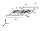
- FIG. 3 is a perspective view schematically showing the external configuration of the droplet ejection head according to the embodiment.
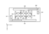
- FIG. 4 is a plan view of the droplet ejection head according to the embodiment.
- FIG. 5 is a diagram schematically showing a flow path inside the droplet ejection head according to the embodiment.
- the droplet ejection head 300 includes a housing including a box-shaped member 310 and a substantially flat plate-shaped member 320.
- the casing of the droplet ejection head 300 includes a first channel RT1 for supplying liquid from the circulation device 200 to the inside of the head, and a second channel RT1 for sending the liquid collected inside the head back to the circulation device 200.
- a flow path RT2 is installed.
- the member 320 of the droplet ejection head 300 has a supply port 321 through which liquid is supplied into the head through a first flow path RT1 , and a supply port 321 through which liquid is supplied into the head through a second flow path RT2 . It has a recovery port 322 through which liquid is recovered from inside.
- the droplet ejection head 300 includes a supply reservoir 301, a supply manifold 302, a recovery manifold 303, a recovery reservoir 304, and an element 305.
- the supply reservoir 301 has an elongated shape extending in the longitudinal direction (Y-axis direction) of the droplet ejection head 300 and is connected to the supply manifold 302 .
- Supply reservoir 301 has a flow path inside. As shown in FIG. 4 or 5, the liquid is supplied to the supply reservoir 301 through the first channel RT 1 and the supply port 321, and the liquid stored in the channel of the supply reservoir 301 is sent out to the supply manifold 302. .
- the supply manifold 302 has an elongated shape extending in the lateral direction (X-axis direction) of the droplet ejection head 300 to the front of the collection reservoir 304.
- the supply manifold 302 has a flow path therein that communicates with the flow path of the supply reservoir 301 and the element 305 . As shown in FIG. 4 or 5, liquid pumped from supply reservoir 301 to supply manifold 302 is pumped from supply manifold 302 to element 305.
- the recovery manifold 303 has an elongated shape that extends in the lateral direction (X-axis direction) of the droplet ejection head 300 to the front of the supply reservoir 301.
- the recovery manifold 303 has a channel therein that communicates with the channel included in the recovery reservoir 304 and the element 305 . As shown in FIG. 4 or 5, the liquid that is not discharged to the outside from the element 305 (discharge hole 305h) is sent to the recovery manifold 303.
- the collection reservoir 304 has an elongated shape extending in the longitudinal direction (Y-axis direction) of the droplet ejection head 300 and is connected to the collection manifold 303 .
- Recovery reservoir 304 has a flow path inside. As shown in FIG. 4 or 5, the liquid sent from the recovery manifold 303 to the recovery reservoir 304 and stored in the channel of the recovery reservoir 304 is passed through the recovery port 322 and the second channel RT 2 to the circulation device 200. sent back to.
- the element 305 has a discharge hole 305h.
- the element 305 sucks liquid from the supply manifold 302 using negative pressure generated in a pressure chamber (not shown), and directs the sucked liquid toward the object 50 from the discharge hole 305h using positive pressure generated in a pressure chamber (not shown). Dispense.
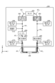
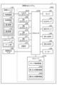
- FIG. 6 is a block diagram showing an example of the functional configuration of the droplet ejection system according to the embodiment.
- FIG. 7 is a diagram schematically showing the circulation mechanism of the circulation device in the droplet discharge system according to the embodiment.
- FIG. 6 shows an example of the functional configuration of the droplet discharge system 1 according to the embodiment, and as long as the configuration can realize various functions of the droplet discharge system 1 according to the embodiment, the configuration shown in FIG. There is no need to be particularly limited to the examples.
- FIG. 6 shows the components included in the droplet ejection system 1 according to the embodiment as functional blocks, and the description of other general components is omitted.
- each component of the droplet ejection system 1 shown in FIG. 6 is functionally conceptual, and is not limited to the example shown in FIG. 6, and may not necessarily be physically configured as shown. Not needed.
- the specific form of distribution/integration of each functional block is not limited to what is shown in the diagram, and all or part of it can be functionally or physically distributed in arbitrary units depending on various loads, usage conditions, etc. - Can be configured in an integrated manner.
- the droplet discharge system 1 includes a circulation device 200.
- the circulation device 200 includes a tank 201, a discharge pump 202, a suction pump 203, a first proportional valve 204, a second proportional valve 205, and a heater 206.
- the circulation device 200 also includes an input/output interface 207, a first pressure sensor 208, a second pressure sensor 209, a third pressure sensor 210, a fourth pressure sensor 211, and a flow meter 212.
- the circulation device 200 also includes a storage 214 and a processor 215. Note that the storage 214 and the processor 215 may be installed independently of the circulation device 200.
- the droplet ejection system 1 also includes a robot arm 100, a control unit 120, and a droplet ejection head 300.
- the circulation device 200 includes a first flow path RT1 and a second flow path RT2 .
- the first channel RT 1 is a channel that communicates between the tank 201 and the droplet discharge head 300 and allows the liquid stored in the tank 201 to flow into the droplet discharge head 300 .
- the second flow path RT 2 is a flow path that communicates between the tank 201 and the droplet ejection head 300 and allows the liquid that has flowed into the droplet ejection head 300 to flow back to the tank 201 .
- the liquid collected within the droplet ejection head 300 without being ejected to the outside from the droplet ejection head 300 is sent back to the tank 201 through the second channel RT 2 .
- the first flow path RT 1 and the second flow path RT 2 can be implemented, for example, by piping formed of a predetermined material that does not interact with liquid components.
- the processor 215 of the circulation device 200 having such various parts controls the circulation pressure of the liquid circulating clockwise between the tank 201 and the droplet ejection head 300, for example, as shown in FIG.
- the tank 201 stores liquid to be supplied to the droplet ejection head 300.
- the tank 201 functions as a storage section that stores liquid to be supplied to the droplet ejection head 300.
- the discharge pump 202 supplies the liquid stored in the tank 201 to the droplet discharge head 300 through the first channel RT1 .
- the discharge pump 202 generates positive pressure for discharging the liquid stored in the tank 201 to the droplet discharge head 300.
- the discharge pump 202 can, for example, deliver the liquid stored in the tank 201 to the droplet discharge head 300 at a preset constant supply pressure.
- the suction pump 203 supplies the liquid collected in the droplet ejection head 300 to the tank 201 through the second flow path RT2 .
- the suction pump 203 generates negative pressure to suck the liquid collected by the droplet discharge head 300 and send it back to the tank 201 .
- the suction pump 203 can send the liquid sucked from the droplet ejection head 300 to the tank 201, for example, at a preset constant recovery pressure.
- the discharge pump 202 and the suction pump 203 can be implemented by a rotary pump such as a gear pump or a positive displacement pump such as a diaphragm pump.
- the first proportional valve 204 is inserted into the first flow path RT1 between the tank 201 and the droplet discharge head 300, and is a first valve that proportionally controls the flow rate of the liquid supplied to the droplet discharge head 300. function as a department.
- the first proportional valve 204 can continuously change the cross-sectional area of the liquid flow path between 0 and 100%, and controls the flow rate of the liquid to a desired flow rate.
- the first proportional valve 204 can reduce the supply pressure when supplying the liquid to the droplet ejection head 300 by reducing the cross-sectional area of the liquid flow path.
- the first proportional valve 204 can increase the supply pressure when supplying the liquid to the droplet ejection head 300 by increasing the cross-sectional area of the liquid flow path.
- the second proportional valve 205 is inserted into the second flow path RT 2 between the tank 201 and the droplet discharge head 300, and proportionally controls the flow rate of the liquid supplied from the droplet discharge head 300 to the tank 201. It functions as a second valve part.
- the second proportional valve 205 like the first proportional valve 204, can continuously change the cross-sectional area of the liquid flow path between 0 and 100%, and controls the flow rate of the liquid to a desired flow rate.
- the second proportional valve 205 can reduce the recovery pressure when recovering the liquid from the droplet ejection head 300 by reducing the cross-sectional area of the liquid flow path.
- the second proportional valve 205 can increase the recovery pressure when recovering the liquid from the droplet ejection head 300 by increasing the cross-sectional area of the liquid flow path.
- the first proportional valve 204 and the second proportional valve 205 can be implemented by an electromagnetic proportional switching valve or a pneumatic proportional switching valve.
- the heater 206 is provided in the first flow path RT 1 or adjacent to the first flow path RT 1 and heats the liquid flowing through the first flow path RT 1 .
- the input/output interface 207 exchanges various information with the control unit 120 of the robot arm 100.
- the input/output interface 207 can receive, for example, a signal instructing to start ejecting the liquid and a signal instructing the end of ejecting the liquid from the control unit 120. Further, the input/output interface 207 can obtain information regarding the operation of the droplet ejection head 300 from the first control program 131 stored in the storage device 122 of the control unit 120 under the control of the processor 215. As the information regarding the operation of the droplet discharge head 300, for example, numerical values regarding the movement of the droplet discharge head 300 are acquired.
- Numerical values related to the movement of the droplet discharge head 300 include, for example, the position of the droplet discharge head 300 in the vertical direction, the acceleration in the vertical direction acting on the droplet discharge head 300, and the horizontal direction acting on the droplet discharge head 300. Examples include acceleration.
- the information regarding the operation of the droplet ejection head 300 may be, for example, numerical values regarding various operations including rocking, tilting, reversing, etc. of the droplet ejection head 300.
- the input/output interface 207 functions as an acquisition unit that acquires information regarding the operation of the droplet discharge head 300 from the first control program 131 that controls the operation of the robot arm 100 that operates the droplet discharge head 300.
- the first pressure sensor 208 measures the pressure of the liquid delivered from the tank 201 to the droplet ejection head 300 by the ejection pump 202.
- the first pressure sensor 208 measures the pressure downstream of the discharge pump 202 in the direction of liquid circulation in the circulation device 200 .
- First pressure sensor 208 sends measurement results to processor 215 .
- the second pressure sensor 209 measures the pressure of the liquid sucked from the droplet discharge head 300 by the suction pump 203 and fed to the tank 201.
- the second pressure sensor 209 measures the pressure upstream of the suction pump 203 in the direction of liquid circulation in the circulation device 200 .
- Second pressure sensor 209 sends measurement results to processor 215 .
- the third pressure sensor 210 functions as a first pressure measurement unit that measures the pressure of the liquid flowing between the first proportional valve 204 and the droplet ejection head 300 as a supply pressure through the first flow path RT1 . .
- the third pressure sensor 210 measures the pressure of the liquid just before it passes through the first proportional valve 204 and flows into the droplet ejection head 300 . That is, the third pressure sensor 210 measures the pressure downstream of the first proportional valve 204 in the circulation direction of the liquid in the circulation device 200 as the supply pressure.
- Third pressure sensor 210 sends measurement results to processor 215 .
- the fourth pressure sensor 211 functions as a second pressure measurement unit that measures the pressure of the liquid flowing between the second proportional valve 205 and the droplet discharge head 300 as a recovery pressure through the second flow path RT 2 . .
- the fourth pressure sensor 211 measures the pressure of the liquid immediately after it is sent out from the droplet ejection head 300 toward the tank 201 and before passing through the second proportional valve 205 . That is, the fourth pressure sensor 211 measures the pressure upstream of the second proportional valve 205 in the circulation direction of the liquid in the circulation device 200 as the recovery pressure. Fourth pressure sensor 211 sends measurement results to processor 215 .
- the flow meter 212 measures the flow rate of the liquid supplied to the droplet ejection head 300. Flow meter 212 sends measurement results to processor 215 .
- the storage 214 stores programs and data necessary for various processes of the droplet ejection system 1 (here, the circulation device 200).
- the storage 214 stores, for example, pump control information 241 and pressure adjustment information 242.
- the pump control information 241 is data for pump control that is set in advance.
- the data for pump control includes, for example, the target value of the pressure (positive pressure) applied to the liquid when the discharge pump 202 pumps out the liquid, and the pressure (negative pressure) applied to the liquid when the suction pump 203 sucks the liquid.
- the positive pressure of the ejection pump 202 is, for example, about 1.2 to 3 times higher than the pressure when liquid is supplied to the droplet ejection head 300.
- a value is set in advance as a target value.
- the negative pressure of the suction pump 203 is set in advance to a value approximately 1.2 to 3 times lower than the pressure at which liquid is supplied to the droplet ejection head 300 as a target value.
- the pressure adjustment information 242 includes adjustment values for each of the supply pressure and recovery pressure for suppressing changes in liquid pressure inside the droplet discharge head 300 for each numerical value related to the movement of the droplet discharge head 300. This is the associated data.
- FIG. 8 is a diagram showing an overview of pressure adjustment information according to the embodiment.
- the pressure adjustment information 242 includes an item of "numerical value related to head movement", an item of “adjustment value (supply pressure)", and an item of “adjustment value (recovery pressure)", and these items are are correlated with each other.
- the item “Numerical values related to head movement” includes the vertical position of the droplet ejection head 300, the vertical acceleration acting on the droplet ejection head 300, or the value related to the movement of the droplet ejection head 300.
- the horizontal acceleration acting on the head 300 is stored.
- a target value for adjusting the supply pressure hereinafter also referred to as “adjustment value” as appropriate
- a target value hereinafter also referred to as "adjustment value” as appropriate
- the pressure adjustment information 242 may be prepared depending on the type of numerical value related to the movement of the droplet ejection head 300. That is, the pressure adjustment information 242 is individually set for each of the vertical position of the droplet ejection head 300, the vertical acceleration acting on the droplet ejection head 300, and the horizontal acceleration acting on the droplet ejection head 300. May be provided.
- the processor 215 executes various processes in the droplet ejection system 1 (here, the circulation device 200) based on programs, data, etc. stored in the storage 214.
- the processor 215 realizes various functions for controlling each part of the droplet ejection system 1 (here, the circulation device 200) by reading and executing a computer program stored in the storage 214.
- the processor 215 Based on the measurement result of the first pressure sensor 208 and the measurement result of the third pressure sensor 210, the processor 215 adjusts the positive pressure applied to the liquid when the discharge pump 202 pumps out the liquid so as to keep it constant. For example, the processor 215 maintains the liquid pressure obtained from the measurement result of the first pressure sensor 208 at a pressure approximately 1.2 to 3 times greater than the liquid pressure obtained from the measurement result of the third pressure sensor 210. Then, adjust the positive pressure of the discharge pump 202.
- the processor 215 adjusts the negative pressure applied to the liquid when the suction pump 203 sucks the liquid so as to keep it constant. For example, the processor 215 maintains the liquid pressure obtained from the measurement result of the second pressure sensor 209 to be about 1.2 to 3 times lower than the liquid pressure obtained from the measurement result of the fourth pressure sensor 211. Then, adjust the negative pressure of the suction pump 203.
- the processor 215 controls the tank 201 and the droplet ejection head by adjusting the pressure difference between the positive pressure applied to the liquid by the ejection pump 202 and the negative pressure applied to the liquid by the suction pump 203 to be constant. 300.
- the processor 215 controls the first proportional valve 204 and the second proportional valve 205 based on the values obtained by the input/output interface 207, and adjusts the supply pressure and the recovery pressure. A method of controlling the first proportional valve 204 and the second proportional valve 205 will be described below with reference to FIGS. 9 to 11.
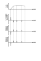
- FIG. 9 is a diagram for explaining a method of controlling the first proportional valve and the second proportional valve based on the position of the droplet ejection head according to the embodiment.
- the first row from the top of FIG. 9 schematically shows an example of the relationship between the position of the droplet ejection head 300 in the vertical direction and time.
- an example of the relationship between each adjustment value of the supply pressure and the recovery pressure and time is schematically shown.
- an example of the relationship between the circulation pressure of the liquid inside the droplet ejection head 300 and time is schematically shown.
- the attitude of the droplet ejection head 300 is such that the liquid ejection surface 300SF is directed vertically downward (see FIG. 1).
- the processor 215 controls the input/output interface 207 to obtain the position of the droplet ejection head 300 in the vertical direction. Specifically, the input/output interface 207 obtains the position of the droplet ejection head 300 in the vertical direction from the first control program 131 as a numerical value related to the movement of the droplet ejection head 300 .
- the processor 215 adjusts the supply pressure and the recovery pressure so that the circulating pressure (pressure) of the liquid inside the droplet ejection head 300, which changes depending on the acquired position of the droplet ejection head 300, remains constant.
- the circulation pressure (pressure) of the liquid is constant is a concept that includes not only the case where the pressure of the liquid is strictly constant but also the case where the pressure of the liquid approaches constant. That is, the processor 215 may adjust the supply pressure and the recovery pressure so that the circulation pressure (pressure) of the liquid inside the droplet ejection head 300 approaches a constant value.
- the processor 215 may adjust the supply pressure and withdrawal pressure so that the circulating pressure decreases if the pressure in the head increases, and adjusts the supply pressure and withdrawal pressure such that the circulating pressure increases if the pressure in the head decreases.
- the supply pressure and withdrawal pressure may be adjusted.
- the circulation pressure (pressure) of the liquid inside the droplet discharge head 300 decreases due to the influence of the water head pressure.
- the processor 215 refers to the pressure adjustment information 242 and identifies adjustment values for each of the supply pressure and recovery pressure that correspond to the acquired position of the droplet ejection head 300. The adjustment values of each of the supply pressure and recovery pressure increase as the position of the droplet ejection head 300 becomes higher.
- the processor 215 expands the flow passage cross-sectional area of the first proportional valve 204 in order to increase the supply pressure to the target pressure based on the specified adjustment value. , increases the flow rate of fluid passing through the first proportional valve 204.
- the processor 215 expands the cross-sectional area of the flow path of the second proportional valve 205 in order to increase the recovery pressure to the target pressure based on the specified adjustment value while referring to the measurement result of the fourth pressure sensor 211. , increases the flow rate of fluid passing through the second proportional valve 205.
- the processor 215 refers to the pressure adjustment information 242 and identifies adjustment values for each of the supply pressure and recovery pressure that correspond to the acquired position of the droplet ejection head 300. The adjustment values of each of the supply pressure and recovery pressure decrease as the position of the droplet ejection head 300 becomes lower.
- the processor 215 narrows the flow passage cross-sectional area of the first proportional valve 204 in order to reduce the supply pressure to the target pressure based on the specified adjustment value. , reducing the flow rate of fluid passing through the first proportional valve 204 .
- the processor 215 refers to the measurement result of the fourth pressure sensor 211 and narrows the flow path cross-sectional area of the second proportional valve 205 in order to reduce the recovery pressure to the target pressure based on the specified adjustment value. , reducing the flow rate of fluid passing through the second proportional valve 205.
- the processor 215 can increase or decrease the flow rate of the fluid passing through the first proportional valve 204 and the second proportional valve 205, depending on the position of the droplet ejection head 300 in the vertical direction. Thereby, the processor 215 can keep the circulating pressure (pressure) of the liquid inside the droplet ejection head 300 constant.
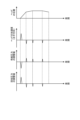
- FIG. 10 is a diagram for explaining a method of controlling the first proportional valve and the second proportional valve based on the vertical acceleration acting on the droplet ejection head according to the embodiment.
- the first row from the top of FIG. 10 schematically shows an example of the relationship between the position of the droplet ejection head 300 in the vertical direction and time.
- an example of the relationship between the vertical acceleration acting on the droplet ejection head 300 and time is schematically shown.
- the third and fourth rows from the top of FIG. 10 an example of the relationship between each adjustment value of the supply pressure and the recovery pressure and time is schematically shown.
- the attitude of the droplet ejection head 300 is such that the liquid ejection surface 300SF is directed vertically downward (see FIG. 1).
- the inside of the droplet discharge head 300 is affected by the water head pressure acting on the liquid circulating inside the head. It is expected that the circulating pressure (pressure) of the liquid at the If the circulating pressure (pressure) of the liquid inside the droplet ejection head 300 changes, the liquid may not be ejected stably from the droplet ejection head 300.
- the processor 215 controls the input/output interface 207 to obtain the vertical acceleration acting on the droplet ejection head 300.
- the input/output interface 207 obtains the vertical acceleration acting on the droplet ejection head 300 from the first control program 131 as a numerical value related to the movement of the droplet ejection head 300 .
- the processor 215 adjusts the supply pressure and the recovery pressure so that the circulation pressure (pressure) of the liquid inside the droplet ejection head 300, which changes according to the acquired vertical acceleration, remains constant.
- the circulation pressure (pressure) of the liquid inside the droplet ejection head 300 increases due to the influence of the water head pressure. Ru.
- the processor 215 refers to the pressure adjustment information 242 and identifies adjustment values for each of the supply pressure and recovery pressure that correspond to the acquired vertical acceleration. The adjustment values of each of the supply pressure and the recovery pressure decrease as the vertical upward acceleration of the droplet ejection head 300 increases.
- the processor 215 narrows the flow passage cross-sectional area of the first proportional valve 204 in order to reduce the supply pressure to the target pressure based on the specified adjustment value. , reducing the flow rate of fluid passing through the first proportional valve 204 .
- the processor 215 refers to the measurement result of the fourth pressure sensor 211 and narrows the flow path cross-sectional area of the second proportional valve 205 in order to reduce the recovery pressure to the target pressure based on the specified adjustment value. , reducing the flow rate of fluid passing through the second proportional valve 205.
- the circulation pressure (pressure) of the liquid inside the droplet discharge head 300 decreases due to the influence of the water head pressure. is expected.
- the processor 215 refers to the pressure adjustment information 242 and identifies adjustment values for each of the supply pressure and recovery pressure that correspond to the acquired position of the droplet ejection head 300. The adjustment values of each of the supply pressure and the recovery pressure increase as the vertical upward acceleration of the droplet ejection head 300 decreases.
- the processor 215 expands the flow passage cross-sectional area of the first proportional valve 204 in order to increase the supply pressure to the target pressure based on the specified adjustment value. , increases the flow rate of fluid passing through the first proportional valve 204.
- the processor 215 expands the cross-sectional area of the flow path of the second proportional valve 205 in order to increase the recovery pressure to the target pressure based on the specified adjustment value while referring to the measurement result of the fourth pressure sensor 211. , increases the flow rate of fluid passing through the second proportional valve 205.
- the processor 215 can increase or decrease the flow rate of the fluid passing through the first proportional valve 204 and the second proportional valve 205 in accordance with the vertical acceleration acting on the droplet ejection head 300. Thereby, the processor 215 can keep the circulating pressure (pressure) of the liquid inside the droplet ejection head 300 constant.
- FIG. 11 is a diagram for explaining a method of controlling the first proportional valve and the second proportional valve based on the horizontal acceleration acting on the droplet ejection head according to the embodiment.
- the first row from the top of FIG. 11 schematically shows an example of the relationship between the horizontal position of the droplet ejection head 300 and time.
- an example of the relationship between horizontal acceleration acting on the droplet ejection head 300 and time is schematically shown.
- an example of the relationship between each adjustment value of the supply pressure and the recovery pressure and time is schematically shown.
- the attitude of the droplet ejection head 300 is such that the liquid ejection surface 300SF is directed vertically downward (see FIG. 1).
- the horizontal acceleration acting on the droplet ejection head 300 is the acceleration of the liquid flowing inside the droplet ejection head 300 in a direction from the downstream side to the upstream side.
- the downstream side refers to the recovery side where liquid is recovered from the droplet ejection head 300 (that is, the recovery port 322 side)
- the upstream side refers to the recovery side where the liquid is supplied to the droplet ejection head 300.
- This is the supply side (that is, the supply port 321 side).
- the inside of the droplet discharge head 300 is affected by the head pressure acting on the liquid circulating inside the head. It is expected that the circulating pressure (pressure) of the liquid at the If the circulating pressure (pressure) of the liquid inside the droplet ejection head 300 changes, the liquid may not be ejected stably from the droplet ejection head 300.
- the processor 215 controls the input/output interface 207 to obtain the horizontal acceleration acting on the droplet ejection head 300.
- the input/output interface 207 obtains the horizontal acceleration acting on the droplet ejection head 300 from the first control program 131 as a numerical value related to the movement of the droplet ejection head 300 .
- the processor 215 adjusts the supply pressure and the recovery pressure so that the circulation pressure (pressure) of the liquid inside the droplet ejection head 300, which changes according to the acquired horizontal acceleration, remains constant.
- the processor 215 refers to the pressure adjustment information 242 to identify adjustment values for each of the supply pressure and the recovery pressure that correspond to the acquired horizontal acceleration.
- the adjustment value of the supply pressure decreases as the acceleration of the liquid flowing inside the droplet ejection head 300 in the direction from the downstream side to the upstream side increases.
- the adjustment value of the recovery pressure increases as the acceleration of the liquid flowing inside the droplet ejection head 300 in the direction from the downstream side to the upstream side increases.
- the processor 215 narrows the flow passage cross-sectional area of the first proportional valve 204 in order to reduce the supply pressure to the target pressure based on the specified adjustment value. , reducing the flow rate of fluid passing through the first proportional valve 204 .
- the processor 215 expands the cross-sectional area of the flow path of the second proportional valve 205 in order to increase the recovery pressure to the target pressure based on the specified adjustment value while referring to the measurement result of the fourth pressure sensor 211. , increases the flow rate of fluid passing through the second proportional valve 205.
- the processor 215 refers to the pressure adjustment information 242 to identify adjustment values for each of the supply pressure and the recovery pressure that correspond to the acquired horizontal acceleration.
- the adjustment value of the supply pressure increases as the acceleration of the liquid flowing inside the droplet ejection head 300 in the direction from the downstream side to the upstream side becomes smaller.
- the adjustment value of the recovery pressure decreases as the acceleration of the liquid flowing inside the droplet discharge head 300 in the direction from the downstream side to the upstream side decreases.
- the processor 215 expands the flow passage cross-sectional area of the first proportional valve 204 in order to increase the supply pressure to the target pressure based on the specified adjustment value. , increases the flow rate of fluid passing through the first proportional valve 204.
- the processor 215 refers to the measurement result of the fourth pressure sensor 211 and narrows the flow path cross-sectional area of the second proportional valve 205 in order to reduce the recovery pressure to the target pressure based on the specified adjustment value. , reducing the flow rate of fluid passing through the second proportional valve 205.
- the processor 215 can increase or decrease the flow rate of the fluid passing through the first proportional valve 204 and the second proportional valve 205 in accordance with the horizontal acceleration acting on the droplet ejection head 300. Thereby, the processor 215 can keep the circulating pressure (pressure) of the liquid inside the droplet ejection head 300 constant.
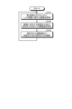
- FIG. 12 is a flowchart illustrating an example of the processing procedure of the droplet ejection system according to the embodiment.
- the processing shown in FIG. 12 is executed by the processor 215.
- the process shown in FIG. 12 is repeatedly executed while the droplet ejection system 1 is in operation.
- the processor 215 controls the input/output interface 207 to obtain numerical values regarding the movement of the droplet ejection head 300 from the first control program 131 (step S101). That is, the input/output interface 207 uses at least the following values: the vertical position of the droplet ejection head 300, the vertical acceleration acting on the droplet ejection head 300, and the horizontal acceleration acting on the droplet ejection head 300. Get one.
- the processor 215 refers to the pressure adjustment information 242 and identifies adjustment values for each of the supply pressure and recovery pressure that correspond to the acquired numerical values (step S102).
- the processor 215 adjusts the supply pressure and recovery pressure of the liquid circulating between the tank 201 and the droplet ejection head 300 to the specified adjustment value (step S103), and returns to the processing procedure of step S101.
- FIG. 13 is a block diagram showing an example of the functional configuration of a droplet ejection system according to another embodiment. Note that the circulation mechanism of the circulation device 200A in the droplet discharge system 1 according to another embodiment is similar to the circulation mechanism of the circulation device 200 in the droplet discharge system 1 according to the embodiment shown in FIG. omitted.
- a droplet discharge system 1 includes a circulation device 200A.
- the circulation device 200A includes an input/output interface 207A instead of the input/output interface 207 shown in FIG.
- the circulation device 200A includes a storage 214A and a processor 215A instead of the storage 214 and processor 215 shown in FIG.
- the input/output interface 207A exchanges various information with the control unit 120 of the robot arm 100. Like the input/output interface 207, the input/output interface 207A obtains numerical values regarding the movement of the droplet ejection head 300 from the first control program 131 stored in the storage device 122 of the control unit 120 under the control of the processor 215. can do. The input/output interface 207A can further acquire the printing rate of the droplet ejection head 300 from the second control program 132 stored in the storage device 122 of the control unit 120 under the control of the processor 215A.
- This "printing rate” refers to the ratio (S1/S2) of the cumulative area S1 of the liquid ejected onto the object 50 to the area S2 of the spray surface 50SF of the object 50 (S1/S2), and is calculated from the image data to be printed. can be done.
- the input/output interface 207A functions as an acquisition unit that acquires the printing rate of the droplet discharge head 300 from the second control program 132 that controls operations related to discharge of the droplet discharge head 300.
- the storage 214A stores programs and data necessary for various processes of the droplet ejection system 1 (here, the circulation device 200A).
- the storage 214A stores, for example, pump control information 241, first pressure adjustment information 242A, and second pressure adjustment information 243A.
- the pump control information 241 has the same data structure as the pump control information 241 shown in FIG.
- the first pressure adjustment information 242A has the same data structure as the pressure adjustment information 242 shown in FIG. 6.
- the second pressure adjustment information 243A includes adjustment values for each of the supply pressure and recovery pressure for suppressing changes in liquid pressure inside the droplet discharge head 300 for each print rate of the droplet discharge head 300. This is data that corresponds to FIG. 14 is a diagram showing an overview of second pressure adjustment information according to another embodiment.
- the second pressure adjustment information 243A includes an item of "printing rate”, an item of "adjustment value (supply pressure)", and an item of “adjustment value (recovery pressure)", and these items are are correlated with each other.
- the “printing rate” item stores the printing rate of the droplet ejection head 300.
- a target value for adjusting the supply pressure hereinafter also referred to as “adjustment value” as appropriate
- a target value hereinafter also referred to as “adjustment value” as appropriate
- the circulation pressure (pressure) of the liquid circulating inside the head changes, and the liquid may not be ejected stably from the droplet ejection head 300. . Therefore, through experiments, simulations, etc., the relationship between the respective adjustment values of the supply pressure and the recovery pressure is determined in advance so that the pressure of the liquid inside the head remains constant with respect to changes in the printing rate of the droplet ejection head 300.
- the supply pressure is obtained from the measurement result by the third pressure sensor 210.
- the recovery pressure is obtained from the measurement result by the fourth pressure sensor 211. Then, each adjustment value of the supply pressure and the recovery pressure is associated with each print rate of the droplet ejection head 300 and stored in the second pressure adjustment information 243A.
- the processor 215A controls the first proportional valve 204 and the second proportional valve 205 based on the numerical values obtained by the input/output interface 207A, and adjusts the supply pressure and the recovery pressure. In addition, in parallel with adjusting the supply pressure and recovery pressure based on these values, the processor 215A controls the first proportional valve 204 and the second proportional valve 205 based on the printing rate acquired by the input/output interface 207A. and adjust the supply pressure and recovery pressure. That is, the processor 215A adjusts the supply pressure and recovery pressure based on numerical values related to the operation of the droplet discharge head 300, and adjusts the supply pressure and recovery pressure based on the printing rate of the droplet discharge head 300 in parallel.
- a method of controlling the first proportional valve 204 and the second proportional valve 205 based on the printing rate of the droplet ejection head 300 will be described.
- the head pressure acts on the liquid circulating inside the head, so that the circulation pressure of the liquid inside the droplet discharge head 300 ( pressure) is expected to change. Furthermore, when the printing rate of the droplet ejection head 300 changes, it is expected that the circulation pressure (pressure) of the liquid inside the droplet ejection head 300 will also change. If the circulating pressure (pressure) of the liquid inside the droplet ejection head 300 changes, the liquid may not be ejected stably from the droplet ejection head 300.
- the processor 215A controls the input/output interface 207 to obtain numerical values regarding the movement of the droplet ejection head 300. Specifically, the input/output interface 207 acquires the position of the droplet ejection head 300 in the vertical direction, etc. from the first control program 131 as numerical values related to the movement of the droplet ejection head 300. Furthermore, the processor 215A controls the input/output interface 207A to obtain the printing rate of the droplet ejection head 300. Specifically, the input/output interface 207A obtains the printing rate of the droplet ejection head 300 from the second control program 132.
- the processor 215A adjusts the supply pressure and recovery pressure so that the circulation pressure (pressure) of the liquid inside the droplet ejection head 300, which changes depending on the acquired position of the droplet ejection head 300, remains constant.
- the method of controlling the first proportional valve 204 and the second proportional valve 205 based on the position of the droplet ejection head 300 is similar to the control method shown in FIGS. 9 to 11.
- the processor 215A adjusts the supply pressure and the recovery pressure so that the circulating pressure (pressure) of the liquid inside the droplet ejection head 300, which changes according to the obtained printing rate of the droplet ejection head 300, is constant. adjust.
- the processor 215A refers to the second pressure adjustment information 243A and specifies adjustment values for each of the supply pressure and the recovery pressure that correspond to the obtained printing rate of the droplet ejection head 300. The adjustment values of each of the supply pressure and recovery pressure increase as the printing rate of the droplet ejection head 300 increases.
- the processor 215A expands the flow passage cross-sectional area of the first proportional valve 204 in order to increase the supply pressure to the target pressure based on the specified adjustment value. , increases the flow rate of fluid passing through the first proportional valve 204.
- the processor 215A refers to the measurement result of the fourth pressure sensor 211 and expands the flow passage cross-sectional area of the second proportional valve 205 in order to increase the recovery pressure to the target pressure based on the specified adjustment value. , increases the flow rate of fluid passing through the second proportional valve 205.
- the processor 215A can increase or decrease the flow rate of the fluid passing through the first proportional valve 204 and the second proportional valve 205, depending on the printing rate of the droplet ejection head 300. Thereby, the processor 215A can keep the circulating pressure (pressure) of the liquid inside the droplet ejection head 300 constant.
- FIG. 15 is a flowchart illustrating an example of a processing procedure of a droplet ejection system according to another embodiment.
- the processing shown in FIG. 15 is executed by the processor 215A.
- the process shown in FIG. 15 is repeatedly executed while the droplet ejection system 1 is in operation.
- the processor 215A controls the input/output interface 207A to obtain numerical values regarding the movement of the droplet ejection head 300 from the first control program 131 (step S201). That is, the input/output interface 207A uses at least the following values: the vertical position of the droplet ejection head 300, the vertical acceleration acting on the droplet ejection head 300, and the horizontal acceleration acting on the droplet ejection head 300. Get one.
- the processor 215A controls the input/output interface 207A to obtain the printing rate of the droplet ejection head 300 from the second control program 132 (step S202).
- the processor 215A refers to the first pressure adjustment information 242A and specifies adjustment values for each of the supply pressure and recovery pressure that correspond to the acquired numerical values (step S203).
- the processor 215A adjusts the supply pressure and recovery pressure of the liquid circulating between the tank 201 and the droplet ejection head 300 to the specified adjustment value (step S204), and returns to the processing procedure of step S201.
- the processor 215A performs the processing steps S205 to S206 based on the printing rate of the droplet ejection head 300, overlapping the processing steps S203 to S204 based on numerical values regarding the operation of the droplet ejection head 300.
- the processor 215A refers to the second pressure adjustment information 243A and specifies adjustment values for each of the supply pressure and the recovery pressure that correspond to the obtained print rate of the droplet ejection head 300 (step S205).
- the processor 215A adjusts the supply pressure and recovery pressure of the liquid circulating between the tank 201 and the droplet ejection head 300 to the specified adjustment value (step S206), and returns to the processing procedure of step S201.
- the processor 215A determines that a water head pressure to the extent that it affects the circulation pressure of the liquid circulating in the droplet ejection head 300 is not generated. be able to. In such a case, the processor 215A may stop adjusting the supply pressure and recovery pressure based on numerical values related to the operation of the droplet ejection head 300 (processing procedures of steps S203 to S204). That is, when the water head pressure to the extent that it affects the circulation pressure of the liquid circulating in the droplet ejection head 300 is not generated, the processor 215A adjusts the supply pressure and recovery pressure based on the printing rate of the droplet ejection head 300. Only (the processing procedure of steps S205 and S206) is performed. Thereby, the circulation pressure (pressure) of the liquid inside the droplet ejection head 300 can be kept constant while suppressing an increase in processing load.
- the droplet ejection system 1 measures the flow rate of the liquid supplied to the droplet ejection head 300 with a flowmeter 212 connected to the first flow path RT1, as shown in FIGS. 6 and 7. The measured flow rate of the liquid and the ejection amount determined from the printing rate may be compared. Then, the droplet discharge system 1 adjusts the supply pressure and recovery pressure so as not to increase or decrease the circulation pressure when the discharge amount determined from the printing rate is larger than the flow rate of the liquid measured by the flowmeter 212. It may be adjusted.
- the processor 215A determines the ejection amount expected from the printing rate. At the same time, the flow rate of the liquid measured by the flow meter 212 is also obtained. Then, the processor 215A compares the ejection amount determined from the printing rate with the liquid flow rate measured by the flow meter 212. When the discharge amount determined from the printing rate is larger than the liquid flow rate measured by the flow meter 212, the processor 215A controls the first proportional valve 204 and the second proportional valve so as not to increase the circulating pressure or to decrease the circulating pressure. 205 may be controlled.
- the amount of ejection may decrease due to non-ejection of droplets due to air bubbles or foreign matter in many channels (ejection holes 305h).
- the circulation pressure may be adjusted to increase based on the information on the printing rate even though the actual discharge amount is small (see S205 and S206 in FIG. 15).
- the printing rate here is, for example, the ratio (S1/ S2) and can be calculated from the image data to be printed. If this happens, the pressure inside the droplet ejection head 300 will become inappropriately high, which may cause problems such as ink overflowing from the ejection holes 305h.
- the expected discharge amount is calculated from the printing rate, and the expected discharge amount value is compared with the measured value of the flowmeter 212. It is better not to increase the circulation pressure or to reduce it if the measured value of
- the measured value of the flow meter 212 is the sum of the ejected amount and the circulation flow rate, so it is normal for the ejected amount estimated from the printing rate to be smaller than the measured value of the flow meter 212.
- a state in which the ejection amount determined from the above-mentioned printing rate is greater than the flow rate measured by the flow meter 212 is not normal.
- the coating apparatus (for example, droplet discharge system 1) according to the embodiment includes a storage section (for example, tank 201), a robot section (for example, robot arm 100), and a first flow path (for example, , the first flow path RT 1 ), the second flow path (for example, the second flow path RT 2 ), the acquisition unit (for example, the input/output interfaces 207, 207A), and the control unit (for example, the processor 215, 215A).
- the storage section stores liquid to be supplied to the droplet ejection section (for example, the droplet ejection head 300).
- the robot section operates as a droplet discharge section.
- the first flow path is a flow path that communicates between the storage section and the droplet discharge section and allows the liquid stored in the storage section to flow into the droplet discharge section.
- the second flow path is a flow path that communicates between the storage section and the droplet discharge section and allows the liquid that has flowed into the droplet discharge section to flow back to the storage section.
- the acquisition unit acquires information regarding the operation of the droplet discharge unit from a program (for example, the first control program 131) that controls the operation of the robot unit.
- the control section controls the circulation pressure of the liquid circulating between the storage section and the droplet discharge section.
- the control unit controls the circulating pressure based on information regarding the operation.
- the coating apparatus includes a first valve part (for example, the first proportional valve 204), a second valve part (for example, the second proportional valve 205), and a first pressure measuring part (for example, the first proportional valve 205). 3 pressure sensor 210) and a second pressure measurement section (for example, a fourth pressure sensor 211).
- the first valve part may be inserted into the first flow path and control the flow rate of the liquid fed from the storage part to the droplet discharge part.
- the second valve section may be inserted into the second flow path and control the flow rate of the liquid delivered from the droplet discharge section to the storage section.
- the first pressure measuring section may measure the pressure of the liquid flowing between the first valve section and the droplet discharge section through the first flow path as the supply pressure.
- the second pressure measuring section may measure the pressure of the liquid flowing between the second valve section and the droplet discharge section through the second flow path as the recovery pressure.
- the acquisition unit may acquire numerical values related to the movement of the droplet discharge unit from a program that controls the operation of the robot unit.
- the control unit may control the first valve unit and the second valve unit to adjust the supply pressure and the recovery pressure based on the numerical value acquired by the acquisition unit.
- the acquisition unit may acquire the position of the droplet ejection unit in the vertical direction as a numerical value.
- the control unit may adjust the supply pressure and the recovery pressure so that the pressure of the liquid inside the droplet discharge unit, which changes depending on the position, is constant. For example, the adjustment values for each of the supply pressure and the withdrawal pressure may increase as the position becomes higher.
- the liquid supply and withdrawal pressures can be adjusted to compensate.
- the acquisition unit may acquire the vertical acceleration acting on the droplet ejection unit as a numerical value.
- the control unit may adjust the supply pressure and the recovery pressure so that the pressure of the liquid inside the droplet discharge unit, which changes depending on the acceleration in the vertical direction, is constant. For example, the adjustment values for each of the supply pressure and the recovery pressure may decrease as the vertical upward acceleration increases.
- the acquisition unit may acquire the horizontal acceleration acting on the droplet ejection unit as a numerical value.
- the control unit may adjust the supply pressure and the recovery pressure so that the pressure of the liquid inside the droplet discharge unit, which changes depending on the acceleration in the horizontal direction, remains constant.
- the adjustment value of the supply pressure may decrease as the acceleration of the liquid flowing inside the droplet discharge section in the direction from the downstream side to the upstream side increases.
- the adjustment value of the recovery pressure may increase as the acceleration in the direction from the downstream side to the upstream side of the liquid flowing inside the droplet discharge section increases.
- the coating apparatus According to the coating apparatus according to the embodiment, even if the liquid circulating in the droplet discharge section is affected by the head pressure due to a change in the horizontal acceleration acting on the droplet discharge section, the water head pressure is reduced. Liquid supply and withdrawal pressures can be adjusted to counteract the effects.
- the coating apparatus may further include a storage unit (for example, storage 214).
- the storage unit stores pressure adjustment information (for example, pressure adjustment) that associates each adjustment value of supply pressure and recovery pressure for suppressing changes in liquid pressure inside the droplet discharge unit for each numerical value. information 242) may be stored.
- the control unit may refer to the pressure adjustment information and adjust the supply pressure and recovery pressure to adjustment values corresponding to the numerical values acquired by the acquisition unit.
- the acquisition unit may further acquire the printing rate of the droplet discharge unit from a program (for example, the second control program 132) that controls operations related to discharge of the droplet discharge unit.
- the control unit (for example, processor 215A) adjusts the supply pressure and recovery pressure based on the numerical value acquired by the acquisition unit, and also adjusts the supply pressure and recovery pressure based on the printing rate acquired by the acquisition unit. You may.
- the circulation pressure of the liquid supplied to the droplet discharge section is affected by the movement of the liquid discharge section by the robot section or the printing rate of the droplet discharge section. , circulation pressure can be maintained appropriately.
- the control unit may adjust the supply pressure and the recovery pressure so that the pressure of the liquid inside the droplet discharge unit, which changes depending on the printing rate of the droplet discharge unit, remains constant.
- the adjustment values for each of the supply pressure and the recovery pressure may increase as the printing rate of the droplet ejection unit increases.
- the coating apparatus may further include a storage unit (for example, storage 214A).
- the storage unit stores first pressure adjustment information (for example, The first pressure adjustment information 242A) and the adjustment values for each of the supply pressure and recovery pressure to suppress changes in liquid pressure inside the droplet discharge unit are determined for each print rate of the droplet discharge unit.
- the associated second pressure adjustment information (for example, second pressure adjustment information 243A) may also be stored.
- the control unit (for example, the processor 215A) may refer to the first pressure adjustment information and adjust the supply pressure and recovery pressure to the adjustment value corresponding to the numerical value acquired by the acquisition unit.
- the control unit may refer to the second pressure adjustment information and adjust the supply pressure and the recovery pressure to the adjustment value corresponding to the printing rate acquired by the acquisition unit.
- the supply pressure and collection pressure can be adjusted based on various numerical values regarding the movement of the droplet discharge unit, and the supply pressure and collection pressure can be adjusted based on the printing rate of the droplet discharge unit. can be done in parallel.
- control unit may stop adjusting the supply pressure and the recovery pressure based on the numerical value.
- Droplet discharge system 10 Base 50 Target object 50SF Spray surface 100 Robot arm 110 Arm section 120 Control unit 121 Control device 122 Storage device 131 First control program 132 Second control program 200, 200A Circulation device 201 Tank 202 Discharge pump 203 Suction pump 204 First proportional valve 205 Second proportional valve 206 Heater 207, 207A Input/output interface 208 First pressure sensor 209 Second pressure sensor 210 Third pressure sensor 211 Fourth pressure sensor 212 Flow meter 214, 214A Storage 215, 215A Processor 241 Pump control information 242 Pressure adjustment information 242A First pressure adjustment information 243A Second pressure adjustment information 300 Droplet discharge head 300SF Discharge surface 301 Supply reservoir 302 Supply manifold 303 Recovery manifold 304 Recovery reservoir 305 Element 305h Discharge holes 310, 320 Member 321 Supply port 322 Recovery port RT1 First channel RT2 Second channel
Abstract
This coating device comprises a retention unit, a robot unit, a first flow path, a second flow path, an acquisition unit, and a control unit. The retention unit retains a liquid to be supplied to a droplet ejection unit. The robot unit operates the droplet ejection unit. The first flow path allows communication between the retention unit and the droplet ejection unit and is for channeling the liquid retained in the retention unit into the droplet ejection unit. The second flow path allows communication between the retention unit and the droplet ejection unit and is for returning the liquid that has flowed into the droplet ejection unit to the retention unit. The acquisition unit acquires information relating to the operation of the droplet ejection unit from a program for controlling the operation of the robot unit. The control unit controls the circulating pressure of the liquid circulating between the retention unit and the droplet ejection unit. The control unit controls the circulating pressure on the basis of the information relating to the operation.
Description
開示の実施形態は、塗装装置及び塗装方法に関する。
The disclosed embodiments relate to a coating device and a coating method.
印刷装置として、インクジェット記録方式を利用したインクジェットプリンタやインクジェットプロッタが知られている。このようなインクジェット方式の印刷装置には、液体を吐出させるための液滴吐出ヘッドが搭載されている。
Inkjet printers and inkjet plotters that use an inkjet recording method are known as printing devices. Such an inkjet printing apparatus is equipped with a droplet ejection head for ejecting liquid.
また、インクジェット方式の印刷装置に関して、液滴吐出ヘッドに供給する液体の圧力を制御する技術が提案されている。
Furthermore, regarding inkjet printing devices, a technique has been proposed for controlling the pressure of liquid supplied to a droplet ejection head.
実施形態の一態様による塗装装置は、貯留部と、ロボット部と、第1の流路と、第2の流路と、取得部と、制御部と、を備える。貯留部は、液滴吐出部に供給する液体を貯留する。ロボット部は、液滴吐出部の動作を行う。第1の流路は、貯留部と液滴吐出部との間を連通し、貯留部に貯留された液体を液滴吐出部に流入させるための流路である。第2の流路は、貯留部と液滴吐出部との間を連通し、液滴吐出部に流入した液体を貯留部に還流させるための流路である。取得部は、ロボット部の動作を制御するプログラムから液滴吐出部の動作に関する情報を取得する。制御部は、貯留部と液滴吐出部との間を循環する液体の循環圧力を制御する。制御部は、動作に関する情報に基づいて、循環圧力を制御する。
A coating device according to one aspect of the embodiment includes a storage section, a robot section, a first flow path, a second flow path, an acquisition section, and a control section. The storage section stores liquid to be supplied to the droplet discharge section. The robot section operates as a droplet discharge section. The first flow path is a flow path that communicates between the storage section and the droplet discharge section and allows the liquid stored in the storage section to flow into the droplet discharge section. The second flow path is a flow path that communicates between the storage section and the droplet discharge section and allows the liquid that has flowed into the droplet discharge section to flow back to the storage section. The acquisition unit acquires information regarding the operation of the droplet ejection unit from a program that controls the operation of the robot unit. The control section controls the circulation pressure of the liquid circulating between the storage section and the droplet discharge section. The control unit controls the circulating pressure based on information regarding the operation.
以下、添付図面を参照して、本願の開示する塗装装置及び塗装方法の実施形態について説明する。なお、以下に示す実施形態により本開示が限定されるものではない。また、図面は模式的なものであり、各要素の寸法の関係、各要素の比率などは、現実と異なる場合があることに留意する必要がある。さらに、図面の相互間においても、互いの寸法の関係や比率が異なる部分が含まれている場合がある。
Hereinafter, embodiments of a coating device and a coating method disclosed in the present application will be described with reference to the accompanying drawings. Note that the present disclosure is not limited to the embodiments described below. Furthermore, it should be noted that the drawings are schematic, and the dimensional relationship of each element, the ratio of each element, etc. may differ from reality. Furthermore, drawings may include portions with different dimensional relationships and ratios.
また、各実施形態は、処理内容を矛盾させない範囲で適宜組み合わせることが可能である。また、以下の各実施形態において同一の部位には同一の符号を付し、重複する説明は省略される。
Furthermore, each embodiment can be combined as appropriate within the range that does not conflict with the processing contents. Further, in each of the embodiments below, the same parts are given the same reference numerals, and redundant explanations will be omitted.
以下の実施形態では、本願が開示する塗布装置の一例として、インクジェット方式で液体(又は液滴)を吐出する液滴吐出ヘッドがロボットアームに搭載された液滴吐出システムについて説明する。本願が開示する塗布装置は、インクジェット記録方式を利用したインクジェットプリンタやインクジェットプロッタの他、インクジェット方式で液体(又は液滴)を吐出する各種装置に適用できる。
In the following embodiments, a droplet ejection system in which a droplet ejection head that ejects liquid (or droplets) using an inkjet method is mounted on a robot arm will be described as an example of a coating device disclosed in the present application. The coating device disclosed in the present application can be applied to inkjet printers and inkjet plotters that use an inkjet recording method, as well as various devices that eject liquid (or droplets) using an inkjet method.
<液滴吐出システムの外観構成例>
図1を用いて、実施形態に係る液滴吐出システムの外観構成について説明する。図1は、実施形態に係る液滴吐出システムの外観構成の一例を示す図である。 <Example of external configuration of droplet ejection system>
The external configuration of a droplet ejection system according to an embodiment will be described using FIG. 1. FIG. 1 is a diagram showing an example of the external configuration of a droplet ejection system according to an embodiment.
図1に示すように、液滴吐出システム1は、ロボットアーム(ロボット部の一例)100と、制御ユニット120と、循環装置200と、液滴吐出ヘッド300とを備える。
As shown in FIG. 1, the droplet discharge system 1 includes a robot arm (an example of a robot part) 100, a control unit 120, a circulation device 200, and a droplet discharge head 300.
ロボットアーム100は、例えば室内又は室外の水平な床面に載置される基台10に組み付けられる。ロボットアーム100は、アーム部110を有する。アーム部110は、曲げ伸ばし、及び回転自在に組み付けられた複数の部品により構成される。アーム部110は、制御ユニット120からの指令に従って、アーム部110の先端に搭載された液滴吐出ヘッド300(及び循環装置200)の動作を行うことができる。例えば、アーム部110は、制御ユニット120からの指令に従って、アーム部110の先端に搭載された液滴吐出ヘッド300(及び循環装置200)を移動させることができる。これにより、アーム部110は、液滴吐出ヘッド300(及び循環装置200)の位置を変更することができる。また、例えば、アーム部110は、制御ユニット120からの指令に従って、液滴吐出ヘッド300(及び循環装置200)を所定の回転軸(例えば、Y軸やZ軸)まわりに回転させることができる。これにより、アーム部110は、液滴吐出ヘッド300(及び循環装置200)の向きや角度などの姿勢を変更することができる。また、例えば、アーム部110は、制御ユニット120からの指令に従って、液滴吐出ヘッド300(及び循環装置200)の揺動、傾斜および反転などを含む各種の動作を行うことができる。図1に例示するアーム部110は、液滴吐出ヘッド300の位置や姿勢の変更が可能な自由度を備えていれば、図1に示す構成に特に限定されるものではない。
The robot arm 100 is assembled to a base 10 that is placed on a horizontal floor surface indoors or outdoors, for example. Robot arm 100 has an arm section 110. The arm portion 110 is composed of a plurality of parts assembled so as to be bendable, straightenable, and rotatable. The arm section 110 can operate the droplet ejection head 300 (and the circulation device 200) mounted at the tip of the arm section 110 according to commands from the control unit 120. For example, the arm section 110 can move the droplet ejection head 300 (and the circulation device 200) mounted at the tip of the arm section 110 in accordance with a command from the control unit 120. Thereby, the arm section 110 can change the position of the droplet ejection head 300 (and the circulation device 200). Further, for example, the arm section 110 can rotate the droplet ejection head 300 (and the circulation device 200) around a predetermined rotation axis (for example, the Y axis or the Z axis) in accordance with a command from the control unit 120. Thereby, the arm section 110 can change the orientation, angle, and other postures of the droplet ejection head 300 (and the circulation device 200). Further, for example, the arm section 110 can perform various operations including swinging, tilting, and reversing of the droplet ejection head 300 (and the circulation device 200) in accordance with commands from the control unit 120. The arm section 110 illustrated in FIG. 1 is not particularly limited to the configuration illustrated in FIG. 1 as long as it has a degree of freedom that allows the position and posture of the droplet ejection head 300 to be changed.
制御ユニット120は、例えば、ロボットアーム100(アーム部110)に内蔵される。なお、制御ユニット120は、ロボットアーム100からは独立した外部装置に搭載され、ロボットアーム100と通信可能に接続されてもよい。制御ユニット120は、アーム部110の動作を制御する指令をアーム部110を駆動させるアクチュエータ等に出力することにより、アーム部110の動作を制御する。制御ユニット120は、プロセッサ等の制御装置121(図6参照)とメモリ等の記憶装置122(図6参照)とを備える。記憶装置122には、例えば、ロボットアーム100の動作を制御する第1制御プログラム131(図6参照)や、液滴吐出ヘッド300の吐出に関する動作(以下、吐出動作とも言う。)を制御するための第2制御プログラム(図6参照)等が記憶されている。制御装置121は、記憶装置122に記憶されたプログラム及びデータ等に基づいて、ロボットアーム100(アーム部110)の動作を制御する。
The control unit 120 is built into the robot arm 100 (arm part 110), for example. Note that the control unit 120 may be mounted on an external device independent from the robot arm 100 and connected to the robot arm 100 in a communicable manner. The control unit 120 controls the operation of the arm section 110 by outputting a command for controlling the operation of the arm section 110 to an actuator or the like that drives the arm section 110. The control unit 120 includes a control device 121 (see FIG. 6) such as a processor, and a storage device 122 (see FIG. 6) such as a memory. The storage device 122 includes, for example, a first control program 131 (see FIG. 6) for controlling the operation of the robot arm 100, and a program for controlling the ejection-related operation of the droplet ejection head 300 (hereinafter also referred to as ejection operation). A second control program (see FIG. 6) and the like are stored. The control device 121 controls the operation of the robot arm 100 (arm section 110) based on programs, data, etc. stored in the storage device 122.
ロボットアーム100は、アーム部110によって、アーム部110の先端に搭載された循環装置200及び液滴吐出ヘッド300を所定の鉛直軸(Z軸)に沿って移動させることで、液滴吐出ヘッド300の鉛直方向(Z軸方向)における位置を変更できる。これにより、循環装置200及び液滴吐出ヘッド300は、例えば、図1に示すように、対象物50の吹付面50SFに対して、液滴吐出ヘッド300の液体の吐出面300SFを平行に対面させた姿勢をとることができる。また、ロボットアーム100は、アーム部110によって、例えば、アーム部110の先端に組み付けられた循環装置200及び液滴吐出ヘッド300を所定の回転軸回りに回転させることができる。これにより、循環装置200及び液滴吐出ヘッド300は、例えば、長手方向の位置と短手方向の位置を入れ替えたり、上下の位置を反転させたりすることができる。
The robot arm 100 moves the circulation device 200 and the droplet discharge head 300 mounted at the tip of the arm part 110 along a predetermined vertical axis (Z-axis) using the arm part 110, thereby moving the droplet discharge head 300. The position in the vertical direction (Z-axis direction) can be changed. As a result, the circulation device 200 and the droplet discharge head 300, for example, as shown in FIG. You can take a posture. Furthermore, the robot arm 100 can rotate, for example, the circulation device 200 and the droplet ejection head 300 assembled at the tip of the arm section 110 around a predetermined rotation axis by the arm section 110. Thereby, the circulation device 200 and the droplet ejection head 300 can, for example, switch the longitudinal position and the lateral position, or reverse the vertical position.
循環装置200は、ロボットアーム100のアーム部110の先端部に設置される。循環装置200は、液滴吐出ヘッド300との間を循環する液体の循環圧力を制御しつつ、液滴吐出ヘッド300に液体を供給する。液滴吐出ヘッド300は、ロボットアーム100のアーム部110の先端部に設置された循環装置200に組み付けられる。液滴吐出ヘッド300は、対象物50に対して、液体を吐出する液滴吐出部として機能する。
The circulation device 200 is installed at the tip of the arm section 110 of the robot arm 100. The circulation device 200 supplies the liquid to the droplet ejection head 300 while controlling the circulation pressure of the liquid circulating between the droplet ejection head 300 and the liquid. The droplet discharge head 300 is assembled to a circulation device 200 installed at the tip of the arm section 110 of the robot arm 100. The droplet ejection head 300 functions as a droplet ejection unit that ejects liquid to the object 50.
ところで、液滴吐出ヘッド300に供給される液体の循環圧力は、ロボットアーム100による液滴吐出ヘッド300の動作の影響を受ける。ロボットアーム100により液滴吐出ヘッド300が動作して液滴吐出ヘッド300の位置が変化すると、液滴吐出ヘッド300の内部での液体の循環圧力(圧力)は、例えば、図2に示すように、変化する。図2は、実施形態に係る液滴吐出ヘッドの内部での液体の圧力の変化を説明する図である。液滴吐出ヘッド300の内部での液体の循環圧力(圧力)が変化すると、液滴吐出ヘッド300からの液体の吐出が安定的に行われない可能性がある。このような問題点に鑑み、本願は、液滴吐出ヘッド300の位置の変化に柔軟に対応し、吐出する液体の循環圧力を適正に保つことができる液滴吐出システム1を提案する。
Incidentally, the circulation pressure of the liquid supplied to the droplet ejection head 300 is affected by the operation of the droplet ejection head 300 by the robot arm 100. When the droplet discharge head 300 is operated by the robot arm 100 and the position of the droplet discharge head 300 changes, the circulation pressure (pressure) of the liquid inside the droplet discharge head 300 changes, for example, as shown in FIG. ,Change. FIG. 2 is a diagram illustrating changes in liquid pressure inside the droplet ejection head according to the embodiment. If the circulating pressure (pressure) of the liquid inside the droplet ejection head 300 changes, the liquid may not be ejected stably from the droplet ejection head 300. In view of such problems, the present application proposes a droplet ejection system 1 that can flexibly respond to changes in the position of the droplet ejection head 300 and maintain appropriate circulation pressure of the liquid to be ejected.
<液滴吐出ヘッドの構成例>
図3~図5を用いて、実施形態に係る液滴吐出ヘッド300について説明する。図3は、実施形態に係る液滴吐出ヘッドの外観構成を模式的に示す斜視図である。図4は、実施形態に係る液滴吐出ヘッドの平面図である。図5は、実施形態に係る液滴吐出ヘッドの内部の流路を模式的に示す図である。 <Configuration example of droplet ejection head>
Adroplet ejection head 300 according to an embodiment will be described using FIGS. 3 to 5. FIG. 3 is a perspective view schematically showing the external configuration of the droplet ejection head according to the embodiment. FIG. 4 is a plan view of the droplet ejection head according to the embodiment. FIG. 5 is a diagram schematically showing a flow path inside the droplet ejection head according to the embodiment.
図3~図5を用いて、実施形態に係る液滴吐出ヘッド300について説明する。図3は、実施形態に係る液滴吐出ヘッドの外観構成を模式的に示す斜視図である。図4は、実施形態に係る液滴吐出ヘッドの平面図である。図5は、実施形態に係る液滴吐出ヘッドの内部の流路を模式的に示す図である。 <Configuration example of droplet ejection head>
A
図3に示すように、液滴吐出ヘッド300は、箱型の部材310と略平板形状の部材320とを含む筐体を備えている。液滴吐出ヘッド300の筐体には、循環装置200からヘッド内部に液体を供給するための第1の流路RT1と、ヘッド内部で回収された液体を循環装置200に送り返すための第2の流路RT2とが設置されている。図3又は図4に示すように、液滴吐出ヘッド300の部材320は、第1の流路RT1を通じてヘッド内部に液体が供給される供給口321と、第2の流路RT2を通じてヘッド内部から液体が回収される回収口322とを有する。
As shown in FIG. 3, the droplet ejection head 300 includes a housing including a box-shaped member 310 and a substantially flat plate-shaped member 320. The casing of the droplet ejection head 300 includes a first channel RT1 for supplying liquid from the circulation device 200 to the inside of the head, and a second channel RT1 for sending the liquid collected inside the head back to the circulation device 200. A flow path RT2 is installed. As shown in FIG. 3 or 4, the member 320 of the droplet ejection head 300 has a supply port 321 through which liquid is supplied into the head through a first flow path RT1 , and a supply port 321 through which liquid is supplied into the head through a second flow path RT2 . It has a recovery port 322 through which liquid is recovered from inside.
図4に示すように、液滴吐出ヘッド300は、供給リザーバ301と、供給マニホールド302と、回収マニホールド303と、回収リザーバ304と、素子305とを有している。
As shown in FIG. 4, the droplet ejection head 300 includes a supply reservoir 301, a supply manifold 302, a recovery manifold 303, a recovery reservoir 304, and an element 305.
供給リザーバ301は、液滴吐出ヘッド300の長手方向(Y軸方向)に伸びた細長い形状を有し、供給マニホールド302と繋がっている。供給リザーバ301は、内部に流路を有する。図4又は図5に示すように、第1の流路RT1及び供給口321通じて供給リザーバ301に供給され、供給リザーバ301の流路に貯留された液体は、供給マニホールド302へと送り出される。
The supply reservoir 301 has an elongated shape extending in the longitudinal direction (Y-axis direction) of the droplet ejection head 300 and is connected to the supply manifold 302 . Supply reservoir 301 has a flow path inside. As shown in FIG. 4 or 5, the liquid is supplied to the supply reservoir 301 through the first channel RT 1 and the supply port 321, and the liquid stored in the channel of the supply reservoir 301 is sent out to the supply manifold 302. .
供給マニホールド302は、液滴吐出ヘッド300の短手方向(X軸方向)に回収リザーバ304の手前まで延伸した細長い形状を有する。供給マニホールド302は、供給リザーバ301が有する流路及び素子305に連通した流路を内部に有する。図4又は図5に示すように、供給リザーバ301から供給マニホールド302へと送り出された液体は、供給マニホールド302から素子305へと送り出される。
The supply manifold 302 has an elongated shape extending in the lateral direction (X-axis direction) of the droplet ejection head 300 to the front of the collection reservoir 304. The supply manifold 302 has a flow path therein that communicates with the flow path of the supply reservoir 301 and the element 305 . As shown in FIG. 4 or 5, liquid pumped from supply reservoir 301 to supply manifold 302 is pumped from supply manifold 302 to element 305.
回収マニホールド303は、液滴吐出ヘッド300の短手方向(X軸方向)に供給リザーバ301の手前まで延伸した細長い形状を有する。回収マニホールド303は、回収リザーバ304が有する流路及び素子305と連通した流路を内部に有する。図4又は図5に示すように、素子305(吐出孔305h)から外部へ吐出されなかった液体は、回収マニホールド303へと送り出される。
The recovery manifold 303 has an elongated shape that extends in the lateral direction (X-axis direction) of the droplet ejection head 300 to the front of the supply reservoir 301. The recovery manifold 303 has a channel therein that communicates with the channel included in the recovery reservoir 304 and the element 305 . As shown in FIG. 4 or 5, the liquid that is not discharged to the outside from the element 305 (discharge hole 305h) is sent to the recovery manifold 303.
回収リザーバ304は、液滴吐出ヘッド300の長手方向(Y軸方向)に伸びた細長い形状を有し、回収マニホールド303と繋がっている。回収リザーバ304は、内部に流路を有する。図4又は図5に示すように、回収マニホールド303から回収リザーバ304に送り出され、回収リザーバ304の流路に貯留された液体は、回収口322及び第2の流路RT2を通じて、循環装置200へと送り返される。
The collection reservoir 304 has an elongated shape extending in the longitudinal direction (Y-axis direction) of the droplet ejection head 300 and is connected to the collection manifold 303 . Recovery reservoir 304 has a flow path inside. As shown in FIG. 4 or 5, the liquid sent from the recovery manifold 303 to the recovery reservoir 304 and stored in the channel of the recovery reservoir 304 is passed through the recovery port 322 and the second channel RT 2 to the circulation device 200. sent back to.
素子305は、吐出孔305hを有する。素子305は、例えば、図示しない圧力室で生成された負圧によって供給マニホールド302から液体を吸引し、吸引した液体を図示しない圧力室で生成された正圧によって吐出孔305hから対象物50に向かって吐出させる。
The element 305 has a discharge hole 305h. For example, the element 305 sucks liquid from the supply manifold 302 using negative pressure generated in a pressure chamber (not shown), and directs the sucked liquid toward the object 50 from the discharge hole 305h using positive pressure generated in a pressure chamber (not shown). Dispense.
<液滴吐出システムの機能構成例>
続いて、実施形態に係る液滴吐出システム1の機能構成の一例を説明する。図6は、実施形態に係る液滴吐出システムの機能構成の一例を示すブロック図である。図7は、実施形態に係る液滴吐出システムにおける循環装置の循環機構を模式的に示す図である。 <Example of functional configuration of droplet ejection system>
Next, an example of the functional configuration of thedroplet ejection system 1 according to the embodiment will be described. FIG. 6 is a block diagram showing an example of the functional configuration of the droplet ejection system according to the embodiment. FIG. 7 is a diagram schematically showing the circulation mechanism of the circulation device in the droplet discharge system according to the embodiment.
続いて、実施形態に係る液滴吐出システム1の機能構成の一例を説明する。図6は、実施形態に係る液滴吐出システムの機能構成の一例を示すブロック図である。図7は、実施形態に係る液滴吐出システムにおける循環装置の循環機構を模式的に示す図である。 <Example of functional configuration of droplet ejection system>
Next, an example of the functional configuration of the
なお、図6は、実施形態に係る液滴吐出システム1の機能構成の一例を示すものであり、実施形態に係る液滴吐出システム1の各種機能を実現できる構成であれば、図6に示す例に特に限定される必要はない。また、図6は、実施形態に係る液滴吐出システム1が備える構成要素を機能ブロックで表しており、一般的なその他の構成要素についての記載を省略している。また、図6に示す液滴吐出システム1の各構成要素は機能概念的なものであり、図6に示す例に限定されるものではなく、必ずしも物理的に図示の如く構成されていることを要しない。例えば、各機能ブロックの分散・統合の具体的形態は図示のものに限られず、その全部または一部を、各種の負荷や使用状況等に応じて、任意の単位で機能的または物理的に分散・統合して構成することが可能である。
Note that FIG. 6 shows an example of the functional configuration of the droplet discharge system 1 according to the embodiment, and as long as the configuration can realize various functions of the droplet discharge system 1 according to the embodiment, the configuration shown in FIG. There is no need to be particularly limited to the examples. Further, FIG. 6 shows the components included in the droplet ejection system 1 according to the embodiment as functional blocks, and the description of other general components is omitted. Furthermore, each component of the droplet ejection system 1 shown in FIG. 6 is functionally conceptual, and is not limited to the example shown in FIG. 6, and may not necessarily be physically configured as shown. Not needed. For example, the specific form of distribution/integration of each functional block is not limited to what is shown in the diagram, and all or part of it can be functionally or physically distributed in arbitrary units depending on various loads, usage conditions, etc. - Can be configured in an integrated manner.
図6に示すように、液滴吐出システム1は、循環装置200を備える。循環装置200は、タンク201と、吐出ポンプ202と、吸引ポンプ203と、第1比例弁204と、第2比例弁205と、ヒーター206とを備える。また、循環装置200は、入出力インタフェイス207と、第1圧力センサ208と、第2圧力センサ209と、第3圧力センサ210と、第4圧力センサ211と、流量計212とを備える。また、循環装置200は、ストレージ214と、プロセッサ215とを備える。なお、ストレージ214およびプロセッサ215は、循環装置200とは独立して、搭載されてもよい。また、液滴吐出システム1は、ロボットアーム100と、制御ユニット120と、液滴吐出ヘッド300とを備える。
As shown in FIG. 6, the droplet discharge system 1 includes a circulation device 200. The circulation device 200 includes a tank 201, a discharge pump 202, a suction pump 203, a first proportional valve 204, a second proportional valve 205, and a heater 206. The circulation device 200 also includes an input/output interface 207, a first pressure sensor 208, a second pressure sensor 209, a third pressure sensor 210, a fourth pressure sensor 211, and a flow meter 212. The circulation device 200 also includes a storage 214 and a processor 215. Note that the storage 214 and the processor 215 may be installed independently of the circulation device 200. The droplet ejection system 1 also includes a robot arm 100, a control unit 120, and a droplet ejection head 300.
また、図7に示すように、循環装置200は、第1の流路RT1と、第2の流路RT2とを備える。第1の流路RT1は、タンク201と液滴吐出ヘッド300との間を連通し、タンク201に貯留された液体を液滴吐出ヘッド300の内部に流入させるための流路である。第2の流路RT2は、タンク201と液滴吐出ヘッド300との間を連通し、液滴吐出ヘッド300に流入した液体をタンク201に還流させるための流路である。第2の流路RT2を通じて、液滴吐出ヘッド300から外部に吐出されずに、液滴吐出ヘッド300内で回収された液体はタンク201に送り返される。第1の流路RT1及び第2の流路RT2は、例えば、液体の成分との相互作用がない所定の材料で形成された配管により実装できる。かかる各部を有する循環装置200のプロセッサ215は、例えば、図7に示すように、タンク201と液滴吐出ヘッド300との間を右回りに循環する液体の循環圧力を制御する。
Further, as shown in FIG. 7, the circulation device 200 includes a first flow path RT1 and a second flow path RT2 . The first channel RT 1 is a channel that communicates between the tank 201 and the droplet discharge head 300 and allows the liquid stored in the tank 201 to flow into the droplet discharge head 300 . The second flow path RT 2 is a flow path that communicates between the tank 201 and the droplet ejection head 300 and allows the liquid that has flowed into the droplet ejection head 300 to flow back to the tank 201 . The liquid collected within the droplet ejection head 300 without being ejected to the outside from the droplet ejection head 300 is sent back to the tank 201 through the second channel RT 2 . The first flow path RT 1 and the second flow path RT 2 can be implemented, for example, by piping formed of a predetermined material that does not interact with liquid components. The processor 215 of the circulation device 200 having such various parts controls the circulation pressure of the liquid circulating clockwise between the tank 201 and the droplet ejection head 300, for example, as shown in FIG.
タンク201は、液滴吐出ヘッド300に供給される液体を貯留する。タンク201は、液滴吐出ヘッド300に供給する液体を貯留する貯留部として機能する。
The tank 201 stores liquid to be supplied to the droplet ejection head 300. The tank 201 functions as a storage section that stores liquid to be supplied to the droplet ejection head 300.
吐出ポンプ202は、第1の流路RT1を通じて、タンク201に貯留された液体を液滴吐出ヘッド300に送給する。吐出ポンプ202は、タンク201に貯留された液体を液滴吐出ヘッド300に送り出すための正圧を発生させる。吐出ポンプ202は、例えば、予め設定された一定の供給圧力で、タンク201に貯留された液体を液滴吐出ヘッド300に送出できる。
The discharge pump 202 supplies the liquid stored in the tank 201 to the droplet discharge head 300 through the first channel RT1 . The discharge pump 202 generates positive pressure for discharging the liquid stored in the tank 201 to the droplet discharge head 300. The discharge pump 202 can, for example, deliver the liquid stored in the tank 201 to the droplet discharge head 300 at a preset constant supply pressure.
吸引ポンプ203は、第2の流路RT2を通じて、液滴吐出ヘッド300において回収された液体をタンク201に送給する。吸引ポンプ203は、液滴吐出ヘッド300において回収された液体を吸引して、タンク201に送り返すための負圧を発生させる。吸引ポンプ203は、例えば、予め設定された一定の回収圧力で、液滴吐出ヘッド300から吸引した液体をタンク201に送出できる。
The suction pump 203 supplies the liquid collected in the droplet ejection head 300 to the tank 201 through the second flow path RT2 . The suction pump 203 generates negative pressure to suck the liquid collected by the droplet discharge head 300 and send it back to the tank 201 . The suction pump 203 can send the liquid sucked from the droplet ejection head 300 to the tank 201, for example, at a preset constant recovery pressure.
吐出ポンプ202及び吸引ポンプ203は、ギアポンプなどの回転ポンプや、ダイヤフラムポンプなど容積式ポンプにより実装できる。
The discharge pump 202 and the suction pump 203 can be implemented by a rotary pump such as a gear pump or a positive displacement pump such as a diaphragm pump.
第1比例弁204は、タンク201と液滴吐出ヘッド300との間の第1の流路RT1に介挿され、液滴吐出ヘッド300に供給する液体の流量を比例制御する第1の弁部として機能する。第1比例弁204は、液体の流路断面積を0~100%の間で連続的に変更可能であり、液体の流量を所望の流量に制御する。例えば、第1比例弁204は、液体の流路断面積を小さくすることにより、液滴吐出ヘッド300に液体を供給する際の供給圧力を小さくできる。一方、第1比例弁204は、液体の流路断面積を大きくすることにより、液滴吐出ヘッド300に液体を供給する際の供給圧力を大きくできる。
The first proportional valve 204 is inserted into the first flow path RT1 between the tank 201 and the droplet discharge head 300, and is a first valve that proportionally controls the flow rate of the liquid supplied to the droplet discharge head 300. function as a department. The first proportional valve 204 can continuously change the cross-sectional area of the liquid flow path between 0 and 100%, and controls the flow rate of the liquid to a desired flow rate. For example, the first proportional valve 204 can reduce the supply pressure when supplying the liquid to the droplet ejection head 300 by reducing the cross-sectional area of the liquid flow path. On the other hand, the first proportional valve 204 can increase the supply pressure when supplying the liquid to the droplet ejection head 300 by increasing the cross-sectional area of the liquid flow path.
第2比例弁205は、タンク201と液滴吐出ヘッド300との間の第2の流路RT2に介挿され、液滴吐出ヘッド300からタンク201に送給される液体の流量を比例制御する第2の弁部として機能する。第2比例弁205は、第1比例弁204と同様に、液体の流路断面積を0~100%の間で連続的に変更可能であり、液体の流量を所望の流量に制御する。例えば、第2比例弁205は、液体の流路断面積を小さくすることにより、液滴吐出ヘッド300から液体を回収する際の回収圧力を小さくできる。一方、第2比例弁205は、液体の流路断面積を大きくすることにより、液滴吐出ヘッド300から液体を回収する際の回収圧力を大きくできる。
The second proportional valve 205 is inserted into the second flow path RT 2 between the tank 201 and the droplet discharge head 300, and proportionally controls the flow rate of the liquid supplied from the droplet discharge head 300 to the tank 201. It functions as a second valve part. The second proportional valve 205, like the first proportional valve 204, can continuously change the cross-sectional area of the liquid flow path between 0 and 100%, and controls the flow rate of the liquid to a desired flow rate. For example, the second proportional valve 205 can reduce the recovery pressure when recovering the liquid from the droplet ejection head 300 by reducing the cross-sectional area of the liquid flow path. On the other hand, the second proportional valve 205 can increase the recovery pressure when recovering the liquid from the droplet ejection head 300 by increasing the cross-sectional area of the liquid flow path.
第1比例弁204及び第2比例弁205は、電磁式の比例切換弁、又は空気式の比例切換弁により実装できる。
The first proportional valve 204 and the second proportional valve 205 can be implemented by an electromagnetic proportional switching valve or a pneumatic proportional switching valve.
ヒーター206は、第1の流路RT1、或いは第1の流路RT1に隣接して設けられ、第1の流路RT1を流れる液体を加温する。
The heater 206 is provided in the first flow path RT 1 or adjacent to the first flow path RT 1 and heats the liquid flowing through the first flow path RT 1 .
入出力インタフェイス207は、ロボットアーム100の制御ユニット120との間で、各種情報をやり取りする。入出力インタフェイス207は、例えば、制御ユニット120から液体の吐出開始を指示する信号、及び液体の吐出終了を指示する信号を受信できる。また、入出力インタフェイス207は、プロセッサ215による制御に従って、制御ユニット120の記憶装置122に格納された第1制御プログラム131から液滴吐出ヘッド300の動作に関する情報を取得することができる。液滴吐出ヘッド300の動作に関する情報としては、例えば、液滴吐出ヘッド300の移動に関する数値が取得される。液滴吐出ヘッド300の移動に関する数値としては、例えば、液滴吐出ヘッド300の鉛直方向における位置、液滴吐出ヘッド300に作用する鉛直方向の加速度、及び液滴吐出ヘッド300に作用する水平方向の加速度等が挙げられる。また、液滴吐出ヘッド300の動作に関する情報は、例えば、液滴吐出ヘッド300の揺動、傾斜および反転などを含む各種の動作に関する数値であってもよい。入出力インタフェイス207は、液滴吐出ヘッド300の動作を行うロボットアーム100の動作を制御する第1制御プログラム131から液滴吐出ヘッド300の動作に関する情報を取得する取得部として機能する。
The input/output interface 207 exchanges various information with the control unit 120 of the robot arm 100. The input/output interface 207 can receive, for example, a signal instructing to start ejecting the liquid and a signal instructing the end of ejecting the liquid from the control unit 120. Further, the input/output interface 207 can obtain information regarding the operation of the droplet ejection head 300 from the first control program 131 stored in the storage device 122 of the control unit 120 under the control of the processor 215. As the information regarding the operation of the droplet discharge head 300, for example, numerical values regarding the movement of the droplet discharge head 300 are acquired. Numerical values related to the movement of the droplet discharge head 300 include, for example, the position of the droplet discharge head 300 in the vertical direction, the acceleration in the vertical direction acting on the droplet discharge head 300, and the horizontal direction acting on the droplet discharge head 300. Examples include acceleration. Further, the information regarding the operation of the droplet ejection head 300 may be, for example, numerical values regarding various operations including rocking, tilting, reversing, etc. of the droplet ejection head 300. The input/output interface 207 functions as an acquisition unit that acquires information regarding the operation of the droplet discharge head 300 from the first control program 131 that controls the operation of the robot arm 100 that operates the droplet discharge head 300.
第1圧力センサ208は、吐出ポンプ202により、タンク201から液滴吐出ヘッド300に送給される液体の圧力を測定する。第1圧力センサ208は、循環装置200における液体の循環方向において吐出ポンプ202よりも下流側の圧力を測定する。第1圧力センサ208は、測定結果をプロセッサ215に送る。
The first pressure sensor 208 measures the pressure of the liquid delivered from the tank 201 to the droplet ejection head 300 by the ejection pump 202. The first pressure sensor 208 measures the pressure downstream of the discharge pump 202 in the direction of liquid circulation in the circulation device 200 . First pressure sensor 208 sends measurement results to processor 215 .
第2圧力センサ209は、吸引ポンプ203により液滴吐出ヘッド300から吸引され、タンク201に送給される液体の圧力を測定する。第2圧力センサ209は、循環装置200における液体の循環方向において吸引ポンプ203よりも上流側の圧力を測定する。第2圧力センサ209は、測定結果をプロセッサ215に送る。
The second pressure sensor 209 measures the pressure of the liquid sucked from the droplet discharge head 300 by the suction pump 203 and fed to the tank 201. The second pressure sensor 209 measures the pressure upstream of the suction pump 203 in the direction of liquid circulation in the circulation device 200 . Second pressure sensor 209 sends measurement results to processor 215 .
第3圧力センサ210は、第1の流路RT1を通じて、第1比例弁204と液滴吐出ヘッド300との間を流れる液体の圧力を供給圧力として測定する第1の圧力測定部として機能する。第3圧力センサ210は、第1比例弁204を通過し、液滴吐出ヘッド300に流れ込む直前の液体の圧力を測定する。すなわち、第3圧力センサ210は、循環装置200における液体の循環方向において第1比例弁204よりも下流側の圧力を供給圧力として測定する。第3圧力センサ210は、測定結果をプロセッサ215に送る。
The third pressure sensor 210 functions as a first pressure measurement unit that measures the pressure of the liquid flowing between the first proportional valve 204 and the droplet ejection head 300 as a supply pressure through the first flow path RT1 . . The third pressure sensor 210 measures the pressure of the liquid just before it passes through the first proportional valve 204 and flows into the droplet ejection head 300 . That is, the third pressure sensor 210 measures the pressure downstream of the first proportional valve 204 in the circulation direction of the liquid in the circulation device 200 as the supply pressure. Third pressure sensor 210 sends measurement results to processor 215 .
第4圧力センサ211は、第2の流路RT2を通じて、第2比例弁205と液滴吐出ヘッド300との間を流れる液体の圧力を回収圧力として測定する第2の圧力測定部として機能する。第4圧力センサ211は、液滴吐出ヘッド300からタンク201へ向けて送り出された直後で、第2比例弁205を通過する前の液体の圧力を測定する。すなわち、第4圧力センサ211は、循環装置200における液体の循環方向において第2比例弁205よりも上流側の圧力を回収圧力として測定する。第4圧力センサ211は、測定結果をプロセッサ215に送る。
The fourth pressure sensor 211 functions as a second pressure measurement unit that measures the pressure of the liquid flowing between the second proportional valve 205 and the droplet discharge head 300 as a recovery pressure through the second flow path RT 2 . . The fourth pressure sensor 211 measures the pressure of the liquid immediately after it is sent out from the droplet ejection head 300 toward the tank 201 and before passing through the second proportional valve 205 . That is, the fourth pressure sensor 211 measures the pressure upstream of the second proportional valve 205 in the circulation direction of the liquid in the circulation device 200 as the recovery pressure. Fourth pressure sensor 211 sends measurement results to processor 215 .
流量計212は、液滴吐出ヘッド300に供給される液体の流量を測定する。流量計212は、測定結果をプロセッサ215に送る。
The flow meter 212 measures the flow rate of the liquid supplied to the droplet ejection head 300. Flow meter 212 sends measurement results to processor 215 .
ストレージ214は、液滴吐出システム1(ここでは、循環装置200)の各種処理に必要なプログラム及びデータを記憶する。ストレージ214は、例えば、ポンプ制御情報241及び圧力調整情報242を記憶する。
The storage 214 stores programs and data necessary for various processes of the droplet ejection system 1 (here, the circulation device 200). The storage 214 stores, for example, pump control information 241 and pressure adjustment information 242.
ポンプ制御情報241は、予め設定されるポンプ制御用のデータである。ポンプ制御用のデータには、例えば、吐出ポンプ202が液体を送り出す際に液体に印加する圧力(正圧)の目標値や、吸引ポンプ203が液体を吸引する際に液体に印加する圧力(負圧)の目標値などが含まれる。液滴吐出ヘッド300からの液体の吐出を考慮する場合、吐出ポンプ202の正圧には、例えば、液滴吐出ヘッド300に液体が供給される際の圧力よりも1.2~3倍程度高い値が目標値として予め設定される。これに対して、吸引ポンプ203の負圧には、液滴吐出ヘッド300に液体が供給される際の圧力よりも1.2~3倍程度低い値が目標値として予め設定される。
The pump control information 241 is data for pump control that is set in advance. The data for pump control includes, for example, the target value of the pressure (positive pressure) applied to the liquid when the discharge pump 202 pumps out the liquid, and the pressure (negative pressure) applied to the liquid when the suction pump 203 sucks the liquid. This includes target values for pressure (pressure). When considering the ejection of liquid from the droplet ejection head 300, the positive pressure of the ejection pump 202 is, for example, about 1.2 to 3 times higher than the pressure when liquid is supplied to the droplet ejection head 300. A value is set in advance as a target value. On the other hand, the negative pressure of the suction pump 203 is set in advance to a value approximately 1.2 to 3 times lower than the pressure at which liquid is supplied to the droplet ejection head 300 as a target value.
圧力調整情報242は、液滴吐出ヘッド300の移動に関する数値の大きさごとに、液滴吐出ヘッド300の内部での液体の圧力の変化を抑えるための供給圧力及び回収圧力の各々の調整値を対応付けたデータである。図8は、実施形態に係る圧力調整情報の概要を示す図である。
The pressure adjustment information 242 includes adjustment values for each of the supply pressure and recovery pressure for suppressing changes in liquid pressure inside the droplet discharge head 300 for each numerical value related to the movement of the droplet discharge head 300. This is the associated data. FIG. 8 is a diagram showing an overview of pressure adjustment information according to the embodiment.
図8に示すように、圧力調整情報242は、「ヘッド移動に関する数値」の項目、「調整値(供給圧力)」の項目及び「調整値(回収圧力)」の項目を備え、これらの項目は相互に対応付けられている。「ヘッド移動に関する数値」の項目には、液滴吐出ヘッド300の移動に関する数値として、液滴吐出ヘッド300の鉛直方向における位置、液滴吐出ヘッド300に作用する鉛直方向の加速度、又は液滴吐出ヘッド300に作用する水平方向の加速度が記憶される。また、「調整値(供給圧力)」の項目には、供給圧力を調整する際の目標値(以下適宜「調整値」とも呼ぶ。)が記憶される。また、「調整値(回収圧力)」の項目には、回収圧力を調整する際の目標値(以下適宜「調整値」とも呼ぶ。)が記憶される。
As shown in FIG. 8, the pressure adjustment information 242 includes an item of "numerical value related to head movement", an item of "adjustment value (supply pressure)", and an item of "adjustment value (recovery pressure)", and these items are are correlated with each other. The item "Numerical values related to head movement" includes the vertical position of the droplet ejection head 300, the vertical acceleration acting on the droplet ejection head 300, or the value related to the movement of the droplet ejection head 300. The horizontal acceleration acting on the head 300 is stored. Further, in the "adjustment value (supply pressure)" item, a target value for adjusting the supply pressure (hereinafter also referred to as "adjustment value" as appropriate) is stored. Further, in the "adjustment value (recovery pressure)" item, a target value (hereinafter also referred to as "adjustment value" as appropriate) for adjusting the recovery pressure is stored.
液滴吐出ヘッド300の鉛直方向における位置等の変更に伴って、ヘッド内部を循環する液体に水頭圧が作用することにより、ヘッド内部を循環する液体の循環圧力が変化し、液滴吐出ヘッド300からの液体の吐出が安定的に行われない場合がある。そこで、実験やシミュレーション等によって、液滴吐出ヘッド300の鉛直方向における位置等の変更に対して、ヘッド内部での液体の圧力が一定となる供給圧力及び回収圧力の各々の調整値の関係が予め求められる。供給圧力は、第3圧力センサ210による測定結果から得られる。回収圧力は、第4圧力センサ211による測定結果から得られる。そして、液滴吐出ヘッド300の鉛直方向における位置等の数値の大きさごとに、供給圧力及び回収圧力の各々の調整値が対応付けられて圧力調整情報242に記憶される。
As the vertical position of the droplet ejection head 300 changes, water head pressure acts on the liquid circulating inside the head, which changes the circulation pressure of the liquid circulating inside the head, causing the droplet ejection head 300 to change. In some cases, liquid may not be ejected stably. Therefore, through experiments and simulations, we have determined in advance the relationship between the adjustment values of the supply pressure and recovery pressure that will keep the liquid pressure inside the head constant even if the vertical position of the droplet ejection head 300 is changed. Desired. The supply pressure is obtained from the measurement result by the third pressure sensor 210. The recovery pressure is obtained from the measurement result by the fourth pressure sensor 211. Then, each adjustment value of the supply pressure and the recovery pressure is associated with each numerical value such as the position of the droplet ejection head 300 in the vertical direction, and stored in the pressure adjustment information 242.
なお、圧力調整情報242は、液滴吐出ヘッド300の移動に関する数値の種別に応じて用意されてもよい。すなわち、液滴吐出ヘッド300の鉛直方向における位置、液滴吐出ヘッド300に作用する鉛直方向の加速度、及び液滴吐出ヘッド300に作用する水平方向の加速度の各々について、圧力調整情報242が個別に用意されてもよい。
Note that the pressure adjustment information 242 may be prepared depending on the type of numerical value related to the movement of the droplet ejection head 300. That is, the pressure adjustment information 242 is individually set for each of the vertical position of the droplet ejection head 300, the vertical acceleration acting on the droplet ejection head 300, and the horizontal acceleration acting on the droplet ejection head 300. May be provided.
プロセッサ215は、ストレージ214に記憶されるプログラム及びデータ等に基づいて、液滴吐出システム1(ここでは、循環装置200)における各種処理を実行する。プロセッサ215は、ストレージ214に記憶されているコンピュータプログラムを読み出して実行することにより、液滴吐出システム1(ここでは、循環装置200)の各部を制御するための各種機能を実現する。
The processor 215 executes various processes in the droplet ejection system 1 (here, the circulation device 200) based on programs, data, etc. stored in the storage 214. The processor 215 realizes various functions for controlling each part of the droplet ejection system 1 (here, the circulation device 200) by reading and executing a computer program stored in the storage 214.
(ポンプの制御)
プロセッサ215は、第1圧力センサ208の測定結果及び第3圧力センサ210の測定結果に基づいて、吐出ポンプ202が液体を送り出す際に液体に印加する正圧を一定に保つように調整する。例えば、プロセッサ215は、第3圧力センサ210の測定結果から得られる液体の圧力よりも、第1圧力センサ208の測定結果から得られる液体の圧力が1.2~3倍程度大きい圧力を保つように、吐出ポンプ202の正圧を調整する。 (Pump control)
Based on the measurement result of thefirst pressure sensor 208 and the measurement result of the third pressure sensor 210, the processor 215 adjusts the positive pressure applied to the liquid when the discharge pump 202 pumps out the liquid so as to keep it constant. For example, the processor 215 maintains the liquid pressure obtained from the measurement result of the first pressure sensor 208 at a pressure approximately 1.2 to 3 times greater than the liquid pressure obtained from the measurement result of the third pressure sensor 210. Then, adjust the positive pressure of the discharge pump 202.
プロセッサ215は、第1圧力センサ208の測定結果及び第3圧力センサ210の測定結果に基づいて、吐出ポンプ202が液体を送り出す際に液体に印加する正圧を一定に保つように調整する。例えば、プロセッサ215は、第3圧力センサ210の測定結果から得られる液体の圧力よりも、第1圧力センサ208の測定結果から得られる液体の圧力が1.2~3倍程度大きい圧力を保つように、吐出ポンプ202の正圧を調整する。 (Pump control)
Based on the measurement result of the
また、プロセッサ215は、第2圧力センサ209及び第4圧力センサ211の測定結果に基づいて、吸引ポンプ203が液体を吸引する際に液体に印加する負圧を一定に保つように調整する。例えば、プロセッサ215は、第4圧力センサ211の測定結果から得られる液体の圧力よりも、第2圧力センサ209の測定結果から得られる液体の圧力が1.2~3倍程度低い圧力を保つように、吸引ポンプ203の負圧を調整する。
Furthermore, based on the measurement results of the second pressure sensor 209 and the fourth pressure sensor 211, the processor 215 adjusts the negative pressure applied to the liquid when the suction pump 203 sucks the liquid so as to keep it constant. For example, the processor 215 maintains the liquid pressure obtained from the measurement result of the second pressure sensor 209 to be about 1.2 to 3 times lower than the liquid pressure obtained from the measurement result of the fourth pressure sensor 211. Then, adjust the negative pressure of the suction pump 203.
プロセッサ215は、吐出ポンプ202が液体に印加する正圧と、吸引ポンプ203が液体に印加する負圧との間の圧力差を一定に保つように調整することにより、タンク201と液滴吐出ヘッド300との間で液体を循環させる。
The processor 215 controls the tank 201 and the droplet ejection head by adjusting the pressure difference between the positive pressure applied to the liquid by the ejection pump 202 and the negative pressure applied to the liquid by the suction pump 203 to be constant. 300.
(比例弁の制御)
プロセッサ215は、入出力インタフェイス207により取得される数値に基づいて、第1比例弁204及び第2比例弁205を制御し、供給圧力及び回収圧力を調整する。以下、図9~図11を用いて、第1比例弁204及び第2比例弁205の制御方法について説明する。 (Control of proportional valve)
Theprocessor 215 controls the first proportional valve 204 and the second proportional valve 205 based on the values obtained by the input/output interface 207, and adjusts the supply pressure and the recovery pressure. A method of controlling the first proportional valve 204 and the second proportional valve 205 will be described below with reference to FIGS. 9 to 11.
プロセッサ215は、入出力インタフェイス207により取得される数値に基づいて、第1比例弁204及び第2比例弁205を制御し、供給圧力及び回収圧力を調整する。以下、図9~図11を用いて、第1比例弁204及び第2比例弁205の制御方法について説明する。 (Control of proportional valve)
The
図9は、実施形態に係る液滴吐出ヘッドの位置に基づく第1比例弁及び第2比例弁の制御方法を説明するための図である。図9の上から一段目には、液滴吐出ヘッド300の鉛直方向における位置と時間との関係の一例が模式的に示されている。また、図9の上から二段目及び三段目には、供給圧力及び回収圧力の各々の調整値と時間との関係の一例が模式的に示されている。また、図9の上から四段目には、液滴吐出ヘッド300の内部での液体の循環圧力と時間との関係の一例が模式的に示されている。ここで、液滴吐出ヘッド300の姿勢は、液体の吐出面300SFが鉛直下向きに向けられた姿勢であるものとする(図1参照)。
FIG. 9 is a diagram for explaining a method of controlling the first proportional valve and the second proportional valve based on the position of the droplet ejection head according to the embodiment. The first row from the top of FIG. 9 schematically shows an example of the relationship between the position of the droplet ejection head 300 in the vertical direction and time. Further, in the second and third rows from the top of FIG. 9, an example of the relationship between each adjustment value of the supply pressure and the recovery pressure and time is schematically shown. Further, in the fourth row from the top of FIG. 9, an example of the relationship between the circulation pressure of the liquid inside the droplet ejection head 300 and time is schematically shown. Here, it is assumed that the attitude of the droplet ejection head 300 is such that the liquid ejection surface 300SF is directed vertically downward (see FIG. 1).
図9を用いて、液滴吐出ヘッド300が鉛直方向に等速で移動する場合の制御について説明する。
Control when the droplet ejection head 300 moves at a constant speed in the vertical direction will be described using FIG. 9.
図9に示すように、液滴吐出ヘッド300が移動して液滴吐出ヘッド300の位置が変化する場合、ヘッド内部を循環する液体に水頭圧が作用することにより、液滴吐出ヘッド300の内部での液体の循環圧力が変化することが予測される。図9において、水頭圧の影響による液滴吐出ヘッド300の内部での液体の循環圧力の変化が破線のグラフにより示される。そして、液滴吐出ヘッド300の内部での液体の循環圧力が変化すると、液滴吐出ヘッド300からの液体の吐出が安定的に行われない可能性がある。
As shown in FIG. 9, when the droplet discharge head 300 moves and the position of the droplet discharge head 300 changes, water head pressure acts on the liquid circulating inside the head, causing the inside of the droplet discharge head 300 to change. It is expected that the circulating pressure of the liquid at the In FIG. 9, the change in the circulating pressure of the liquid inside the droplet ejection head 300 due to the influence of the head pressure is shown by a broken line graph. If the circulating pressure of the liquid inside the droplet ejection head 300 changes, the liquid may not be ejected stably from the droplet ejection head 300.
そこで、プロセッサ215は、入出力インタフェイス207を制御して液滴吐出ヘッド300の鉛直方向における位置を取得する。具体的には、入出力インタフェイス207は、液滴吐出ヘッド300の移動に関する数値として液滴吐出ヘッド300の鉛直方向における位置を第1制御プログラム131から取得する。
Therefore, the processor 215 controls the input/output interface 207 to obtain the position of the droplet ejection head 300 in the vertical direction. Specifically, the input/output interface 207 obtains the position of the droplet ejection head 300 in the vertical direction from the first control program 131 as a numerical value related to the movement of the droplet ejection head 300 .
プロセッサ215は、取得した液滴吐出ヘッド300の位置に応じて変化する液滴吐出ヘッド300の内部での液体の循環圧力(圧力)が一定となるように、供給圧力及び回収圧力を調整する。ここで、「液体の循環圧力(圧力)が一定となる」とは、液体の圧力が厳密に一定となる場合だけでなく、液体の圧力が一定に近づく場合も含む概念である。つまり、プロセッサ215は、液滴吐出ヘッド300の内部での液体の循環圧力(圧力)が一定に近づくように、供給圧力及び回収圧力を調整してもよい。例えば、プロセッサ215は、ヘッド内の圧力が上がった場合は、循環圧力が下がるように供給圧力及び回収圧力を調整してもよく、ヘッド内の圧力が下がった場合は、循環圧力が上がるように供給圧力及び回収圧力を調整してもよい。
The processor 215 adjusts the supply pressure and the recovery pressure so that the circulating pressure (pressure) of the liquid inside the droplet ejection head 300, which changes depending on the acquired position of the droplet ejection head 300, remains constant. Here, "the circulation pressure (pressure) of the liquid is constant" is a concept that includes not only the case where the pressure of the liquid is strictly constant but also the case where the pressure of the liquid approaches constant. That is, the processor 215 may adjust the supply pressure and the recovery pressure so that the circulation pressure (pressure) of the liquid inside the droplet ejection head 300 approaches a constant value. For example, the processor 215 may adjust the supply pressure and withdrawal pressure so that the circulating pressure decreases if the pressure in the head increases, and adjusts the supply pressure and withdrawal pressure such that the circulating pressure increases if the pressure in the head decreases. The supply pressure and withdrawal pressure may be adjusted.
図9に示す例では、液滴吐出ヘッド300の位置が高くなるほど、水頭圧の影響により、液滴吐出ヘッド300の内部での液体の循環圧力(圧力)が減少することが予測される。液滴吐出ヘッド300の内部での液体の循環圧力(圧力)を一定に保つためには、水頭圧の影響を打ち消すように、供給圧力及び回収圧力の両方を増加させる必要がある。プロセッサ215は、圧力調整情報242を参照して、取得した液滴吐出ヘッド300の位置に対応する供給圧力及び回収圧力の各々の調整値を特定する。かかる供給圧力及び回収圧力の各々の調整値は、液滴吐出ヘッド300の位置が高くなるにつれて、増加する。そして、プロセッサ215は、第3圧力センサ210の測定結果を参照しつつ、特定された調整値に基づく目標の圧力まで供給圧力を増加させるため、第1比例弁204の流路断面積を広げて、第1比例弁204を通過する流体の流量を増加させる。一方、プロセッサ215は、第4圧力センサ211の測定結果を参照しつつ、特定された調整値に基づく目標の圧力まで回収圧力を増加させるため、第2比例弁205の流路断面積を広げて、第2比例弁205を通過する流体の流量を増加させる。
In the example shown in FIG. 9, it is predicted that as the position of the droplet discharge head 300 becomes higher, the circulation pressure (pressure) of the liquid inside the droplet discharge head 300 decreases due to the influence of the water head pressure. In order to keep the circulating pressure (pressure) of the liquid inside the droplet ejection head 300 constant, it is necessary to increase both the supply pressure and the recovery pressure so as to cancel out the influence of the water head pressure. The processor 215 refers to the pressure adjustment information 242 and identifies adjustment values for each of the supply pressure and recovery pressure that correspond to the acquired position of the droplet ejection head 300. The adjustment values of each of the supply pressure and recovery pressure increase as the position of the droplet ejection head 300 becomes higher. Then, while referring to the measurement result of the third pressure sensor 210, the processor 215 expands the flow passage cross-sectional area of the first proportional valve 204 in order to increase the supply pressure to the target pressure based on the specified adjustment value. , increases the flow rate of fluid passing through the first proportional valve 204. On the other hand, the processor 215 expands the cross-sectional area of the flow path of the second proportional valve 205 in order to increase the recovery pressure to the target pressure based on the specified adjustment value while referring to the measurement result of the fourth pressure sensor 211. , increases the flow rate of fluid passing through the second proportional valve 205.
また、図9に示す例では、液滴吐出ヘッド300の位置が低くなるほど、水頭圧の影響により、液滴吐出ヘッド300の内部での液体の循環圧力(圧力)が増加することが予測される。液滴吐出ヘッド300の内部での液体の循環圧力(圧力)を一定に保つためには、水頭圧の影響を打ち消すように、供給圧力及び回収圧力の両方を減少させる必要がある。プロセッサ215は、圧力調整情報242を参照して、取得した液滴吐出ヘッド300の位置に対応する供給圧力及び回収圧力の各々の調整値を特定する。かかる供給圧力及び回収圧力の各々の調整値は、液滴吐出ヘッド300の位置が低くなるにつれて、減少する。そして、プロセッサ215は、第3圧力センサ210の測定結果を参照しつつ、特定された調整値に基づく目標の圧力まで供給圧力を減少させるため、第1比例弁204の流路断面積を狭めて、第1比例弁204を通過する流体の流量を減少させる。一方、プロセッサ215は、第4圧力センサ211の測定結果を参照しつつ、特定された調整値に基づく目標の圧力まで回収圧力を減少させるため、第2比例弁205の流路断面積を狭めて、第2比例弁205を通過する流体の流量を減少させる。
Furthermore, in the example shown in FIG. 9, it is predicted that the lower the position of the droplet ejection head 300, the more the circulating pressure (pressure) of the liquid inside the droplet ejection head 300 will increase due to the influence of the water head pressure. . In order to keep the circulating pressure (pressure) of the liquid inside the droplet ejection head 300 constant, it is necessary to reduce both the supply pressure and the recovery pressure so as to cancel out the influence of the water head pressure. The processor 215 refers to the pressure adjustment information 242 and identifies adjustment values for each of the supply pressure and recovery pressure that correspond to the acquired position of the droplet ejection head 300. The adjustment values of each of the supply pressure and recovery pressure decrease as the position of the droplet ejection head 300 becomes lower. Then, while referring to the measurement result of the third pressure sensor 210, the processor 215 narrows the flow passage cross-sectional area of the first proportional valve 204 in order to reduce the supply pressure to the target pressure based on the specified adjustment value. , reducing the flow rate of fluid passing through the first proportional valve 204 . On the other hand, the processor 215 refers to the measurement result of the fourth pressure sensor 211 and narrows the flow path cross-sectional area of the second proportional valve 205 in order to reduce the recovery pressure to the target pressure based on the specified adjustment value. , reducing the flow rate of fluid passing through the second proportional valve 205.
このようにして、プロセッサ215は、液滴吐出ヘッド300の鉛直方向における位置に応じて、第1比例弁204及び第2比例弁205を通過する流体の流量を増減できる。これにより、プロセッサ215は、液滴吐出ヘッド300の内部での液体の循環圧力(圧力)を一定に保つことができる。
In this way, the processor 215 can increase or decrease the flow rate of the fluid passing through the first proportional valve 204 and the second proportional valve 205, depending on the position of the droplet ejection head 300 in the vertical direction. Thereby, the processor 215 can keep the circulating pressure (pressure) of the liquid inside the droplet ejection head 300 constant.
図10は、実施形態に係る液滴吐出ヘッドに作用する鉛直方向の加速度に基づく第1比例弁及び第2比例弁の制御方法を説明するための図である。図10の上から一段目には、液滴吐出ヘッド300の鉛直方向における位置と時間との関係の一例が模式的に示されている。また、図10の上から二段目には、液滴吐出ヘッド300に作用する鉛直方向の加速度と時間との関係の一例が模式的に示されている。また、図10の上から三段目及び四段目には、供給圧力及び回収圧力の各々の調整値と時間との関係の一例が模式的に示されている。ここで、液滴吐出ヘッド300の姿勢は、液体の吐出面300SFが鉛直下向きに向けられた姿勢であるものとする(図1参照)。
FIG. 10 is a diagram for explaining a method of controlling the first proportional valve and the second proportional valve based on the vertical acceleration acting on the droplet ejection head according to the embodiment. The first row from the top of FIG. 10 schematically shows an example of the relationship between the position of the droplet ejection head 300 in the vertical direction and time. Further, in the second row from the top of FIG. 10, an example of the relationship between the vertical acceleration acting on the droplet ejection head 300 and time is schematically shown. Further, in the third and fourth rows from the top of FIG. 10, an example of the relationship between each adjustment value of the supply pressure and the recovery pressure and time is schematically shown. Here, it is assumed that the attitude of the droplet ejection head 300 is such that the liquid ejection surface 300SF is directed vertically downward (see FIG. 1).
図10を用いて、液滴吐出ヘッド300が鉛直方向に加速及び減速しながら移動する場合の制御について説明する。
Control when the droplet ejection head 300 moves in the vertical direction while accelerating and decelerating will be explained using FIG. 10.
図10に示すように、液滴吐出ヘッド300が移動して液滴吐出ヘッド300の加速度が変化する場合、ヘッド内部を循環する液体に水頭圧が作用することにより、液滴吐出ヘッド300の内部での液体の循環圧力(圧力)が変化することが予測される。そして、液滴吐出ヘッド300の内部での液体の循環圧力(圧力)が変化すると、液滴吐出ヘッド300からの液体の吐出が安定的に行われない可能性がある。
As shown in FIG. 10, when the droplet discharge head 300 moves and the acceleration of the droplet discharge head 300 changes, the inside of the droplet discharge head 300 is affected by the water head pressure acting on the liquid circulating inside the head. It is expected that the circulating pressure (pressure) of the liquid at the If the circulating pressure (pressure) of the liquid inside the droplet ejection head 300 changes, the liquid may not be ejected stably from the droplet ejection head 300.
そこで、プロセッサ215は、入出力インタフェイス207を制御して液滴吐出ヘッド300に作用する鉛直方向の加速度を取得する。具体的には、入出力インタフェイス207は、液滴吐出ヘッド300の移動に関する数値として液滴吐出ヘッド300に作用する鉛直方向の加速度を第1制御プログラム131から取得する。
Therefore, the processor 215 controls the input/output interface 207 to obtain the vertical acceleration acting on the droplet ejection head 300. Specifically, the input/output interface 207 obtains the vertical acceleration acting on the droplet ejection head 300 from the first control program 131 as a numerical value related to the movement of the droplet ejection head 300 .
プロセッサ215は、取得した鉛直方向の加速度に応じて変化する液滴吐出ヘッド300の内部での液体の循環圧力(圧力)が一定となるように、供給圧力及び回収圧力を調整する。
The processor 215 adjusts the supply pressure and the recovery pressure so that the circulation pressure (pressure) of the liquid inside the droplet ejection head 300, which changes according to the acquired vertical acceleration, remains constant.
図10に示す例では、液滴吐出ヘッド300の鉛直上向きの加速度が大きくなるほど、水頭圧の影響により、液滴吐出ヘッド300の内部での液体の循環圧力(圧力)が増加することが予測される。液滴吐出ヘッド300の内部での液体の循環圧力(圧力)を一定に保つためには、水頭圧の影響を打ち消すように、供給圧力及び回収圧力の両方を減少させる必要がある。プロセッサ215は、圧力調整情報242を参照して、取得した鉛直方向の加速度に対応する供給圧力及び回収圧力の各々の調整値を特定する。かかる供給圧力及び回収圧力の各々の調整値は、液滴吐出ヘッド300の鉛直上向きの加速度が高くなるにつれて、減少する。そして、プロセッサ215は、第3圧力センサ210の測定結果を参照しつつ、特定された調整値に基づく目標の圧力まで供給圧力を減少させるため、第1比例弁204の流路断面積を狭めて、第1比例弁204を通過する流体の流量を減少させる。一方、プロセッサ215は、第4圧力センサ211の測定結果を参照しつつ、特定された調整値に基づく目標の圧力まで回収圧力を減少させるため、第2比例弁205の流路断面積を狭めて、第2比例弁205を通過する流体の流量を減少させる。
In the example shown in FIG. 10, it is predicted that as the vertical upward acceleration of the droplet ejection head 300 increases, the circulation pressure (pressure) of the liquid inside the droplet ejection head 300 increases due to the influence of the water head pressure. Ru. In order to keep the circulating pressure (pressure) of the liquid inside the droplet ejection head 300 constant, it is necessary to reduce both the supply pressure and the recovery pressure so as to cancel out the influence of the water head pressure. The processor 215 refers to the pressure adjustment information 242 and identifies adjustment values for each of the supply pressure and recovery pressure that correspond to the acquired vertical acceleration. The adjustment values of each of the supply pressure and the recovery pressure decrease as the vertical upward acceleration of the droplet ejection head 300 increases. Then, while referring to the measurement result of the third pressure sensor 210, the processor 215 narrows the flow passage cross-sectional area of the first proportional valve 204 in order to reduce the supply pressure to the target pressure based on the specified adjustment value. , reducing the flow rate of fluid passing through the first proportional valve 204 . On the other hand, the processor 215 refers to the measurement result of the fourth pressure sensor 211 and narrows the flow path cross-sectional area of the second proportional valve 205 in order to reduce the recovery pressure to the target pressure based on the specified adjustment value. , reducing the flow rate of fluid passing through the second proportional valve 205.
また、図10に示す例では、液滴吐出ヘッド300の鉛直上向きの加速度が低くなるほど、水頭圧の影響により、液滴吐出ヘッド300の内部での液体の循環圧力(圧力)が減少することが予測される。液滴吐出ヘッド300の内部での液体の循環圧力(圧力)を一定に保つためには、水頭圧の影響を打ち消すように、供給圧力及び回収圧力の両方を増加させる必要がある。プロセッサ215は、圧力調整情報242を参照して、取得した液滴吐出ヘッド300の位置に対応する供給圧力及び回収圧力の各々の調整値を特定する。かかる供給圧力及び回収圧力の各々の調整値は、液滴吐出ヘッド300の鉛直上向きの加速度が低くなるにつれて、増加する。そして、プロセッサ215は、第3圧力センサ210の測定結果を参照しつつ、特定された調整値に基づく目標の圧力まで供給圧力を増加させるため、第1比例弁204の流路断面積を広げて、第1比例弁204を通過する流体の流量を増加させる。一方、プロセッサ215は、第4圧力センサ211の測定結果を参照しつつ、特定された調整値に基づく目標の圧力まで回収圧力を増加させるため、第2比例弁205の流路断面積を広げて、第2比例弁205を通過する流体の流量を増加させる。
In addition, in the example shown in FIG. 10, as the vertical upward acceleration of the droplet discharge head 300 decreases, the circulation pressure (pressure) of the liquid inside the droplet discharge head 300 decreases due to the influence of the water head pressure. is expected. In order to keep the circulating pressure (pressure) of the liquid inside the droplet ejection head 300 constant, it is necessary to increase both the supply pressure and the recovery pressure so as to cancel out the influence of the water head pressure. The processor 215 refers to the pressure adjustment information 242 and identifies adjustment values for each of the supply pressure and recovery pressure that correspond to the acquired position of the droplet ejection head 300. The adjustment values of each of the supply pressure and the recovery pressure increase as the vertical upward acceleration of the droplet ejection head 300 decreases. Then, while referring to the measurement result of the third pressure sensor 210, the processor 215 expands the flow passage cross-sectional area of the first proportional valve 204 in order to increase the supply pressure to the target pressure based on the specified adjustment value. , increases the flow rate of fluid passing through the first proportional valve 204. On the other hand, the processor 215 expands the cross-sectional area of the flow path of the second proportional valve 205 in order to increase the recovery pressure to the target pressure based on the specified adjustment value while referring to the measurement result of the fourth pressure sensor 211. , increases the flow rate of fluid passing through the second proportional valve 205.
このようにして、プロセッサ215は、液滴吐出ヘッド300に作用する鉛直方向の加速度に応じて、第1比例弁204及び第2比例弁205を通過する流体の流量を増減できる。これにより、プロセッサ215は、液滴吐出ヘッド300の内部での液体の循環圧力(圧力)を一定に保つことができる。
In this way, the processor 215 can increase or decrease the flow rate of the fluid passing through the first proportional valve 204 and the second proportional valve 205 in accordance with the vertical acceleration acting on the droplet ejection head 300. Thereby, the processor 215 can keep the circulating pressure (pressure) of the liquid inside the droplet ejection head 300 constant.
図11は、実施形態に係る液滴吐出ヘッドに作用する水平方向の加速度に基づく第1比例弁及び第2比例弁の制御方法を説明するための図である。図11の上から一段目には、液滴吐出ヘッド300の水平方向における位置と時間との関係の一例が模式的に示されている。また、図10の上から二段目には、液滴吐出ヘッド300に作用する水平方向の加速度と時間との関係の一例が模式的に示されている。また、図10の上から三段目及び四段目には、供給圧力及び回収圧力の各々の調整値と時間との関係の一例が模式的に示されている。ここで、液滴吐出ヘッド300の姿勢は、液体の吐出面300SFが鉛直下向きに向けられた姿勢であるものとする(図1参照)。
FIG. 11 is a diagram for explaining a method of controlling the first proportional valve and the second proportional valve based on the horizontal acceleration acting on the droplet ejection head according to the embodiment. The first row from the top of FIG. 11 schematically shows an example of the relationship between the horizontal position of the droplet ejection head 300 and time. Further, in the second row from the top of FIG. 10, an example of the relationship between horizontal acceleration acting on the droplet ejection head 300 and time is schematically shown. Further, in the third and fourth rows from the top of FIG. 10, an example of the relationship between each adjustment value of the supply pressure and the recovery pressure and time is schematically shown. Here, it is assumed that the attitude of the droplet ejection head 300 is such that the liquid ejection surface 300SF is directed vertically downward (see FIG. 1).
図11を用いて、液滴吐出ヘッド300が水平方向に加速及び減速しながら移動する場合の制御について説明する。なお、図11において、液滴吐出ヘッド300に作用する水平方向の加速度とは、液滴吐出ヘッド300の内部を流れる液体の下流側から上流側へ向かう方向の加速度である。ここで、下流側とは、液滴吐出ヘッド300から液体が回収される回収側(つまり、回収口322側)であり、上流側とは、液滴吐出ヘッド300に対して液体が供給される供給側(つまり、供給口321側)である。
Control when the droplet ejection head 300 moves in the horizontal direction while accelerating and decelerating will be explained using FIG. 11. Note that in FIG. 11, the horizontal acceleration acting on the droplet ejection head 300 is the acceleration of the liquid flowing inside the droplet ejection head 300 in a direction from the downstream side to the upstream side. Here, the downstream side refers to the recovery side where liquid is recovered from the droplet ejection head 300 (that is, the recovery port 322 side), and the upstream side refers to the recovery side where the liquid is supplied to the droplet ejection head 300. This is the supply side (that is, the supply port 321 side).
図11に示すように、液滴吐出ヘッド300が移動して液滴吐出ヘッド300の加速度が変化する場合、ヘッド内部を循環する液体に水頭圧が作用することにより、液滴吐出ヘッド300の内部での液体の循環圧力(圧力)が変化することが予測される。そして、液滴吐出ヘッド300の内部での液体の循環圧力(圧力)が変化すると、液滴吐出ヘッド300からの液体の吐出が安定的に行われない可能性がある。
As shown in FIG. 11, when the droplet discharge head 300 moves and the acceleration of the droplet discharge head 300 changes, the inside of the droplet discharge head 300 is affected by the head pressure acting on the liquid circulating inside the head. It is expected that the circulating pressure (pressure) of the liquid at the If the circulating pressure (pressure) of the liquid inside the droplet ejection head 300 changes, the liquid may not be ejected stably from the droplet ejection head 300.
そこで、プロセッサ215は、入出力インタフェイス207を制御して液滴吐出ヘッド300に作用する水平方向の加速度を取得する。具体的には、入出力インタフェイス207は、液滴吐出ヘッド300の移動に関する数値として液滴吐出ヘッド300に作用する水平方向の加速度を第1制御プログラム131から取得する。
Therefore, the processor 215 controls the input/output interface 207 to obtain the horizontal acceleration acting on the droplet ejection head 300. Specifically, the input/output interface 207 obtains the horizontal acceleration acting on the droplet ejection head 300 from the first control program 131 as a numerical value related to the movement of the droplet ejection head 300 .
プロセッサ215は、取得した水平方向の加速度に応じて変化する液滴吐出ヘッド300の内部での液体の循環圧力(圧力)が一定となるように、供給圧力及び回収圧力を調整する。
The processor 215 adjusts the supply pressure and the recovery pressure so that the circulation pressure (pressure) of the liquid inside the droplet ejection head 300, which changes according to the acquired horizontal acceleration, remains constant.
図11に示す例では、液滴吐出ヘッド300の内部を流れる液体の下流側から上流側へ向かう方向の加速度が大きくなるほど、水頭圧の影響により、液滴吐出ヘッド300の内部を流れる液体の上流側の圧力が下流側の圧力よりも高くなることが予測される。液滴吐出ヘッド300の内部での液体の循環圧力(圧力)を一定に保つためには、水頭圧の影響を打ち消すように、供給圧力を減少させて、回収圧力を増加させる必要がある。プロセッサ215は、圧力調整情報242を参照して、取得した水平方向の加速度に対応する供給圧力及び回収圧力の各々の調整値を特定する。かかる供給圧力の調整値は、液滴吐出ヘッド300の内部を流れる液体の下流側から上流側へ向かう方向の加速度が大きくなるにつれて、減少する。一方、回収圧力の調整値は、液滴吐出ヘッド300の内部を流れる液体の下流側から上流側へ向かう方向の加速度が大きくなるにつれて、増加する。そして、プロセッサ215は、第3圧力センサ210の測定結果を参照しつつ、特定された調整値に基づく目標の圧力まで供給圧力を減少させるため、第1比例弁204の流路断面積を狭めて、第1比例弁204を通過する流体の流量を減少させる。一方、プロセッサ215は、第4圧力センサ211の測定結果を参照しつつ、特定された調整値に基づく目標の圧力まで回収圧力を増加させるため、第2比例弁205の流路断面積を広げて、第2比例弁205を通過する流体の流量を増加させる。
In the example shown in FIG. 11, the larger the acceleration of the liquid flowing inside the droplet ejection head 300 in the direction from the downstream side to the upstream side, the more the acceleration of the liquid flowing inside the droplet ejection head 300 increases due to the influence of the water head pressure. It is expected that the pressure on the downstream side will be higher than the pressure on the downstream side. In order to keep the circulating pressure (pressure) of the liquid inside the droplet ejection head 300 constant, it is necessary to reduce the supply pressure and increase the recovery pressure so as to cancel the influence of the water head pressure. The processor 215 refers to the pressure adjustment information 242 to identify adjustment values for each of the supply pressure and the recovery pressure that correspond to the acquired horizontal acceleration. The adjustment value of the supply pressure decreases as the acceleration of the liquid flowing inside the droplet ejection head 300 in the direction from the downstream side to the upstream side increases. On the other hand, the adjustment value of the recovery pressure increases as the acceleration of the liquid flowing inside the droplet ejection head 300 in the direction from the downstream side to the upstream side increases. Then, while referring to the measurement result of the third pressure sensor 210, the processor 215 narrows the flow passage cross-sectional area of the first proportional valve 204 in order to reduce the supply pressure to the target pressure based on the specified adjustment value. , reducing the flow rate of fluid passing through the first proportional valve 204 . On the other hand, the processor 215 expands the cross-sectional area of the flow path of the second proportional valve 205 in order to increase the recovery pressure to the target pressure based on the specified adjustment value while referring to the measurement result of the fourth pressure sensor 211. , increases the flow rate of fluid passing through the second proportional valve 205.
また、図11に示す例では、液滴吐出ヘッド300の内部を流れる液体の下流側から上流側へ向かう方向の加速度が小さくなるほど、水頭圧の影響により、液滴吐出ヘッド300の内部を流れる液体の上流側の圧力が下流側の圧力よりも低くなることが予測される。液滴吐出ヘッド300の内部での液体の循環圧力(圧力)を一定に保つためには、水頭圧の影響を打ち消すように、供給圧力を増加させて、回収圧力を減少させる必要がある。プロセッサ215は、圧力調整情報242を参照して、取得した水平方向の加速度に対応する供給圧力及び回収圧力の各々の調整値を特定する。かかる供給圧力の調整値は、液滴吐出ヘッド300の内部を流れる液体の下流側から上流側へ向かう方向の加速度が小さくなるにつれて、増加する。一方、回収圧力の調整値は、液滴吐出ヘッド300の内部を流れる液体の下流側から上流側へ向かう方向の加速度が小さくなるにつれて、減少する。そして、プロセッサ215は、第3圧力センサ210の測定結果を参照しつつ、特定された調整値に基づく目標の圧力まで供給圧力を増加させるため、第1比例弁204の流路断面積を広げて、第1比例弁204を通過する流体の流量を増加させる。一方、プロセッサ215は、第4圧力センサ211の測定結果を参照しつつ、特定された調整値に基づく目標の圧力まで回収圧力を減少させるため、第2比例弁205の流路断面積を狭めて、第2比例弁205を通過する流体の流量を減少させる。
In the example shown in FIG. 11, the smaller the acceleration of the liquid flowing inside the droplet ejection head 300 in the direction from the downstream side to the upstream side, the more the liquid flowing inside the droplet ejection head 300 is affected by the water head pressure. It is expected that the upstream pressure of the In order to keep the circulating pressure (pressure) of the liquid inside the droplet ejection head 300 constant, it is necessary to increase the supply pressure and decrease the recovery pressure so as to cancel out the influence of the water head pressure. The processor 215 refers to the pressure adjustment information 242 to identify adjustment values for each of the supply pressure and the recovery pressure that correspond to the acquired horizontal acceleration. The adjustment value of the supply pressure increases as the acceleration of the liquid flowing inside the droplet ejection head 300 in the direction from the downstream side to the upstream side becomes smaller. On the other hand, the adjustment value of the recovery pressure decreases as the acceleration of the liquid flowing inside the droplet discharge head 300 in the direction from the downstream side to the upstream side decreases. Then, while referring to the measurement result of the third pressure sensor 210, the processor 215 expands the flow passage cross-sectional area of the first proportional valve 204 in order to increase the supply pressure to the target pressure based on the specified adjustment value. , increases the flow rate of fluid passing through the first proportional valve 204. On the other hand, the processor 215 refers to the measurement result of the fourth pressure sensor 211 and narrows the flow path cross-sectional area of the second proportional valve 205 in order to reduce the recovery pressure to the target pressure based on the specified adjustment value. , reducing the flow rate of fluid passing through the second proportional valve 205.
このようにして、プロセッサ215は、液滴吐出ヘッド300に作用する水平方向の加速度に応じて、第1比例弁204及び第2比例弁205を通過する流体の流量を増減できる。これにより、プロセッサ215は、液滴吐出ヘッド300の内部での液体の循環圧力(圧力)を一定に保つことができる。
In this way, the processor 215 can increase or decrease the flow rate of the fluid passing through the first proportional valve 204 and the second proportional valve 205 in accordance with the horizontal acceleration acting on the droplet ejection head 300. Thereby, the processor 215 can keep the circulating pressure (pressure) of the liquid inside the droplet ejection head 300 constant.
<液滴吐出システムの処理手順の例>
図12を用いて、実施形態に係る液滴吐出システム1の処理手順の一例を説明する。図12は、実施形態に係る液滴吐出システムの処理手順の一例を示すフローチャートである。図12に示す処理は、プロセッサ215により実行される。図12に示す処理は、液滴吐出システム1の動作中に繰り返し実行される。 <Example of processing procedure of droplet ejection system>
An example of the processing procedure of thedroplet ejection system 1 according to the embodiment will be described using FIG. 12. FIG. 12 is a flowchart illustrating an example of the processing procedure of the droplet ejection system according to the embodiment. The processing shown in FIG. 12 is executed by the processor 215. The process shown in FIG. 12 is repeatedly executed while the droplet ejection system 1 is in operation.
図12を用いて、実施形態に係る液滴吐出システム1の処理手順の一例を説明する。図12は、実施形態に係る液滴吐出システムの処理手順の一例を示すフローチャートである。図12に示す処理は、プロセッサ215により実行される。図12に示す処理は、液滴吐出システム1の動作中に繰り返し実行される。 <Example of processing procedure of droplet ejection system>
An example of the processing procedure of the
図12に示すように、プロセッサ215は、入出力インタフェイス207を制御して、第1制御プログラム131から液滴吐出ヘッド300の移動に関する数値を取得する(ステップS101)。すなわち、入出力インタフェイス207は、かかる数値として液滴吐出ヘッド300の鉛直方向における位置、液滴吐出ヘッド300に作用する鉛直方向の加速度及び液滴吐出ヘッド300に作用する水平方向の加速度の少なくとも一つを取得する。
As shown in FIG. 12, the processor 215 controls the input/output interface 207 to obtain numerical values regarding the movement of the droplet ejection head 300 from the first control program 131 (step S101). That is, the input/output interface 207 uses at least the following values: the vertical position of the droplet ejection head 300, the vertical acceleration acting on the droplet ejection head 300, and the horizontal acceleration acting on the droplet ejection head 300. Get one.
プロセッサ215は、圧力調整情報242を参照して、取得した数値に対応する供給圧力及び回収圧力の各々の調整値を特定する(ステップS102)。
The processor 215 refers to the pressure adjustment information 242 and identifies adjustment values for each of the supply pressure and recovery pressure that correspond to the acquired numerical values (step S102).
プロセッサ215は、特定された調整値まで、タンク201と液滴吐出ヘッド300との間を循環する液体の供給圧力及び回収圧力を調整して(ステップS103)、ステップS101の処理手順に戻る。
The processor 215 adjusts the supply pressure and recovery pressure of the liquid circulating between the tank 201 and the droplet ejection head 300 to the specified adjustment value (step S103), and returns to the processing procedure of step S101.
<別の実施形態>
図13~図15を用いて、実施形態に係る液滴吐出システム1の別の実施形態について説明する。図13は、別の実施形態に係る液滴吐出システムの機能構成の一例を示すブロック図である。なお、別の実施形態に係る液滴吐出システム1における循環装置200Aの循環機構は、図7に示す実施形態に係る液滴吐出システム1における循環装置200の循環機構と同様であるため、その説明を省略する。 <Another embodiment>
Another embodiment of thedroplet ejection system 1 according to the embodiment will be described using FIGS. 13 to 15. FIG. 13 is a block diagram showing an example of the functional configuration of a droplet ejection system according to another embodiment. Note that the circulation mechanism of the circulation device 200A in the droplet discharge system 1 according to another embodiment is similar to the circulation mechanism of the circulation device 200 in the droplet discharge system 1 according to the embodiment shown in FIG. omitted.
図13~図15を用いて、実施形態に係る液滴吐出システム1の別の実施形態について説明する。図13は、別の実施形態に係る液滴吐出システムの機能構成の一例を示すブロック図である。なお、別の実施形態に係る液滴吐出システム1における循環装置200Aの循環機構は、図7に示す実施形態に係る液滴吐出システム1における循環装置200の循環機構と同様であるため、その説明を省略する。 <Another embodiment>
Another embodiment of the
図13に示すように、別の実施形態に係る液滴吐出システム1は、循環装置200Aを備える。循環装置200Aは、図6に示す入出力インタフェイス207に代えて、入出力インタフェイス207Aを備える。また、循環装置200Aは、図6に示すストレージ214及びプロセッサ215に代えて、ストレージ214A及びプロセッサ215Aを備える。
As shown in FIG. 13, a droplet discharge system 1 according to another embodiment includes a circulation device 200A. The circulation device 200A includes an input/output interface 207A instead of the input/output interface 207 shown in FIG. Furthermore, the circulation device 200A includes a storage 214A and a processor 215A instead of the storage 214 and processor 215 shown in FIG.
入出力インタフェイス207Aは、図6に示す入出力インタフェイス207と同様に、ロボットアーム100の制御ユニット120との間で、各種情報をやり取りする。入出力インタフェイス207Aは、入出力インタフェイス207と同様に、プロセッサ215による制御に従って、制御ユニット120の記憶装置122に格納された第1制御プログラム131から液滴吐出ヘッド300の移動に関する数値を取得することができる。入出力インタフェイス207Aは、プロセッサ215Aによる制御に従って、制御ユニット120の記憶装置122に格納された第2制御プログラム132から液滴吐出ヘッド300の印字率をさらに取得することができる。この「印字率」とは、例えば対象物50の吹付面50SFの面積S2に対する、対象物50に吐出される液体の積算面積S1の比率(S1/S2)を指し、印刷すべき画像データから算出され得る。入出力インタフェイス207Aは、液滴吐出ヘッド300の吐出に関する動作を制御する第2制御プログラム132から液滴吐出ヘッド300の印字率を取得する取得部として機能する。
Similarly to the input/output interface 207 shown in FIG. 6, the input/output interface 207A exchanges various information with the control unit 120 of the robot arm 100. Like the input/output interface 207, the input/output interface 207A obtains numerical values regarding the movement of the droplet ejection head 300 from the first control program 131 stored in the storage device 122 of the control unit 120 under the control of the processor 215. can do. The input/output interface 207A can further acquire the printing rate of the droplet ejection head 300 from the second control program 132 stored in the storage device 122 of the control unit 120 under the control of the processor 215A. This "printing rate" refers to the ratio (S1/S2) of the cumulative area S1 of the liquid ejected onto the object 50 to the area S2 of the spray surface 50SF of the object 50 (S1/S2), and is calculated from the image data to be printed. can be done. The input/output interface 207A functions as an acquisition unit that acquires the printing rate of the droplet discharge head 300 from the second control program 132 that controls operations related to discharge of the droplet discharge head 300.
ストレージ214Aは、液滴吐出システム1(ここでは、循環装置200A)の各種処理に必要なプログラム及びデータを記憶する。ストレージ214Aは、例えば、ポンプ制御情報241、第1圧力調整情報242A及び第2圧力調整情報243Aを記憶する。ポンプ制御情報241は、図6に示すポンプ制御情報241と同様のデータ構造を有する。また、第1圧力調整情報242Aは、図6に示す圧力調整情報242と同様のデータ構造を有する。
The storage 214A stores programs and data necessary for various processes of the droplet ejection system 1 (here, the circulation device 200A). The storage 214A stores, for example, pump control information 241, first pressure adjustment information 242A, and second pressure adjustment information 243A. The pump control information 241 has the same data structure as the pump control information 241 shown in FIG. Further, the first pressure adjustment information 242A has the same data structure as the pressure adjustment information 242 shown in FIG. 6.
第2圧力調整情報243Aは、液滴吐出ヘッド300の印字率の大きさごとに、液滴吐出ヘッド300の内部での液体の圧力の変化を抑えるための供給圧力及び回収圧力の各々の調整値を対応付けたデータである。図14は、別の実施形態に係る第2圧力調整情報の概要を示す図である。
The second pressure adjustment information 243A includes adjustment values for each of the supply pressure and recovery pressure for suppressing changes in liquid pressure inside the droplet discharge head 300 for each print rate of the droplet discharge head 300. This is data that corresponds to FIG. 14 is a diagram showing an overview of second pressure adjustment information according to another embodiment.
図14に示すように、第2圧力調整情報243Aは、「印字率」の項目、「調整値(供給圧力)」の項目及び「調整値(回収圧力)」の項目を備え、これらの項目は相互に対応付けられている。「印字率」の項目には、液滴吐出ヘッド300の印字率が記憶される。また、「調整値(供給圧力)」の項目には、供給圧力を調整する際の目標値(以下適宜「調整値」とも呼ぶ。)が記憶される。また、「調整値(回収圧力)」の項目には、回収圧力を調整する際の目標値(以下適宜「調整値」とも呼ぶ。)が記憶される。
As shown in FIG. 14, the second pressure adjustment information 243A includes an item of "printing rate", an item of "adjustment value (supply pressure)", and an item of "adjustment value (recovery pressure)", and these items are are correlated with each other. The “printing rate” item stores the printing rate of the droplet ejection head 300. Further, in the "adjustment value (supply pressure)" item, a target value for adjusting the supply pressure (hereinafter also referred to as "adjustment value" as appropriate) is stored. Further, in the "adjustment value (recovery pressure)" item, a target value (hereinafter also referred to as "adjustment value" as appropriate) for adjusting the recovery pressure is stored.
液滴吐出ヘッド300の印字率の変更に伴って、ヘッド内部を循環する液体の循環圧力(圧力)が変化し、液滴吐出ヘッド300からの液体の吐出が安定的に行われない場合がある。そこで、実験やシミュレーション等によって、液滴吐出ヘッド300の印字率の変更に対して、ヘッド内部での液体の圧力が一定となる供給圧力及び回収圧力の各々の調整値の関係が予め求められる。供給圧力は、第3圧力センサ210による測定結果から得られる。回収圧力は、第4圧力センサ211による測定結果から得られる。そして、液滴吐出ヘッド300の印字率の大きさごとに、供給圧力及び回収圧力の各々の調整値が対応付けられて第2圧力調整情報243Aに記憶される。
As the printing rate of the droplet ejection head 300 changes, the circulation pressure (pressure) of the liquid circulating inside the head changes, and the liquid may not be ejected stably from the droplet ejection head 300. . Therefore, through experiments, simulations, etc., the relationship between the respective adjustment values of the supply pressure and the recovery pressure is determined in advance so that the pressure of the liquid inside the head remains constant with respect to changes in the printing rate of the droplet ejection head 300. The supply pressure is obtained from the measurement result by the third pressure sensor 210. The recovery pressure is obtained from the measurement result by the fourth pressure sensor 211. Then, each adjustment value of the supply pressure and the recovery pressure is associated with each print rate of the droplet ejection head 300 and stored in the second pressure adjustment information 243A.
プロセッサ215Aは、入出力インタフェイス207Aにより取得される数値に基づいて、第1比例弁204及び第2比例弁205を制御し、供給圧力及び回収圧力を調整する。また、かかる数値に基づく供給圧力及び回収圧力の調整と並行して、プロセッサ215Aは、入出力インタフェイス207Aにより取得される印字率に基づいて、第1比例弁204及び第2比例弁205を制御し、供給圧力及び回収圧力を調整する。つまり、プロセッサ215Aは、液滴吐出ヘッド300の動作に関する数値に基づく供給圧力及び回収圧力の調整と、液滴吐出ヘッド300の印字率に基づく供給圧力及び回収圧力の調整とを並行して行う。以下、液滴吐出ヘッド300の印字率に基づく第1比例弁204及び第2比例弁205の制御方法について説明する。
The processor 215A controls the first proportional valve 204 and the second proportional valve 205 based on the numerical values obtained by the input/output interface 207A, and adjusts the supply pressure and the recovery pressure. In addition, in parallel with adjusting the supply pressure and recovery pressure based on these values, the processor 215A controls the first proportional valve 204 and the second proportional valve 205 based on the printing rate acquired by the input/output interface 207A. and adjust the supply pressure and recovery pressure. That is, the processor 215A adjusts the supply pressure and recovery pressure based on numerical values related to the operation of the droplet discharge head 300, and adjusts the supply pressure and recovery pressure based on the printing rate of the droplet discharge head 300 in parallel. Hereinafter, a method of controlling the first proportional valve 204 and the second proportional valve 205 based on the printing rate of the droplet ejection head 300 will be described.
液滴吐出ヘッド300が移動して液滴吐出ヘッド300の位置が変化する場合、ヘッド内部を循環する液体に水頭圧が作用することにより、液滴吐出ヘッド300の内部での液体の循環圧力(圧力)が変化することが予測される。また、液滴吐出ヘッド300の印字率が変化する場合も、液滴吐出ヘッド300の内部での液体の循環圧力(圧力)が変化することが予測される。そして、液滴吐出ヘッド300の内部での液体の循環圧力(圧力)が変化すると、液滴吐出ヘッド300からの液体の吐出が安定的に行われない可能性がある。
When the droplet discharge head 300 moves and the position of the droplet discharge head 300 changes, the head pressure acts on the liquid circulating inside the head, so that the circulation pressure of the liquid inside the droplet discharge head 300 ( pressure) is expected to change. Furthermore, when the printing rate of the droplet ejection head 300 changes, it is expected that the circulation pressure (pressure) of the liquid inside the droplet ejection head 300 will also change. If the circulating pressure (pressure) of the liquid inside the droplet ejection head 300 changes, the liquid may not be ejected stably from the droplet ejection head 300.
そこで、プロセッサ215Aは、入出力インタフェイス207を制御して液滴吐出ヘッド300の移動に関する数値を取得する。具体的には、入出力インタフェイス207は、液滴吐出ヘッド300の移動に関する数値として液滴吐出ヘッド300の鉛直方向における位置等を第1制御プログラム131から取得する。また、プロセッサ215Aは、入出力インタフェイス207Aを制御して液滴吐出ヘッド300の印字率を取得する。具体的には、入出力インタフェイス207Aは、液滴吐出ヘッド300の印字率を第2制御プログラム132から取得する。
Therefore, the processor 215A controls the input/output interface 207 to obtain numerical values regarding the movement of the droplet ejection head 300. Specifically, the input/output interface 207 acquires the position of the droplet ejection head 300 in the vertical direction, etc. from the first control program 131 as numerical values related to the movement of the droplet ejection head 300. Furthermore, the processor 215A controls the input/output interface 207A to obtain the printing rate of the droplet ejection head 300. Specifically, the input/output interface 207A obtains the printing rate of the droplet ejection head 300 from the second control program 132.
プロセッサ215Aは、取得した液滴吐出ヘッド300の位置等に応じて変化する液滴吐出ヘッド300の内部での液体の循環圧力(圧力)が一定となるように、供給圧力及び回収圧力を調整する。かかる液滴吐出ヘッド300の位置等に基づく第1比例弁204及び第2比例弁205の制御方法は、図9~図11に示す制御方法と同様である。
The processor 215A adjusts the supply pressure and recovery pressure so that the circulation pressure (pressure) of the liquid inside the droplet ejection head 300, which changes depending on the acquired position of the droplet ejection head 300, remains constant. . The method of controlling the first proportional valve 204 and the second proportional valve 205 based on the position of the droplet ejection head 300 is similar to the control method shown in FIGS. 9 to 11.
また、プロセッサ215Aは、取得した液滴吐出ヘッド300の印字率に応じて変化する液滴吐出ヘッド300の内部での液体の循環圧力(圧力)が一定となるように、供給圧力及び回収圧力を調整する。液滴吐出ヘッド300の内部での液体の循環圧力(圧力)を一定に保つためには、液体の供給不足を補うように、供給圧力及び回収圧力の両方を増加させる必要がある。プロセッサ215Aは、第2圧力調整情報243Aを参照して、取得した液滴吐出ヘッド300の印字率に対応する供給圧力及び回収圧力の各々の調整値を特定する。かかる供給圧力及び回収圧力の各々の調整値は、液滴吐出ヘッド300の印字率が大きくなるにつれて、増加する。そして、プロセッサ215Aは、第3圧力センサ210の測定結果を参照しつつ、特定された調整値に基づく目標の圧力まで供給圧力を増加させるため、第1比例弁204の流路断面積を広げて、第1比例弁204を通過する流体の流量を増加させる。一方、プロセッサ215Aは、第4圧力センサ211の測定結果を参照しつつ、特定された調整値に基づく目標の圧力まで回収圧力を増加させるため、第2比例弁205の流路断面積を広げて、第2比例弁205を通過する流体の流量を増加させる。
Further, the processor 215A adjusts the supply pressure and the recovery pressure so that the circulating pressure (pressure) of the liquid inside the droplet ejection head 300, which changes according to the obtained printing rate of the droplet ejection head 300, is constant. adjust. In order to keep the circulation pressure (pressure) of the liquid inside the droplet ejection head 300 constant, it is necessary to increase both the supply pressure and the recovery pressure so as to compensate for the insufficient supply of the liquid. The processor 215A refers to the second pressure adjustment information 243A and specifies adjustment values for each of the supply pressure and the recovery pressure that correspond to the obtained printing rate of the droplet ejection head 300. The adjustment values of each of the supply pressure and recovery pressure increase as the printing rate of the droplet ejection head 300 increases. Then, while referring to the measurement result of the third pressure sensor 210, the processor 215A expands the flow passage cross-sectional area of the first proportional valve 204 in order to increase the supply pressure to the target pressure based on the specified adjustment value. , increases the flow rate of fluid passing through the first proportional valve 204. On the other hand, the processor 215A refers to the measurement result of the fourth pressure sensor 211 and expands the flow passage cross-sectional area of the second proportional valve 205 in order to increase the recovery pressure to the target pressure based on the specified adjustment value. , increases the flow rate of fluid passing through the second proportional valve 205.
このようにして、プロセッサ215Aは、液滴吐出ヘッド300の印字率に応じて、第1比例弁204及び第2比例弁205を通過する流体の流量を増減できる。これにより、プロセッサ215Aは、液滴吐出ヘッド300の内部での液体の循環圧力(圧力)を一定に保つことができる。
In this way, the processor 215A can increase or decrease the flow rate of the fluid passing through the first proportional valve 204 and the second proportional valve 205, depending on the printing rate of the droplet ejection head 300. Thereby, the processor 215A can keep the circulating pressure (pressure) of the liquid inside the droplet ejection head 300 constant.
図15を用いて、別の実施形態に係る液滴吐出システム1の処理手順の一例を説明する。図15は、別の実施形態に係る液滴吐出システムの処理手順の一例を示すフローチャートである。図15に示す処理は、プロセッサ215Aにより実行される。図15に示す処理は、液滴吐出システム1の動作中に繰り返し実行される。
An example of the processing procedure of the droplet ejection system 1 according to another embodiment will be described using FIG. 15. FIG. 15 is a flowchart illustrating an example of a processing procedure of a droplet ejection system according to another embodiment. The processing shown in FIG. 15 is executed by the processor 215A. The process shown in FIG. 15 is repeatedly executed while the droplet ejection system 1 is in operation.
図15に示すように、プロセッサ215Aは、入出力インタフェイス207Aを制御して第1制御プログラム131から液滴吐出ヘッド300の移動に関する数値を取得する(ステップS201)。すなわち、入出力インタフェイス207Aは、かかる数値として液滴吐出ヘッド300の鉛直方向における位置、液滴吐出ヘッド300に作用する鉛直方向の加速度及び液滴吐出ヘッド300に作用する水平方向の加速度の少なくとも一つを取得する。
As shown in FIG. 15, the processor 215A controls the input/output interface 207A to obtain numerical values regarding the movement of the droplet ejection head 300 from the first control program 131 (step S201). That is, the input/output interface 207A uses at least the following values: the vertical position of the droplet ejection head 300, the vertical acceleration acting on the droplet ejection head 300, and the horizontal acceleration acting on the droplet ejection head 300. Get one.
プロセッサ215Aは、入出力インタフェイス207Aを制御して第2制御プログラム132から液滴吐出ヘッド300の印字率を取得する(ステップS202)。
The processor 215A controls the input/output interface 207A to obtain the printing rate of the droplet ejection head 300 from the second control program 132 (step S202).
プロセッサ215Aは、第1圧力調整情報242Aを参照して、取得した数値に対応する供給圧力及び回収圧力の各々の調整値を特定する(ステップS203)。
The processor 215A refers to the first pressure adjustment information 242A and specifies adjustment values for each of the supply pressure and recovery pressure that correspond to the acquired numerical values (step S203).
プロセッサ215Aは、特定された調整値まで、タンク201と液滴吐出ヘッド300との間を循環する液体の供給圧力及び回収圧力を調整して(ステップS204)、ステップS201の処理手順に戻る。
The processor 215A adjusts the supply pressure and recovery pressure of the liquid circulating between the tank 201 and the droplet ejection head 300 to the specified adjustment value (step S204), and returns to the processing procedure of step S201.
プロセッサ215Aは、液滴吐出ヘッド300の動作に関する数値に基づくステップS203~S204の処理手順と重複して、液滴吐出ヘッド300の印字率に基づくステップS205~S206の処理手順を行う。
The processor 215A performs the processing steps S205 to S206 based on the printing rate of the droplet ejection head 300, overlapping the processing steps S203 to S204 based on numerical values regarding the operation of the droplet ejection head 300.
すなわち、プロセッサ215Aは、第2圧力調整情報243Aを参照して、取得した液滴吐出ヘッド300の印字率に対応する供給圧力及び回収圧力の各々の調整値を特定する(ステップS205)。
That is, the processor 215A refers to the second pressure adjustment information 243A and specifies adjustment values for each of the supply pressure and the recovery pressure that correspond to the obtained print rate of the droplet ejection head 300 (step S205).
プロセッサ215Aは、特定された調整値まで、タンク201と液滴吐出ヘッド300との間を循環する液体の供給圧力及び回収圧力を調整して(ステップS206)、ステップS201の処理手順に戻る。
The processor 215A adjusts the supply pressure and recovery pressure of the liquid circulating between the tank 201 and the droplet ejection head 300 to the specified adjustment value (step S206), and returns to the processing procedure of step S201.
なお、プロセッサ215Aは、ステップS201において取得される数値が所定の閾値よりも小さい場合、液滴吐出ヘッド300を循環する液体の循環圧力に影響を与える程度の水頭圧が発生していないと判定することができる。かかる場合、プロセッサ215Aは、液滴吐出ヘッド300の動作に関する数値に基づく供給圧力及び回収圧力の調整(ステップS203~S204の処理手順)を停止してもよい。すなわち、プロセッサ215Aは、液滴吐出ヘッド300を循環する液体の循環圧力に影響を与える程度の水頭圧が発生していない場合、液滴吐出ヘッド300の印字率に基づく供給圧力及び回収圧力の調整(ステップS205~S206の処理手順)のみを行う。これにより、処理負荷の増大を抑えつつ、液滴吐出ヘッド300の内部での液体の循環圧力(圧力)を一定に保つことができる。
Note that, if the numerical value obtained in step S201 is smaller than a predetermined threshold value, the processor 215A determines that a water head pressure to the extent that it affects the circulation pressure of the liquid circulating in the droplet ejection head 300 is not generated. be able to. In such a case, the processor 215A may stop adjusting the supply pressure and recovery pressure based on numerical values related to the operation of the droplet ejection head 300 (processing procedures of steps S203 to S204). That is, when the water head pressure to the extent that it affects the circulation pressure of the liquid circulating in the droplet ejection head 300 is not generated, the processor 215A adjusts the supply pressure and recovery pressure based on the printing rate of the droplet ejection head 300. Only (the processing procedure of steps S205 and S206) is performed. Thereby, the circulation pressure (pressure) of the liquid inside the droplet ejection head 300 can be kept constant while suppressing an increase in processing load.
また、液滴吐出システム1は、図6、図7に示すように第1の流路RT1に接続された流量計212で、液滴吐出ヘッド300に送給される液体の流量を測定し、測定される液体の流量と印字率から求められる吐出量とを対比してもよい。そして、液滴吐出システム1は、流量計212で測定される液体の流量よりも印字率から求められる吐出量が大きい場合には循環圧力を増加させないかまたは減少させるように供給圧力及び回収圧力を調整するようにしてもよい。
In addition, the droplet ejection system 1 measures the flow rate of the liquid supplied to the droplet ejection head 300 with a flowmeter 212 connected to the first flow path RT1, as shown in FIGS. 6 and 7. The measured flow rate of the liquid and the ejection amount determined from the printing rate may be compared. Then, the droplet discharge system 1 adjusts the supply pressure and recovery pressure so as not to increase or decrease the circulation pressure when the discharge amount determined from the printing rate is larger than the flow rate of the liquid measured by the flowmeter 212. It may be adjusted.
具体的には、プロセッサ215Aが、取得した液滴吐出ヘッド300の印字率に対応する供給圧力及び回収圧力の各々の調整値を特定する際に(ステップS205)、印字率から想定される吐出量を求めるとともに、流量計212で測定される液体の流量も取得する。そのうえで、プロセッサ215Aが、印字率から求められる吐出量と流量計212で測定される液体の流量とを対比する。そして、流量計212で測定される液体の流量よりも印字率から求められる吐出量が大きい場合、プロセッサ215Aが、循環圧力を増加させないかまたは減少させるように第1比例弁204および第2比例弁205を制御するようにしてもよい。
Specifically, when the processor 215A identifies each adjustment value of the supply pressure and the recovery pressure corresponding to the obtained printing rate of the droplet ejection head 300 (step S205), the processor 215A determines the ejection amount expected from the printing rate. At the same time, the flow rate of the liquid measured by the flow meter 212 is also obtained. Then, the processor 215A compares the ejection amount determined from the printing rate with the liquid flow rate measured by the flow meter 212. When the discharge amount determined from the printing rate is larger than the liquid flow rate measured by the flow meter 212, the processor 215A controls the first proportional valve 204 and the second proportional valve so as not to increase the circulating pressure or to decrease the circulating pressure. 205 may be controlled.
例えば液滴吐出ヘッド300では、多くのチャネル(吐出孔305h)で気泡や異物により液滴の不吐出が発生することによって、吐出量が少なくなる場合がある。このような場合に、実際の吐出量は少ないにもかかわらず、印字率の情報に基づいて循環圧力が増加するように調整されることがある(図15のS205,S206を参照)。なお、ここでいう印字率とは、図1の説明で述べたように、例えば対象物50の吹付面50SFの面積S2に対する、対象物50に吐出される液体の積算面積S1の比率(S1/S2)を指し、印刷すべき画像データから算出され得る。そうすると、液滴吐出ヘッド300内部が不適切に高い圧力になり、吐出孔305hからインクがあふれ出す等の不具合が生じるおそれがある。そのような不具合を防ぐために、印字率から想定される吐出量を計算し、想定される吐出量の値と流量計212の測定値とを比較して想定される吐出量の値が流量計212の測定値よりも大きくなった場合に、循環圧力を増加させないかまたは減少させるのがよい。
For example, in the droplet ejection head 300, the amount of ejection may decrease due to non-ejection of droplets due to air bubbles or foreign matter in many channels (ejection holes 305h). In such a case, the circulation pressure may be adjusted to increase based on the information on the printing rate even though the actual discharge amount is small (see S205 and S206 in FIG. 15). Note that, as described in the explanation of FIG. 1, the printing rate here is, for example, the ratio (S1/ S2) and can be calculated from the image data to be printed. If this happens, the pressure inside the droplet ejection head 300 will become inappropriately high, which may cause problems such as ink overflowing from the ejection holes 305h. In order to prevent such problems, the expected discharge amount is calculated from the printing rate, and the expected discharge amount value is compared with the measured value of the flowmeter 212. It is better not to increase the circulation pressure or to reduce it if the measured value of
なお、吐出がない状態の時は循環のみ行われるので、印字率から想定される吐出量は流量計212の測定値よりも小さくなるのが正常である。また、吐出中は流量計212の測定値が吐出量と循環流量の和になるので、印字率から想定される吐出量は流量計212の測定値よりも小さくなるのが正常である。これに対し、上述の印字率から求められる吐出量が流量計212で測定される流量よりも多い状態は、正常ではない状態となる。
Note that when there is no discharge, only circulation is performed, so it is normal for the discharge amount expected from the printing rate to be smaller than the value measured by the flow meter 212. Further, during ejection, the measured value of the flow meter 212 is the sum of the ejected amount and the circulation flow rate, so it is normal for the ejected amount estimated from the printing rate to be smaller than the measured value of the flow meter 212. On the other hand, a state in which the ejection amount determined from the above-mentioned printing rate is greater than the flow rate measured by the flow meter 212 is not normal.
以上のように、実施形態に係る塗装装置(例えば、液滴吐出システム1)は、貯留部(例えば、タンク201)と、ロボット部(例えば、ロボットアーム100)と、第1の流路(例えば、第1の流路RT1)と、第2の流路(例えば、第2の流路RT2)と、取得部(例えば、入出力インタフェイス207、207A)と、制御部(例えば、プロセッサ215、215A)と、を備える。貯留部は、液滴吐出部(例えば、液滴吐出ヘッド300)に供給する液体を貯留する。ロボット部は、液滴吐出部の動作を行う。第1の流路は、貯留部と液滴吐出部との間を連通し、貯留部に貯留された液体を液滴吐出部に流入させるための流路である。第2の流路は、貯留部と液滴吐出部との間を連通し、液滴吐出部に流入した液体を貯留部に還流させるための流路である。取得部は、ロボット部の動作を制御するプログラム(例えば、第1制御プログラム131)から液滴吐出部の動作に関する情報を取得する。制御部は、貯留部と液滴吐出部との間を循環する液体の循環圧力を制御する。制御部は、動作に関する情報に基づいて、循環圧力を制御する。これにより、実施形態に係る塗装装置によれば、液滴吐出部に供給される液体の循環圧力が、ロボット部による液体吐出部の動作の影響を受けても、循環圧力を適正に保つことができる。
As described above, the coating apparatus (for example, droplet discharge system 1) according to the embodiment includes a storage section (for example, tank 201), a robot section (for example, robot arm 100), and a first flow path (for example, , the first flow path RT 1 ), the second flow path (for example, the second flow path RT 2 ), the acquisition unit (for example, the input/ output interfaces 207, 207A), and the control unit (for example, the processor 215, 215A). The storage section stores liquid to be supplied to the droplet ejection section (for example, the droplet ejection head 300). The robot section operates as a droplet discharge section. The first flow path is a flow path that communicates between the storage section and the droplet discharge section and allows the liquid stored in the storage section to flow into the droplet discharge section. The second flow path is a flow path that communicates between the storage section and the droplet discharge section and allows the liquid that has flowed into the droplet discharge section to flow back to the storage section. The acquisition unit acquires information regarding the operation of the droplet discharge unit from a program (for example, the first control program 131) that controls the operation of the robot unit. The control section controls the circulation pressure of the liquid circulating between the storage section and the droplet discharge section. The control unit controls the circulating pressure based on information regarding the operation. As a result, according to the coating apparatus according to the embodiment, even if the circulating pressure of the liquid supplied to the droplet discharging section is affected by the operation of the liquid discharging section by the robot section, the circulating pressure can be maintained appropriately. can.
実施形態に係る塗装装置は、第1の弁部(例えば、第1比例弁204)と、第2の弁部(例えば、第2比例弁205)と、第1の圧力測定部(例えば、第3圧力センサ210)と、第2の圧力測定部(例えば、第4圧力センサ211)とをさらに備えてもよい。第1の弁部は、第1の流路に介挿され、貯留部から液滴吐出部に送給される液体の流量を制御してもよい。第2の弁部は、第2の流路に介挿され、液滴吐出部から貯留部に送給される液体の流量を制御してもよい。第1の圧力測定部は、第1の流路を通じて、第1の弁部と液滴吐出部との間を流れる液体の圧力を供給圧力として測定してもよい。第2の圧力測定部は、第2の流路を通じて、第2の弁部と液滴吐出部との間を流れる液体の圧力を回収圧力として測定してもよい。取得部は、ロボット部の動作を制御するプログラムから液滴吐出部の移動に関する数値を取得してもよい。制御部は、取得部により取得される数値に基づいて、第1の弁部及び第2の弁部を制御して、供給圧力及び回収圧力を調整してもよい。これにより、実施形態に係る塗装装置によれば、液滴吐出部に供給される液体の循環圧力が、ロボット部による液体吐出部の移動の影響を受けても、循環圧力を適正に保つことができる。
The coating apparatus according to the embodiment includes a first valve part (for example, the first proportional valve 204), a second valve part (for example, the second proportional valve 205), and a first pressure measuring part (for example, the first proportional valve 205). 3 pressure sensor 210) and a second pressure measurement section (for example, a fourth pressure sensor 211). The first valve part may be inserted into the first flow path and control the flow rate of the liquid fed from the storage part to the droplet discharge part. The second valve section may be inserted into the second flow path and control the flow rate of the liquid delivered from the droplet discharge section to the storage section. The first pressure measuring section may measure the pressure of the liquid flowing between the first valve section and the droplet discharge section through the first flow path as the supply pressure. The second pressure measuring section may measure the pressure of the liquid flowing between the second valve section and the droplet discharge section through the second flow path as the recovery pressure. The acquisition unit may acquire numerical values related to the movement of the droplet discharge unit from a program that controls the operation of the robot unit. The control unit may control the first valve unit and the second valve unit to adjust the supply pressure and the recovery pressure based on the numerical value acquired by the acquisition unit. As a result, according to the coating apparatus according to the embodiment, even if the circulating pressure of the liquid supplied to the droplet discharging section is affected by the movement of the liquid discharging section by the robot section, the circulating pressure can be maintained appropriately. can.
取得部は、数値として液滴吐出部の鉛直方向における位置を取得してもよい。制御部は、位置に応じて変化する液滴吐出部の内部での液体の圧力が一定となるように、供給圧力及び回収圧力を調整してもよい。例えば、供給圧力及び前記回収圧力の各々の調整値は、位置が高くなるにつれて、増加してもよい。これにより、実施形態に係る塗装装置によれば、液滴吐出部の鉛直方向における位置の変更に伴い、液滴吐出部を循環する液体が水頭圧の影響を受けても、水頭圧の影響を打ち消すように、液体の供給圧力及び回収圧力を調整できる。
The acquisition unit may acquire the position of the droplet ejection unit in the vertical direction as a numerical value. The control unit may adjust the supply pressure and the recovery pressure so that the pressure of the liquid inside the droplet discharge unit, which changes depending on the position, is constant. For example, the adjustment values for each of the supply pressure and the withdrawal pressure may increase as the position becomes higher. As a result, according to the coating apparatus according to the embodiment, even if the liquid circulating in the droplet discharge section is affected by the head pressure due to a change in the vertical position of the droplet discharge section, the influence of the head pressure is suppressed. The liquid supply and withdrawal pressures can be adjusted to compensate.
取得部は、数値として液滴吐出部に作用する鉛直方向の加速度を取得してもよい。制御部は、鉛直方向の加速度に応じて変化する液滴吐出部の内部での液体の圧力が一定となるように、供給圧力及び回収圧力を調整してもよい。例えば、供給圧力及び回収圧力の各々の調整値は、鉛直上向きの加速度が大きくなるにつれて、減少してもよい。これにより、実施形態に係る塗装装置によれば、液滴吐出部に作用する鉛直方向の加速度の変更に伴い、液滴吐出部を循環する液体が水頭圧の影響を受けても、水頭圧の影響を打ち消すように、液体の供給圧力及び回収圧力を調整できる。
The acquisition unit may acquire the vertical acceleration acting on the droplet ejection unit as a numerical value. The control unit may adjust the supply pressure and the recovery pressure so that the pressure of the liquid inside the droplet discharge unit, which changes depending on the acceleration in the vertical direction, is constant. For example, the adjustment values for each of the supply pressure and the recovery pressure may decrease as the vertical upward acceleration increases. As a result, according to the coating apparatus according to the embodiment, even if the liquid circulating in the droplet discharge section is affected by the head pressure due to a change in the vertical acceleration acting on the droplet discharge section, the water head pressure is Liquid supply and withdrawal pressures can be adjusted to counteract the effects.
取得部は、数値として液滴吐出部に作用する水平方向の加速度を取得してもよい。制御部は、水平方向の加速度に応じて変化する液滴吐出部の内部での液体の圧力が一定となるように、供給圧力及び回収圧力を調整してもよい。例えば、供給圧力の調整値は、液滴吐出部の内部を流れる液体の下流側から上流側へ向かう方向の加速度が大きくなるにつれて、減少してもよい。また、例えば、回収圧力の調整値は、液滴吐出部の内部を流れる液体の下流側から上流側へ向かう方向の前記加速度が大きくなるにつれて、増加してもよい。これにより、実施形態に係る塗装装置によれば、液滴吐出部に作用する水平方向の加速度の変更に伴い、液滴吐出部を循環する液体が水頭圧の影響を受けても、水頭圧の影響を打ち消すように、液体の供給圧力及び回収圧力を調整できる。
The acquisition unit may acquire the horizontal acceleration acting on the droplet ejection unit as a numerical value. The control unit may adjust the supply pressure and the recovery pressure so that the pressure of the liquid inside the droplet discharge unit, which changes depending on the acceleration in the horizontal direction, remains constant. For example, the adjustment value of the supply pressure may decrease as the acceleration of the liquid flowing inside the droplet discharge section in the direction from the downstream side to the upstream side increases. Further, for example, the adjustment value of the recovery pressure may increase as the acceleration in the direction from the downstream side to the upstream side of the liquid flowing inside the droplet discharge section increases. As a result, according to the coating apparatus according to the embodiment, even if the liquid circulating in the droplet discharge section is affected by the head pressure due to a change in the horizontal acceleration acting on the droplet discharge section, the water head pressure is reduced. Liquid supply and withdrawal pressures can be adjusted to counteract the effects.
実施形態に係る塗装装置は、記憶部(例えば、ストレージ214)をさらに備えてもよい。記憶部は、数値の大きさごとに、液滴吐出部の内部での液体の圧力の変化を抑えるための供給圧力及び回収圧力の各々の調整値を対応付けた圧力調整情報(例えば、圧力調整情報242)を記憶してもよい。制御部は、圧力調整情報を参照して、取得部により取得される数値に対応する調整値まで供給圧力及び回収圧力を調整してもよい。これにより、実施形態に係る塗装装置によれば、液滴吐出部の移動に関する各種数値の変更に伴い、液滴吐出部を循環する液体が水頭圧の影響を受けても、水頭圧の影響を打ち消すように、液体の供給圧力及び回収圧力を調整できる。
The coating apparatus according to the embodiment may further include a storage unit (for example, storage 214). The storage unit stores pressure adjustment information (for example, pressure adjustment) that associates each adjustment value of supply pressure and recovery pressure for suppressing changes in liquid pressure inside the droplet discharge unit for each numerical value. information 242) may be stored. The control unit may refer to the pressure adjustment information and adjust the supply pressure and recovery pressure to adjustment values corresponding to the numerical values acquired by the acquisition unit. As a result, according to the coating apparatus according to the embodiment, even if the liquid circulating in the droplet discharge section is affected by the head pressure due to changes in various numerical values related to the movement of the droplet discharge section, the influence of the head pressure is suppressed. The liquid supply and withdrawal pressures can be adjusted to compensate.
取得部(例えば、入出力インタフェイス207A)は、液滴吐出部の吐出に関する動作を制御するプログラム(例えば、第2制御プログラム132)から液滴吐出部の印字率をさらに取得してもよい。制御部(例えば、プロセッサ215A)は、取得部により取得される数値に基づいて、供給圧力及び回収圧力を調整するとともに、取得部により取得される印字率に基づいて、供給圧力及び回収圧力を調整してもよい。これにより、実施形態に係る塗装装置によれば、液滴吐出部に供給される液体の循環圧力が、ロボット部による液体吐出部の移動や、液滴吐出部の印字率の影響を受けても、循環圧力を適正に保つことができる。
The acquisition unit (for example, the input/output interface 207A) may further acquire the printing rate of the droplet discharge unit from a program (for example, the second control program 132) that controls operations related to discharge of the droplet discharge unit. The control unit (for example, processor 215A) adjusts the supply pressure and recovery pressure based on the numerical value acquired by the acquisition unit, and also adjusts the supply pressure and recovery pressure based on the printing rate acquired by the acquisition unit. You may. As a result, according to the coating apparatus according to the embodiment, the circulation pressure of the liquid supplied to the droplet discharge section is affected by the movement of the liquid discharge section by the robot section or the printing rate of the droplet discharge section. , circulation pressure can be maintained appropriately.
制御部は、液滴吐出部の印字率に応じて変化する液滴吐出部の内部での液体の圧力が一定となるように、供給圧力及び回収圧力を調整してもよい。例えば、供給圧力及び回収圧力の各々の調整値は、液滴吐出部の印字率が大きくなるにつれて、増加してもよい。これにより、実施形態に係る塗装装置によれば、液滴吐出ヘッドの印字率の変更に伴う液体の供給不足を補うように、液体の供給圧力及び回収圧力を調整できる。
The control unit may adjust the supply pressure and the recovery pressure so that the pressure of the liquid inside the droplet discharge unit, which changes depending on the printing rate of the droplet discharge unit, remains constant. For example, the adjustment values for each of the supply pressure and the recovery pressure may increase as the printing rate of the droplet ejection unit increases. Thereby, according to the coating apparatus according to the embodiment, the supply pressure and recovery pressure of the liquid can be adjusted so as to compensate for the insufficient supply of the liquid due to the change in the printing rate of the droplet discharge head.
実施形態に係る塗装装置は、記憶部(例えば、ストレージ214A)をさらに備えてもよい。記憶部は、数値の大きさごとに、液滴吐出部の内部での液体の圧力の変化を抑えるための供給圧力及び回収圧力の各々の調整値を対応付けた第1圧力調整情報(例えば、第1圧力調整情報242A)と、液滴吐出部の印字率の大きさごとに、液滴吐出部の内部での液体の圧力の変化を抑えるための供給圧力及び回収圧力の各々の調整値を対応付けた第2圧力調整情報(例えば、第2圧力調整情報243A)とを記憶してもよい。制御部(例えば、プロセッサ215A)は、第1圧力調整情報を参照して、取得部により取得される数値に対応する調整値まで供給圧力及び回収圧力を調整してもよい。これとともに、制御部は、第2圧力調整情報を参照して、取得部により取得される印字率に対応する調整値まで供給圧力及び回収圧力を調整してもよい。これにより、実施形態に係る塗装装置によれば、液滴吐出部の移動に関する各種数値に基づく供給圧力及び回収圧力の調整と、液滴吐出部の印字率に基づく供給圧力及び回収圧力の調整とを並行して行うことができる。
The coating apparatus according to the embodiment may further include a storage unit (for example, storage 214A). The storage unit stores first pressure adjustment information (for example, The first pressure adjustment information 242A) and the adjustment values for each of the supply pressure and recovery pressure to suppress changes in liquid pressure inside the droplet discharge unit are determined for each print rate of the droplet discharge unit. The associated second pressure adjustment information (for example, second pressure adjustment information 243A) may also be stored. The control unit (for example, the processor 215A) may refer to the first pressure adjustment information and adjust the supply pressure and recovery pressure to the adjustment value corresponding to the numerical value acquired by the acquisition unit. Along with this, the control unit may refer to the second pressure adjustment information and adjust the supply pressure and the recovery pressure to the adjustment value corresponding to the printing rate acquired by the acquisition unit. As a result, according to the coating apparatus according to the embodiment, the supply pressure and collection pressure can be adjusted based on various numerical values regarding the movement of the droplet discharge unit, and the supply pressure and collection pressure can be adjusted based on the printing rate of the droplet discharge unit. can be done in parallel.
制御部は、取得部により取得される数値が所定の閾値よりも小さい場合、数値に基づく供給圧力及び前記回収圧力の調整を停止してもよい。これにより、実施形態に係る塗装装置によれば、処理負荷の増大を抑えつつ、循環圧力を適正に保つことができる。
If the numerical value acquired by the acquisition unit is smaller than a predetermined threshold, the control unit may stop adjusting the supply pressure and the recovery pressure based on the numerical value. Thereby, according to the coating apparatus according to the embodiment, it is possible to maintain the circulating pressure appropriately while suppressing an increase in processing load.
さらなる効果や別の実施形態は、当業者によって容易に導き出すことができる。このため、本発明のより広範な態様は、以上のように表しかつ記述した特定の詳細及び代表的な実施形態に限定されるものではない。したがって、添付の特許請求の範囲及びその均等物によって定義される総括的な発明の概念の精神又は範囲から逸脱することなく、様々な変更が可能である。
Further effects and other embodiments can be easily deduced by those skilled in the art. Therefore, the broader aspects of the invention are not limited to the specific details and representative embodiments shown and described above. Accordingly, various changes may be made without departing from the spirit or scope of the general inventive concept as defined by the appended claims and their equivalents.
1 液滴吐出システム
10 基台
50 対象物
50SF 吹付面
100 ロボットアーム
110 アーム部
120 制御ユニット
121 制御装置
122 記憶装置
131 第1制御プログラム
132 第2制御プログラム
200,200A 循環装置
201 タンク
202 吐出ポンプ
203 吸引ポンプ
204 第1比例弁
205 第2比例弁
206 ヒーター
207,207A 入出力インタフェイス
208 第1圧力センサ
209 第2圧力センサ
210 第3圧力センサ
211 第4圧力センサ
212 流量計
214,214A ストレージ
215,215A プロセッサ
241 ポンプ制御情報
242 圧力調整情報
242A 第1圧力調整情報
243A 第2圧力調整情報
300 液滴吐出ヘッド
300SF 吐出面
301 供給リザーバ
302 供給マニホールド
303 回収マニホールド
304 回収リザーバ
305 素子
305h 吐出孔
310,320 部材
321 供給口
322 回収口
RT1 第1の流路
RT2 第2の流路 1Droplet discharge system 10 Base 50 Target object 50SF Spray surface 100 Robot arm 110 Arm section 120 Control unit 121 Control device 122 Storage device 131 First control program 132 Second control program 200, 200A Circulation device 201 Tank 202 Discharge pump 203 Suction pump 204 First proportional valve 205 Second proportional valve 206 Heater 207, 207A Input/output interface 208 First pressure sensor 209 Second pressure sensor 210 Third pressure sensor 211 Fourth pressure sensor 212 Flow meter 214, 214A Storage 215, 215A Processor 241 Pump control information 242 Pressure adjustment information 242A First pressure adjustment information 243A Second pressure adjustment information 300 Droplet discharge head 300SF Discharge surface 301 Supply reservoir 302 Supply manifold 303 Recovery manifold 304 Recovery reservoir 305 Element 305h Discharge holes 310, 320 Member 321 Supply port 322 Recovery port RT1 First channel RT2 Second channel
10 基台
50 対象物
50SF 吹付面
100 ロボットアーム
110 アーム部
120 制御ユニット
121 制御装置
122 記憶装置
131 第1制御プログラム
132 第2制御プログラム
200,200A 循環装置
201 タンク
202 吐出ポンプ
203 吸引ポンプ
204 第1比例弁
205 第2比例弁
206 ヒーター
207,207A 入出力インタフェイス
208 第1圧力センサ
209 第2圧力センサ
210 第3圧力センサ
211 第4圧力センサ
212 流量計
214,214A ストレージ
215,215A プロセッサ
241 ポンプ制御情報
242 圧力調整情報
242A 第1圧力調整情報
243A 第2圧力調整情報
300 液滴吐出ヘッド
300SF 吐出面
301 供給リザーバ
302 供給マニホールド
303 回収マニホールド
304 回収リザーバ
305 素子
305h 吐出孔
310,320 部材
321 供給口
322 回収口
RT1 第1の流路
RT2 第2の流路 1
Claims (16)
- 液滴吐出部に供給する液体を貯留する貯留部と、
前記液滴吐出部の動作を行うロボット部と、
前記貯留部と前記液滴吐出部との間を連通し、前記貯留部に貯留された前記液体を前記液滴吐出部に流入させるための第1の流路と、
前記貯留部と前記液滴吐出部との間を連通し、前記液滴吐出部に流入した前記液体を前記貯留部に還流させるための第2の流路と、
前記ロボット部の動作を制御するプログラムから前記液滴吐出部の動作に関する情報を取得する取得部と、
前記貯留部と前記液滴吐出部との間を循環する前記液体の循環圧力を制御する制御部と、
を備え、
前記制御部は、前記動作に関する情報に基づいて、前記循環圧力を制御する、塗装装置。 a storage section that stores liquid to be supplied to the droplet discharge section;
a robot unit that operates the droplet discharge unit;
a first channel that communicates between the storage section and the droplet discharge section and allows the liquid stored in the storage section to flow into the droplet discharge section;
a second channel that communicates between the storage section and the droplet discharge section and allows the liquid that has flowed into the droplet discharge section to flow back to the storage section;
an acquisition unit that acquires information regarding the operation of the droplet discharge unit from a program that controls the operation of the robot unit;
a control unit that controls the circulation pressure of the liquid circulating between the storage unit and the droplet discharge unit;
Equipped with
The said control part is a coating apparatus which controls the said circulation pressure based on the information regarding the said operation|movement. - 前記第1の流路に介挿され、前記貯留部から前記液滴吐出部に送給される前記液体の流量を制御する第1の弁部と、
前記第2の流路に介挿され、前記液滴吐出部から前記貯留部に送給される前記液体の流量を制御する第2の弁部と、
前記第1の流路を通じて、前記第1の弁部と前記液滴吐出部との間を流れる前記液体の圧力を供給圧力として測定する第1の圧力測定部と、
前記第2の流路を通じて、前記第2の弁部と前記液滴吐出部との間を流れる前記液体の圧力を回収圧力として測定する第2の圧力測定部と、
をさらに備え、
前記取得部は、前記ロボット部の動作を制御するプログラムから前記液滴吐出部の移動に関する数値を取得し、
前記制御部は、前記取得部により取得される数値に基づいて、前記第1の弁部及び前記第2の弁部を制御して、前記供給圧力及び前記回収圧力を調整する請求項1に記載の塗装装置。 a first valve section that is inserted in the first flow path and controls the flow rate of the liquid that is fed from the storage section to the droplet discharge section;
a second valve section that is inserted into the second flow path and controls the flow rate of the liquid that is fed from the droplet discharge section to the storage section;
a first pressure measurement unit that measures the pressure of the liquid flowing between the first valve unit and the droplet discharge unit as a supply pressure through the first flow path;
a second pressure measurement unit that measures the pressure of the liquid flowing between the second valve unit and the droplet discharge unit as a recovery pressure through the second flow path;
Furthermore,
The acquisition unit acquires numerical values regarding the movement of the droplet discharge unit from a program that controls the operation of the robot unit,
The control unit controls the first valve unit and the second valve unit to adjust the supply pressure and the recovery pressure based on the numerical value acquired by the acquisition unit. painting equipment. - 前記取得部は、
前記数値として前記液滴吐出部の鉛直方向における位置を取得し、
前記制御部は、
前記位置に応じて変化する前記液滴吐出部の内部での前記液体の圧力が一定となるように、前記供給圧力及び前記回収圧力を調整する請求項2に記載の塗装装置。 The acquisition unit includes:
obtaining the position of the droplet ejection unit in the vertical direction as the numerical value;
The control unit includes:
3. The coating apparatus according to claim 2, wherein the supply pressure and the recovery pressure are adjusted so that the pressure of the liquid inside the droplet discharge part, which changes depending on the position, is constant. - 前記供給圧力及び前記回収圧力の各々の調整値は、前記位置が高くなるにつれて、増加する請求項3に記載の塗装装置。 The coating apparatus according to claim 3, wherein each adjustment value of the supply pressure and the recovery pressure increases as the position becomes higher.
- 前記取得部は、
前記数値として前記液滴吐出部に作用する鉛直方向の加速度を取得し、
前記制御部は、
前記鉛直方向の加速度に応じて変化する前記液滴吐出部の内部での前記液体の圧力が一定となるように、前記供給圧力及び前記回収圧力を調整する請求項2~4のいずれか一つに記載の塗装装置。 The acquisition unit includes:
Obtaining a vertical acceleration acting on the droplet ejection part as the numerical value,
The control unit includes:
Any one of claims 2 to 4, wherein the supply pressure and the recovery pressure are adjusted so that the pressure of the liquid inside the droplet discharge part, which changes depending on the acceleration in the vertical direction, is constant. Painting equipment described in. - 前記供給圧力及び前記回収圧力の各々の調整値は、鉛直上向きの前記加速度が大きくなるにつれて、減少する請求項5に記載の塗装装置。 The coating apparatus according to claim 5, wherein each adjustment value of the supply pressure and the recovery pressure decreases as the vertically upward acceleration increases.
- 前記数値として前記液滴吐出部に作用する水平方向の加速度を取得し、
前記制御部は、
前記水平方向の加速度に応じて変化する前記液滴吐出部の内部での前記液体の圧力が一定となるように、前記供給圧力及び前記回収圧力を調整する請求項2~6のいずれか一つに記載の塗装装置。 Obtaining a horizontal acceleration acting on the droplet ejection unit as the numerical value,
The control unit includes:
Any one of claims 2 to 6, wherein the supply pressure and the recovery pressure are adjusted so that the pressure of the liquid inside the droplet discharge section, which changes depending on the acceleration in the horizontal direction, is constant. Painting equipment described in. - 前記供給圧力の調整値は、前記液滴吐出部の内部を流れる前記液体の下流側から上流側へ向かう方向の前記加速度が大きくなるにつれて、減少し、
前記回収圧力の調整値は、前記液滴吐出部の内部を流れる前記液体の下流側から上流側へ向かう方向の前記加速度が大きくなるにつれて、増加する請求項7に記載の塗装装置。 The adjustment value of the supply pressure decreases as the acceleration in the direction from the downstream side to the upstream side of the liquid flowing inside the droplet discharge section increases,
The coating apparatus according to claim 7, wherein the adjustment value of the recovery pressure increases as the acceleration of the liquid flowing inside the droplet discharge section in a direction from the downstream side to the upstream side increases. - 前記数値の大きさごとに、前記液滴吐出部の内部での前記液体の圧力の変化を抑えるための前記供給圧力及び前記回収圧力の各々の調整値を対応付けた圧力調整情報を記憶する記憶部をさらに備え、
前記制御部は、
前記圧力調整情報を参照して、前記取得部により取得される数値に対応する前記調整値まで前記供給圧力及び前記回収圧力を調整する請求項2に記載の塗装装置。 A memory that stores pressure adjustment information in which adjustment values for each of the supply pressure and the recovery pressure are associated with each other for each magnitude of the numerical value to suppress changes in the pressure of the liquid inside the droplet discharge section. further equipped with a department;
The control unit includes:
The coating apparatus according to claim 2, wherein the supply pressure and the recovery pressure are adjusted to the adjustment value corresponding to the numerical value acquired by the acquisition unit with reference to the pressure adjustment information. - 前記取得部は、前記液滴吐出部の吐出に関する動作を制御するプログラムから前記液滴吐出部の印字率をさらに取得し、
前記制御部は、
前記取得部により取得される数値に基づいて、前記供給圧力及び前記回収圧力を調整するとともに、前記取得部により取得される印字率に基づいて、前記供給圧力及び前記回収圧力を調整する請求項2~8のいずれか一つに記載の塗装装置。 The acquisition unit further acquires a printing rate of the droplet discharge unit from a program that controls operations related to discharge of the droplet discharge unit,
The control unit includes:
2. The supply pressure and the recovery pressure are adjusted based on the numerical value acquired by the acquisition unit, and the supply pressure and the recovery pressure are adjusted based on the printing rate acquired by the acquisition unit. The coating device according to any one of ~8. - 前記制御部は、
前記液滴吐出部の印字率に応じて変化する前記液滴吐出部の内部での前記液体の圧力が一定となるように、前記供給圧力及び前記回収圧力を調整する請求項10に記載の塗装装置。 The control unit includes:
The coating according to claim 10, wherein the supply pressure and the recovery pressure are adjusted so that the pressure of the liquid inside the droplet discharge unit, which changes depending on the printing rate of the droplet discharge unit, is constant. Device. - 前記供給圧力及び前記回収圧力の各々の調整値は、前記液滴吐出部の印字率が大きくなるにつれて、増加する請求項11に記載の塗装装置。 The coating apparatus according to claim 11, wherein each adjustment value of the supply pressure and the recovery pressure increases as the printing rate of the droplet discharge section increases.
- 前記数値の大きさごとに、前記液滴吐出部の内部での前記液体の圧力の変化を抑えるための前記供給圧力及び前記回収圧力の各々の調整値を対応付けた第1圧力調整情報と、前記液滴吐出部の印字率の大きさごとに、前記液滴吐出部の内部での前記液体の圧力の変化を抑えるための前記供給圧力及び前記回収圧力の各々の調整値を対応付けた第2圧力調整情報とを記憶する記憶部をさらに備え、
前記制御部は、
前記第1圧力調整情報を参照して、前記取得部により取得される数値に対応する前記調整値まで前記供給圧力及び前記回収圧力を調整するとともに、
前記第2圧力調整情報を参照して、前記取得部により取得される印字率に対応する前記調整値まで前記供給圧力及び前記回収圧力を調整する請求項10に記載の塗装装置。 first pressure adjustment information that associates each adjustment value of the supply pressure and the recovery pressure for suppressing a change in the pressure of the liquid inside the droplet discharge unit for each magnitude of the numerical value; Adjustment values for each of the supply pressure and the recovery pressure for suppressing changes in the pressure of the liquid inside the droplet discharge unit are associated with each print rate of the droplet discharge unit. 2, further comprising a storage unit that stores pressure adjustment information;
The control unit includes:
Adjusting the supply pressure and the recovery pressure to the adjustment value corresponding to the numerical value acquired by the acquisition unit with reference to the first pressure adjustment information,
The coating apparatus according to claim 10, wherein the supply pressure and the recovery pressure are adjusted to the adjustment value corresponding to the printing rate acquired by the acquisition unit with reference to the second pressure adjustment information. - 前記制御部は、
前記取得部により取得される数値が所定の閾値よりも小さい場合、前記数値に基づく前記供給圧力及び前記回収圧力の調整を停止する請求項10~13のいずれか一つに記載の塗装装置。 The control unit includes:
The coating apparatus according to any one of claims 10 to 13, wherein when the numerical value acquired by the acquisition unit is smaller than a predetermined threshold value, adjustment of the supply pressure and the recovery pressure based on the numerical value is stopped. - 前記第1の流路に接続され、前記液滴吐出部に送給される前記液体の流量を測定する流量計を備え、
前記取得部は、前記流量計で測定される液体の流量を取得し、
前記制御部は、前記流量計で測定される前記液体の流量よりも前記印字率から求められる吐出量が大きい場合、前記循環圧力を増加させないかまたは減少させるように前記供給圧力及び前記回収圧力を調整する請求項10~13のいずれか一つに記載の塗装装置。 comprising a flow meter connected to the first flow path and measuring the flow rate of the liquid supplied to the droplet discharge section,
The acquisition unit acquires the flow rate of the liquid measured by the flowmeter,
When the discharge amount determined from the printing rate is larger than the flow rate of the liquid measured by the flowmeter, the control unit controls the supply pressure and the recovery pressure so as not to increase or decrease the circulation pressure. The coating device according to any one of claims 10 to 13, wherein the coating device is adjusted. - 液滴吐出部に供給する液体を貯留する貯留部と、
前記液滴吐出部の動作を行うロボット部と、
前記貯留部と前記液滴吐出部との間を連通し、前記貯留部に貯留された前記液体を前記液滴吐出部に流入させるための第1の流路と、
前記貯留部と前記液滴吐出部との間を連通し、前記液滴吐出部に流入した前記液体を前記貯留部に還流させるための第2の流路と、
前記ロボット部の動作を制御するプログラムから前記液滴吐出部の動作に関する情報を取得する取得部と、
を備える塗装装置における塗装方法であって、
前記貯留部と前記液滴吐出部との間を循環する前記液体の循環圧力を制御する処理を含み、
前記制御する処理は、前記動作に関する情報に基づいて、前記循環圧力を制御する、塗装方法。 a storage section that stores liquid to be supplied to the droplet discharge section;
a robot unit that operates the droplet discharge unit;
a first channel that communicates between the storage section and the droplet discharge section and allows the liquid stored in the storage section to flow into the droplet discharge section;
a second channel that communicates between the storage section and the droplet discharge section and allows the liquid that has flowed into the droplet discharge section to flow back to the storage section;
an acquisition unit that acquires information regarding the operation of the droplet discharge unit from a program that controls the operation of the robot unit;
A coating method in a coating device comprising:
including a process of controlling the circulation pressure of the liquid circulating between the storage section and the droplet discharge section,
The painting method, wherein the controlling process controls the circulating pressure based on information regarding the operation.
Applications Claiming Priority (2)
| Application Number | Priority Date | Filing Date | Title |
|---|---|---|---|
| JP2022051340 | 2022-03-28 | ||
| JP2022-051340 | 2022-03-28 |
Publications (1)
| Publication Number | Publication Date |
|---|---|
| WO2023190167A1 true WO2023190167A1 (en) | 2023-10-05 |
Family
ID=88201448
Family Applications (1)
| Application Number | Title | Priority Date | Filing Date |
|---|---|---|---|
| PCT/JP2023/011840 WO2023190167A1 (en) | 2022-03-28 | 2023-03-24 | Coating device and coating method |
Country Status (1)
| Country | Link |
|---|---|
| WO (1) | WO2023190167A1 (en) |
Citations (8)
| Publication number | Priority date | Publication date | Assignee | Title |
|---|---|---|---|---|
| JP2007326037A (en) * | 2006-06-07 | 2007-12-20 | Asahi Sunac Corp | Device and method for supplying paint |
| JP2012152710A (en) * | 2011-01-27 | 2012-08-16 | Iec Co Ltd | Coating material supply system |
| JP2015167934A (en) * | 2014-03-10 | 2015-09-28 | 芝浦メカトロニクス株式会社 | Coating applicator |
| JP2018149482A (en) * | 2017-03-13 | 2018-09-27 | 住友重機械工業株式会社 | Ink discharge device and ink degradation degree detection method |
| JP2020124912A (en) * | 2019-02-06 | 2020-08-20 | ゼロックス コーポレイションXerox Corporation | System and method for attenuating ink weeping and air ingestion in printhead moved by articulating arm |
| WO2021040034A1 (en) * | 2019-08-30 | 2021-03-04 | 京セラ株式会社 | Circulation device |
| JP2021183417A (en) * | 2020-05-21 | 2021-12-02 | ザ・ボーイング・カンパニーThe Boeing Company | Inkjet printing system having dynamically controlled meniscus pressure |
| WO2022049718A1 (en) * | 2020-09-04 | 2022-03-10 | アーベーベー・シュバイツ・アーゲー | Painting robot |
-
2023
- 2023-03-24 WO PCT/JP2023/011840 patent/WO2023190167A1/en unknown
Patent Citations (8)
| Publication number | Priority date | Publication date | Assignee | Title |
|---|---|---|---|---|
| JP2007326037A (en) * | 2006-06-07 | 2007-12-20 | Asahi Sunac Corp | Device and method for supplying paint |
| JP2012152710A (en) * | 2011-01-27 | 2012-08-16 | Iec Co Ltd | Coating material supply system |
| JP2015167934A (en) * | 2014-03-10 | 2015-09-28 | 芝浦メカトロニクス株式会社 | Coating applicator |
| JP2018149482A (en) * | 2017-03-13 | 2018-09-27 | 住友重機械工業株式会社 | Ink discharge device and ink degradation degree detection method |
| JP2020124912A (en) * | 2019-02-06 | 2020-08-20 | ゼロックス コーポレイションXerox Corporation | System and method for attenuating ink weeping and air ingestion in printhead moved by articulating arm |
| WO2021040034A1 (en) * | 2019-08-30 | 2021-03-04 | 京セラ株式会社 | Circulation device |
| JP2021183417A (en) * | 2020-05-21 | 2021-12-02 | ザ・ボーイング・カンパニーThe Boeing Company | Inkjet printing system having dynamically controlled meniscus pressure |
| WO2022049718A1 (en) * | 2020-09-04 | 2022-03-10 | アーベーベー・シュバイツ・アーゲー | Painting robot |
Similar Documents
| Publication | Publication Date | Title |
|---|---|---|
| US10259234B2 (en) | Inkjet printing system having dynamically controlled ink reservoir | |
| JP5031544B2 (en) | Inkjet recording apparatus, ink supply mechanism, and ink supply method | |
| CN114270287B (en) | Circulation device | |
| KR20120069774A (en) | Liquid circulation system | |
| US11413877B2 (en) | Inkjet printing system having dynamically controlled meniscus pressure | |
| CN111532026B (en) | System and method for mitigating ink bleed and air ingestion in a printhead moved by an articulated arm | |
| CN113498383B (en) | Printing controller and printing method | |
| US9827772B2 (en) | Inkjet device and inkjet method in which an ink is discharged while being circulated | |
| JP2023080140A (en) | circulation device | |
| WO2023190167A1 (en) | Coating device and coating method | |
| CN114555370A (en) | Predictive ink delivery system and method of use | |
| JP2016120613A (en) | Liquid supply system and method for driving liquid supply system | |
| US11724513B2 (en) | Liquid circulation mechanism, liquid circulation device, and liquid discharging apparatus | |
| JP7447365B2 (en) | Droplet discharge device and maintenance method | |
| US11724512B2 (en) | Liquid circulation mechanism, liquid circulation device, and liquid discharging apparatus | |
| JP7062458B2 (en) | Liquid discharge device | |
| EP3463904B1 (en) | Buffer reservoirs | |
| JP2024055933A (en) | Droplet ejection device and maintenance method | |
| JP2024035216A (en) | Gas control system, manufacturing equipment, and method | |
| WO2021183108A1 (en) | Valve control based on print data | |
| WO2023105193A1 (en) | Distributed ink delivery system and methods of use |
Legal Events
| Date | Code | Title | Description |
|---|---|---|---|
| 121 | Ep: the epo has been informed by wipo that ep was designated in this application |
Ref document number: 23780177 Country of ref document: EP Kind code of ref document: A1 |