EP4023161A1 - Treatment supporting device and image generation method - Google Patents
Treatment supporting device and image generation method Download PDFInfo
- Publication number
- EP4023161A1 EP4023161A1 EP20859326.9A EP20859326A EP4023161A1 EP 4023161 A1 EP4023161 A1 EP 4023161A1 EP 20859326 A EP20859326 A EP 20859326A EP 4023161 A1 EP4023161 A1 EP 4023161A1
- Authority
- EP
- European Patent Office
- Prior art keywords
- fluorescent substance
- fluorescence
- excitation light
- treatment
- image
- Prior art date
- Legal status (The legal status is an assumption and is not a legal conclusion. Google has not performed a legal analysis and makes no representation as to the accuracy of the status listed.)
- Pending
Links
Images



Classifications
-
- A—HUMAN NECESSITIES
- A61—MEDICAL OR VETERINARY SCIENCE; HYGIENE
- A61N—ELECTROTHERAPY; MAGNETOTHERAPY; RADIATION THERAPY; ULTRASOUND THERAPY
- A61N5/00—Radiation therapy
- A61N5/06—Radiation therapy using light
- A61N5/0613—Apparatus adapted for a specific treatment
- A61N5/062—Photodynamic therapy, i.e. excitation of an agent
-
- A—HUMAN NECESSITIES
- A61—MEDICAL OR VETERINARY SCIENCE; HYGIENE
- A61B—DIAGNOSIS; SURGERY; IDENTIFICATION
- A61B1/00—Instruments for performing medical examinations of the interior of cavities or tubes of the body by visual or photographical inspection, e.g. endoscopes; Illuminating arrangements therefor
- A61B1/04—Instruments for performing medical examinations of the interior of cavities or tubes of the body by visual or photographical inspection, e.g. endoscopes; Illuminating arrangements therefor combined with photographic or television appliances
- A61B1/043—Instruments for performing medical examinations of the interior of cavities or tubes of the body by visual or photographical inspection, e.g. endoscopes; Illuminating arrangements therefor combined with photographic or television appliances for fluorescence imaging
-
- A—HUMAN NECESSITIES
- A61—MEDICAL OR VETERINARY SCIENCE; HYGIENE
- A61B—DIAGNOSIS; SURGERY; IDENTIFICATION
- A61B1/00—Instruments for performing medical examinations of the interior of cavities or tubes of the body by visual or photographical inspection, e.g. endoscopes; Illuminating arrangements therefor
- A61B1/00163—Optical arrangements
- A61B1/00186—Optical arrangements with imaging filters
-
- A—HUMAN NECESSITIES
- A61—MEDICAL OR VETERINARY SCIENCE; HYGIENE
- A61B—DIAGNOSIS; SURGERY; IDENTIFICATION
- A61B5/00—Measuring for diagnostic purposes; Identification of persons
- A61B5/0059—Measuring for diagnostic purposes; Identification of persons using light, e.g. diagnosis by transillumination, diascopy, fluorescence
- A61B5/0071—Measuring for diagnostic purposes; Identification of persons using light, e.g. diagnosis by transillumination, diascopy, fluorescence by measuring fluorescence emission
-
- A—HUMAN NECESSITIES
- A61—MEDICAL OR VETERINARY SCIENCE; HYGIENE
- A61N—ELECTROTHERAPY; MAGNETOTHERAPY; RADIATION THERAPY; ULTRASOUND THERAPY
- A61N5/00—Radiation therapy
- A61N5/06—Radiation therapy using light
-
- A—HUMAN NECESSITIES
- A61—MEDICAL OR VETERINARY SCIENCE; HYGIENE
- A61N—ELECTROTHERAPY; MAGNETOTHERAPY; RADIATION THERAPY; ULTRASOUND THERAPY
- A61N5/00—Radiation therapy
- A61N5/06—Radiation therapy using light
- A61N2005/0626—Monitoring, verifying, controlling systems and methods
Definitions
- the present invention relates to a treatment support apparatus and an image generation method, and more particularly, it relates to a treatment support apparatus and an image generation method in which a drug containing a fluorescent substance is irradiated with light in a specific waveband.
- photoimmunotherapy has been attracting attention as a new cancer treatment method.
- a drug containing a fluorescent substance that causes a photochemical reaction and an antibody that selectively binds to cancer cells is first administered into the body of a cancer patient.
- the administered drug travels through the body of the cancer patient and selectively binds to an antigen of the cancer cells.
- light in a specific waveband according to the fluorescent substance is radiated such that the fluorescent substance of the drug emits fluorescence and causes a photochemical reaction to change the chemical structure of the fluorescent substance.
- This change in the chemical structure of the fluorescent substance causes a change in the three-dimensional structure of the antibody.
- the change in the three-dimensional structure of the antibody that has bound to the cancer cells damages the cell membranes of the cancer cells to which the antibody has bound to destroy (kill) the cancer cells.
- Patent Document 1 discloses displaying an image showing the distribution state of fluorescence emitted by a fluorescent substance of a drug during treatment of photoimmunotherapy, i.e., when cancer cells are killed based on irradiating the drug that binds to the cancer cells with light in a specific waveband.
- Patent Document 1 International Publication No. 2019/215905
- the present invention is intended to solve the above problems.
- the present invention aims to provide a treatment support apparatus and an image generation method, each of which enables the distribution state of a drug that binds to cancer cells to be confirmed before or after treatment to kill the cancer cells based on irradiating the drug that binds to the cancer cells with light in a specific waveband.
- a treatment support apparatus includes an excitation light source configured to irradiate a fluorescent substance of a drug administered into a body of a subject with excitation light in a specific waveband having energy that excites the fluorescent substance but does not kill a cancer cell before or after treatment to kill the cancer cell based on irradiating the drug containing the fluorescent substance with light in a specific waveband, a fluorescence detector configured to detect fluorescence emitted by the fluorescent substance of the drug due to excitation by the excitation light, and an image generator configured to generate a fluorescence distribution image, which is an image showing a distribution state of the fluorescence emitted by the fluorescent substance, based on the fluorescence from the fluorescent substance detected by the fluorescence detector.
- the drug In the treatment to kill the cancer cell based on irradiating the drug containing the fluorescent substance with the light in the specific waveband, the drug is administered to the subject, and then the light in the specific waveband is continuously radiated such that energy to kill the cancer cell is given to the fluorescent substance of the drug.
- the fluorescence emitted by the fluorescent substance of the drug may include not only a visible light region but also an infrared light region.
- a treatment support apparatus includes an excitation light source configured to irradiate a fluorescent substance of a drug administered into a body of a subject with excitation light in a specific waveband having energy that excites the fluorescent substance but does not kill a cancer cell before or after treatment to kill the cancer cell based on irradiating the drug containing the fluorescent substance with light in a specific waveband, a fluorescence detector configured to detect fluorescence emitted by the fluorescent substance of the drug due to excitation by the excitation light, and a distribution information output configured to output information about a distribution state of the fluorescence emitted by the fluorescent substance based on the fluorescence from the fluorescent substance detected by the fluorescence detector.
- an image generation method includes irradiating a fluorescent substance of a drug administered into a body of a subject with excitation light in a specific waveband having energy that excites the fluorescent substance but does not kill a cancer cell before or after treatment to kill the cancer cell based on irradiating the drug containing the fluorescent substance with light in a specific waveband, detecting fluorescence emitted by the fluorescent substance of the drug due to excitation by the excitation light, and generating a fluorescence distribution image, which is an image showing a distribution state of the fluorescence emitted by the fluorescent substance, based on the detected fluorescence emitted by the fluorescent substance of the drug due to the excitation by the excitation light.
- the excitation light source is configured to radiate the excitation light in the specific waveband having energy that excites the fluorescent substance but does not kill the cancer cell before or after the treatment
- the image generator is configured to generate the fluorescence distribution image, which is an image showing the distribution state of the fluorescence emitted by the fluorescent substance.
- the fluorescence distribution image which is an image showing the distribution state of the fluorescence emitted by the fluorescent substance
- the fluorescence distribution image generated by the image generator the distribution state of the drug that binds to the cancer cell can be visually and easily confirmed. Consequently, it is possible to provide the treatment support apparatus that enables the distribution state of the drug that binds to the cancer cell to be confirmed before or after the treatment to kill the cancer cell based on irradiating the drug that binds to the cancer cell with the light in the specific waveband.
- the excitation light source is configured to radiate the excitation light in the specific waveband having energy that excites the fluorescent substance but does not kill the cancer cell before or after the treatment
- the distribution information output is configured to output the information about the distribution state of the fluorescence emitted by the fluorescent substance. Accordingly, before or after the treatment, the information about the distribution state of the fluorescence emitted by the fluorescent substance can be output in a state in which the fluorescent substance is excited without killing the cancer cell (without proceeding with the treatment), and thus using the information about the distribution state of the fluorescence output by the distribution information output, the distribution state of the drug that binds to the cancer cell can be confirmed.
- the treatment support apparatus that enables the distribution state of the drug that binds to the cancer cell to be confirmed before or after the treatment to kill the cancer cell based on irradiating the drug that binds to the cancer cell with the light in the specific waveband.
- the excitation light in the specific waveband having energy that excites the fluorescent substance but does not kill the cancer cell is radiated, and the fluorescence distribution image, which is an image showing the distribution state of the fluorescence emitted by the fluorescent substance, is generated. Accordingly, before or after the treatment, the fluorescence distribution image, which is an image showing the distribution state of the fluorescence emitted by the fluorescent substance, can be generated in a state in which the fluorescent substance is excited without killing the cancer cell (without proceeding with the treatment), and thus using the generated fluorescence distribution image, the distribution state of the drug that binds to the cancer cell can be visually and easily confirmed.
- the image generation method that enables the distribution state of the drug that binds to the cancer cell to be confirmed before or after the treatment to kill the cancer cell based on irradiating the drug that binds to the cancer cell with the light in the specific waveband.
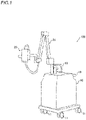
- FIGS. 1 and 2 The configuration of a treatment support apparatus 100 according to the embodiment is now described with reference to FIGS. 1 and 2 .
- the treatment support apparatus 100 (see FIGS. 1 and 2 ) according to this embodiment is an apparatus that supports treatment of photoimmunotherapy.
- the treatment support apparatus 100 is configured to generate a fluorescence distribution image 41 (see FIG. 3 ), which is an image showing a fluorescence distribution state, by irradiating a cancer patient 200 (see FIG. 2 ) with excitation light and detecting fluorescence (see FIG. 7 ) emitted by a fluorescent substance 301 (see FIGS. 7 and 8 ) of a drug 300 (see FIG. 2 ) administered into the body of the cancer patient 200.
- the cancer patient 200 is an example of a "subject" in the claims. The details of photoimmunotherapy are described below.
- An operator such as a doctor can confirm, with the treatment support apparatus 100, how the drug 300 containing the fluorescent substance 301 is distributed in the body of the cancer patient 200 and how much the drug 300 is accumulated in the body of the cancer patient 200 before the treatment of photoimmunotherapy.
- the operator such as a doctor can grasp, with the treatment support apparatus 100, the effect of the treatment from the distribution and accumulation of the drug 300 containing the fluorescent substance 301 in the body of the cancer patient 200 after the treatment of the photoimmunotherapy.
- the treatment support apparatus 100 is also configured to perform treatment to kill cancer cells 201 by photoimmunotherapy (treatment to kill the cancer cells 201 based on irradiating the drug 300 containing the fluorescent substance 301 with light in a specific waveband) by continuously radiating the light in the specific waveband according to the fluorescent substance 301, in addition to support for the treatment of photoimmunotherapy.
- the treatment support apparatus 100 includes an apparatus main body 10, an imager 20, and an arm unit 30.
- the apparatus main body 10 includes a plurality of wheels 11, a handle 12, and a display 13.
- the imager 20 is connected to the apparatus main body 10 via the arm unit 30.
- the apparatus main body 10 is connected to one end of the arm unit 30, and the imager 20 is connected to the other end of the arm unit 30.
- the treatment support apparatus 100 is configured such that the excitation light irradiation direction (imaging direction) and the imaging position of the imager 20 can be adjusted by the arm unit 30.
- Each of the plurality of wheels 11 is provided on a lower portion of the apparatus main body 10, and is configured to rotate.
- the handle 12 is configured to be grippable, and is installed such that the operator such as a doctor can grip the handle 12 when moving the treatment support apparatus 100.
- the display 13 is configured to display the fluorescence distribution image 41 (see FIG. 3 ), a visible light image 42 (see FIG. 4 ), and a composite image 43 (see FIG. 5 ), which are described below.
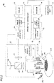
- the imager 20 of the treatment support apparatus 100 includes an excitation light source 21, a white light source 22, and a light source controller 23 (see FIG. 2 ). Furthermore, the imager 20 includes a lens 24, a prism 25, a fluorescence detector 26, and a visible light detector 27 (see FIG. 2 ).
- the excitation light source 21 is configured to radiate excitation light in a specific waveband that excites the fluorescent substance 301 contained in the drug 300.
- the excitation light source 21 includes a semiconductor laser (LD: laser diode) or a light emitting diode (LED: light emitting diode), for example.
- LD semiconductor laser
- LED light emitting diode
- the operator such as a doctor adjusts the excitation light irradiation direction of the imager 20 such that the excitation light of the excitation light source 21 is radiated from outside the body of the cancer patient 200 toward an affected area of the cancer patient 200.
- the specific waveband of the excitation light radiated when the fluorescent substance 301 contained in the drug 300 is excited may be the same as the specific waveband of the light (therapeutic light) radiated to the fluorescent substance 301 of the drug 300 during the treatment of photoimmunotherapy (the treatment to kill the cancer cells 201 based on irradiating the drug 300 containing the fluorescent substance 301 with the light in the specific waveband), or may be a waveband that does not partially overlap the specific waveband of the therapeutic light.
- the half-value width of the spectrum of the excitation light in the specific waveband radiated when the fluorescent substance 301 is excited may be different from the half-value width of the spectrum of the therapeutic light in the specific waveband.
- the white light source 22 is a light source that emits visible light, and is configured to radiate white light.
- the white light source 22 includes a light emitting diode or a fluorescent lamp, for example.
- the white light radiated from the white light source 22 is radiated from outside the body of the cancer patient 200 toward the affected area of the cancer patient 200.
- the light source controller 23 is configured or programmed to control the excitation light source 21 to be turned on and off (to radiate the excitation light and stop radiating the excitation light). Furthermore, the light source controller 23 is configured or programmed to control the white light source 22 to be turned on and off (to radiation the excitation light and stop radiating the excitation light).
- the light source controller 23 is connected to an apparatus controller 14, and is configured or programmed to control irradiation with the excitation light by the excitation light source 21 and control irradiation with the white light by the white light source 22 based on an instruction from the apparatus controller 14.
- the apparatus controller 14 controls irradiation with the excitation light by the excitation light source 21 and controls irradiation with the white light by the white light source 22 via the light source controller 23.
- the apparatus controller 14 is an example of a "controller" in the claims.
- the light source controller 23 and the apparatus controller 14 may be integrally configured.
- the lens 24 is configured such that the fluorescence generated by the fluorescent substance 301 of the drug 300 and the visible light (reflected light) reflected by the cancer patient 200 are incident thereon.
- the fluorescence and the visible light incident on the lens 24 are converged by the lens 24, and are incident on the prism 25.
- the prism 25 is configured to separate the incident light, and the visible light and the fluorescence incident on the lens 24 are separated by the prism 25.
- the fluorescence separated by the prism 25 forms an image in the fluorescence detector 26.
- the visible light separated by the prism 25 forms an image in the visible light detector 27.
- the fluorescence detector 26 is configured to detect fluorescence.
- the fluorescence detector 26 is an imaging device that detects the fluorescence emitted by the fluorescent substance 301 and separated by the prism 25.
- the fluorescence detector 26 images the fluorescence emitted by the fluorescent substance 301 by excitation with excitation light at the frame rate (30 frames/second (60 fields/second)) of National Television System Commission (NTSC) standards.
- NTSC National Television System Commission
- the visible light detector 27 is configured to detect visible light.
- the visible light detector 27 is an imaging device that detects the visible light (reflected light) reflected by the cancer patient 200 and separated by the prism 25.
- the visible light detector 27 images the visible light reflected from the cancer patient 200 at the frame rate (30 frames/second (60 fields/second)) of NTSC standards.
- the apparatus controller 14 is electrically connected to the display 13, an operation unit 15, an image generator 16, an image synthesizer 17, a storage 18, the light source controller 23, a light source controller 53, and an information output 55 (see FIG. 2 ).
- the information output 55 is an example of a "distribution information output" in the claims.
- the apparatus controller 14 includes a central processing unit (CPU), a read-only memory (ROM), a random access memory (RAM), etc., and is configured to control the entire treatment support apparatus 100.
- CPU central processing unit
- ROM read-only memory
- RAM random access memory
- the operation unit 15 is a user interface for operating the treatment support apparatus 100.
- the operation unit 15 is configured to receive operations for controlling the treatment support apparatus 100 to turn on and off the excitation light source 21 (to radiate the excitation light and stop radiating the excitation light), to turn on and off the white light source 22 (to radiate the excitation light and stop radiating the excitation light), and to determine a display method for an image displayed on the display 13.
- the treatment support apparatus 100 includes the image generator 16 (see FIG. 2 ).
- a signal output by the fluorescence detector 26 based on the detected fluorescence and a signal output by the visible light detector 27 based on the detected visible light are input to the image generator 16.
- the image generator 16 is configured to generate an image based on the input signals.
- the image generator 16 is configured to generate the fluorescence distribution image 41 (see FIG. 3 ), which is an image showing the distribution state of the fluorescence emitted by the fluorescent substance 301, based on the fluorescence from the fluorescent substance 301 detected by the fluorescence detector 26.
- the image generator 16 is configured to generate the visible light image 42 (see FIG. 4 ) based on the visible light detected by the visible light detector 27.
- the image synthesizer 17 is configured to generate the composite image 43 (see FIG. 5 ) in which the fluorescence distribution image 41 generated by the image generator 16 and the visible light image 42 generated by the image generator 16 are superimposed. That is, the image synthesizer 17 is configured to generate the composite image 43 in which a plurality of images generated by the image generator 16 are superimposed.
- the apparatus controller 14 is configured or programmed to perform a control to display the composite image 43 on the display 13.
- the display 13 is configured to display the fluorescence distribution image 41 and the visible light image 42 in addition to the composite image 43 under the control of the apparatus controller 14.
- the display 13 may switchingly display any one of the fluorescence distribution image 41, the visible light image 42, and the composite image 43, or may display any two or all of the fluorescence distribution image 41, the visible light image 42, and the composite image 43 side by side at the same time.
- the storage 18 is configured to store the fluorescence distribution image 41, the visible light image 42, the composite image 43, etc. In addition, the storage 18 is configured to store a program executed by the apparatus controller 14 to control excitation light irradiation and data required to control the excitation light irradiation when the fluorescence distribution image 41 is generated before or after the treatment.
- the treatment support apparatus 100 includes an excitation light source 51, an optical fiber 52, the light source controller 53, a fluorescence detector 54, and the information output 55 (see FIG. 2 ).
- the excitation light source 51 is configured to radiate excitation light in a specific waveband that excites the fluorescent substance 301 contained in the drug 300.
- the excitation light source 51 includes a semiconductor laser or a light emitting diode, for example.
- the optical fiber 52 is a composite-type (bidirectional) optical fiber 52 capable of guiding the light from the excitation light source 51 to the outside of the optical fiber 52 and guiding the light from the outside of the optical fiber 52 to the fluorescence detector 54.
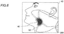
- the optical fiber 52 is inserted into the body of the cancer patient 200 (see FIGS. 2 and 6 ).
- the optical fiber 52 is configured to guide and radiate the excitation light from the excitation light source 51 in the body of the cancer patient 200 to excite the fluorescent substance 301 of the drug 300 and guide the fluorescence generated from the fluorescent substance 301 to the fluorescence detector 54.
- the fluorescence generated by the fluorescent substance 301 excited by the excitation light radiated from the excitation light source 21 may be guided to the fluorescence detector 54 by the optical fiber 52.
- the treatment support apparatus 100 can also perform the treatment to kill the cancer cells 201 by continuously radiating the light in the specific waveband in the body of the cancer patient 200 (see FIGS. 2 and 6 ) using the optical fiber 52.
- the light source controller 53 is configured or programmed to control the optical fiber 52 to be turned on and off (to radiate the excitation light and stop radiating the excitation light). Furthermore, the light source controller 53 is connected to the apparatus controller 14, and is configured or programmed to control irradiation with the excitation light in the body of the cancer patient 200 by the excitation light source 51 via the optical fiber 52 based on an instruction from the apparatus controller 14.
- the light source controller 53 and the apparatus controller 14 may be integrally configured, or the light source controller 53 and the light source controller 23 may be integrally configured.
- the fluorescence detector 54 is configured to detect fluorescence.
- the fluorescence detector 54 is an imaging device that detects the fluorescence emitted by the fluorescent substance 301 and guided by the optical fiber 52.
- the fluorescence detector 54 images the fluorescence emitted by the fluorescent substance 301 at the frame rate (30 frames/second (60 fields/second)) of NTSC standards.
- the information output 55 outputs information about the distribution state of the fluorescence emitted by the fluorescent substance 301 based on the fluorescence from the fluorescent substance 301 detected by the fluorescence detector 54.
- the information output 55 outputs the information about the distribution state of the fluorescence emitted by the fluorescent substance 301 based on the fluorescence from the fluorescent substance 301 detected by the fluorescence detector 54. That is, the information output 55 is configured to output the information about the distribution state of the fluorescence based on information about the fluorescence guided by the optical fiber 52 and then detected by the fluorescence detector 54. Furthermore, the information output 55 may acquire positional information about the optical fiber 52 inserted into the body of the cancer patient 200 in addition to the information about the fluorescence detected by the fluorescence detector 54, and output the information about the distribution state of the fluorescence.
- the positional information about the optical fiber 52 may be acquired based on the visible light image 42. Alternatively, a sensor such as a motion sensor may be provided on the optical fiber 52, and the positional information about the optical fiber 52 may be acquired based on information such as acceleration detected by the sensor.
- the information output 55 may be configured to output a detection of fluorescence intensity at or above a threshold as a sound, and notify the operator such as a doctor of the information about the distribution state of the fluorescence when the fluorescence intensity detected by the fluorescence detector 54 is equal to or more than a preset threshold. Furthermore, the information about the distribution state of the fluorescence output from the information output 55 may be displayed on the display 13 under the control of the apparatus controller 14.
- Photoimmunotherapy in which the treatment support apparatus 100 supports the treatment is now described with reference to FIGS. 7 and 8 .
- the drug 300 (see FIGS. 2 , 7, and 8 ) is administered into the body of the cancer patient 200 (see FIGS. 2 and 4 ) before the treatment.
- the drug 300 contains the fluorescent substance 301 that emits fluorescence and an antibody 302 (see FIGS. 7 and 8 ).
- the fluorescent substance 301 is a substance that is excited and emits fluorescence when irradiated with the light in the specific waveband.
- the fluorescent substance 301 is a chemical substance such as IRDye (registered trademark) 700DX, for example.
- IRDye 700DX is excited by light having a wavelength of 600 nm or more and 700 nm or less, and emits light having a wavelength of about 700 nm or 770 nm as fluorescence.
- the fluorescent substance 301 is a substance that causes a photochemical reaction when continuously irradiated with the light in the specific waveband.
- photoimmunotherapy the treatment that kills the cancer cells 201 based on irradiating the drug 300 containing the fluorescent substance 301 with the light in the specific waveband
- the light in the specific waveband in which the fluorescent substance 301 causes a photochemical reaction according to the type of the fluorescent substance 301 of the drug 300 administered into the cancer patient 200 is radiated to the affected area of the cancer patient 200 (the fluorescent substance 301 of the drug 300 administered into the cancer patient 200).
- the light in the specific waveband radiated during the treatment is light in a waveband in which the fluorescent substance 301 of the drug 300 used for the treatment causes a photochemical reaction in a region from a portion of visible light to near-infrared light (600 nm or more and 2500 nm or less), and varies depending on the type of the fluorescent substance 301 of the drug 300 used for the treatment.
- IRDye 700DX is used as the fluorescent substance 301
- light having a wavelength of 600 nm or more and 700 nm or less, e.g., non-thermal red light having a wavelength of about 690 nm is radiated during the treatment of photoimmunotherapy (see FIG. 7 ).
- the antibody 302 selectively binds to an antigen 202 of the cancer cells 201 (a specific protein expressed on the cancer cells 201). Therefore, the antibody 302 is selected according to the antigen 202 of the cancer cells 201 to be treated.
- the antibody 302 is an antibody such as cetuximab, for example.
- the drug 300 administered into the cancer patient 200 enters the bloodstream, circulates in the body of the cancer patient 200, and selectively binds to the antigen 202 of the cancer cells 201 via the antibody 302.
- the fluorescent substance 301 of the drug 300 causes a photochemical reaction when continuously irradiated with the light in the specific waveband according to the fluorescent substance 301, and the chemical structure of the fluorescent substance 301 is changed.
- the change in the chemical structure of the fluorescent substance 301 causes a change in the three-dimensional structure of the antibody 302 (see FIG. 8 ). Then, the change in the three-dimensional structure of the antibody 302 that has bound to the cancer cells 201 damages the cell membranes of the cancer cells 201 (see FIG. 8 ) to which the antibody 302 has bound.
- the fluorescent substance 301 does not emit fluorescence after the chemical structure thereof is changed by the photochemical reaction.
- the operator such as a doctor can confirm how the drug 300 containing the fluorescent substance 301 is distributed in the body of the cancer patient 200 and how much the drug 300 is accumulated in the body of the cancer patient 200 by observing a fluorescence distribution 40 in the composite image 43 displayed on the display 13 or the fluorescence distribution 40 in the fluorescence distribution image 41.
- the apparatus controller 14 is configured or programmed to perform a control to distinguishably display the visible light image 42 and the fluorescence distribution 40 which have been superimposed in the composite image 43 in order to allow the operator such as a doctor to easily confirm the fluorescence distribution 40 in the composite image 43.
- the apparatus controller 14 performs a control to distinguishably display the visible light image 42 and the fluorescence distribution 40 by setting a display color of the fluorescence distribution 40 to a color that can be easily distinguished from the visible light image 42 (a fluorescent color such as green, purple, or blue, or a color different from the skin, tissue, and blood color of the cancer patient 200, for example) or blinking the fluorescence distribution 40, for example.
- the apparatus controller 14 may be configured or programmed to set a threshold for the detected fluorescence intensity or a total value of the detected intensity, for example, and control the display 13 to change a display method for the fluorescence distribution 40 or provide a display to notify that it has become equal to or more than the threshold when it has become equal to or more than the threshold.
- the operator such as a doctor inserts the optical fiber 52 into the body of the cancer patient 200 for the treatment and starts the treatment to kill the cancer cells 201 based on radiating the light in the specific waveband.
- the fluorescent substance 301 of the drug 300 does not emit fluorescence after the chemical structure thereof is changed by the photochemical reaction, and thus the fluorescence distribution 40 changes as the treatment progresses. That is, the operator such as a doctor can grasp the progress of the treatment by the fluorescence distribution 40 in the composite image 43 (see FIG. 6 ) during the treatment or a change in the fluorescence distribution 40 in the fluorescence distribution image 41 during the treatment.
- the operator such as a doctor can grasp a distribution of the drug 300 containing fluorescent substance 301 in the body of cancer patient 200, and the therapeutic effect from accumulation by confirming the fluorescence distribution 40 in the composite image 43 displayed on the display 13, or the fluorescence distribution 40 in the fluorescence distribution image 41 as before the treatment.
- the light (therapeutic light) in the specific waveband radiated for the treatment may be radiated from the excitation light source 21 while also serving as the excitation light, or may be radiated from an apparatus different from the treatment support apparatus 100.
- the excitation light source 21 irradiates the fluorescent substance 301 of the drug 300 administered into the body of the cancer patient 200 with the excitation light in the specific waveband with energy that excites the fluorescent substance 301 but does not kill the cancer cells 201 (irradiates the fluorescent substance 301 with the excitation light in the specific waveband having energy that does not kill the cancer cells 201).
- the energy that does not kill the cancer cells 201 refers to the integrated amount of energy obtained by integrating the irradiation intensity of the excitation light and the irradiation time of the excitation light.
- the energy that does not kill the cancer cells 201 varies depending on the site of the cancer and the drug 300 used for the treatment, for example, but can be confirmed in advance by a test or the like.
- the states of the cancer cells 201 are observed with a microscope or the like while the cancer cells 201 to which the drug 300 has bound are irradiated with the light in the waveband in which the fluorescent substance 301 of the drug 300 causes a photochemical reaction such that the integrated amount of energy that does not kill the cancer cells 201 (does not cause the death of the cancer cells 201 to start) can be confirmed.
- the integrated amount of energy given during the treatment is 100 J/cm 2 .
- the integrated amount of energy that does not kill the cancer cells 201 is about 0.5 J/cm 2 , which is about 1/200 of the integrated amount of energy given during the treatment.
- the apparatus controller 14 is configured or programmed to control irradiation with the excitation light by the excitation light source 21 such that the integrated amount of energy given to the fluorescent substance 301 by the excitation light is a first integrated energy amount 61 (see FIG. 9 ) when generating the fluorescence distribution image 41 before or after the treatment.
- the first integrated energy amount 61 is an integrated value of the irradiation intensity of the excitation light radiated to the fluorescent substance 301 when the fluorescence distribution image 41 is generated before or after the treatment and the irradiation time of the excitation light.
- the excitation light source 21 is configured to radiate the excitation light such that the first integrated energy amount 61 (see FIG. 9 ), which is the integrated amount of energy given to the fluorescent substance 301 by the excitation light, is smaller than a second integrated energy amount 62 (see FIG. 9 ), which is the integrated amount of energy given to the fluorescent substance 301 by the light in the specific waveband during the treatment, when the fluorescence distribution image 41 is generated before or after the treatment.
- the second integrated energy amount 62 is an integrated value of the irradiation intensity of the light radiated to the fluorescent substance 301 during the treatment and the irradiation time of the radiated light.
- the fluorescent substance 301 does not emit fluorescence after the chemical structure thereof is changed by the photochemical reaction. Therefore, as the treatment to kill the cancer cells 201 based on irradiating the drug 300 containing the fluorescent substance 301 with the light in the specific waveband progresses, the fluorescent substance 301 that emits fluorescence decreases. Furthermore, the first integrated energy amount 61 given to the fluorescent substance 301 by the excitation light radiated by the excitation light source 21 when the fluorescence distribution image 41 is generated is the integrated amount of energy in a range in which the rate of decrease in the fluorescence intensity (the vertical axis in FIG. 9 ) detected by the fluorescence detector 26 as the integrated amount of energy (the horizontal axis in FIG.
- the fluorescence intensity in the first integrated energy amount 61 is not limited to a constant value, but may increase or decrease.
- the first integrated energy amount 61 is determined in a range equal to or less than the integrated energy amount obtained in advance, which does not kill the cancer cells 201 (does not cause the death of the cancer cells 201 to start). For example, when the integrated energy amount obtained in advance, which does not kill the cancer cells 201, is 0.5 J/cm 2 , the first integrated energy amount 61 is determined in a range in which the integrated amount of energy is 0.5 J/cm 2 or less.
- the magnitude of the first integrated energy amount 61 is equal to or more than magnitude that enables the fluorescent substance 301 to be excited, and is less than magnitude that causes the fluorescent substance 301 to change its chemical structure due to the photochemical reaction. That is, the magnitude of the first integrated energy amount 61 is magnitude at which the fluorescent substance 301 of the drug 300 emits fluorescence, and is magnitude at which the fluorescence emitted by the fluorescent substance 301 can be detected and the chemical structure of the fluorescent substance 301 is not changed. Therefore, the chemical structure of the fluorescent substance 301 is not changed, and thus the three-dimensional structure of the antibody 302 is not changed. In addition, the cancer cells 201 are not destroyed (killed) by the drug 300, and even if the cancer cells 201 are destroyed (killed), very few cancer cells 201 are destroyed (killed).
- the irradiation intensity of the excitation light radiated when the fluorescence distribution image 41 is generated before or after the treatment is equal to or higher than the irradiation intensity of the light radiated during the treatment.
- the irradiation intensity of the light in the specific wavelength radiated during the treatment is 150 mW/cm 2
- the irradiation intensity of the excitation light radiated when the fluorescence distribution image 41 is generated before or after the treatment is 150 mW/cm 2 or more.
- the irradiation intensity of the light (therapeutic light) in the specific wavelength radiated during the treatment is 200 mW/cm 2
- the irradiation intensity of the excitation light radiated when the fluorescence distribution image 41 is generated before or after the treatment is 200 mW/cm 2 or more.
- the apparatus controller 14 is configured or programmed to control the excitation light source 21 to radiate excitation light with a predetermined pulse width based on the first integrated energy amount 61 when the fluorescence distribution image 41 is generated before or after the treatment.
- the apparatus controller 14 controls the excitation light source 21 to radiate the excitation light with the predetermined pulse width via the light source controller 23 each time the operator such as a doctor performs an operation.
- the fluorescence detector 26 is configured to detect fluorescence in synchronization with a predetermined pulse in which the excitation light is radiated. Therefore, the minimum value of the predetermined pulse width is changed based on a value of the speed of an imaging process in the fluorescence detector 26.
- the apparatus controller 14 is configured or programmed to change settings of the irradiation time and the irradiation intensity of the excitation light source 21 such that the irradiation intensity of the excitation light radiated by the excitation light source 21 is maximized based on the number of times of imaging set (input) by the operator such as a doctor based on the first integrated energy amount 61.
- the irradiation time per irradiation is set to a minimum value, e.g., 100 ms, and the irradiation intensity of the excitation light radiated by the excitation light source 21 is set to a maximum value of 200 mW/cm 2 (see FIG. 10 ).
- the storage 18 stores the first integrated energy amount 61 according to various treatment conditions such as the type of the excitation light source 21, the type of the drug 300, the type of the cancer, the site of the cancer, and information about the depth of the cancer, and the irradiation intensity that is optimum for generating the fluorescence distribution image 41 according to the treatment conditions.
- the apparatus controller 14 may be configured or programmed to automatically set the irradiation intensity, the irradiation time, and the number of times of irradiation according to the treatment conditions based on the first integrated energy amount 61 and the optimum irradiation intensity according to the treatment conditions, for example, or may be configured or programmed such that the operator such as a doctor sets the irradiation intensity, the irradiation time, and the number of times of irradiation within a range that does not exceed the first integrated energy amount 61 according to the treatment conditions.
- the apparatus controller 14 is configured or programmed to switch settings of the irradiation intensity, the irradiation time, and the number of times of irradiation of the excitation light by the method described above.
- the apparatus controller 14 is configured or programmed to perform a control to limit the irradiation intensity, the irradiation time, and the number of times of irradiation of the excitation light from the excitation light source 21 based on the first integrated energy amount 61.
- the apparatus controller 14 is configured or programmed to limit irradiation with the excitation light by the excitation light source 21 when the integrated amount of energy of the excitation light radiated during observation of the fluorescence distribution before or after the treatment is likely to exceed the integrated amount of energy determined based on the first integrated energy amount 61 in order to significantly reduce or prevent the progress of the treatment during the observation of the fluorescence distribution before or after the treatment (when the fluorescence distribution image 41 is generated before or after the treatment).
- the integrated amount of energy determined based on the first integrated energy amount 61 may be the same as the first integrated energy amount 61, and when it is equal to or more than the magnitude that enables the fluorescent substance 301 to be excited, it may be less than the first integrated energy amount 61.
- the apparatus controller 14 is configured or programmed to perform a control to limit irradiation with the excitation light such that the excitation light is not radiated even when the operator such as a doctor performs an operation when the number of times of irradiation that can be performed in the integrated amount of energy determined based on the first integrated energy amount 61 reaches an upper limit in the case in which the excitation light with the predetermined pulse width is radiated each time the operator such as a doctor performs an operation.
- the apparatus controller 14 is configured or programmed to perform a control to limit irradiation with the excitation light by stopping irradiation with the excitation light (turning off the excitation light source 21) when the irradiation time of the excitation light is long and the integrated amount of energy given to the fluorescent substance 301 by the excitation light is likely to exceed the integrated amount of energy determined based on the first integrated energy amount 61 in a case in which the excitation light is continuously radiated.
- the apparatus controller 14 is configured or programmed to perform a control to limit the irradiation intensity of the excitation light (reduce the irradiation intensity of the excitation light) when the irradiation intensity of the excitation light is high and the integrated amount of energy given to the fluorescent substance 301 by irradiation with the excitation light exceeds the integrated amount of energy determined based on the first integrated energy amount 61.
- the limitation on the irradiation with the excitation light by the apparatus controller 14 may be released by the operation of the operator such as a doctor, if necessary. Furthermore, the control of the irradiation with the excitation light by the apparatus controller 14 as described above is performed not only on the excitation light source 21 but also on the excitation light source 51 via the light source controller 53, for example.
- the excitation light source 21 irradiates the fluorescent substance 301 of the drug 300 with the excitation light in the specific waveband having energy that excites the fluorescent substance 301 but does not kill the cancer cells 201, and the image generator 16 generates the fluorescence distribution image 41, which is an image showing the distribution state of the fluorescence emitted by the fluorescent substance 301, based on the fluorescence from the fluorescent substance 301.
- the fluorescence distribution image 41 which is an image showing the distribution state of the fluorescence emitted by the fluorescent substance 301, can be generated in a state in which the fluorescent substance 301 is excited without killing the cancer cells 201 (without proceeding with the treatment), and thus using the fluorescence distribution image 41 generated by the image generator 16, the distribution state of the drug 300 that binds to the cancer cells 201 can be visually and easily confirmed.
- the treatment support apparatus 100 and an image generation method each of which enables the distribution state of the drug 300 that binds to the cancer cells 201 to be confirmed before or after the treatment to kill the cancer cells 201 based on irradiating the drug 300 that binds to the cancer cells 201 with the light in the specific waveband.
- the excitation light source 21 radiates the excitation light such that the first integrated energy amount 61, which is the integrated amount of energy given to the fluorescent substance 301 by the excitation light, is smaller than the second integrated energy amount 62, which is the integrated amount of energy given to the fluorescent substance 301 by the light in the specific waveband during the treatment when the fluorescence distribution image 41 is generated before or after the treatment. Accordingly, when the fluorescence distribution image 41 is generated before or after the treatment, the integrated amount of energy given to the fluorescent substance 301 by the excitation light (first integrated energy amount 61) can be prevented from exceeding the integrated amount of energy given to the fluorescent substance 301 by the light in the specific waveband during the treatment (second integrated energy amount 62). Consequently, it is possible to prevent the treatment from being unintentionally started when the fluorescence distribution image 41 is generated before or after the treatment.
- the first integrated energy amount 61 is the integrated amount of energy in the range in which the rate of decrease in the fluorescence intensity detected by the fluorescence detector 26 as the integrated amount of energy given to the fluorescent substance 301 increases is smaller than the rate of decrease in the fluorescence intensity during the treatment detected by the fluorescence detector 26 as the integrated amount of energy during the treatment given to the fluorescent substance 301 by the light in the specific waveband increases.
- the rate of decrease in the fluorescence intensity detected by the fluorescence detector 26 as the integrated amount of energy increases is smaller than the rate of decrease in the fluorescence intensity during the treatment detected by the fluorescence detector 26 as the integrated amount of energy during the treatment given to the fluorescent substance 301 by the light in the specific waveband increases. Consequently, it is possible to confirm the distribution 40 of the fluorescence emitted by the fluorescent substance 301 of the drug 300 before the treatment progresses and the fluorescence intensity decreases.
- the magnitude of the first integrated energy amount 61 is equal to or more than the magnitude that enables the fluorescent substance 301 to be excited, and is less than the magnitude that causes the fluorescent substance 301 to change its chemical structure due to the photochemical reaction. Accordingly, the fluorescence detector 26 can detect the fluorescence emitted from the fluorescent substance 301 of the drug 300, and the death of the cancer cells 201 due to the photochemical reaction of the fluorescent substance 301 of the drug 300 caused by irradiation with the excitation light can be significantly reduced or prevented.
- the second integrated energy amount 62 is the integrated value of the irradiation intensity of the light radiated to the fluorescent substance 301 during the treatment and the irradiation time of the radiated light
- the first integrated energy amount 61 is the integrated value of the irradiation intensity of the excitation light radiated to the fluorescent substance 301 when the fluorescence distribution image 41 is generated before or after the treatment and the irradiation time of the excitation light.
- the apparatus controller 14 controls irradiation with the excitation light by the excitation light source 21 such that the integrated amount of energy given to the fluorescent substance 301 by the excitation light becomes the first integrated energy amount 61 when the fluorescence distribution image 41 is generated before or after the treatment.
- the first integrated energy amount 61 is based on the integrated value of the irradiation intensity of the excitation light radiated to the fluorescent substance 301 and the irradiation time of the excitation light, and thus when the fluorescence distribution image 41 is generated before or after the treatment, the irradiation intensity of the excitation light and the irradiation time of the excitation light are controlled such that the integrated amount of energy given to the fluorescent substance 301 by the excitation light can be easily controlled within the range of the first integrated energy amount 61. Consequently, the apparatus controller 14 can more easily control irradiation with the excitation light such that the first integrated energy amount 61 does not exceed the second integrated energy amount 62 when the fluorescence distribution image 41 is generated before or after the treatment.
- the apparatus controller 14 performs a control to limit the irradiation intensity, the irradiation time, and the number of times of irradiation of the excitation light from the excitation light source 21 based on the first integrated energy amount 61. Accordingly, it is possible to prevent the integrated amount of energy given to the fluorescent substance 301 by the excitation light from exceeding the first integrated energy amount 61 by increases in the irradiation intensity, the irradiation time, and the number of times of irradiation of the excitation light when the fluorescence distribution image 41 is generated before or after the treatment.
- the image generator 16 is configured to generate the visible light image 42 based on the visible light detected by the visible light detector 27, and the image synthesizer 17 is configured to generate the composite image 43 in which the fluorescence distribution image 41 and the visible light image 42 are superimposed.
- the apparatus controller 14 controls the apparatus controller 14 (controller) performs a control to display at least the composite image 43 on the display 13. Accordingly, the composite image 43 in which the fluorescence distribution image 41 before or after the treatment and the visible light image 42 are superimposed can be displayed on the display 13, and thus the fluorescence distribution image 41 and the visible light image 42 can be easily compared.
- the apparatus controller 14 controls the excitation light source 21 to radiate the excitation light with the predetermined pulse width based on the first integrated energy amount 61 when the fluorescence distribution image 41 is generated before or after the treatment. Accordingly, the excitation light with the pulse width based on the first integrated energy amount 61 is radiated, and thus the irradiation time of the excitation light radiated by the excitation light source 21 when the fluorescence distribution image 41 is generated before or after the treatment can be reduced. Consequently, the irradiation intensity of the excitation light can be increased within the range that does not exceed the first integrated energy amount 61.
- the irradiation intensity of the excitation light radiated when the fluorescence distribution image 41 is generated before or after the treatment is equal to or higher than the irradiation intensity of the light radiated during the treatment. Accordingly, when the fluorescence distribution image 41 is generated before or after the treatment, the excitation light with an irradiation intensity equal to the irradiation intensity of the light radiated during the treatment is radiated such that it is possible to confirm the distribution state of the drug 300 up to a depth position equivalent to a depth position reached by the light radiated during the treatment.
- the excitation light with an irradiation intensity higher than the irradiation intensity of the light radiated during the treatment is radiated such that it is possible to confirm the distribution state of the drug 300 up to a depth position deeper than the depth position reached by the light radiated during the treatment.
- the excitation light source 51 irradiates the fluorescent substance 301 of the drug 300 with the excitation light in the specific waveband having energy that excites the fluorescent substance 301 but does not kill the cancer cells 201 before or after the treatment
- the information output 55 distributed information output
- the information output 55 outputs the information about the distribution state of the fluorescence emitted by the fluorescent substance 301 based on the fluorescence from the fluorescent substance 301.
- the information about the distribution state of the fluorescence emitted by the fluorescent substance 301 can be output in a state in which the fluorescent substance 301 is excited without killing the cancer cells 201 (without proceeding with the treatment), and thus using the information about the distribution state of the fluorescence output by the information output 55, the distribution state of the drug 300 that binds to the cancer cells 201 can be confirmed. Consequently, it is possible to provide the treatment support apparatus 100 that enables the distribution state of the drug 300 that binds to the cancer cells 201 to be confirmed before or after the treatment to kill the cancer cells 201 based on irradiating the drug 300 that binds to the cancer cells 201 with the light in the specific waveband.
- the treatment support apparatus 100 includes the display 13 configured to display the composite image 43
- the present invention is not limited to this.
- the treatment support apparatus may be configured to output a composite image or the like to a monitor or the like outside the apparatus, which displays the composite image or the like, without including the display.
- the present invention is not limited to this.
- the present invention as in a first modified example shown in FIG.
- the irradiation intensity of the excitation light radiated when the fluorescence distribution image is generated before or after the treatment may be set to be lower than the irradiation intensity of the light radiated during the treatment (the irradiation intensity of the excitation light radiated when the fluorescence distribution image is generated before or after the treatment may be set to 50 mW/cm 2 when the irradiation intensity of the light in the specific wavelength radiated during the treatment is 200 mW/cm 2 , for example), and the excitation light may be continuously radiated.
- a white light source and a visible light detector may not be provided, and only a fluorescence distribution image may be generated by an image generator based on fluorescence from a fluorescent substance detected by a fluorescence detector.
- the present invention is not limited to this.
- irradiation with excitation light and detection of fluorescence emitted by a fluorescent substance of a drug may be performed in the body of a cancer patient 200 via an optical fiber 52.
- the treatment support apparatus 100 is configured to perform treatment in addition to support for the treatment
- the present invention is not limited to this.
- the treatment support apparatus may be configured to only support the treatment of photoimmunotherapy (only generate the fluorescence distribution image or only output the information about the fluorescence distribution state).
- a treatment support apparatus comprising:
- the treatment support apparatus wherein the excitation light source is configured to radiate the excitation light such that a first integrated energy amount, which is an integrated amount of energy given to the fluorescent substance by the excitation light, is smaller than a second integrated energy amount, which is an integrated amount of energy given to the fluorescent substance by the light in the specific waveband during the treatment when the fluorescence distribution image is generated before or after the treatment.
- a first integrated energy amount which is an integrated amount of energy given to the fluorescent substance by the excitation light
- a second integrated energy amount which is an integrated amount of energy given to the fluorescent substance by the light in the specific waveband during the treatment when the fluorescence distribution image is generated before or after the treatment.
- the first integrated energy amount given to the fluorescent substance by the excitation light emitted by the excitation light source is an integrated amount of energy in a range in which a rate of decrease in a fluorescence intensity detected by the fluorescence detector as the integrated amount of the energy given to the fluorescent substance increases is smaller than a rate of decrease in a fluorescence intensity during the treatment detected by the fluorescence detector as the integrated amount of the energy during the treatment given to the fluorescent substance by the light in the specific waveband increases.
- a magnitude of the first integrated energy amount is equal to or more than a magnitude that enables the fluorescent substance to be excited, and is less than a magnitude that causes the fluorescent substance to change a chemical structure thereof due to a photochemical reaction.
- the treatment support apparatus according to any one of items 2 to 4, further comprising:
- the treatment support apparatus wherein the controller is configured or programmed to perform a control to limit an irradiation intensity, an irradiation time, and a number of times of irradiation of the excitation light from the excitation light source based on the first integrated energy amount.
- the treatment support apparatus according to item 5 or 6, further comprising:
- the treatment support apparatus according to item 6 or 7, wherein the controller is configured or programmed to control the excitation light source to radiate the excitation light with a predetermined pulse width based on the first integrated energy amount when the fluorescence distribution image is generated before or after the treatment.
- the treatment support apparatus wherein the irradiation intensity of the excitation light radiated when the fluorescence distribution image is generated before or after the treatment is equal to or higher than the irradiation intensity of the light radiated during the treatment.
- a treatment support apparatus comprising:
- An image generation method comprising:
Landscapes
- Health & Medical Sciences (AREA)
- Life Sciences & Earth Sciences (AREA)
- Engineering & Computer Science (AREA)
- Biomedical Technology (AREA)
- Surgery (AREA)
- Public Health (AREA)
- Pathology (AREA)
- Veterinary Medicine (AREA)
- Animal Behavior & Ethology (AREA)
- General Health & Medical Sciences (AREA)
- Biophysics (AREA)
- Radiology & Medical Imaging (AREA)
- Physics & Mathematics (AREA)
- Nuclear Medicine, Radiotherapy & Molecular Imaging (AREA)
- Heart & Thoracic Surgery (AREA)
- Medical Informatics (AREA)
- Molecular Biology (AREA)
- Optics & Photonics (AREA)
- Investigating, Analyzing Materials By Fluorescence Or Luminescence (AREA)
- Radiation-Therapy Devices (AREA)
- Measuring And Recording Apparatus For Diagnosis (AREA)
- Medicines That Contain Protein Lipid Enzymes And Other Medicines (AREA)
Abstract
Description
- The present invention relates to a treatment support apparatus and an image generation method, and more particularly, it relates to a treatment support apparatus and an image generation method in which a drug containing a fluorescent substance is irradiated with light in a specific waveband.
- In recent years, photoimmunotherapy has been attracting attention as a new cancer treatment method. In photoimmunotherapy, a drug containing a fluorescent substance that causes a photochemical reaction and an antibody that selectively binds to cancer cells is first administered into the body of a cancer patient. The administered drug travels through the body of the cancer patient and selectively binds to an antigen of the cancer cells. Next, light in a specific waveband according to the fluorescent substance is radiated such that the fluorescent substance of the drug emits fluorescence and causes a photochemical reaction to change the chemical structure of the fluorescent substance. This change in the chemical structure of the fluorescent substance causes a change in the three-dimensional structure of the antibody. Then, the change in the three-dimensional structure of the antibody that has bound to the cancer cells damages the cell membranes of the cancer cells to which the antibody has bound to destroy (kill) the cancer cells.
- Patent Document 1 discloses displaying an image showing the distribution state of fluorescence emitted by a fluorescent substance of a drug during treatment of photoimmunotherapy, i.e., when cancer cells are killed based on irradiating the drug that binds to the cancer cells with light in a specific waveband.
- Patent Document 1: International Publication No.
2019/215905 - In photoimmunotherapy, in order to enhance the therapeutic effect, it is desirable to confirm the distribution state of the drug before the treatment and start the treatment in a state in which a sufficient amount of drug binds to the cancer cells in the body of a cancer patient. In addition, there is a desire to confirm the presence or absence of the drug that does not cause a photochemical reaction (does not act on the treatment) from the distribution state of the fluorescence emitted by the fluorescent substance of the drug in order to determine whether or not additional treatment is needed after the treatment. Therefore, it is desired to be able to confirm the distribution state of the drug that binds to the cancer cells even during non-treatment (before or after the treatment).
- The present invention is intended to solve the above problems. The present invention aims to provide a treatment support apparatus and an image generation method, each of which enables the distribution state of a drug that binds to cancer cells to be confirmed before or after treatment to kill the cancer cells based on irradiating the drug that binds to the cancer cells with light in a specific waveband.
- In order to attain the aforementioned object, a treatment support apparatus according to a first aspect of the present invention includes an excitation light source configured to irradiate a fluorescent substance of a drug administered into a body of a subject with excitation light in a specific waveband having energy that excites the fluorescent substance but does not kill a cancer cell before or after treatment to kill the cancer cell based on irradiating the drug containing the fluorescent substance with light in a specific waveband, a fluorescence detector configured to detect fluorescence emitted by the fluorescent substance of the drug due to excitation by the excitation light, and an image generator configured to generate a fluorescence distribution image, which is an image showing a distribution state of the fluorescence emitted by the fluorescent substance, based on the fluorescence from the fluorescent substance detected by the fluorescence detector. In the treatment to kill the cancer cell based on irradiating the drug containing the fluorescent substance with the light in the specific waveband, the drug is administered to the subject, and then the light in the specific waveband is continuously radiated such that energy to kill the cancer cell is given to the fluorescent substance of the drug. The fluorescence emitted by the fluorescent substance of the drug may include not only a visible light region but also an infrared light region.
- In order to attain the aforementioned object, a treatment support apparatus according to a second aspect of the present invention includes an excitation light source configured to irradiate a fluorescent substance of a drug administered into a body of a subject with excitation light in a specific waveband having energy that excites the fluorescent substance but does not kill a cancer cell before or after treatment to kill the cancer cell based on irradiating the drug containing the fluorescent substance with light in a specific waveband, a fluorescence detector configured to detect fluorescence emitted by the fluorescent substance of the drug due to excitation by the excitation light, and a distribution information output configured to output information about a distribution state of the fluorescence emitted by the fluorescent substance based on the fluorescence from the fluorescent substance detected by the fluorescence detector.
- In order to attain the aforementioned object, an image generation method according to a third aspect of the present invention includes irradiating a fluorescent substance of a drug administered into a body of a subject with excitation light in a specific waveband having energy that excites the fluorescent substance but does not kill a cancer cell before or after treatment to kill the cancer cell based on irradiating the drug containing the fluorescent substance with light in a specific waveband, detecting fluorescence emitted by the fluorescent substance of the drug due to excitation by the excitation light, and generating a fluorescence distribution image, which is an image showing a distribution state of the fluorescence emitted by the fluorescent substance, based on the detected fluorescence emitted by the fluorescent substance of the drug due to the excitation by the excitation light.
- In the treatment support apparatus according to the first aspect of the present invention, as described above, the excitation light source is configured to radiate the excitation light in the specific waveband having energy that excites the fluorescent substance but does not kill the cancer cell before or after the treatment, and the image generator is configured to generate the fluorescence distribution image, which is an image showing the distribution state of the fluorescence emitted by the fluorescent substance. Accordingly, before or after the treatment, the fluorescence distribution image, which is an image showing the distribution state of the fluorescence emitted by the fluorescent substance, can be generated in a state in which the fluorescent substance is excited without killing the cancer cell (without proceeding with the treatment), and thus using the fluorescence distribution image generated by the image generator, the distribution state of the drug that binds to the cancer cell can be visually and easily confirmed. Consequently, it is possible to provide the treatment support apparatus that enables the distribution state of the drug that binds to the cancer cell to be confirmed before or after the treatment to kill the cancer cell based on irradiating the drug that binds to the cancer cell with the light in the specific waveband.
- In the treatment support apparatus according to the second aspect of the present invention, as described above, the excitation light source is configured to radiate the excitation light in the specific waveband having energy that excites the fluorescent substance but does not kill the cancer cell before or after the treatment, and the distribution information output is configured to output the information about the distribution state of the fluorescence emitted by the fluorescent substance. Accordingly, before or after the treatment, the information about the distribution state of the fluorescence emitted by the fluorescent substance can be output in a state in which the fluorescent substance is excited without killing the cancer cell (without proceeding with the treatment), and thus using the information about the distribution state of the fluorescence output by the distribution information output, the distribution state of the drug that binds to the cancer cell can be confirmed. Consequently, it is possible to provide the treatment support apparatus that enables the distribution state of the drug that binds to the cancer cell to be confirmed before or after the treatment to kill the cancer cell based on irradiating the drug that binds to the cancer cell with the light in the specific waveband.
- In the image generation method according to the third aspect of the present invention, as described above, before or after the treatment, the excitation light in the specific waveband having energy that excites the fluorescent substance but does not kill the cancer cell is radiated, and the fluorescence distribution image, which is an image showing the distribution state of the fluorescence emitted by the fluorescent substance, is generated. Accordingly, before or after the treatment, the fluorescence distribution image, which is an image showing the distribution state of the fluorescence emitted by the fluorescent substance, can be generated in a state in which the fluorescent substance is excited without killing the cancer cell (without proceeding with the treatment), and thus using the generated fluorescence distribution image, the distribution state of the drug that binds to the cancer cell can be visually and easily confirmed. Consequently, it is possible to provide the image generation method that enables the distribution state of the drug that binds to the cancer cell to be confirmed before or after the treatment to kill the cancer cell based on irradiating the drug that binds to the cancer cell with the light in the specific waveband.
-
-
FIG. 1 is a perspective view showing a treatment support apparatus according to an embodiment of the present invention. -
FIG. 2 is a block diagram showing the overall configuration of the treatment support apparatus according to the embodiment of the present invention. -
FIG. 3 is a diagram showing an example of a fluorescence distribution image according to the embodiment of the present invention. -
FIG. 4 is a diagram showing an example of a visible light image according to the embodiment of the present invention. -
FIG. 5 is a diagram showing an example of a composite image according to the embodiment of the present invention. -
FIG. 6 is a diagram showing an example of a composite image during treatment according to the embodiment of the present invention. -
FIG. 7 is a first diagram for illustrating photoimmunotherapy. -
FIG. 8 is a second diagram for illustrating photoimmunotherapy. -
FIG. 9 is a diagram showing an example of the tendency of a decrease in fluorescence intensity with an increase in integrated energy amount. -
FIG. 10 is a diagram showing an example of the irradiation intensity and irradiation time of excitation light radiated when the fluorescence distribution image is generated before or after the treatment by the treatment support apparatus according to the embodiment of the present invention. -
FIG. 11 is a diagram showing an example of the irradiation intensity and irradiation time of excitation light radiated when a fluorescence distribution image is generated before or after treatment by a treatment support apparatus according to a first modified example of the embodiment of the present invention. -
FIG. 12 is a block diagram showing the overall configuration of a treatment support apparatus according to a second modified example of the embodiment of the present invention. -
FIG. 13 is a block diagram showing the overall configuration of a treatment support apparatus according to a third modified example of the embodiment of the present invention. - An embodiment embodying the present invention is hereinafter described on the basis of the drawings.
- The configuration of a
treatment support apparatus 100 according to the embodiment is now described with reference toFIGS. 1 and2 . - The treatment support apparatus 100 (see
FIGS. 1 and2 ) according to this embodiment is an apparatus that supports treatment of photoimmunotherapy. Specifically, thetreatment support apparatus 100 is configured to generate a fluorescence distribution image 41 (seeFIG. 3 ), which is an image showing a fluorescence distribution state, by irradiating a cancer patient 200 (seeFIG. 2 ) with excitation light and detecting fluorescence (seeFIG. 7 ) emitted by a fluorescent substance 301 (seeFIGS. 7 and 8 ) of a drug 300 (seeFIG. 2 ) administered into the body of thecancer patient 200. Thecancer patient 200 is an example of a "subject" in the claims. The details of photoimmunotherapy are described below. - An operator such as a doctor can confirm, with the
treatment support apparatus 100, how thedrug 300 containing thefluorescent substance 301 is distributed in the body of thecancer patient 200 and how much thedrug 300 is accumulated in the body of thecancer patient 200 before the treatment of photoimmunotherapy. In addition, the operator such as a doctor can grasp, with thetreatment support apparatus 100, the effect of the treatment from the distribution and accumulation of thedrug 300 containing thefluorescent substance 301 in the body of thecancer patient 200 after the treatment of the photoimmunotherapy. - The
treatment support apparatus 100 is also configured to perform treatment to killcancer cells 201 by photoimmunotherapy (treatment to kill thecancer cells 201 based on irradiating thedrug 300 containing thefluorescent substance 301 with light in a specific waveband) by continuously radiating the light in the specific waveband according to thefluorescent substance 301, in addition to support for the treatment of photoimmunotherapy. - As shown in
FIG. 1 , thetreatment support apparatus 100 includes an apparatusmain body 10, animager 20, and anarm unit 30. The apparatusmain body 10 includes a plurality ofwheels 11, ahandle 12, and adisplay 13. - The
imager 20 is connected to the apparatusmain body 10 via thearm unit 30. The apparatusmain body 10 is connected to one end of thearm unit 30, and theimager 20 is connected to the other end of thearm unit 30. Thetreatment support apparatus 100 is configured such that the excitation light irradiation direction (imaging direction) and the imaging position of theimager 20 can be adjusted by thearm unit 30. - Each of the plurality of
wheels 11 is provided on a lower portion of the apparatusmain body 10, and is configured to rotate. - The
handle 12 is configured to be grippable, and is installed such that the operator such as a doctor can grip thehandle 12 when moving thetreatment support apparatus 100. - The
display 13 is configured to display the fluorescence distribution image 41 (seeFIG. 3 ), a visible light image 42 (seeFIG. 4 ), and a composite image 43 (seeFIG. 5 ), which are described below. - In this embodiment, the
imager 20 of thetreatment support apparatus 100 includes anexcitation light source 21, awhite light source 22, and a light source controller 23 (seeFIG. 2 ). Furthermore, theimager 20 includes alens 24, aprism 25, afluorescence detector 26, and a visible light detector 27 (seeFIG. 2 ). - The
excitation light source 21 is configured to radiate excitation light in a specific waveband that excites thefluorescent substance 301 contained in thedrug 300. Theexcitation light source 21 includes a semiconductor laser (LD: laser diode) or a light emitting diode (LED: light emitting diode), for example. The operator such as a doctor adjusts the excitation light irradiation direction of theimager 20 such that the excitation light of theexcitation light source 21 is radiated from outside the body of thecancer patient 200 toward an affected area of thecancer patient 200. The specific waveband of the excitation light radiated when thefluorescent substance 301 contained in thedrug 300 is excited may be the same as the specific waveband of the light (therapeutic light) radiated to thefluorescent substance 301 of thedrug 300 during the treatment of photoimmunotherapy (the treatment to kill thecancer cells 201 based on irradiating thedrug 300 containing thefluorescent substance 301 with the light in the specific waveband), or may be a waveband that does not partially overlap the specific waveband of the therapeutic light. Furthermore, the half-value width of the spectrum of the excitation light in the specific waveband radiated when thefluorescent substance 301 is excited may be different from the half-value width of the spectrum of the therapeutic light in the specific waveband. - The
white light source 22 is a light source that emits visible light, and is configured to radiate white light. Thewhite light source 22 includes a light emitting diode or a fluorescent lamp, for example. In order to detect visible light (reflected light) reflected from thecancer patient 200, the white light radiated from thewhite light source 22 is radiated from outside the body of thecancer patient 200 toward the affected area of thecancer patient 200. - The
light source controller 23 is configured or programmed to control theexcitation light source 21 to be turned on and off (to radiate the excitation light and stop radiating the excitation light). Furthermore, thelight source controller 23 is configured or programmed to control thewhite light source 22 to be turned on and off (to radiation the excitation light and stop radiating the excitation light). Thelight source controller 23 is connected to anapparatus controller 14, and is configured or programmed to control irradiation with the excitation light by theexcitation light source 21 and control irradiation with the white light by thewhite light source 22 based on an instruction from theapparatus controller 14. That is, theapparatus controller 14 controls irradiation with the excitation light by theexcitation light source 21 and controls irradiation with the white light by thewhite light source 22 via thelight source controller 23. Theapparatus controller 14 is an example of a "controller" in the claims. Thelight source controller 23 and theapparatus controller 14 may be integrally configured. - The
lens 24 is configured such that the fluorescence generated by thefluorescent substance 301 of thedrug 300 and the visible light (reflected light) reflected by thecancer patient 200 are incident thereon. The fluorescence and the visible light incident on thelens 24 are converged by thelens 24, and are incident on theprism 25. Theprism 25 is configured to separate the incident light, and the visible light and the fluorescence incident on thelens 24 are separated by theprism 25. The fluorescence separated by theprism 25 forms an image in thefluorescence detector 26. The visible light separated by theprism 25 forms an image in thevisible light detector 27. - The
fluorescence detector 26 is configured to detect fluorescence. Thefluorescence detector 26 is an imaging device that detects the fluorescence emitted by thefluorescent substance 301 and separated by theprism 25. Thefluorescence detector 26 images the fluorescence emitted by thefluorescent substance 301 by excitation with excitation light at the frame rate (30 frames/second (60 fields/second)) of National Television System Commission (NTSC) standards. - The
visible light detector 27 is configured to detect visible light. Thevisible light detector 27 is an imaging device that detects the visible light (reflected light) reflected by thecancer patient 200 and separated by theprism 25. Thevisible light detector 27 images the visible light reflected from thecancer patient 200 at the frame rate (30 frames/second (60 fields/second)) of NTSC standards. - The
apparatus controller 14 is electrically connected to thedisplay 13, anoperation unit 15, animage generator 16, animage synthesizer 17, astorage 18, thelight source controller 23, alight source controller 53, and an information output 55 (seeFIG. 2 ). Theinformation output 55 is an example of a "distribution information output" in the claims. - The
apparatus controller 14 includes a central processing unit (CPU), a read-only memory (ROM), a random access memory (RAM), etc., and is configured to control the entiretreatment support apparatus 100. - The
operation unit 15 is a user interface for operating thetreatment support apparatus 100. For example, theoperation unit 15 is configured to receive operations for controlling thetreatment support apparatus 100 to turn on and off the excitation light source 21 (to radiate the excitation light and stop radiating the excitation light), to turn on and off the white light source 22 (to radiate the excitation light and stop radiating the excitation light), and to determine a display method for an image displayed on thedisplay 13. - In this embodiment, the
treatment support apparatus 100 includes the image generator 16 (seeFIG. 2 ). A signal output by thefluorescence detector 26 based on the detected fluorescence and a signal output by thevisible light detector 27 based on the detected visible light are input to theimage generator 16. Theimage generator 16 is configured to generate an image based on the input signals. Theimage generator 16 is configured to generate the fluorescence distribution image 41 (seeFIG. 3 ), which is an image showing the distribution state of the fluorescence emitted by thefluorescent substance 301, based on the fluorescence from thefluorescent substance 301 detected by thefluorescence detector 26. Furthermore, theimage generator 16 is configured to generate the visible light image 42 (seeFIG. 4 ) based on the visible light detected by thevisible light detector 27. - The
image synthesizer 17 is configured to generate the composite image 43 (seeFIG. 5 ) in which thefluorescence distribution image 41 generated by theimage generator 16 and the visiblelight image 42 generated by theimage generator 16 are superimposed. That is, theimage synthesizer 17 is configured to generate thecomposite image 43 in which a plurality of images generated by theimage generator 16 are superimposed. - The
apparatus controller 14 is configured or programmed to perform a control to display thecomposite image 43 on thedisplay 13. Thedisplay 13 is configured to display thefluorescence distribution image 41 and the visiblelight image 42 in addition to thecomposite image 43 under the control of theapparatus controller 14. Thedisplay 13 may switchingly display any one of thefluorescence distribution image 41, the visiblelight image 42, and thecomposite image 43, or may display any two or all of thefluorescence distribution image 41, the visiblelight image 42, and thecomposite image 43 side by side at the same time. - The
storage 18 is configured to store thefluorescence distribution image 41, the visiblelight image 42, thecomposite image 43, etc. In addition, thestorage 18 is configured to store a program executed by theapparatus controller 14 to control excitation light irradiation and data required to control the excitation light irradiation when thefluorescence distribution image 41 is generated before or after the treatment. - The
treatment support apparatus 100 includes anexcitation light source 51, anoptical fiber 52, thelight source controller 53, afluorescence detector 54, and the information output 55 (seeFIG. 2 ). - The
excitation light source 51 is configured to radiate excitation light in a specific waveband that excites thefluorescent substance 301 contained in thedrug 300. Theexcitation light source 51 includes a semiconductor laser or a light emitting diode, for example. - The
optical fiber 52 is a composite-type (bidirectional)optical fiber 52 capable of guiding the light from theexcitation light source 51 to the outside of theoptical fiber 52 and guiding the light from the outside of theoptical fiber 52 to thefluorescence detector 54. Theoptical fiber 52 is inserted into the body of the cancer patient 200 (seeFIGS. 2 and6 ). Theoptical fiber 52 is configured to guide and radiate the excitation light from theexcitation light source 51 in the body of thecancer patient 200 to excite thefluorescent substance 301 of thedrug 300 and guide the fluorescence generated from thefluorescent substance 301 to thefluorescence detector 54. The fluorescence generated by thefluorescent substance 301 excited by the excitation light radiated from theexcitation light source 21 may be guided to thefluorescence detector 54 by theoptical fiber 52. Thetreatment support apparatus 100 can also perform the treatment to kill thecancer cells 201 by continuously radiating the light in the specific waveband in the body of the cancer patient 200 (seeFIGS. 2 and6 ) using theoptical fiber 52. - The
light source controller 53 is configured or programmed to control theoptical fiber 52 to be turned on and off (to radiate the excitation light and stop radiating the excitation light). Furthermore, thelight source controller 53 is connected to theapparatus controller 14, and is configured or programmed to control irradiation with the excitation light in the body of thecancer patient 200 by theexcitation light source 51 via theoptical fiber 52 based on an instruction from theapparatus controller 14. Thelight source controller 53 and theapparatus controller 14 may be integrally configured, or thelight source controller 53 and thelight source controller 23 may be integrally configured. - The
fluorescence detector 54 is configured to detect fluorescence. Thefluorescence detector 54 is an imaging device that detects the fluorescence emitted by thefluorescent substance 301 and guided by theoptical fiber 52. Thefluorescence detector 54 images the fluorescence emitted by thefluorescent substance 301 at the frame rate (30 frames/second (60 fields/second)) of NTSC standards. - The
information output 55 outputs information about the distribution state of the fluorescence emitted by thefluorescent substance 301 based on the fluorescence from thefluorescent substance 301 detected by thefluorescence detector 54. - The
information output 55 outputs the information about the distribution state of the fluorescence emitted by thefluorescent substance 301 based on the fluorescence from thefluorescent substance 301 detected by thefluorescence detector 54. That is, theinformation output 55 is configured to output the information about the distribution state of the fluorescence based on information about the fluorescence guided by theoptical fiber 52 and then detected by thefluorescence detector 54. Furthermore, theinformation output 55 may acquire positional information about theoptical fiber 52 inserted into the body of thecancer patient 200 in addition to the information about the fluorescence detected by thefluorescence detector 54, and output the information about the distribution state of the fluorescence. The positional information about theoptical fiber 52 may be acquired based on the visiblelight image 42. Alternatively, a sensor such as a motion sensor may be provided on theoptical fiber 52, and the positional information about theoptical fiber 52 may be acquired based on information such as acceleration detected by the sensor. - The
information output 55 may be configured to output a detection of fluorescence intensity at or above a threshold as a sound, and notify the operator such as a doctor of the information about the distribution state of the fluorescence when the fluorescence intensity detected by thefluorescence detector 54 is equal to or more than a preset threshold. Furthermore, the information about the distribution state of the fluorescence output from theinformation output 55 may be displayed on thedisplay 13 under the control of theapparatus controller 14. - Photoimmunotherapy in which the
treatment support apparatus 100 supports the treatment is now described with reference toFIGS. 7 and 8 . - In photoimmunotherapy, the drug 300 (see
FIGS. 2 ,7, and 8 ) is administered into the body of the cancer patient 200 (seeFIGS. 2 and4 ) before the treatment. Thedrug 300 contains thefluorescent substance 301 that emits fluorescence and an antibody 302 (seeFIGS. 7 and 8 ). - The
fluorescent substance 301 is a substance that is excited and emits fluorescence when irradiated with the light in the specific waveband. Thefluorescent substance 301 is a chemical substance such as IRDye (registered trademark) 700DX, for example. IRDye 700DX is excited by light having a wavelength of 600 nm or more and 700 nm or less, and emits light having a wavelength of about 700 nm or 770 nm as fluorescence. - The
fluorescent substance 301 is a substance that causes a photochemical reaction when continuously irradiated with the light in the specific waveband. During the treatment of photoimmunotherapy (the treatment that kills thecancer cells 201 based on irradiating thedrug 300 containing thefluorescent substance 301 with the light in the specific waveband), the light in the specific waveband in which thefluorescent substance 301 causes a photochemical reaction according to the type of thefluorescent substance 301 of thedrug 300 administered into thecancer patient 200 is radiated to the affected area of the cancer patient 200 (thefluorescent substance 301 of thedrug 300 administered into the cancer patient 200). The light in the specific waveband radiated during the treatment is light in a waveband in which thefluorescent substance 301 of thedrug 300 used for the treatment causes a photochemical reaction in a region from a portion of visible light to near-infrared light (600 nm or more and 2500 nm or less), and varies depending on the type of thefluorescent substance 301 of thedrug 300 used for the treatment. When IRDye 700DX is used as thefluorescent substance 301, light having a wavelength of 600 nm or more and 700 nm or less, e.g., non-thermal red light having a wavelength of about 690 nm is radiated during the treatment of photoimmunotherapy (seeFIG. 7 ). - The
antibody 302 selectively binds to anantigen 202 of the cancer cells 201 (a specific protein expressed on the cancer cells 201). Therefore, theantibody 302 is selected according to theantigen 202 of thecancer cells 201 to be treated. Theantibody 302 is an antibody such as cetuximab, for example. - The
drug 300 administered into thecancer patient 200 enters the bloodstream, circulates in the body of thecancer patient 200, and selectively binds to theantigen 202 of thecancer cells 201 via theantibody 302. Thefluorescent substance 301 of thedrug 300 causes a photochemical reaction when continuously irradiated with the light in the specific waveband according to thefluorescent substance 301, and the chemical structure of thefluorescent substance 301 is changed. The change in the chemical structure of thefluorescent substance 301 causes a change in the three-dimensional structure of the antibody 302 (seeFIG. 8 ). Then, the change in the three-dimensional structure of theantibody 302 that has bound to thecancer cells 201 damages the cell membranes of the cancer cells 201 (seeFIG. 8 ) to which theantibody 302 has bound. Consequently, water invading from damaged portions of the cell membranes of thecancer cells 201 causes thecancer cells 201 to expand and rupture such that thecancer cells 201 are destroyed (killed). Thefluorescent substance 301 does not emit fluorescence after the chemical structure thereof is changed by the photochemical reaction. - Before the treatment, the operator such as a doctor can confirm how the
drug 300 containing thefluorescent substance 301 is distributed in the body of thecancer patient 200 and how much thedrug 300 is accumulated in the body of thecancer patient 200 by observing afluorescence distribution 40 in thecomposite image 43 displayed on thedisplay 13 or thefluorescence distribution 40 in thefluorescence distribution image 41. - The
apparatus controller 14 is configured or programmed to perform a control to distinguishably display the visiblelight image 42 and thefluorescence distribution 40 which have been superimposed in thecomposite image 43 in order to allow the operator such as a doctor to easily confirm thefluorescence distribution 40 in thecomposite image 43. Specifically, theapparatus controller 14 performs a control to distinguishably display the visiblelight image 42 and thefluorescence distribution 40 by setting a display color of thefluorescence distribution 40 to a color that can be easily distinguished from the visible light image 42 (a fluorescent color such as green, purple, or blue, or a color different from the skin, tissue, and blood color of thecancer patient 200, for example) or blinking thefluorescence distribution 40, for example. Theapparatus controller 14 may be configured or programmed to set a threshold for the detected fluorescence intensity or a total value of the detected intensity, for example, and control thedisplay 13 to change a display method for thefluorescence distribution 40 or provide a display to notify that it has become equal to or more than the threshold when it has become equal to or more than the threshold. - The operator such as a doctor inserts the
optical fiber 52 into the body of thecancer patient 200 for the treatment and starts the treatment to kill thecancer cells 201 based on radiating the light in the specific waveband. Thefluorescent substance 301 of thedrug 300 does not emit fluorescence after the chemical structure thereof is changed by the photochemical reaction, and thus thefluorescence distribution 40 changes as the treatment progresses. That is, the operator such as a doctor can grasp the progress of the treatment by thefluorescence distribution 40 in the composite image 43 (seeFIG. 6 ) during the treatment or a change in thefluorescence distribution 40 in thefluorescence distribution image 41 during the treatment. After the treatment, the operator such as a doctor can grasp a distribution of thedrug 300 containingfluorescent substance 301 in the body ofcancer patient 200, and the therapeutic effect from accumulation by confirming thefluorescence distribution 40 in thecomposite image 43 displayed on thedisplay 13, or thefluorescence distribution 40 in thefluorescence distribution image 41 as before the treatment. - The light (therapeutic light) in the specific waveband radiated for the treatment may be radiated from the
excitation light source 21 while also serving as the excitation light, or may be radiated from an apparatus different from thetreatment support apparatus 100. - In this embodiment, before or after the treatment to kill the
cancer cells 201 based on irradiating thedrug 300 containing thefluorescent substance 301 with the light in the specific waveband, theexcitation light source 21 irradiates thefluorescent substance 301 of thedrug 300 administered into the body of thecancer patient 200 with the excitation light in the specific waveband with energy that excites thefluorescent substance 301 but does not kill the cancer cells 201 (irradiates thefluorescent substance 301 with the excitation light in the specific waveband having energy that does not kill the cancer cells 201). - The energy that does not kill the
cancer cells 201 refers to the integrated amount of energy obtained by integrating the irradiation intensity of the excitation light and the irradiation time of the excitation light. The energy that does not kill thecancer cells 201 varies depending on the site of the cancer and thedrug 300 used for the treatment, for example, but can be confirmed in advance by a test or the like. For example, the states of thecancer cells 201 are observed with a microscope or the like while thecancer cells 201 to which thedrug 300 has bound are irradiated with the light in the waveband in which thefluorescent substance 301 of thedrug 300 causes a photochemical reaction such that the integrated amount of energy that does not kill the cancer cells 201 (does not cause the death of thecancer cells 201 to start) can be confirmed. As an example, in the case of head and neck cancer, when RM-1929 (ASP-1929) in which IRDye 700DX binds to cetuximab is used as thedrug 300, the integrated amount of energy given during the treatment is 100 J/cm2. On the other hand, the integrated amount of energy that does not kill thecancer cells 201 is about 0.5 J/cm2, which is about 1/200 of the integrated amount of energy given during the treatment. - The
apparatus controller 14 is configured or programmed to control irradiation with the excitation light by theexcitation light source 21 such that the integrated amount of energy given to thefluorescent substance 301 by the excitation light is a first integrated energy amount 61 (seeFIG. 9 ) when generating thefluorescence distribution image 41 before or after the treatment. The firstintegrated energy amount 61 is an integrated value of the irradiation intensity of the excitation light radiated to thefluorescent substance 301 when thefluorescence distribution image 41 is generated before or after the treatment and the irradiation time of the excitation light. - The
excitation light source 21 is configured to radiate the excitation light such that the first integrated energy amount 61 (seeFIG. 9 ), which is the integrated amount of energy given to thefluorescent substance 301 by the excitation light, is smaller than a second integrated energy amount 62 (seeFIG. 9 ), which is the integrated amount of energy given to thefluorescent substance 301 by the light in the specific waveband during the treatment, when thefluorescence distribution image 41 is generated before or after the treatment. The secondintegrated energy amount 62 is an integrated value of the irradiation intensity of the light radiated to thefluorescent substance 301 during the treatment and the irradiation time of the radiated light. - As described above, the
fluorescent substance 301 does not emit fluorescence after the chemical structure thereof is changed by the photochemical reaction. Therefore, as the treatment to kill thecancer cells 201 based on irradiating thedrug 300 containing thefluorescent substance 301 with the light in the specific waveband progresses, thefluorescent substance 301 that emits fluorescence decreases. Furthermore, the firstintegrated energy amount 61 given to thefluorescent substance 301 by the excitation light radiated by theexcitation light source 21 when thefluorescence distribution image 41 is generated is the integrated amount of energy in a range in which the rate of decrease in the fluorescence intensity (the vertical axis inFIG. 9 ) detected by thefluorescence detector 26 as the integrated amount of energy (the horizontal axis inFIG. 9 ) given to thefluorescent substance 301 increases is smaller than the rate of decrease in the fluorescence intensity during the treatment detected by thefluorescence detector 26 as the integrated amount of energy during the treatment given to thefluorescent substance 301 by the light in the specific waveband increases (seeFIG. 9 ). Although the tendency of a decrease in the fluorescence intensity is shown linearly inFIG. 9 , the decrease in the fluorescence intensity is not limited to a linear decrease, but the fluorescence intensity may decrease while repeatedly increasing and decreasing. Furthermore, the fluorescence intensity in the firstintegrated energy amount 61 is not limited to a constant value, but may increase or decrease. - The first
integrated energy amount 61 is determined in a range equal to or less than the integrated energy amount obtained in advance, which does not kill the cancer cells 201 (does not cause the death of thecancer cells 201 to start). For example, when the integrated energy amount obtained in advance, which does not kill thecancer cells 201, is 0.5 J/cm2, the firstintegrated energy amount 61 is determined in a range in which the integrated amount of energy is 0.5 J/cm2 or less. - The magnitude of the first
integrated energy amount 61 is equal to or more than magnitude that enables thefluorescent substance 301 to be excited, and is less than magnitude that causes thefluorescent substance 301 to change its chemical structure due to the photochemical reaction. That is, the magnitude of the firstintegrated energy amount 61 is magnitude at which thefluorescent substance 301 of thedrug 300 emits fluorescence, and is magnitude at which the fluorescence emitted by thefluorescent substance 301 can be detected and the chemical structure of thefluorescent substance 301 is not changed. Therefore, the chemical structure of thefluorescent substance 301 is not changed, and thus the three-dimensional structure of theantibody 302 is not changed. In addition, thecancer cells 201 are not destroyed (killed) by thedrug 300, and even if thecancer cells 201 are destroyed (killed), veryfew cancer cells 201 are destroyed (killed). - The irradiation intensity of the excitation light radiated when the
fluorescence distribution image 41 is generated before or after the treatment is equal to or higher than the irradiation intensity of the light radiated during the treatment. For example, when the irradiation intensity of the light in the specific wavelength radiated during the treatment is 150 mW/cm2, the irradiation intensity of the excitation light radiated when thefluorescence distribution image 41 is generated before or after the treatment is 150 mW/cm2 or more. When the irradiation intensity of the light (therapeutic light) in the specific wavelength radiated during the treatment is 200 mW/cm2, the irradiation intensity of the excitation light radiated when thefluorescence distribution image 41 is generated before or after the treatment is 200 mW/cm2 or more. - The
apparatus controller 14 is configured or programmed to control theexcitation light source 21 to radiate excitation light with a predetermined pulse width based on the firstintegrated energy amount 61 when thefluorescence distribution image 41 is generated before or after the treatment. Theapparatus controller 14 controls theexcitation light source 21 to radiate the excitation light with the predetermined pulse width via thelight source controller 23 each time the operator such as a doctor performs an operation. Thefluorescence detector 26 is configured to detect fluorescence in synchronization with a predetermined pulse in which the excitation light is radiated. Therefore, the minimum value of the predetermined pulse width is changed based on a value of the speed of an imaging process in thefluorescence detector 26. - The
apparatus controller 14 is configured or programmed to change settings of the irradiation time and the irradiation intensity of theexcitation light source 21 such that the irradiation intensity of the excitation light radiated by theexcitation light source 21 is maximized based on the number of times of imaging set (input) by the operator such as a doctor based on the firstintegrated energy amount 61. Specifically, when the number of times of imaging is 25 and the firstintegrated energy amount 61 is 0.5 J/cm2 as described above, the irradiation time per irradiation is set to a minimum value, e.g., 100 ms, and the irradiation intensity of the excitation light radiated by theexcitation light source 21 is set to a maximum value of 200 mW/cm2 (seeFIG. 10 ). - The
storage 18 stores the firstintegrated energy amount 61 according to various treatment conditions such as the type of theexcitation light source 21, the type of thedrug 300, the type of the cancer, the site of the cancer, and information about the depth of the cancer, and the irradiation intensity that is optimum for generating thefluorescence distribution image 41 according to the treatment conditions. - The
apparatus controller 14 may be configured or programmed to automatically set the irradiation intensity, the irradiation time, and the number of times of irradiation according to the treatment conditions based on the firstintegrated energy amount 61 and the optimum irradiation intensity according to the treatment conditions, for example, or may be configured or programmed such that the operator such as a doctor sets the irradiation intensity, the irradiation time, and the number of times of irradiation within a range that does not exceed the firstintegrated energy amount 61 according to the treatment conditions. - The
apparatus controller 14 is configured or programmed to switch settings of the irradiation intensity, the irradiation time, and the number of times of irradiation of the excitation light by the method described above. - In this embodiment, the
apparatus controller 14 is configured or programmed to perform a control to limit the irradiation intensity, the irradiation time, and the number of times of irradiation of the excitation light from theexcitation light source 21 based on the firstintegrated energy amount 61. Theapparatus controller 14 is configured or programmed to limit irradiation with the excitation light by theexcitation light source 21 when the integrated amount of energy of the excitation light radiated during observation of the fluorescence distribution before or after the treatment is likely to exceed the integrated amount of energy determined based on the firstintegrated energy amount 61 in order to significantly reduce or prevent the progress of the treatment during the observation of the fluorescence distribution before or after the treatment (when thefluorescence distribution image 41 is generated before or after the treatment). The integrated amount of energy determined based on the firstintegrated energy amount 61 may be the same as the firstintegrated energy amount 61, and when it is equal to or more than the magnitude that enables thefluorescent substance 301 to be excited, it may be less than the firstintegrated energy amount 61. - For example, the
apparatus controller 14 is configured or programmed to perform a control to limit irradiation with the excitation light such that the excitation light is not radiated even when the operator such as a doctor performs an operation when the number of times of irradiation that can be performed in the integrated amount of energy determined based on the firstintegrated energy amount 61 reaches an upper limit in the case in which the excitation light with the predetermined pulse width is radiated each time the operator such as a doctor performs an operation. - The
apparatus controller 14 is configured or programmed to perform a control to limit irradiation with the excitation light by stopping irradiation with the excitation light (turning off the excitation light source 21) when the irradiation time of the excitation light is long and the integrated amount of energy given to thefluorescent substance 301 by the excitation light is likely to exceed the integrated amount of energy determined based on the firstintegrated energy amount 61 in a case in which the excitation light is continuously radiated. - The
apparatus controller 14 is configured or programmed to perform a control to limit the irradiation intensity of the excitation light (reduce the irradiation intensity of the excitation light) when the irradiation intensity of the excitation light is high and the integrated amount of energy given to thefluorescent substance 301 by irradiation with the excitation light exceeds the integrated amount of energy determined based on the firstintegrated energy amount 61. - The limitation on the irradiation with the excitation light by the
apparatus controller 14 may be released by the operation of the operator such as a doctor, if necessary. Furthermore, the control of the irradiation with the excitation light by theapparatus controller 14 as described above is performed not only on theexcitation light source 21 but also on theexcitation light source 51 via thelight source controller 53, for example. - In this embodiment, the following advantages are obtained.
- In this embodiment, as described above, before or after the treatment, the
excitation light source 21 irradiates thefluorescent substance 301 of thedrug 300 with the excitation light in the specific waveband having energy that excites thefluorescent substance 301 but does not kill thecancer cells 201, and theimage generator 16 generates thefluorescence distribution image 41, which is an image showing the distribution state of the fluorescence emitted by thefluorescent substance 301, based on the fluorescence from thefluorescent substance 301. Accordingly, before or after the treatment, thefluorescence distribution image 41, which is an image showing the distribution state of the fluorescence emitted by thefluorescent substance 301, can be generated in a state in which thefluorescent substance 301 is excited without killing the cancer cells 201 (without proceeding with the treatment), and thus using thefluorescence distribution image 41 generated by theimage generator 16, the distribution state of thedrug 300 that binds to thecancer cells 201 can be visually and easily confirmed. Consequently, it is possible to provide thetreatment support apparatus 100 and an image generation method, each of which enables the distribution state of thedrug 300 that binds to thecancer cells 201 to be confirmed before or after the treatment to kill thecancer cells 201 based on irradiating thedrug 300 that binds to thecancer cells 201 with the light in the specific waveband. - In this embodiment, as described above, the
excitation light source 21 radiates the excitation light such that the firstintegrated energy amount 61, which is the integrated amount of energy given to thefluorescent substance 301 by the excitation light, is smaller than the secondintegrated energy amount 62, which is the integrated amount of energy given to thefluorescent substance 301 by the light in the specific waveband during the treatment when thefluorescence distribution image 41 is generated before or after the treatment. Accordingly, when thefluorescence distribution image 41 is generated before or after the treatment, the integrated amount of energy given to thefluorescent substance 301 by the excitation light (first integrated energy amount 61) can be prevented from exceeding the integrated amount of energy given to thefluorescent substance 301 by the light in the specific waveband during the treatment (second integrated energy amount 62). Consequently, it is possible to prevent the treatment from being unintentionally started when thefluorescence distribution image 41 is generated before or after the treatment. - In this embodiment, as described above, the first
integrated energy amount 61 is the integrated amount of energy in the range in which the rate of decrease in the fluorescence intensity detected by thefluorescence detector 26 as the integrated amount of energy given to thefluorescent substance 301 increases is smaller than the rate of decrease in the fluorescence intensity during the treatment detected by thefluorescence detector 26 as the integrated amount of energy during the treatment given to thefluorescent substance 301 by the light in the specific waveband increases. Accordingly, when thefluorescence distribution image 41 is generated, the rate of decrease in the fluorescence intensity detected by thefluorescence detector 26 as the integrated amount of energy increases is smaller than the rate of decrease in the fluorescence intensity during the treatment detected by thefluorescence detector 26 as the integrated amount of energy during the treatment given to thefluorescent substance 301 by the light in the specific waveband increases. Consequently, it is possible to confirm thedistribution 40 of the fluorescence emitted by thefluorescent substance 301 of thedrug 300 before the treatment progresses and the fluorescence intensity decreases. - In this embodiment, the magnitude of the first
integrated energy amount 61 is equal to or more than the magnitude that enables thefluorescent substance 301 to be excited, and is less than the magnitude that causes thefluorescent substance 301 to change its chemical structure due to the photochemical reaction. Accordingly, thefluorescence detector 26 can detect the fluorescence emitted from thefluorescent substance 301 of thedrug 300, and the death of thecancer cells 201 due to the photochemical reaction of thefluorescent substance 301 of thedrug 300 caused by irradiation with the excitation light can be significantly reduced or prevented. - In this embodiment, as described above, the second
integrated energy amount 62 is the integrated value of the irradiation intensity of the light radiated to thefluorescent substance 301 during the treatment and the irradiation time of the radiated light, and the firstintegrated energy amount 61 is the integrated value of the irradiation intensity of the excitation light radiated to thefluorescent substance 301 when thefluorescence distribution image 41 is generated before or after the treatment and the irradiation time of the excitation light. Furthermore, the apparatus controller 14 (controller) controls irradiation with the excitation light by theexcitation light source 21 such that the integrated amount of energy given to thefluorescent substance 301 by the excitation light becomes the firstintegrated energy amount 61 when thefluorescence distribution image 41 is generated before or after the treatment. Accordingly, the firstintegrated energy amount 61 is based on the integrated value of the irradiation intensity of the excitation light radiated to thefluorescent substance 301 and the irradiation time of the excitation light, and thus when thefluorescence distribution image 41 is generated before or after the treatment, the irradiation intensity of the excitation light and the irradiation time of the excitation light are controlled such that the integrated amount of energy given to thefluorescent substance 301 by the excitation light can be easily controlled within the range of the firstintegrated energy amount 61. Consequently, theapparatus controller 14 can more easily control irradiation with the excitation light such that the firstintegrated energy amount 61 does not exceed the secondintegrated energy amount 62 when thefluorescence distribution image 41 is generated before or after the treatment. - In this embodiment, as described above, the apparatus controller 14 (controller) performs a control to limit the irradiation intensity, the irradiation time, and the number of times of irradiation of the excitation light from the
excitation light source 21 based on the firstintegrated energy amount 61. Accordingly, it is possible to prevent the integrated amount of energy given to thefluorescent substance 301 by the excitation light from exceeding the firstintegrated energy amount 61 by increases in the irradiation intensity, the irradiation time, and the number of times of irradiation of the excitation light when thefluorescence distribution image 41 is generated before or after the treatment. - In this embodiment, the
image generator 16 is configured to generate the visiblelight image 42 based on the visible light detected by thevisible light detector 27, and theimage synthesizer 17 is configured to generate thecomposite image 43 in which thefluorescence distribution image 41 and the visiblelight image 42 are superimposed. Furthermore, the apparatus controller 14 (controller) performs a control to display at least thecomposite image 43 on thedisplay 13. Accordingly, thecomposite image 43 in which thefluorescence distribution image 41 before or after the treatment and the visiblelight image 42 are superimposed can be displayed on thedisplay 13, and thus thefluorescence distribution image 41 and the visiblelight image 42 can be easily compared. - In this embodiment, as described above, the apparatus controller 14 (controller) controls the
excitation light source 21 to radiate the excitation light with the predetermined pulse width based on the firstintegrated energy amount 61 when thefluorescence distribution image 41 is generated before or after the treatment. Accordingly, the excitation light with the pulse width based on the firstintegrated energy amount 61 is radiated, and thus the irradiation time of the excitation light radiated by theexcitation light source 21 when thefluorescence distribution image 41 is generated before or after the treatment can be reduced. Consequently, the irradiation intensity of the excitation light can be increased within the range that does not exceed the firstintegrated energy amount 61. - In this embodiment, as described above, the irradiation intensity of the excitation light radiated when the
fluorescence distribution image 41 is generated before or after the treatment is equal to or higher than the irradiation intensity of the light radiated during the treatment. Accordingly, when thefluorescence distribution image 41 is generated before or after the treatment, the excitation light with an irradiation intensity equal to the irradiation intensity of the light radiated during the treatment is radiated such that it is possible to confirm the distribution state of thedrug 300 up to a depth position equivalent to a depth position reached by the light radiated during the treatment. When thefluorescence distribution image 41 is generated before or after the treatment, the excitation light with an irradiation intensity higher than the irradiation intensity of the light radiated during the treatment is radiated such that it is possible to confirm the distribution state of thedrug 300 up to a depth position deeper than the depth position reached by the light radiated during the treatment. - In this embodiment, as described above, the
excitation light source 51 irradiates thefluorescent substance 301 of thedrug 300 with the excitation light in the specific waveband having energy that excites thefluorescent substance 301 but does not kill thecancer cells 201 before or after the treatment, and the information output 55 (distribution information output) outputs the information about the distribution state of the fluorescence emitted by thefluorescent substance 301 based on the fluorescence from thefluorescent substance 301. Accordingly, before or after the treatment, the information about the distribution state of the fluorescence emitted by thefluorescent substance 301 can be output in a state in which thefluorescent substance 301 is excited without killing the cancer cells 201 (without proceeding with the treatment), and thus using the information about the distribution state of the fluorescence output by theinformation output 55, the distribution state of thedrug 300 that binds to thecancer cells 201 can be confirmed. Consequently, it is possible to provide thetreatment support apparatus 100 that enables the distribution state of thedrug 300 that binds to thecancer cells 201 to be confirmed before or after the treatment to kill thecancer cells 201 based on irradiating thedrug 300 that binds to thecancer cells 201 with the light in the specific waveband. - The embodiment disclosed this time must be considered as illustrative in all points and not restrictive. The scope of the present invention is not shown by the above description of the embodiment but by the scope of claims for patent, and all modifications (modified examples) within the meaning and scope equivalent to the scope of claims for patent are further included.
- For example, while the example in which the
treatment support apparatus 100 includes thedisplay 13 configured to display thecomposite image 43 has been shown in the aforementioned embodiment, the present invention is not limited to this. In the present invention, the treatment support apparatus may be configured to output a composite image or the like to a monitor or the like outside the apparatus, which displays the composite image or the like, without including the display. - While the example in which the irradiation intensity of the excitation light radiated when the
fluorescence distribution image 41 is generated before or after the treatment is equal to or higher than the irradiation intensity of the light radiated during the treatment, and theexcitation light source 21 is configured to irradiate the excitation light with the predetermined pulse width has been shown in the aforementioned embodiment, the present invention is not limited to this. In the present invention, as in a first modified example shown inFIG. 11 , the irradiation intensity of the excitation light radiated when the fluorescence distribution image is generated before or after the treatment may be set to be lower than the irradiation intensity of the light radiated during the treatment (the irradiation intensity of the excitation light radiated when the fluorescence distribution image is generated before or after the treatment may be set to 50 mW/cm2 when the irradiation intensity of the light in the specific wavelength radiated during the treatment is 200 mW/cm2, for example), and the excitation light may be continuously radiated. - While the example in which the
image generator 16 generates the visiblelight image 42 has been shown in the aforementioned embodiment, the present invention is not limited to this. In the present invention, as in atreatment support apparatus 101 according to a second modified example shown inFIG. 12 , a white light source and a visible light detector may not be provided, and only a fluorescence distribution image may be generated by an image generator based on fluorescence from a fluorescent substance detected by a fluorescence detector. - While the example in which the excitation light is radiated from outside the body of the
cancer patient 200 by theexcitation light source 21, and the fluorescence emitted by thefluorescent substance 301 is detected by theimage generator 16 outside the body of thecancer patient 200 has been shown in the aforementioned embodiment, the present invention is not limited to this. In the present invention, as in atreatment support apparatus 102 according to a third modified example shown inFIG. 13 , irradiation with excitation light and detection of fluorescence emitted by a fluorescent substance of a drug may be performed in the body of acancer patient 200 via anoptical fiber 52. - While the example in which the
treatment support apparatus 100 is configured to perform treatment in addition to support for the treatment has been shown in the aforementioned embodiment, the present invention is not limited to this. In the present invention, the treatment support apparatus may be configured to only support the treatment of photoimmunotherapy (only generate the fluorescence distribution image or only output the information about the fluorescence distribution state). - It will be appreciated by those skilled in the art that the exemplary embodiments described above are specific examples of the following aspects.
- A treatment support apparatus comprising:
- an excitation light source configured to irradiate a fluorescent substance of a drug administered into a body of a subject with excitation light in a specific waveband with energy that excites the fluorescent substance but does not kill a cancer cell before or after treatment to kill the cancer cell based on irradiating the drug containing the fluorescent substance with light in a specific waveband;
- a fluorescence detector configured to detect fluorescence emitted by the fluorescent substance of the drug due to excitation by the excitation light; and
- an image generator configured to generate a fluorescence distribution image, which is an image showing a distribution state of the fluorescence emitted by the fluorescent substance, based on the fluorescence from the fluorescent substance detected by the fluorescence detector.
- The treatment support apparatus according to item 1, wherein the excitation light source is configured to radiate the excitation light such that a first integrated energy amount, which is an integrated amount of energy given to the fluorescent substance by the excitation light, is smaller than a second integrated energy amount, which is an integrated amount of energy given to the fluorescent substance by the light in the specific waveband during the treatment when the fluorescence distribution image is generated before or after the treatment.
- The treatment support apparatus according to item 2, wherein when the fluorescence distribution image is generated, the first integrated energy amount given to the fluorescent substance by the excitation light emitted by the excitation light source is an integrated amount of energy in a range in which a rate of decrease in a fluorescence intensity detected by the fluorescence detector as the integrated amount of the energy given to the fluorescent substance increases is smaller than a rate of decrease in a fluorescence intensity during the treatment detected by the fluorescence detector as the integrated amount of the energy during the treatment given to the fluorescent substance by the light in the specific waveband increases.
- The treatment support apparatus according to item 2 or 3, wherein a magnitude of the first integrated energy amount is equal to or more than a magnitude that enables the fluorescent substance to be excited, and is less than a magnitude that causes the fluorescent substance to change a chemical structure thereof due to a photochemical reaction.
- The treatment support apparatus according to any one of items 2 to 4, further comprising:
- a controller configured or programmed to control irradiation with the excitation light by the excitation light source; wherein
- the second integrated energy amount is an integrated value of an irradiation intensity of light radiated to the fluorescent substance during the treatment and an irradiation time of the radiated light;
- the first integrated energy amount is an integrated value of an irradiation intensity of the excitation light radiated to the fluorescent substance when the fluorescence distribution image is generated before or after the treatment and an irradiation time of the excitation light; and
- the controller is configured or programmed to control the irradiation with the excitation light by the excitation light source such that the integrated amount of the energy given to the fluorescent substance by the excitation light becomes the first integrated energy amount when the fluorescence distribution image is generated before or after the treatment.
- The treatment support apparatus according to item 5, wherein the controller is configured or programmed to perform a control to limit an irradiation intensity, an irradiation time, and a number of times of irradiation of the excitation light from the excitation light source based on the first integrated energy amount.
- The treatment support apparatus according to item 5 or 6, further comprising:
- a visible light detector configured to detect visible light;
- an image synthesizer configured to generate a composite image in which a plurality of images generated by the image generator are superimposed; and
- a display configured to display the composite image; wherein
- the image generator is configured to generate a visible light image based on the visible light detected by the visible light detector;
- the image synthesizer is configured to generate the composite image in which the fluorescence distribution image and the visible light image are superimposed; and
- the controller is configured or programmed to perform a control to display at least the composite image on the display.
- The treatment support apparatus according to item 6 or 7, wherein the controller is configured or programmed to control the excitation light source to radiate the excitation light with a predetermined pulse width based on the first integrated energy amount when the fluorescence distribution image is generated before or after the treatment.
- The treatment support apparatus according to item 8, wherein the irradiation intensity of the excitation light radiated when the fluorescence distribution image is generated before or after the treatment is equal to or higher than the irradiation intensity of the light radiated during the treatment.
- A treatment support apparatus comprising:
- an excitation light source configured to irradiate a fluorescent substance of a drug administered into a body of a subject with excitation light in a specific waveband having energy that excites the fluorescent substance but does not kill a cancer cell before or after treatment to kill the cancer cell based on irradiating the drug containing the fluorescent substance with light in a specific waveband;
- a fluorescence detector configured to detect fluorescence emitted by the fluorescent substance of the drug due to excitation by the excitation light; and
- a distribution information output configured to output information about a distribution state of the fluorescence emitted by the fluorescent substance based on the fluorescence from the fluorescent substance detected by the fluorescence detector.
- An image generation method comprising:
- irradiating a fluorescent substance of a drug administered into a body of a subject with excitation light in a specific waveband having energy that excites the fluorescent substance but does not kill a cancer cell before or after treatment to kill the cancer cell based on irradiating the drug containing the fluorescent substance with light in a specific waveband;
- detecting fluorescence emitted by the fluorescent substance of the drug due to excitation by the excitation light; and
- generating a fluorescence distribution image, which is an image showing a distribution state of the fluorescence emitted by the fluorescent substance, based on the detected fluorescence emitted by the fluorescent substance of the drug due to the excitation by the excitation light.
-
- 13: display
- 14: apparatus controller (controller)
- 16: image generator
- 17: image synthesizer
- 21: excitation light source
- 26: fluorescence detector
- 27: visible light detector
- 41: fluorescence distribution image
- 42: visible light image
- 43: composite image
- 51: excitation light source
- 54: fluorescence detector
- 55: information output (distribution information output)
- 61: first integrated energy amount
- 62: second integrated energy amount
- 100: treatment support apparatus
- 200: cancer patient (subject)
- 201: cancer cell
- 300: drug
- 301: fluorescent substance
Claims (11)
- A treatment support apparatus comprising:an excitation light source configured to irradiate a fluorescent substance of a drug administered into a body of a subject with excitation light in a specific waveband having energy that excites the fluorescent substance but does not kill a cancer cell before or after treatment to kill the cancer cell based on irradiating the drug containing the fluorescent substance with light in a specific waveband;a fluorescence detector configured to detect fluorescence emitted by the fluorescent substance of the drug due to excitation by the excitation light; andan image generator configured to generate a fluorescence distribution image, which is an image showing a distribution state of the fluorescence emitted by the fluorescent substance, based on the fluorescence from the fluorescent substance detected by the fluorescence detector.
- The treatment support apparatus according to claim 1, wherein the excitation light source is configured to radiate the excitation light such that a first integrated energy amount, which is an integrated amount of energy given to the fluorescent substance by the excitation light, is smaller than a second integrated energy amount, which is an integrated amount of energy given to the fluorescent substance by the light in the specific waveband during the treatment when the fluorescence distribution image is generated before or after the treatment.
- The treatment support apparatus according to claim 2, wherein when the fluorescence distribution image is generated, the first integrated energy amount given to the fluorescent substance by the excitation light emitted by the excitation light source is an integrated amount of energy in a range in which a rate of decrease in a fluorescence intensity detected by the fluorescence detector as the integrated amount of the energy given to the fluorescent substance increases is smaller than a rate of decrease in a fluorescence intensity during the treatment detected by the fluorescence detector as the integrated amount of the energy during the treatment given to the fluorescent substance by the light in the specific waveband increases.
- The treatment support apparatus according to claim 2 or 3, wherein a magnitude of the first integrated energy amount is equal to or more than a magnitude that enables the fluorescent substance to be excited, and is less than a magnitude that causes the fluorescent substance to change a chemical structure thereof due to a photochemical reaction.
- The treatment support apparatus according to any one of claims 2 to 4, further comprising:a controller configured or programmed to control irradiation with the excitation light by the excitation light source; whereinthe second integrated energy amount is an integrated value of an irradiation intensity of light radiated to the fluorescent substance during the treatment and an irradiation time of the radiated light;the first integrated energy amount is an integrated value of an irradiation intensity of the excitation light radiated to the fluorescent substance when the fluorescence distribution image is generated before or after the treatment and an irradiation time of the excitation light; andthe controller is configured or programmed to control the irradiation with the excitation light by the excitation light source such that the integrated amount of the energy given to the fluorescent substance by the excitation light becomes the first integrated energy amount when the fluorescence distribution image is generated before or after the treatment.
- The treatment support apparatus according to claim 5, wherein the controller is configured or programmed to perform a control to limit an irradiation intensity, an irradiation time, and a number of times of irradiation of the excitation light from the excitation light source based on the first integrated energy amount.
- The treatment support apparatus according to claim 5 or 6, further comprising:a visible light detector configured to detect visible light;an image synthesizer configured to generate a composite image in which a plurality of images generated by the image generator are superimposed; anda display configured to display the composite image; whereinthe image generator is configured to generate a visible light image based on the visible light detected by the visible light detector;the image synthesizer is configured to generate the composite image in which the fluorescence distribution image and the visible light image are superimposed; andthe controller is configured or programmed to perform a control to display at least the composite image on the display.
- The treatment support apparatus according to claim 6 or 7, wherein the controller is configured or programmed to control the excitation light source to radiate the excitation light with a predetermined pulse width based on the first integrated energy amount when the fluorescence distribution image is generated before or after the treatment.
- The treatment support apparatus according to claim 8, wherein the irradiation intensity of the excitation light radiated when the fluorescence distribution image is generated before or after the treatment is equal to or higher than the irradiation intensity of the light radiated during the treatment.
- A treatment support apparatus comprising: an excitation light source configured to irradiate a fluorescent substance of a drug administered into a body of a subject with excitation light in a specific waveband having energy that excites the fluorescent substance but does not kill a cancer cell before or after treatment to kill the cancer cell based on irradiating the drug containing the fluorescent substance with light in a specific waveband;a fluorescence detector configured to detect fluorescence emitted by the fluorescent substance of the drug due to excitation by the excitation light; anda distribution information output configured to output information about a distribution state of the fluorescence emitted by the fluorescent substance based on the fluorescence from the fluorescent substance detected by the fluorescence detector.
- An image generation method comprising:irradiating a fluorescent substance of a drug administered into a body of a subject with excitation light in a specific waveband having energy that excites the fluorescent substance but does not kill a cancer cell before or after treatment to kill the cancer cell based on irradiating the drug containing the fluorescent substance with light in a specific waveband;detecting fluorescence emitted by the fluorescent substance of the drug due to excitation by the excitation light; andgenerating a fluorescence distribution image, which is an image showing a distribution state of the fluorescence emitted by the fluorescent substance, based on the detected fluorescence emitted by the fluorescent substance of the drug due to the excitation by the excitation light.
Applications Claiming Priority (2)
| Application Number | Priority Date | Filing Date | Title |
|---|---|---|---|
| US201962892058P | 2019-08-27 | 2019-08-27 | |
| PCT/JP2020/005160 WO2021038913A1 (en) | 2019-08-27 | 2020-02-10 | Treatment supporting device and image generation method |
Publications (2)
| Publication Number | Publication Date |
|---|---|
| EP4023161A1 true EP4023161A1 (en) | 2022-07-06 |
| EP4023161A4 EP4023161A4 (en) | 2023-08-30 |
Family
ID=74684417
Family Applications (1)
| Application Number | Title | Priority Date | Filing Date |
|---|---|---|---|
| EP20859326.9A Pending EP4023161A4 (en) | 2019-08-27 | 2020-02-10 | TREATMENT ASSISTANT DEVICE AND IMAGING METHOD |
Country Status (5)
| Country | Link |
|---|---|
| US (2) | US20220287549A1 (en) |
| EP (1) | EP4023161A4 (en) |
| JP (1) | JP7375821B2 (en) |
| CN (1) | CN114173679B (en) |
| WO (1) | WO2021038913A1 (en) |
Families Citing this family (7)
| Publication number | Priority date | Publication date | Assignee | Title |
|---|---|---|---|---|
| JP7476755B2 (en) * | 2020-10-19 | 2024-05-01 | 株式会社島津製作所 | Treatment Support Device |
| JP7430845B2 (en) * | 2021-04-15 | 2024-02-13 | オリンパス株式会社 | Phototherapy devices, phototherapy methods and phototherapy programs |
| JP7565437B2 (en) * | 2021-04-27 | 2024-10-10 | オリンパス株式会社 | Phototherapy device, phototherapy device operation method, and phototherapy program |
| US20250001201A1 (en) | 2021-06-22 | 2025-01-02 | Shimadzu Corporation | Light irradiation device and control method for light irradiation device |
| JP7754413B2 (en) * | 2021-10-21 | 2025-10-15 | 国立研究開発法人国立がん研究センター | Photodynamic therapy treatment support device |
| WO2023248306A1 (en) * | 2022-06-20 | 2023-12-28 | オリンパス株式会社 | Image processing device, phototherapy system, image processing method, image processing program, and phototherapy method |
| CN116726405A (en) * | 2023-06-01 | 2023-09-12 | 固安翌光科技有限公司 | Phototherapy device |
Family Cites Families (26)
| Publication number | Priority date | Publication date | Assignee | Title |
|---|---|---|---|---|
| US5849595A (en) * | 1992-10-05 | 1998-12-15 | Alfano; Robert R. | Method for monitoring the effects of chemotherapeutic agents on neoplasmic media |
| US6214033B1 (en) * | 1992-12-28 | 2001-04-10 | Matsushita Electric Industrial Co., Ltd. | Medical laser apparatus and diagnostic/treatment apparatus using the medical laser apparatus |
| RU95110639A (en) * | 1995-06-28 | 1997-05-27 | Онкологический научный центр им.Н.Н.Блохина РАМН | Method to conduct photodynamic therapy of cutaneous malignant neoplasms |
| US6091984A (en) * | 1997-10-10 | 2000-07-18 | Massachusetts Institute Of Technology | Measuring tissue morphology |
| RU2243754C1 (en) * | 2003-07-01 | 2005-01-10 | Государственное учреждение Межотраслевой научно-технический комплекс "Микрохирургия глаза" им. акад. С.Н. Федорова | Photodynamic surgical method for treating the cases of intraocular neoplasms |
| RU2297859C1 (en) * | 2005-10-11 | 2007-04-27 | Федеральное Государственное Учреждение Межотраслевой научно-технический комплекс "Микрохирургия глаза" им. акад. С.Н. Федорова Федерального агентства по здравоохранению и социальному развитию | Method for treating disseminated forms of melanoma |
| KR100853655B1 (en) * | 2006-12-15 | 2008-08-25 | 한국전기연구원 | Device, light source system and method of use for optical diagnosis and treatment of skin diseases |
| BRPI0812777A2 (en) * | 2007-06-06 | 2014-12-02 | Hoffmann La Roche | COMPOSITION OF A FIRST UNMARKED MONOCLONAL ANTIBODY CONNECTING TO A TUMOR ANTIGEN |
| WO2011084722A1 (en) * | 2009-12-21 | 2011-07-14 | Terumo Kabushiki Kaisha | Excitation, detection, and projection system for visualizing target cancer tissue |
| JP5558178B2 (en) * | 2010-04-07 | 2014-07-23 | オリンパス株式会社 | Fluorescence observation equipment |
| CN101874914B (en) * | 2010-06-29 | 2012-11-21 | 深圳市雷迈科技有限公司 | Positioning system for photodynamic therapy and fluorescence diagnosis |
| US8524239B2 (en) * | 2010-07-09 | 2013-09-03 | The United States of America as represented by the Secrectary, Department of Health and Human Services | Photosensitizing antibody-fluorophore conjugates |
| CN103153155B (en) * | 2011-03-15 | 2014-09-10 | 奥林巴斯医疗株式会社 | Medical device |
| US20130053699A1 (en) * | 2011-08-30 | 2013-02-28 | National Applied Research Laboratories Instrument Technology Research Center | Apparatus and method for performing photodynamic diagnosis and photodynamic therapy |
| DE102012001854A1 (en) * | 2012-02-01 | 2013-08-01 | Leica Microsystems (Schweiz) Ag | Special lighting Operations stereomicroscope |
| US8977331B2 (en) * | 2012-12-13 | 2015-03-10 | General Electric Company | Systems and methods for nerve imaging |
| JP6030035B2 (en) * | 2013-09-27 | 2016-11-24 | 富士フイルム株式会社 | Fluorescence observation apparatus, endoscope system, processor apparatus, and operation method |
| US20180093104A1 (en) * | 2015-03-31 | 2018-04-05 | Sony Corporation | Light irradiation method, light irradiation device, light irradiation system, device system for photodynamic diagnosis or photodynamic therapy, system for specifying tumor site and system for treating tumor |
| CN105797278B (en) * | 2016-03-02 | 2018-08-21 | 中国人民解放军第四军医大学 | Toy excitation of X-rays fluorescent imaging and optical dynamic therapy combined unit and method |
| US20200305720A1 (en) * | 2016-06-30 | 2020-10-01 | Noritaka Akita | Imaging device |
| US20190239749A1 (en) * | 2018-02-08 | 2019-08-08 | Shimadzu Corporation | Imaging apparatus |
| JPWO2019215796A1 (en) * | 2018-05-07 | 2021-05-13 | 株式会社島津製作所 | Treatment support device |
| WO2019215905A1 (en) | 2018-05-11 | 2019-11-14 | 株式会社島津製作所 | Device for assisting medical treatment and system for assisting medical treatment |
| CN108619532B (en) * | 2018-05-22 | 2021-03-16 | 电子科技大学 | Core-shell type nano-drug for in-situ visual treatment of tumor and preparation method thereof |
| CN109776380A (en) * | 2019-03-12 | 2019-05-21 | 遵义医科大学 | Preparation of IR780 dual-targeted near-infrared fluorescent probe and its application in tumor diagnosis and treatment |
| CN114206249B (en) * | 2019-08-05 | 2024-08-13 | 捷锐士阿希迈公司(以奥林巴斯美国外科技术名义) | Laser systems with lighting control |
-
2020
- 2020-02-10 CN CN202080054497.9A patent/CN114173679B/en active Active
- 2020-02-10 WO PCT/JP2020/005160 patent/WO2021038913A1/en not_active Ceased
- 2020-02-10 EP EP20859326.9A patent/EP4023161A4/en active Pending
- 2020-02-10 US US17/635,207 patent/US20220287549A1/en active Pending
- 2020-02-10 JP JP2021541977A patent/JP7375821B2/en active Active
-
2025
- 2025-03-06 US US19/072,761 patent/US20250194909A1/en active Pending
Also Published As
| Publication number | Publication date |
|---|---|
| CN114173679B (en) | 2024-05-24 |
| CN114173679A (en) | 2022-03-11 |
| WO2021038913A1 (en) | 2021-03-04 |
| JP7375821B2 (en) | 2023-11-08 |
| EP4023161A4 (en) | 2023-08-30 |
| US20220287549A1 (en) | 2022-09-15 |
| JPWO2021038913A1 (en) | 2021-03-04 |
| US20250194909A1 (en) | 2025-06-19 |
Similar Documents
| Publication | Publication Date | Title |
|---|---|---|
| US20250194909A1 (en) | Treatment support apparatus and image generation method | |
| US20220409275A1 (en) | Surgical laser system | |
| CN105263576A (en) | Therapy-progress-level monitoring device and method | |
| JP6184086B2 (en) | Phototherapy device | |
| RU112631U1 (en) | DEVICE OF PHOTODYNAMIC INFLUENCE ON THE FABRIC OF A LIVING ORGANISM | |
| JPH10243920A (en) | Fluorescent observation endoscope device | |
| WO2014011466A1 (en) | Biomedical diagnostic and treatment apparatus using a laser | |
| KR20130133969A (en) | Automatically controlled laser apparatus by image-analysis | |
| JP2021186417A (en) | Treatment support device and setup method of region of interest | |
| WO2019215796A1 (en) | Treatment support device | |
| EP2979654A1 (en) | Ultrasonic treatment device | |
| KR102266349B1 (en) | Hybrid imaging system for animal experiment and method thereof | |
| EP4023160A1 (en) | Imaging device, treatment device, and imaging method | |
| JP2012232014A (en) | Multiwavelength laser device for photodynamic diagnosis/therapy | |
| JP2006167046A (en) | Cancer treatment state evaluation method and device and cancer treatment method and apparatus | |
| RU2736909C1 (en) | Method for photodynamic diagnostics and therapy of central lung cancer and device for implementation thereof | |
| US20230127647A1 (en) | Photodynamic therapy treatment support device | |
| US11219783B2 (en) | Controlled irradiation of an object | |
| JP2022036701A (en) | Treatment support system and treatment support device | |
| Ylöniemi et al. | Cloud-based medical laser platform for phototherapy and treatment monitoring for glioblastoma | |
| CN117084618B (en) | Method and device for controlling endoscope light source and endoscope image pickup system | |
| JP7652254B2 (en) | Light irradiation device and method for controlling light irradiation device | |
| JP2008017899A (en) | Fluorescence diagnostic method | |
| US20070239145A1 (en) | System and method to assist in the treatment of skin conditions | |
| JP2023056636A (en) | Light source unit for treatment support and control method thereof |
Legal Events
| Date | Code | Title | Description |
|---|---|---|---|
| STAA | Information on the status of an ep patent application or granted ep patent |
Free format text: STATUS: THE INTERNATIONAL PUBLICATION HAS BEEN MADE |
|
| PUAI | Public reference made under article 153(3) epc to a published international application that has entered the european phase |
Free format text: ORIGINAL CODE: 0009012 |
|
| STAA | Information on the status of an ep patent application or granted ep patent |
Free format text: STATUS: REQUEST FOR EXAMINATION WAS MADE |
|
| 17P | Request for examination filed |
Effective date: 20220113 |
|
| AK | Designated contracting states |
Kind code of ref document: A1 Designated state(s): AL AT BE BG CH CY CZ DE DK EE ES FI FR GB GR HR HU IE IS IT LI LT LU LV MC MK MT NL NO PL PT RO RS SE SI SK SM TR |
|
| DAV | Request for validation of the european patent (deleted) | ||
| DAX | Request for extension of the european patent (deleted) | ||
| A4 | Supplementary search report drawn up and despatched |
Effective date: 20230731 |
|
| RIC1 | Information provided on ipc code assigned before grant |
Ipc: A61B 5/00 20060101ALI20230725BHEP Ipc: A61N 5/06 20060101ALI20230725BHEP Ipc: A61B 10/00 20060101AFI20230725BHEP |
|
| STAA | Information on the status of an ep patent application or granted ep patent |
Free format text: STATUS: EXAMINATION IS IN PROGRESS |
|
| 17Q | First examination report despatched |
Effective date: 20250904 |