EP4023131A1 - Cleaning robot and control method therefor - Google Patents
Cleaning robot and control method therefor Download PDFInfo
- Publication number
- EP4023131A1 EP4023131A1 EP20857792.4A EP20857792A EP4023131A1 EP 4023131 A1 EP4023131 A1 EP 4023131A1 EP 20857792 A EP20857792 A EP 20857792A EP 4023131 A1 EP4023131 A1 EP 4023131A1
- Authority
- EP
- European Patent Office
- Prior art keywords
- cleaning robot
- region
- carpet
- ground feature
- map
- Prior art date
- Legal status (The legal status is an assumption and is not a legal conclusion. Google has not performed a legal analysis and makes no representation as to the accuracy of the status listed.)
- Withdrawn
Links
- 238000004140 cleaning Methods 0.000 title claims abstract description 316
- 238000000034 method Methods 0.000 title claims abstract description 35
- 238000001514 detection method Methods 0.000 claims abstract description 128
- 230000000875 corresponding effect Effects 0.000 claims abstract description 19
- 230000001276 controlling effect Effects 0.000 claims description 23
- 230000000007 visual effect Effects 0.000 claims description 4
- 230000003287 optical effect Effects 0.000 claims description 2
- 238000010408 sweeping Methods 0.000 description 15
- 238000010586 diagram Methods 0.000 description 9
- 238000005516 engineering process Methods 0.000 description 9
- 230000009471 action Effects 0.000 description 6
- 238000013507 mapping Methods 0.000 description 4
- 230000005540 biological transmission Effects 0.000 description 3
- 238000004364 calculation method Methods 0.000 description 3
- 238000013459 approach Methods 0.000 description 2
- 238000013473 artificial intelligence Methods 0.000 description 2
- 230000007547 defect Effects 0.000 description 2
- 230000007246 mechanism Effects 0.000 description 2
- 238000012986 modification Methods 0.000 description 2
- 230000004048 modification Effects 0.000 description 2
- 230000008569 process Effects 0.000 description 2
- 241001417527 Pempheridae Species 0.000 description 1
- 235000014676 Phragmites communis Nutrition 0.000 description 1
- 230000001680 brushing effect Effects 0.000 description 1
- 230000008859 change Effects 0.000 description 1
- 238000011161 development Methods 0.000 description 1
- 230000000694 effects Effects 0.000 description 1
- 230000007613 environmental effect Effects 0.000 description 1
- 230000014509 gene expression Effects 0.000 description 1
- 230000005484 gravity Effects 0.000 description 1
- 238000002372 labelling Methods 0.000 description 1
- 239000007788 liquid Substances 0.000 description 1
- 238000005259 measurement Methods 0.000 description 1
- 230000000750 progressive effect Effects 0.000 description 1
- 238000011160 research Methods 0.000 description 1
- 238000005406 washing Methods 0.000 description 1
- XLYOFNOQVPJJNP-UHFFFAOYSA-N water Substances O XLYOFNOQVPJJNP-UHFFFAOYSA-N 0.000 description 1
Images


Classifications
-
- A—HUMAN NECESSITIES
- A47—FURNITURE; DOMESTIC ARTICLES OR APPLIANCES; COFFEE MILLS; SPICE MILLS; SUCTION CLEANERS IN GENERAL
- A47L—DOMESTIC WASHING OR CLEANING; SUCTION CLEANERS IN GENERAL
- A47L11/00—Machines for cleaning floors, carpets, furniture, walls, or wall coverings
- A47L11/40—Parts or details of machines not provided for in groups A47L11/02 - A47L11/38, or not restricted to one of these groups, e.g. handles, arrangements of switches, skirts, buffers, levers
- A47L11/4011—Regulation of the cleaning machine by electric means; Control systems and remote control systems therefor
-
- G—PHYSICS
- G05—CONTROLLING; REGULATING
- G05D—SYSTEMS FOR CONTROLLING OR REGULATING NON-ELECTRIC VARIABLES
- G05D1/00—Control of position, course or altitude of land, water, air, or space vehicles, e.g. automatic pilot
- G05D1/02—Control of position or course in two dimensions
- G05D1/021—Control of position or course in two dimensions specially adapted to land vehicles
- G05D1/0268—Control of position or course in two dimensions specially adapted to land vehicles using internal positioning means
- G05D1/0274—Control of position or course in two dimensions specially adapted to land vehicles using internal positioning means using mapping information stored in a memory device
-
- A—HUMAN NECESSITIES
- A47—FURNITURE; DOMESTIC ARTICLES OR APPLIANCES; COFFEE MILLS; SPICE MILLS; SUCTION CLEANERS IN GENERAL
- A47L—DOMESTIC WASHING OR CLEANING; SUCTION CLEANERS IN GENERAL
- A47L11/00—Machines for cleaning floors, carpets, furniture, walls, or wall coverings
- A47L11/24—Floor-sweeping machines, motor-driven
-
- A—HUMAN NECESSITIES
- A47—FURNITURE; DOMESTIC ARTICLES OR APPLIANCES; COFFEE MILLS; SPICE MILLS; SUCTION CLEANERS IN GENERAL
- A47L—DOMESTIC WASHING OR CLEANING; SUCTION CLEANERS IN GENERAL
- A47L11/00—Machines for cleaning floors, carpets, furniture, walls, or wall coverings
- A47L11/28—Floor-scrubbing machines, motor-driven
- A47L11/282—Floor-scrubbing machines, motor-driven having rotary tools
- A47L11/283—Floor-scrubbing machines, motor-driven having rotary tools the tools being disc brushes
-
- A—HUMAN NECESSITIES
- A47—FURNITURE; DOMESTIC ARTICLES OR APPLIANCES; COFFEE MILLS; SPICE MILLS; SUCTION CLEANERS IN GENERAL
- A47L—DOMESTIC WASHING OR CLEANING; SUCTION CLEANERS IN GENERAL
- A47L11/00—Machines for cleaning floors, carpets, furniture, walls, or wall coverings
- A47L11/40—Parts or details of machines not provided for in groups A47L11/02 - A47L11/38, or not restricted to one of these groups, e.g. handles, arrangements of switches, skirts, buffers, levers
- A47L11/4052—Movement of the tools or the like perpendicular to the cleaning surface
- A47L11/4055—Movement of the tools or the like perpendicular to the cleaning surface for lifting the tools to a non-working position
-
- A—HUMAN NECESSITIES
- A47—FURNITURE; DOMESTIC ARTICLES OR APPLIANCES; COFFEE MILLS; SPICE MILLS; SUCTION CLEANERS IN GENERAL
- A47L—DOMESTIC WASHING OR CLEANING; SUCTION CLEANERS IN GENERAL
- A47L11/00—Machines for cleaning floors, carpets, furniture, walls, or wall coverings
- A47L11/40—Parts or details of machines not provided for in groups A47L11/02 - A47L11/38, or not restricted to one of these groups, e.g. handles, arrangements of switches, skirts, buffers, levers
- A47L11/4061—Steering means; Means for avoiding obstacles; Details related to the place where the driver is accommodated
-
- A—HUMAN NECESSITIES
- A47—FURNITURE; DOMESTIC ARTICLES OR APPLIANCES; COFFEE MILLS; SPICE MILLS; SUCTION CLEANERS IN GENERAL
- A47L—DOMESTIC WASHING OR CLEANING; SUCTION CLEANERS IN GENERAL
- A47L11/00—Machines for cleaning floors, carpets, furniture, walls, or wall coverings
- A47L11/40—Parts or details of machines not provided for in groups A47L11/02 - A47L11/38, or not restricted to one of these groups, e.g. handles, arrangements of switches, skirts, buffers, levers
- A47L11/4063—Driving means; Transmission means therefor
- A47L11/4066—Propulsion of the whole machine
-
- G—PHYSICS
- G05—CONTROLLING; REGULATING
- G05D—SYSTEMS FOR CONTROLLING OR REGULATING NON-ELECTRIC VARIABLES
- G05D1/00—Control of position, course or altitude of land, water, air, or space vehicles, e.g. automatic pilot
- G05D1/02—Control of position or course in two dimensions
- G05D1/021—Control of position or course in two dimensions specially adapted to land vehicles
- G05D1/0212—Control of position or course in two dimensions specially adapted to land vehicles with means for defining a desired trajectory
- G05D1/0214—Control of position or course in two dimensions specially adapted to land vehicles with means for defining a desired trajectory in accordance with safety or protection criteria, e.g. avoiding hazardous areas
-
- G—PHYSICS
- G05—CONTROLLING; REGULATING
- G05D—SYSTEMS FOR CONTROLLING OR REGULATING NON-ELECTRIC VARIABLES
- G05D1/00—Control of position, course or altitude of land, water, air, or space vehicles, e.g. automatic pilot
- G05D1/02—Control of position or course in two dimensions
- G05D1/021—Control of position or course in two dimensions specially adapted to land vehicles
- G05D1/0212—Control of position or course in two dimensions specially adapted to land vehicles with means for defining a desired trajectory
- G05D1/0223—Control of position or course in two dimensions specially adapted to land vehicles with means for defining a desired trajectory involving speed control of the vehicle
-
- G—PHYSICS
- G05—CONTROLLING; REGULATING
- G05D—SYSTEMS FOR CONTROLLING OR REGULATING NON-ELECTRIC VARIABLES
- G05D1/00—Control of position, course or altitude of land, water, air, or space vehicles, e.g. automatic pilot
- G05D1/02—Control of position or course in two dimensions
- G05D1/021—Control of position or course in two dimensions specially adapted to land vehicles
- G05D1/0231—Control of position or course in two dimensions specially adapted to land vehicles using optical position detecting means
- G05D1/0234—Control of position or course in two dimensions specially adapted to land vehicles using optical position detecting means using optical markers or beacons
- G05D1/0236—Control of position or course in two dimensions specially adapted to land vehicles using optical position detecting means using optical markers or beacons in combination with a laser
-
- G—PHYSICS
- G05—CONTROLLING; REGULATING
- G05D—SYSTEMS FOR CONTROLLING OR REGULATING NON-ELECTRIC VARIABLES
- G05D1/00—Control of position, course or altitude of land, water, air, or space vehicles, e.g. automatic pilot
- G05D1/02—Control of position or course in two dimensions
- G05D1/021—Control of position or course in two dimensions specially adapted to land vehicles
- G05D1/0231—Control of position or course in two dimensions specially adapted to land vehicles using optical position detecting means
- G05D1/0238—Control of position or course in two dimensions specially adapted to land vehicles using optical position detecting means using obstacle or wall sensors
- G05D1/024—Control of position or course in two dimensions specially adapted to land vehicles using optical position detecting means using obstacle or wall sensors in combination with a laser
-
- G—PHYSICS
- G05—CONTROLLING; REGULATING
- G05D—SYSTEMS FOR CONTROLLING OR REGULATING NON-ELECTRIC VARIABLES
- G05D1/00—Control of position, course or altitude of land, water, air, or space vehicles, e.g. automatic pilot
- G05D1/02—Control of position or course in two dimensions
- G05D1/021—Control of position or course in two dimensions specially adapted to land vehicles
- G05D1/0231—Control of position or course in two dimensions specially adapted to land vehicles using optical position detecting means
- G05D1/0242—Control of position or course in two dimensions specially adapted to land vehicles using optical position detecting means using non-visible light signals, e.g. IR or UV signals
-
- G—PHYSICS
- G05—CONTROLLING; REGULATING
- G05D—SYSTEMS FOR CONTROLLING OR REGULATING NON-ELECTRIC VARIABLES
- G05D1/00—Control of position, course or altitude of land, water, air, or space vehicles, e.g. automatic pilot
- G05D1/02—Control of position or course in two dimensions
- G05D1/021—Control of position or course in two dimensions specially adapted to land vehicles
- G05D1/0255—Control of position or course in two dimensions specially adapted to land vehicles using acoustic signals, e.g. ultra-sonic singals
-
- G—PHYSICS
- G05—CONTROLLING; REGULATING
- G05D—SYSTEMS FOR CONTROLLING OR REGULATING NON-ELECTRIC VARIABLES
- G05D1/00—Control of position, course or altitude of land, water, air, or space vehicles, e.g. automatic pilot
- G05D1/02—Control of position or course in two dimensions
- G05D1/021—Control of position or course in two dimensions specially adapted to land vehicles
- G05D1/0276—Control of position or course in two dimensions specially adapted to land vehicles using signals provided by a source external to the vehicle
-
- A—HUMAN NECESSITIES
- A47—FURNITURE; DOMESTIC ARTICLES OR APPLIANCES; COFFEE MILLS; SPICE MILLS; SUCTION CLEANERS IN GENERAL
- A47L—DOMESTIC WASHING OR CLEANING; SUCTION CLEANERS IN GENERAL
- A47L2201/00—Robotic cleaning machines, i.e. with automatic control of the travelling movement or the cleaning operation
- A47L2201/04—Automatic control of the travelling movement; Automatic obstacle detection
-
- A—HUMAN NECESSITIES
- A47—FURNITURE; DOMESTIC ARTICLES OR APPLIANCES; COFFEE MILLS; SPICE MILLS; SUCTION CLEANERS IN GENERAL
- A47L—DOMESTIC WASHING OR CLEANING; SUCTION CLEANERS IN GENERAL
- A47L2201/00—Robotic cleaning machines, i.e. with automatic control of the travelling movement or the cleaning operation
- A47L2201/06—Control of the cleaning action for autonomous devices; Automatic detection of the surface condition before, during or after cleaning
-
- G—PHYSICS
- G05—CONTROLLING; REGULATING
- G05D—SYSTEMS FOR CONTROLLING OR REGULATING NON-ELECTRIC VARIABLES
- G05D1/00—Control of position, course or altitude of land, water, air, or space vehicles, e.g. automatic pilot
- G05D1/02—Control of position or course in two dimensions
- G05D1/021—Control of position or course in two dimensions specially adapted to land vehicles
- G05D1/0227—Control of position or course in two dimensions specially adapted to land vehicles using mechanical sensing means, e.g. for sensing treated area
-
- G—PHYSICS
- G05—CONTROLLING; REGULATING
- G05D—SYSTEMS FOR CONTROLLING OR REGULATING NON-ELECTRIC VARIABLES
- G05D1/00—Control of position, course or altitude of land, water, air, or space vehicles, e.g. automatic pilot
- G05D1/02—Control of position or course in two dimensions
- G05D1/021—Control of position or course in two dimensions specially adapted to land vehicles
- G05D1/0257—Control of position or course in two dimensions specially adapted to land vehicles using a radar
Definitions
- the present invention relates to the technical field of intelligent robots, and in particular, to a cleaning robot and a control method thereof.
- intelligent robotics technology has gradually become a hot spot in the field of modern robotics research.
- One of the most practical forms of intelligent robots is a sweeping robot.
- the sweeping robot also referred to as an automatic sweeper, a robotic vacuum cleaner, or the like, can automatically complete ground cleaning work in a room with specific artificial intelligence.
- the sweeping robot generally absorbs ground debris into a garbage storage box of the sweeping robot in brushing and vacuuming operations, to achieve a function of ground cleaning.
- a body of the robot is a movable device with an automation technology or a vacuum cleaner equipped with a dust-collecting box, and a control path is set for matching the body.
- the robot moves repeatedly indoors to perform sweeping according to a path such as sweeping along an edge, centralized sweeping, random sweeping, or sweeping along a straight line.
- the existing sweeping robot mainly cleans garbage by sweeping and vacuuming. When there are liquid stains such as water stains and oil stains on the ground or stubborn stains attached to the ground that are difficult to be cleaned, the sweeping robot cannot effectively clean up.
- a cleaned object for example, a floor or a tile
- a cleaned object for example, a floor or a tile
- the user hopes that the robot can automatically recognize the front object and does not enter the front object.
- one of adopted manners is to set a virtual forbidden region by setting a magnetic strip, to prevent the robot from entering the virtual forbidden region.
- the foregoing manner of setting the magnet has particular defects: not only the magnet needs to be mounted before use, but also the magnet may be moved during use, causing the set virtual forbidden region to be displaced or even to be ineffective. On the whole, the usage experience and the reliability are relatively poor.
- the present invention provides a cleaning robot and a control method thereof, which can recognize a ground feature ahead and perform a corresponding action with reference to map information, so that the degree of intelligence is high, the usage reliability is high, and comprehensive user experience is better.
- a type of a ground feature in front of the cleaning robot can be recognized according to a detection result of the detection device.
- the cleaning robot can label a position in a map in real time by using position information obtained by a positioning device and the map of a working region of the cleaning robot, and perform a corresponding action according to the position labeled in the map, thereby achieving different functions, so that the degree of intelligence is high, and the usage reliability is high, thereby greatly improving comprehensive user experience.
- the cleaning robot provided in this application recognizes the ground feature ahead mainly based on a physical size of the ground feature. Therefore, compared with other recognition manners in the prior art, during use, the cleaning robot can reliably recognize ground features including the carpet and no virtual forbidden region needs to be set.
- the ground feature ahead may be recognized in advance by a particular distance, so that the cleaning robot can be more reliably prevented from entering the front region such as a carpet or a cliff that is not at the door.
- the cleaning robot 100 may include: a body 1, a movable device 6, a positioning device 5, a detection device 3, a control device (not shown in the figure), and the like.
- the movable device 6 includes a moving wheel disposed below the body 1, a transmission mechanism in transmission connection with the moving wheel, and the like.
- the cleaning robot 100 may further include a battery disposed in the body 1. During use, electric energy provided by the battery is converted into mechanical energy by using the transmission mechanism and the mechanical energy is transferred to the moving wheel, to drive the cleaning robot 100 to move on a ground and perform cleaning work.
- the detection device 3 is configured to detect a ground feature 44 in front of the cleaning robot. Specifically, the detection device 3 can recognize whether a ground ahead is a carpet.
- the detection device may be any one or a combination of the following: an ultrasonic sensor, an optical sensor (for example, an infrared sensor), a millimeter wave radar sensor, a mechanical switch, and the like.
- the detection device 3 includes an ultrasonic sensor 3a and mechanical switches 3b and 3c.
- the body 1 includes a front portion and a rear portion in a forward direction. The ultrasonic sensor and the mechanical switches are all disposed on the front portion of the body and disposed at the bottom of the body, to effectively detect a carpet in the forward direction of the machine in time.
- the ultrasonic sensor detects a carpet through cooperation between a structural member and a switching device.
- the switching device includes a micro switch, a photoelectric switch, a Hall, a reed switch, or the like.
- the detection device may be alternatively mounted on the rear portion of the body, or on another position such as a side portion, and can detect the ground feature 44 ahead when the cleaning robot moves in different directions.
- the positioning device 5 may be disposed on the body 1 and configured to obtain position information of the cleaning robot.
- the positioning device may be a laser SLAM positioning device or a visual SLAM positioning device.
- a specific form of the positioning device may vary according to different working principles of the positioning device, which is not specifically limited in this application.
- the control device may store or obtain a map of a working region of the cleaning robot (briefly referred to as a global map 4).
- a manner of obtaining the global map by the cleaning robot provided with the positioning device may be implemented based on a current laser SLAM mapping technology or visual SLAM mapping technology or a combination of a laser SLAM mapping technology and a visual SLAM mapping technology.
- the manner of obtaining the global map is not limited to the above example.
- the manner may be further receiving data sent by an APP of a user terminal. This is not specifically limited in this application.
- the global map 4 may be pre-established based on a signal detected by the positioning device before the cleaning robot works formally, and is stored in a storage unit of the control device. Certainly, the global map 4 may alternatively be synchronously established based on a signal detected by the positioning device during traveling and working of the cleaning robot. This is not specifically limited in this application.
- the global map 4 may be an indoor floor layout plan of a user.
- the global map 4 may include: a traveling region 41 such as a living room, a bedroom, a bathroom, or a kitchen, and an entrance/exit region 42 for entering or leaving the traveling region 41, where the entrance/exit region is usually a region in which a door is located.
- a boundary 43 of a non-entrance/exit region may be further disposed in the global map 4.
- the boundary 43 of the non-entrance/exit region may vary according to different application environments.
- the boundary 43 of the non-entrance/exit region may be a wall.
- the traveling region 41 may be a region that may need to be cleaned by the cleaning robot.
- the traveling region 41 may be a region other than the wall in a floor plan of the user.
- the entrance/exit region 42 is disposed between the first traveling region 41 and the second traveling region 41. That is, the entrance/exit region 42 mainly refers to a junction of the two traveling regions 41.
- the entrance/exit region 42 may be determined by using a pattern of the global map 4 or may be designated by using an APP of the user.
- the entrance/exit region 42 mainly refers to a region of a door.
- the cleaning robot further includes a cleaning device.
- the cleaning device includes a wiping and/or washing device.
- the cleaning robot may be further provided with a mopping assembly 2.
- the mopping assembly 2 may be fixed on the body 1 by using a lifting device.
- the mopping assembly 2 may be designed to be mounted on/unloaded from the body without any tool.
- the mopping assembly 2 may be lowered by using the lifting device until the mopping assembly is in contact with the ground.
- a cleaning component, which mainly plays the mopping role, of the mopping assembly 2 may be in the form of a mop.
- the mopping assembly 2 may be alternatively a sponge or in another specific form. This is not specifically limited in this application.
- the control device is electrically connected to the detection device 3 and the positioning device 5, obtains signals obtained by signal obtaining elements such as the detection device 3 and the positioning device 5, and then sends corresponding control instructions based on the obtained signals and stored computer-executable instructions.
- the control device can determine a position of the cleaning robot in the map according to position information of the cleaning robot. Specifically, the control device may perform multi-angle comparison on current position information of the cleaning robot obtained by the positioning device in the global map 4 when labeling a position of the cleaning robot in the map, to accurately determine a current position of the cleaning robot in the map.
- the control device recognizes a ground feature 44 in front of the cleaning robot according to a detection result of the detection device 3, and controls, according to the position of the cleaning robot in the map, the cleaning robot to perform a corresponding action.
- the recognizing, by the control device, a ground feature 44 in front of the cleaning robot according to a detection result of the detection device 3 includes: recognizing whether the ground feature 44 is a carpet.
- the controlling, by the control device, the cleaning robot to perform a corresponding action includes: controlling the cleaning robot not to enter a region in which the carpet is located, or to pass through a region in which the carpet is located.
- the control device controls the cleaning robot not to enter a region in which the carpet is located, to prevent the cleaning robot from contaminating the carpet.
- the control device controls the cleaning robot to pass through the region in which the carpet is located, to avoid a case that after recognizing the carpet, the cleaning robot does not enter the region in which the carpet is located and is limited by a single traveling region, and as a result, the cleaning robot cannot move to different traveling regions to perform cleaning work within a global map range.
- the first predetermined distance may be between 50 cm and 100 cm.
- a value range of the first predetermined distance may be determined according to an actual application scenario. For example, for a general user family, a carpet may be placed at a door, and a position of the carpet has a particular deviation range near the door. In this case, a region within the range of the first predetermined distance beyond the door may be set to a region in which the carpet may exist. When a carpet is recognized in the region, the cleaning robot passes through the region and enters a new traveling region.
- the range of the second predetermined distance may be determined according to an actual application scenario. For example, for a general user family, a carpet may be placed at a door, and a position of the carpet has a particular deviation range near the door. In this case, a region within the range of the second predetermined distance beyond the door may be set to a region in which the carpet may exist. When a carpet is recognized in the region, the cleaning robot passes through the region and enters a new traveling region 41.
- the second predetermined distance may be the same as the first predetermined distance and may be between 50 cm and 100 cm.
- the second predetermined distance may be different from the first predetermined distance, for example, may be set according to an actual size of a doorway. This is not specifically limited in this application. In this implementation, there is an overlapping part between a part beyond the range of the first predetermined distance and a part within the range of the second predetermined distance.
- the controlling, by the control device, the cleaning robot not to enter a region in which the carpet is located includes: controlling the cleaning robot to drive away from the carpet, or controlling the cleaning robot to move along an edge of the carpet.
- FIG. 5 to FIG. 7 are schematic diagrams of several movement manners of the cleaning robot when encountering a carpet. As shown in FIG. 5 , in one case, the cleaning robot moves along an edge of the carpet after encountering the carpet, to clean a region of the edge of the carpet, and after cleaning the edge of the carpet, the cleaning robot returns to a breakpoint position in which the carpet is detected and continues to move along a previous path (for example, a zigzag-shaped path). As shown in FIG.
- the cleaning robot drives away from the carpet after encountering the carpet, to avoid contaminating the carpet. Specifically, the cleaning robot turns back, for example, turns back along the zigzag-shaped path. As shown in FIG. 7 , in one case, the cleaning robot passes through the carpet after encountering the carpet and enters a next traveling region for cleaning, to complete cleaning work within a global map range.
- the cleaning robot includes an intra-region movement mode and a cross-region movement mode.
- the control device controls the cleaning robot to move in one traveling region and perform cleaning work.
- the control device controls the cleaning robot not to enter a region in which the carpet is located.
- the cleaning robot when the cleaning robot detects a carpet, regardless of a distance between the cleaning robot and the entrance/exit region, the cleaning robot avoids the carpet to perform the cleaning work.
- the cleaning robot may move along an edge of the carpet, or move back, or the like. In this way, the cleaning robot can remain in a traveling region to continuously perform the cleaning work, and complete the cleaning work of the traveling region.
- the control device controls the cleaning robot to enter, from one traveling region, another traveling region through the entrance/exit region.
- the control device controls the cleaning robot to pass through a region in which the carpet is located, to enter the another traveling region from the one traveling region.
- the cleaning robot enters the cross-region movement mode. The cleaning robot moves to the entrance/exit region according to position information of the cleaning robot and based on the map and passes through the entrance/exit region, to enter another to-be- worked traveling region for working.
- the cleaning robot detects a carpet and the cleaning robot is within the range of the second predetermined distance to the entrance/exit region, the cleaning robot passes through a region in which the carpet is located, to enter another traveling region.
- the cleaning robot detects the carpet, but the cleaning robot is beyond the range of the first predetermined distance to the entrance/exit region, the cleaning robot does not enter the region in which the carpet is located.
- the cleaning robot may bypass the carpet, to avoid contaminating the carpet. In this way, the cleaning robot can not only complete the cleaning work within the global map range, but also make the cleaning work achieve clean and efficient effects.
- the control device can further control a mopping assembly lifting device to lift the mopping assembly 2, to avoid being in contact with the carpet.
- the lifting device is controlled to lift the mopping assembly 2 to a position higher than the carpet, and then the cleaning robot passes through the carpet, to prevent a mop in the mopping assembly 2 from dirtying the carpet.
- the ground feature 44 in front of the cleaning robot can be recognized according to a detection result of the detection device.
- the cleaning robot can label a position in a map in real time by using position information obtained by a positioning device and the map of a working region of the cleaning robot, and perform a corresponding action according to the position labeled in the map, thereby achieving different functions, so that the degree of intelligence is high, and the usage reliability is high, thereby greatly improving comprehensive user experience.
- this application further correspondingly provides a control method for a cleaning robot.
- the control method for a cleaning robot may include the following steps.
- Step S10 Obtain position information of the cleaning robot, and determine a position of the cleaning robot in the map according to the position information of the cleaning robot.
- Step S12 Recognize a ground feature 44 in front of the cleaning robot according to a detection result of a detection device of the cleaning robot, and control, according to the position of the cleaning robot in the map, the cleaning robot to perform a corresponding action.
- control method for a cleaning robot may be applicable to different scenarios according to different ground features 44 ahead.
- a description is made by using carpet recognition as an example.
- Another form of the ground feature 44 ahead may be adjusted adaptively according to a recognition method provided in this application.
- FIG. 12 is a flowchart of a control method for a cleaning robot according to this implementation.
- the first predetermined distance is the same as the second predetermined distance.
- This application further provides a detection device for detecting a carpet and a corresponding method.
- the detection device 3 includes a ranging sensor, and the ranging sensor may be a time of flight (TOF) sensor or a triangular ranging sensor.
- the TOF sensor is briefly referred to as TOF, which mainly implements distance measurement by using a time of flight technology.
- a basic principle of the time of flight technology is that a light emitting element is loaded, and photons emitted by the light emitting element are reflected back after hitting a surface of an object. The photons emitted by the light emitting element and reflected from the surface of the object are captured by using a special CMOS sensor, and times of flight of the photons can be obtained.
- the body 1 may include a housing having a front surface 11 in a forward direction.
- the detection device 3 may be disposed on the front surface 11.
- the detection device 3 is disposed on the body 1 and is configured to detect a ground feature 44 in front of the cleaning robot.
- the ground feature 44 ahead may include a convex feature or a concave feature relative to a current ground on which the cleaning robot is located.
- the detection device 3 is mainly configured to determine a height of a to-be-traveled region ahead, including a height of a ground without any object ahead and a height of an object when there is the object ahead.
- the detection device 3 may be disposed in the middle of the front surface 11.
- the three detection devices 3 When there are three detection devices 3, two of the three detection devices 3 are distributed on the side edge of the front surface 11, one detection device is located in the middle of the front surface 11, and the three detection devices 3 are at the same height. When at least two detection devices 3 are disposed on the side edge of the front surface 11, it can be ensured that the machine can recognize the ground feature 44 ahead as soon as possible before entering the ground feature 44 ahead from different angles.
- the detection device 3 has a detection direction.
- a range of an angle ⁇ between the detection direction and a vertical direction is between 0 degrees and 90 degrees, to ensure that the cleaning robot may recognize the ground feature 44 ahead in advance before entering the ground feature 44 ahead, and then perform a corresponding control operation.
- a mounting angle (an angle between the detection direction and a gravity direction) of the detection device 3 may be any angle between 0 degrees and 360 degrees.
- the angle ⁇ between the detection direction of the detection device 3 and the vertical direction needs to be between 0 degrees and 90 degrees.
- the mounting angle of the detection device 3 is consistent with the angle ⁇ between the detection direction and the vertical direction, and is between 0 degrees and 90 degrees.
- a reflection structure may be added. That the angle ⁇ between the detection direction of the detection device 3 and the vertical direction needs to be between 0 degrees and 90 degrees is implemented through a light path reflection principle.
- the mopping assembly 2 is located behind the front surface 11 in the forward direction. A distance between the mopping assembly and the front surface is h1 in the forward direction. Even when the detection device 3 is mounted vertically and detects the ground feature 44 ahead, the control device can still control in time the mopping assembly 2 to perform a lifting action or a braking action, so that the mopping assembly 2 is not in contact with the ground feature 44 ahead.
- the control device can label a reference height of a current traveling region 41 and obtain a height parameter of the detection device 3.
- control device stores a computer-executable instruction. Based on an obtained signal and the stored computer-executable instruction, when a carpet is sensed by the detection device 3, it indicates that there is a specific ground feature 44 ahead.
- the detection device 3 senses, in the forward direction, a convexity of which a height exceeds a preset value, and detects that a length of the convexity exceeds a predetermined length, and it indicates that there is the ground feature 44 ahead.
- the detection device 3 may determine the length of the convexity according to a time of detecting the convexity of which the height exceeds the preset value in combination with a traveling speed of the cleaning robot, and then compare the determined length of the convexity with the predetermined length, to determine whether the detected length of the convexity exceeds the predetermined length.
- the detection device 3 can alternatively directly measure the length of the convexity in the forward direction, and subsequently compare the detected length of the convexity with the predetermined length, to determine whether the detected length of the convexity exceeds the predetermined length.
- a manner of detecting the length of the convexity in the forward direction is not limited to the foregoing example. This is not specifically limited in this application.
- the detection device 3 obtains, by detecting a distance between the cleaning robot and the ground, a height parameter representing a height of the ground, and the control device recognizes the ground feature 44 according to a result of comparison between the height parameter and a preset value.
- the height parameter may include a height value or a distance value in the detection direction.
- the height parameter may be specifically a height difference ⁇ H between the detected highest point of the ground feature 44 ahead and a reference ground.
- the height parameter is the distance value in the detection direction, it may be specifically a difference ⁇ L between a distance reference value L in the detection direction and an actually measured distance value L1.
- ⁇ H ⁇ L ⁇ COS ⁇ . If a manner of comparing ⁇ H with a preset value is adopted, the preset value is specifically a preset height value, and when ⁇ H exceeds the preset height value, it indicates that the ground feature 44 ahead is recognized.
- the preset value is a preset distance value, and when ⁇ L exceeds the preset distance value, it indicates that the ground feature 44 ahead is recognized.
- the detection device 3 may be obliquely disposed on the body 1 at a particular angle to the vertical direction.
- the preset value includes a first preset value.
- the detection device 3 detects that a height value of the ground feature is greater than the first preset value, and the control device recognizes the ground feature 44 ahead as a carpet.
- the ground in the room of the user is a ground type such as a floor or a tile with better flatness.
- the first preset value may be determined according to a height of the ground feature 44 ahead (or a size in a height direction). For example, when the ground feature 44 ahead is a carpet, a thickness of the carpet is generally more than 5 mm, and the first preset value may be alternatively set to 5 mm.
- the carpet generally has a particular size, and the size may be determined according to a shape and a position of the carpet. This is not specifically limited in this application.
- the size of the carpet has at least a predetermined length in a traveling direction of the cleaning robot. Therefore, the predetermined length may be stored in the control device, for example, the predetermined length may be 2 cm.
- the detection device 3 senses a convexity of which a height exceeds the first preset value near the non-entrance/exit region (door) in the forward direction, and it indicates that the ground feature 44 ahead (for example, the carpet) is recognized. Further, to improve the accuracy of the recognition of the ground feature 44 ahead, the detection device 3 senses, in the forward direction, the convexity of which the height exceeds the first preset value, and detects that a length of the convexity exceeds a predetermined length, and it indicates that there is the ground feature 44 ahead.
- the cleaning robot provided in this application recognizes the ground feature 44 ahead mainly based on a physical size of the ground feature 44 ahead. Compared with other recognition manners in the prior art, not only the recognition reliability is higher, but also no virtual forbidden region needs to be set, thereby greatly improving the user usage experience.
- the cleaning robot provided in this application can further perform different actions correspondingly after recognizing the ground feature 44 ahead in another position.
- the cleaning robot provided in this application has an anti-falling function.
- the preset value includes a second preset value.
- the control device recognizes the ground feature 44 as a cliff and controls the cleaning robot not to enter a region in which the cliff is located.
- the second preset value is mainly used for evaluating a degree of concavity of the current to-be-traveled region.
- the second preset value may be a negative number less than 0.
- the second preset value may be specifically determined according to performance (for example, an obstacle crossing capability) of the cleaning robot.
- the second preset value may be -15 cm, or certainly may be another value. This is not specifically limited in this application.
- the height parameter is less than the second preset value, it indicates that the cleaning robot has the risk of failing to work normally after falling.
- the global map 4 further includes a boundary 43 of a non-entrance/exit region.
- the detection device 3 is shielded, and the cleaning robot is controlled to continue to work.
- the boundary 43 may be a wall, and a description is made below by using the wall as an example.
- the third predetermined distance may be 5 cm, and a specific value of the third predetermined distance is not limited to 5 cm. This is not specifically limited in this application.
- the detection device 3 generally needs to calibrate a height parameter before working.
- a reference height of a current traveling region 41 may be calibrated before the cleaning robot is controlled to travel, and the height parameter of the detection device 3 is obtained.
- the obtained height parameter of the detection device 3 is mainly used for providing a comparison reference for calculating a height of a ground feature 44 ahead in the current traveling region 41, and specifically for providing an initial calculation point for measuring a height of the ground feature 44 ahead.
- the height parameter may include a distance reference value L in the detection direction, or certainly, the height parameter may be a height reference value H in the vertical direction.
- the height parameter is the distance reference value L
- N groups of data may be obtained, and then an average value of the N groups of data may be used as the distance reference value L.
- a moment of the calibration may be set according to different application scenarios.
- the cleaning robot may automatically perform calibration in a base station after each time of returning to the base station; or each time leaving a base station for working, the cleaning robot may first perform calibration near the base station and then work; or the cleaning robot first automatically performs calibration after startup; or the cleaning robot first performs calibration and then works after entering different regions in the map; or after the mopping assembly 2 is replaced, or the mopping assembly 2 is lifted, or the cleaning robot gets out of trouble, the cleaning robot may perform calibration, to improve the accuracy of the detection.
- the control device when determining whether the ground feature 44 ahead is a carpet, the control device subtracts the actually measured distance value L1 from the distance reference value L to obtain ⁇ L.
- the height of the convexity is greater than a preset value (for example, 5 mm), it indicates that the ground feature 44 (a carpet) ahead is recognized.
- the preset value is 5 mm preferably, it is mainly considered that actual heights of most carpets are greater than 5 mm and fluctuation of the ground in the home is less than the value, and meanwhile, a price-performance ratio of a current sensor is considered. If the height of the concavity is greater than an obstacle crossing height, the machine does not enter the concavity.
- the cleaning robot provided in this application recognizes the ground feature 44 ahead mainly based on a physical size of the ground feature 44 ahead. Therefore, compared with other recognition manners in the prior art, during use, the cleaning robot can reliably recognize ground features ahead including the carpet and no virtual forbidden region needs to be set.
- the detection device 3 When the cleaning robot is within a particular distance to the boundary 43, the detection device 3 is shielded, and the cleaning robot is controlled to continue to clean, so that the cleaning robot can clean a corner region of the boundary 43 without any dead angle.
- the cleaning robot may not enter a region in which the cliff is located, to prevent the cleaning robot from falling.
- the ground feature 44 ahead may be recognized in advance by a particular distance, so that the cleaning robot can be more reliably prevented from entering the front region such as a carpet or a cliff that is not at the door.
- the cleaning robot provided in this implementation can not only recognize the ground feature 44 ahead such as the carpet, but also adjust the first preset value and a value of the predetermined length according to actual requirements, to recognize a ground feature 44 ahead with another size. Specifically, examples are not described again one by one in this application.
- a reference height of a current traveling region 41 may be calibrated before the cleaning robot is controlled to travel, and the height parameter of the detection device 3 is obtained.
- the obtained height parameter of the detection device 3 is mainly used for providing a comparison reference for calculating a height of a ground feature 44 ahead in the current traveling region 41, and specifically for providing an initial calculation point for measuring a height of the ground feature 44 ahead.
- the detection device 3 obtains, by detecting a distance between the cleaning robot and the ground feature 44 ahead, a height parameter representing a height of the ground feature 44 ahead, and the control device recognizes the ground feature 44 ahead according to a result of comparison between the height parameter and a preset value. Subsequently, the control device controls, according to a position of the cleaning robot labeled in the map, the cleaning robot to perform a corresponding action.
- the detection device 3 senses a convexity of which a height exceeds the first preset value in the forward direction, and it may indicate that the ground feature 44 ahead is recognized as a carpet.
- determining may be performed according to a consecutive distance of the convexity. Specifically, based on a case that it is sensed that the protrusion of which the height exceeds the first preset value, the length of the protrusion may be superimposed to exceed the first predetermined length, and it indicates that the ground feature 44 ahead is recognized.
- the detection device 3 senses a convexity of which a height exceeds the first preset value (for example, 5 mm) near the non-entrance/exit region (door) in the forward direction, the consecutive distance of the convexity exceeds a predetermined length (for example, 2 cm), and it indicates that the ground feature 44 ahead (for example, the carpet) is recognized.
- the cleaning robot provided in this application recognizes the ground feature 44 ahead mainly based on a physical size of the ground feature 44 ahead. Compared with other recognition manners in the prior art, during use, the cleaning robot can recognize the ground feature 44 (for example, the carpet) ahead, and the recognition reliability is higher; and moreover, no virtual forbidden region needs to be set, thereby greatly improving the user usage experience.
- the control device controls the cleaning robot to pass through the region in which the carpet is located.
- the entrance/exit region 42 is mainly a door
- the cleaning robot when the cleaning robot detects a carpet near the door, the cleaning robot is controlled to pass through a region in which the carpet is located.
- the detection device 3 detects that a height value of the ground feature 44 is greater than a first preset value, and the control device recognizes the ground feature 44 as the carpet. In this case, when determining, according to the position information of the cleaning robot, that the cleaning robot is within the range of the second predetermined distance to the entrance/exit region, the control device controls the cleaning robot to pass through the region in which the carpet is located.
- corresponding ground heights may be different.
- the cleaning robot is still controlled to pass through a region in which the ground feature 44 ahead is located.
- the first preset value may be comprehensively determined according to a height of the ground feature 44 ahead in combination with a current height parameter of the detection device 3. Calculation is performed with a ground of a current region in which the detection device 3 is located as a zero point, and the first preset value is less than or equal to the height of the ground feature 44 ahead.
- the cleaning robot has an obstacle crossing height, which is calculated by using the ground of the current region in which the detection device 3 is located as the zero point, and the first preset height is less than the highest obstacle crossing height of the cleaning robot.
- control method for a cleaning robot may further include: lifting the mopping assembly 2 when a convexity of which a height exceeds a preset value is sensed in a forward direction.
- the mopping assembly 2 may be specifically a mop, a sponge, or the like, or certainly, the mopping assembly is in another form. This is not specifically limited in this application. A description is made below by using the mop as an example.
- a lifted height of the mop is at least equal to a preset value, which helps to further perform a corresponding action according to an instruction of the control device. For example, when the ground feature 44 ahead needs to be crossed, the mopping assembly 2 may be controlled to be lifted again, and then the ground feature 44 ahead is passed through again.
- the mop When the ground feature 44 ahead needs to be avoided, the mop is lifted, which helps the cleaning robot to re-plan a moving route.
- the cleaning robot fails to brake or the route is planned incorrectly, direct contact between the mop and the carpet may be also avoided.
- the detection device 3 has a detection direction
- a height parameter of the detection device 3 includes a distance reference value L in the detection direction
- an angle between the detection direction and a vertical direction is ⁇ .
- a range of the angle ⁇ between the detection direction and the vertical direction is between 0 degrees and 90 degrees.
- the detection device 3 may be optionally a detection device 3 that can be mounted in a non-vertical manner, for example, a TOF detection device 3.
- a detected distance may be advanced by a particular distance N.
- the cleaning robot further has an obstacle crossing function.
- the control method for a cleaning robot may further include: controlling, when the detection device 3 senses that there is a convexity or a concavity of which a height exceeds the highest obstacle crossing height in a current to-be-traveled region in the forward direction, the cleaning robot not to enter the to-be-traveled region ahead.
- the highest obstacle crossing height may be 15 mm. Certainly, according to different specific types and sizes of the cleaning robot, the highest obstacle crossing height may be adjusted according to actual requirements. This is not specifically limited in this application.
- the cleaning robot provided in this application has an anti-falling function.
- the preset value includes a second preset value.
- the control device recognizes the ground feature 44 as a cliff and controls the cleaning robot not to enter a region in which the cliff is located.
- the second preset value reference may be made to the specific description of the cleaning robot in the foregoing implementation. Details are not described again in this application.
- the global map 4 further includes a boundary 43 of a non-entrance/exit region.
- the method further includes: when it is recognized that a current position is within a third predetermined distance close to the boundary 43, shielding the detection device 3.
- the boundary 43 may be a wall, and a description is made below by using the wall as an example.
- the third predetermined distance may be 5 cm, and a specific value of the third predetermined distance is not limited to 5 cm. This is not specifically limited in this application.
- a mopping, sweeping, and vacuuming integrated cleaning robot has an automatic charging function, and a charging base station of the cleaning robot is generally disposed at a position away from a door. Therefore, when the cleaning robot works, an initial position is generally not near the door by default.
- the detection device 3 senses a convexity of which a height exceeds a preset value (for example, 5 mm) in a forward direction, a consecutive distance of the convexity exceeds a predetermined length (for example, 2 cm), and it indicates that a ground feature 44 ahead (for example, a carpet) is recognized.
- the cleaning robot provided in this application recognizes the ground feature 44 ahead mainly based on a physical size of the ground feature 44 ahead. Compared with other recognition manners in the prior art, during use, the cleaning robot can recognize the carpet, and the recognition reliability is higher; and moreover, no virtual forbidden region needs to be set, thereby greatly improving the user usage experience.
Abstract
Description
- The present invention relates to the technical field of intelligent robots, and in particular, to a cleaning robot and a control method thereof.
- In recent years, with the rapid development of computer technologies and artificial intelligence science, intelligent robotics technology has gradually become a hot spot in the field of modern robotics research. One of the most practical forms of intelligent robots is a sweeping robot.
- The sweeping robot, also referred to as an automatic sweeper, a robotic vacuum cleaner, or the like, can automatically complete ground cleaning work in a room with specific artificial intelligence. In operation, the sweeping robot generally absorbs ground debris into a garbage storage box of the sweeping robot in brushing and vacuuming operations, to achieve a function of ground cleaning. A body of the robot is a movable device with an automation technology or a vacuum cleaner equipped with a dust-collecting box, and a control path is set for matching the body. During use, the robot moves repeatedly indoors to perform sweeping according to a path such as sweeping along an edge, centralized sweeping, random sweeping, or sweeping along a straight line. The existing sweeping robot mainly cleans garbage by sweeping and vacuuming. When there are liquid stains such as water stains and oil stains on the ground or stubborn stains attached to the ground that are difficult to be cleaned, the sweeping robot cannot effectively clean up.
- To clean up the above stains that are difficult to be swept and vacuumed, a mopping machine or a sweeping and mopping integrated machine in which a mopping function is integrated has appeared.
- In a specific scenario, when the robot is in a mopping mode, a cleaned object (for example, a floor or a tile) is wetted on the ground and then cleaned. If there is an object (for example, a carpet) in front of the robot that is not suitable for being wetted and cleaned on the ground, the user hopes that the robot can automatically recognize the front object and does not enter the front object.
- At present, to recognize the front object in the mopping mode, one of adopted manners is to set a virtual forbidden region by setting a magnetic strip, to prevent the robot from entering the virtual forbidden region. However, the foregoing manner of setting the magnet has particular defects: not only the magnet needs to be mounted before use, but also the magnet may be moved during use, causing the set virtual forbidden region to be displaced or even to be ineffective. On the whole, the usage experience and the reliability are relatively poor.
- In addition, during actual use, most cleaning robots can only either recognize ground features ahead according to an indoor situation, or perform corresponding determining according to the indoor situation, and perform a corresponding action flexibly, to meet different environmental requirements, resulting in a low degree of intelligence and relatively poor user experience.
- To overcome at least one defect in the prior art, the present invention provides a cleaning robot and a control method thereof, which can recognize a ground feature ahead and perform a corresponding action with reference to map information, so that the degree of intelligence is high, the usage reliability is high, and comprehensive user experience is better.
- The foregoing obj ective of the present invention may be achieved by using the following technical solutions: 1-22.
- According to the cleaning robot and the control method provided in the implementations of this application, a type of a ground feature in front of the cleaning robot can be recognized according to a detection result of the detection device. In a traveling and working process, the cleaning robot can label a position in a map in real time by using position information obtained by a positioning device and the map of a working region of the cleaning robot, and perform a corresponding action according to the position labeled in the map, thereby achieving different functions, so that the degree of intelligence is high, and the usage reliability is high, thereby greatly improving comprehensive user experience.
- Specifically, for different positions of the cleaning robot in the map, the following different control actions are adopted:
- 1. When the cleaning robot is near a non-entrance/exit region (door) and recognizes, in a forward direction, a ground feature ahead as a carpet according to a detection result of the detection device, for example, a convexity of which a height exceeds a preset value (for example, 5 mm) is sensed, the cleaning robot does not enter a front region, so that the carpet can be prevented from being dirtied.
- 2. When the cleaning robot is near an entrance/exit region (door) and recognizes, in a forward direction, a ground feature ahead as a carpet according to a detection result of the detection device, for example, a convexity of which a height exceeds a preset value (for example, 5 mm) is sensed, the mopping assembly is lifted, and the cleaning robot enters a front region, so that the cleaning robot can move to different traveling regions and perform cleaning work within a global map range without being limited by a single traveling region, and the carpet is not dirtied.
- The cleaning robot provided in this application recognizes the ground feature ahead mainly based on a physical size of the ground feature. Therefore, compared with other recognition manners in the prior art, during use, the cleaning robot can reliably recognize ground features including the carpet and no virtual forbidden region needs to be set.
- Further, for a case that the cleaning robot does not enter the front region, by controlling a mounting angle of the detection device, the ground feature ahead may be recognized in advance by a particular distance, so that the cleaning robot can be more reliably prevented from entering the front region such as a carpet or a cliff that is not at the door.
- The present invention is further described below with reference to the accompanying drawings and implementations.
-
FIG. 1 and FIG. 2 are schematic structural diagrams of a cleaning robot according to an implementation of the present invention. -
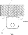
FIG. 3 andFIG. 4 are schematic diagrams of a working scenario of a cleaning robot according to an implementation of the present invention. -
FIG. 5 to FIG. 7 are schematic diagrams of a moving manner of a cleaning robot after recognizing a carpet according to an implementation of the present invention. -
FIG. 8 andFIG. 9 are schematic diagrams of a global map according to an implementation of the present invention. -
FIG. 10 is a schematic diagram in which a mopping assembly is lifted according to an implementation of the present invention. -
FIG. 11 is a flowchart of steps of a control method for a cleaning robot according to an implementation of the present invention. -
FIG. 12 is a flowchart of steps of a control method for a cleaning robot according to an implementation of the present invention. -
FIG. 13 is a schematic structural diagram of a cleaning robot according to another implementation of the present invention. -
FIG. 14 is a schematic diagram in which the cleaning robot in the implementation ofFIG. 13 recognizes a carpet. -
FIG. 15 is a schematic distribution diagram of a detection device on a forward direction side of the cleaning robot in the implementation ofFIG. 13 . - The technical solution of the present invention will be described in detail below with reference to the accompanying drawings and implementations. It should be understood that these implementations are only used to illustrate the present invention and not to limit the scope of the present invention. After reading the present invention, various equivalent modifications made by those skilled in the art to the present invention shall fall within the scope defined by the appended claims of this application.
- It should be noted that, when a component is referred to as "being disposed to" another component, the component may be directly on the another component, or there may be an intermediate component. When a component is considered to be "connected to" another component, the component may be directly connected to the another component, or there may be an intermediate component. The terms "vertical", "horizontal", "upper", "down", "left", "right" and similar expressions used in this specification are only for purposes of illustration but not indicate a unique implementation.
- Unless otherwise defined, meanings of all technical and scientific terms used in this specification are the same as those usually understood by a person skilled in the art to which this application belongs. In this application, terms used in the implementations of this application are merely intended to describe objectives of the specific implementations, but are not intended to limit this application. The term "and/or" used in this specification includes any and all combinations of one or more related listed items.
- Referring to
FIG. 1 to FIG. 4 , an implementation of this application provides acleaning robot 100. Thecleaning robot 100 may include: abody 1, amovable device 6, apositioning device 5, adetection device 3, a control device (not shown in the figure), and the like. Themovable device 6 includes a moving wheel disposed below thebody 1, a transmission mechanism in transmission connection with the moving wheel, and the like. Thecleaning robot 100 may further include a battery disposed in thebody 1. During use, electric energy provided by the battery is converted into mechanical energy by using the transmission mechanism and the mechanical energy is transferred to the moving wheel, to drive thecleaning robot 100 to move on a ground and perform cleaning work. - In this implementation, the
detection device 3 is configured to detect aground feature 44 in front of the cleaning robot. Specifically, thedetection device 3 can recognize whether a ground ahead is a carpet. Specifically, the detection device may be any one or a combination of the following: an ultrasonic sensor, an optical sensor (for example, an infrared sensor), a millimeter wave radar sensor, a mechanical switch, and the like. In this implementation, thedetection device 3 includes anultrasonic sensor 3a andmechanical switches body 1 includes a front portion and a rear portion in a forward direction. The ultrasonic sensor and the mechanical switches are all disposed on the front portion of the body and disposed at the bottom of the body, to effectively detect a carpet in the forward direction of the machine in time. A principle on which the ultrasonic sensor detects a carpet is similar to a conventional application in the art. The carpet is recognized by using the principle that transmitted signals have different reflection coefficients after being reflected by grounds with different roughness or received signals have different strengths. Details are not described herein again. The mechanical switches may detect the carpet through cooperation between a structural member and a switching device. For example, when encountering a carpet, the movable structural member moves under the action of an external force to trigger the switching device. The switching device includes a micro switch, a photoelectric switch, a Hall, a reed switch, or the like. Certainly, in another implementation, the detection device may be alternatively mounted on the rear portion of the body, or on another position such as a side portion, and can detect theground feature 44 ahead when the cleaning robot moves in different directions. - In this implementation, the
positioning device 5 may be disposed on thebody 1 and configured to obtain position information of the cleaning robot. Specifically, the positioning device may be a laser SLAM positioning device or a visual SLAM positioning device. A specific form of the positioning device may vary according to different working principles of the positioning device, which is not specifically limited in this application. - In this implementation, the control device may store or obtain a map of a working region of the cleaning robot (briefly referred to as a global map 4). Specifically, a manner of obtaining the global map by the cleaning robot provided with the positioning device may be implemented based on a current laser SLAM mapping technology or visual SLAM mapping technology or a combination of a laser SLAM mapping technology and a visual SLAM mapping technology. Certainly, the manner of obtaining the global map is not limited to the above example. For example, the manner may be further receiving data sent by an APP of a user terminal. This is not specifically limited in this application.
- In an implementation, the
global map 4 may be pre-established based on a signal detected by the positioning device before the cleaning robot works formally, and is stored in a storage unit of the control device. Certainly, theglobal map 4 may alternatively be synchronously established based on a signal detected by the positioning device during traveling and working of the cleaning robot. This is not specifically limited in this application. - As shown in
FIG. 8 andFIG. 9 , when the cleaning robot is specifically an indoor cleaning robot, theglobal map 4 may be an indoor floor layout plan of a user. Theglobal map 4 may include: a travelingregion 41 such as a living room, a bedroom, a bathroom, or a kitchen, and an entrance/exit region 42 for entering or leaving the travelingregion 41, where the entrance/exit region is usually a region in which a door is located. In addition, aboundary 43 of a non-entrance/exit region may be further disposed in theglobal map 4. Theboundary 43 of the non-entrance/exit region may vary according to different application environments. For example, for the indoor cleaning robot, theboundary 43 of the non-entrance/exit region may be a wall. The travelingregion 41 may be a region that may need to be cleaned by the cleaning robot. For the indoor cleaning robot, the travelingregion 41 may be a region other than the wall in a floor plan of the user. - Specifically, there may be at least two traveling
regions 41, which may include a first travelingregion 41 and a second travelingregion 41. The entrance/exit region 42 is disposed between the first travelingregion 41 and the second travelingregion 41. That is, the entrance/exit region 42 mainly refers to a junction of the two travelingregions 41. The entrance/exit region 42 may be determined by using a pattern of theglobal map 4 or may be designated by using an APP of the user. For the indoor cleaning robot, the entrance/exit region 42 mainly refers to a region of a door. - The cleaning robot further includes a cleaning device. In this implementation, the cleaning device includes a wiping and/or washing device. For example, when the cleaning robot is a mopping machine or a mopping, sweeping. and vacuuming integrated machine, the cleaning robot may be further provided with a mopping
assembly 2. The moppingassembly 2 may be fixed on thebody 1 by using a lifting device. The moppingassembly 2 may be designed to be mounted on/unloaded from the body without any tool. When a mopping function needs to be performed, the moppingassembly 2 may be lowered by using the lifting device until the mopping assembly is in contact with the ground. Specifically, a cleaning component, which mainly plays the mopping role, of the moppingassembly 2 may be in the form of a mop. Certainly, the moppingassembly 2 may be alternatively a sponge or in another specific form. This is not specifically limited in this application. - The control device is electrically connected to the
detection device 3 and thepositioning device 5, obtains signals obtained by signal obtaining elements such as thedetection device 3 and thepositioning device 5, and then sends corresponding control instructions based on the obtained signals and stored computer-executable instructions. - The control device can determine a position of the cleaning robot in the map according to position information of the cleaning robot. Specifically, the control device may perform multi-angle comparison on current position information of the cleaning robot obtained by the positioning device in the
global map 4 when labeling a position of the cleaning robot in the map, to accurately determine a current position of the cleaning robot in the map. - In this implementation, the control device recognizes a
ground feature 44 in front of the cleaning robot according to a detection result of thedetection device 3, and controls, according to the position of the cleaning robot in the map, the cleaning robot to perform a corresponding action. Specifically, the recognizing, by the control device, aground feature 44 in front of the cleaning robot according to a detection result of thedetection device 3 includes: recognizing whether theground feature 44 is a carpet. Correspondingly, the controlling, by the control device, the cleaning robot to perform a corresponding action includes: controlling the cleaning robot not to enter a region in which the carpet is located, or to pass through a region in which the carpet is located. - For example, in one case, when recognizing the ground feature as a carpet and when determining, according to the position information of the cleaning robot, that the cleaning robot is beyond a range of a first predetermined distance to the entrance/exit region, the control device controls the cleaning robot not to enter a region in which the carpet is located, to prevent the cleaning robot from contaminating the carpet.
- In one case, when recognizing the ground feature as the carpet and when determining, according to the position information of the cleaning robot, that the cleaning robot is within a range of a second predetermined distance to the entrance/exit region, the control device controls the cleaning robot to pass through the region in which the carpet is located, to avoid a case that after recognizing the carpet, the cleaning robot does not enter the region in which the carpet is located and is limited by a single traveling region, and as a result, the cleaning robot cannot move to different traveling regions to perform cleaning work within a global map range.
- In this implementation, the first predetermined distance may be between 50 cm and 100 cm. Specifically, a value range of the first predetermined distance may be determined according to an actual application scenario. For example, for a general user family, a carpet may be placed at a door, and a position of the carpet has a particular deviation range near the door. In this case, a region within the range of the first predetermined distance beyond the door may be set to a region in which the carpet may exist. When a carpet is recognized in the region, the cleaning robot passes through the region and enters a new traveling region.
- The range of the second predetermined distance may be determined according to an actual application scenario. For example, for a general user family, a carpet may be placed at a door, and a position of the carpet has a particular deviation range near the door. In this case, a region within the range of the second predetermined distance beyond the door may be set to a region in which the carpet may exist. When a carpet is recognized in the region, the cleaning robot passes through the region and enters a new traveling
region 41. - On the whole, the second predetermined distance may be the same as the first predetermined distance and may be between 50 cm and 100 cm. In addition, the second predetermined distance may be different from the first predetermined distance, for example, may be set according to an actual size of a doorway. This is not specifically limited in this application. In this implementation, there is an overlapping part between a part beyond the range of the first predetermined distance and a part within the range of the second predetermined distance.
- In this implementation, the controlling, by the control device, the cleaning robot not to enter a region in which the carpet is located includes: controlling the cleaning robot to drive away from the carpet, or controlling the cleaning robot to move along an edge of the carpet.
FIG. 5 to FIG. 7 are schematic diagrams of several movement manners of the cleaning robot when encountering a carpet. As shown inFIG. 5 , in one case, the cleaning robot moves along an edge of the carpet after encountering the carpet, to clean a region of the edge of the carpet, and after cleaning the edge of the carpet, the cleaning robot returns to a breakpoint position in which the carpet is detected and continues to move along a previous path (for example, a zigzag-shaped path). As shown inFIG. 6 , in one case, the cleaning robot drives away from the carpet after encountering the carpet, to avoid contaminating the carpet. Specifically, the cleaning robot turns back, for example, turns back along the zigzag-shaped path. As shown inFIG. 7 , in one case, the cleaning robot passes through the carpet after encountering the carpet and enters a next traveling region for cleaning, to complete cleaning work within a global map range. - In this implementation, the cleaning robot includes an intra-region movement mode and a cross-region movement mode. In the intra-region movement mode, the control device controls the cleaning robot to move in one traveling region and perform cleaning work. In the intra-region movement mode, when recognizing the ground feature as a carpet, the control device controls the cleaning robot not to enter a region in which the carpet is located. In the intra-region movement mode, when the cleaning robot detects a carpet, regardless of a distance between the cleaning robot and the entrance/exit region, the cleaning robot avoids the carpet to perform the cleaning work. Specifically, the cleaning robot may move along an edge of the carpet, or move back, or the like. In this way, the cleaning robot can remain in a traveling region to continuously perform the cleaning work, and complete the cleaning work of the traveling region.
- In the cross-region movement mode, the control device controls the cleaning robot to enter, from one traveling region, another traveling region through the entrance/exit region. In the cross-region movement mode, when recognizing the ground feature as the carpet and when determining, according to position information of the cleaning robot, that the cleaning robot is within a range of a second predetermined distance to the entrance/exit region, the control device controls the cleaning robot to pass through a region in which the carpet is located, to enter the another traveling region from the one traveling region. After completing cleaning work of a traveling region, the cleaning robot enters the cross-region movement mode. The cleaning robot moves to the entrance/exit region according to position information of the cleaning robot and based on the map and passes through the entrance/exit region, to enter another to-be- worked traveling region for working. When the cleaning robot detects a carpet and the cleaning robot is within the range of the second predetermined distance to the entrance/exit region, the cleaning robot passes through a region in which the carpet is located, to enter another traveling region. When the cleaning robot detects the carpet, but the cleaning robot is beyond the range of the first predetermined distance to the entrance/exit region, the cleaning robot does not enter the region in which the carpet is located. Specifically, the cleaning robot may bypass the carpet, to avoid contaminating the carpet. In this way, the cleaning robot can not only complete the cleaning work within the global map range, but also make the cleaning work achieve clean and efficient effects.
- Referring to
FIG. 10 , further, when the detection device detects the carpet, the control device can further control a mopping assembly lifting device to lift the moppingassembly 2, to avoid being in contact with the carpet. Especially when the cleaning robot needs to pass through the region in which the carpet is located and enter a next traveling region, the lifting device is controlled to lift the moppingassembly 2 to a position higher than the carpet, and then the cleaning robot passes through the carpet, to prevent a mop in the moppingassembly 2 from dirtying the carpet. - According to the cleaning robot provided in this implementation, the
ground feature 44 in front of the cleaning robot can be recognized according to a detection result of the detection device. In a traveling and working process, the cleaning robot can label a position in a map in real time by using position information obtained by a positioning device and the map of a working region of the cleaning robot, and perform a corresponding action according to the position labeled in the map, thereby achieving different functions, so that the degree of intelligence is high, and the usage reliability is high, thereby greatly improving comprehensive user experience. - Specifically, for different positions of the cleaning robot in the map, the following different control actions are adopted:
- 1. When the cleaning robot is near a non-entrance/exit region (door) and the detection device senses a carpet in a forward direction, the cleaning robot does not enter a front region, so that the carpet can be prevented from being dirtied.
- 2. When the cleaning robot is near an entrance/exit region (door) and the
detection device 3 senses a carpet in a forward direction, the moppingassembly 2 is lifted, and the cleaning robot enters a front region, so that the cleaning robot can move to different traveling regions and perform cleaning work within a global map range without being limited by a single traveling region, and the carpet is not dirtied. - As shown in
FIG. 11 , for the foregoing cleaning robot, this application further correspondingly provides a control method for a cleaning robot. Specifically, the control method for a cleaning robot may include the following steps. - Step S10. Obtain position information of the cleaning robot, and determine a position of the cleaning robot in the map according to the position information of the cleaning robot.
- Step S12. Recognize a
ground feature 44 in front of the cleaning robot according to a detection result of a detection device of the cleaning robot, and control, according to the position of the cleaning robot in the map, the cleaning robot to perform a corresponding action. - It should be noted that the control method for a cleaning robot may be applicable to different scenarios according to different ground features 44 ahead. In this implementation, a description is made by using carpet recognition as an example. Another form of the
ground feature 44 ahead may be adjusted adaptively according to a recognition method provided in this application. - In this implementation, for specific steps of the control method for a cleaning robot, reference may be made to the foregoing description. Details are not described herein again.
-
FIG. 12 is a flowchart of a control method for a cleaning robot according to this implementation. InFIG. 12 , for example, the first predetermined distance is the same as the second predetermined distance. - This application further provides a detection device for detecting a carpet and a corresponding method.
- Referring to
FIG. 13 to FIG. 15 , in an implementation, thedetection device 3 includes a ranging sensor, and the ranging sensor may be a time of flight (TOF) sensor or a triangular ranging sensor. The TOF sensor is briefly referred to as TOF, which mainly implements distance measurement by using a time of flight technology. A basic principle of the time of flight technology is that a light emitting element is loaded, and photons emitted by the light emitting element are reflected back after hitting a surface of an object. The photons emitted by the light emitting element and reflected from the surface of the object are captured by using a special CMOS sensor, and times of flight of the photons can be obtained. Distances of flight of the photons may be calculated according to the times of flight of the photons, that is, height (depth) information of the object is obtained. Thebody 1 may include a housing having afront surface 11 in a forward direction. Thedetection device 3 may be disposed on thefront surface 11. In this implementation, thedetection device 3 is disposed on thebody 1 and is configured to detect aground feature 44 in front of the cleaning robot. Theground feature 44 ahead may include a convex feature or a concave feature relative to a current ground on which the cleaning robot is located. When theground feature 44 ahead is the convex feature, correspondingly, thedetection device 3 is mainly configured to determine a height of a to-be-traveled region ahead, including a height of a ground without any object ahead and a height of an object when there is the object ahead. There may be onedetection device 3. When there is onedetection device 3, thedetection device 3 may be disposed in the middle of thefront surface 11. There may be alternatively two or threedetection devices 3. At least twodetection devices 3 are distributed on a side edge of thefront surface 11 and are at the same height. For example, when there are twodetection devices 3, the twodetection devices 3 are distributed on the side edge of thefront surface 11 and are at the same height. When there are threedetection devices 3, two of the threedetection devices 3 are distributed on the side edge of thefront surface 11, one detection device is located in the middle of thefront surface 11, and the threedetection devices 3 are at the same height. When at least twodetection devices 3 are disposed on the side edge of thefront surface 11, it can be ensured that the machine can recognize theground feature 44 ahead as soon as possible before entering theground feature 44 ahead from different angles. - In this implementation, the
detection device 3 has a detection direction. A range of an angle θ between the detection direction and a vertical direction is between 0 degrees and 90 degrees, to ensure that the cleaning robot may recognize theground feature 44 ahead in advance before entering theground feature 44 ahead, and then perform a corresponding control operation. - Theoretically, a mounting angle (an angle between the detection direction and a gravity direction) of the
detection device 3 may be any angle between 0 degrees and 360 degrees. To ensure that thedetection device 3 can detect theground feature 44 ahead, the angle θ between the detection direction of thedetection device 3 and the vertical direction needs to be between 0 degrees and 90 degrees. Preferably, the mounting angle of thedetection device 3 is consistent with the angle θ between the detection direction and the vertical direction, and is between 0 degrees and 90 degrees. When the mounting angle of thedetection device 3 is between 90 degrees and 360 degrees, a reflection structure may be added. That the angle θ between the detection direction of thedetection device 3 and the vertical direction needs to be between 0 degrees and 90 degrees is implemented through a light path reflection principle. - In addition, the mopping
assembly 2 is located behind thefront surface 11 in the forward direction. A distance between the mopping assembly and the front surface is h1 in the forward direction. Even when thedetection device 3 is mounted vertically and detects theground feature 44 ahead, the control device can still control in time the moppingassembly 2 to perform a lifting action or a braking action, so that the moppingassembly 2 is not in contact with theground feature 44 ahead. - The control device can label a reference height of a current traveling
region 41 and obtain a height parameter of thedetection device 3. - Specifically, the control device stores a computer-executable instruction. Based on an obtained signal and the stored computer-executable instruction, when a carpet is sensed by the
detection device 3, it indicates that there is aspecific ground feature 44 ahead. - Further, to improve the accuracy of the recognition of the
ground feature 44 ahead, thedetection device 3 senses, in the forward direction, a convexity of which a height exceeds a preset value, and detects that a length of the convexity exceeds a predetermined length, and it indicates that there is theground feature 44 ahead. When detecting the length of the convexity in the forward direction, thedetection device 3 may determine the length of the convexity according to a time of detecting the convexity of which the height exceeds the preset value in combination with a traveling speed of the cleaning robot, and then compare the determined length of the convexity with the predetermined length, to determine whether the detected length of the convexity exceeds the predetermined length. Certainly, thedetection device 3 can alternatively directly measure the length of the convexity in the forward direction, and subsequently compare the detected length of the convexity with the predetermined length, to determine whether the detected length of the convexity exceeds the predetermined length. Certainly, a manner of detecting the length of the convexity in the forward direction is not limited to the foregoing example. This is not specifically limited in this application. - In an implementation, the
detection device 3 obtains, by detecting a distance between the cleaning robot and the ground, a height parameter representing a height of the ground, and the control device recognizes theground feature 44 according to a result of comparison between the height parameter and a preset value. - In this implementation, the height parameter may include a height value or a distance value in the detection direction. When the height parameter is the height value, it may be specifically a height difference ΔH between the detected highest point of the
ground feature 44 ahead and a reference ground. When the height parameter is the distance value in the detection direction, it may be specifically a difference ΔL between a distance reference value L in the detection direction and an actually measured distance value L1. - ΔH=ΔL×COSθ. If a manner of comparing ΔH with a preset value is adopted, the preset value is specifically a preset height value, and when ΔH exceeds the preset height value, it indicates that the
ground feature 44 ahead is recognized. - In addition, if a manner of comparing ΔL with a preset value is adopted, the preset value is a preset distance value, and when ΔL exceeds the preset distance value, it indicates that the
ground feature 44 ahead is recognized. When the preset value is the preset distance value, thedetection device 3 may be obliquely disposed on thebody 1 at a particular angle to the vertical direction. - In the following implementations, a description is made mainly by using a height value as an example. For the distance value in the detection direction, reference may be made to the height value by analogy. Details are not described again in this application.
- Specifically, the preset value includes a first preset value. The
detection device 3 detects that a height value of the ground feature is greater than the first preset value, and the control device recognizes theground feature 44 ahead as a carpet. Generally, the ground in the room of the user is a ground type such as a floor or a tile with better flatness. When the cleaning robot is located in a travelingregion 41 in which theground feature 44 ahead is located, the first preset value may be determined according to a height of theground feature 44 ahead (or a size in a height direction). For example, when theground feature 44 ahead is a carpet, a thickness of the carpet is generally more than 5 mm, and the first preset value may be alternatively set to 5 mm. - In addition, the carpet generally has a particular size, and the size may be determined according to a shape and a position of the carpet. This is not specifically limited in this application. However, the size of the carpet has at least a predetermined length in a traveling direction of the cleaning robot. Therefore, the predetermined length may be stored in the control device, for example, the predetermined length may be 2 cm.
- When the cleaning robot provided in this implementation is in a mopping mode, the
detection device 3 senses a convexity of which a height exceeds the first preset value near the non-entrance/exit region (door) in the forward direction, and it indicates that theground feature 44 ahead (for example, the carpet) is recognized. Further, to improve the accuracy of the recognition of theground feature 44 ahead, thedetection device 3 senses, in the forward direction, the convexity of which the height exceeds the first preset value, and detects that a length of the convexity exceeds a predetermined length, and it indicates that there is theground feature 44 ahead. - The cleaning robot provided in this application recognizes the
ground feature 44 ahead mainly based on a physical size of theground feature 44 ahead. Compared with other recognition manners in the prior art, not only the recognition reliability is higher, but also no virtual forbidden region needs to be set, thereby greatly improving the user usage experience. - In addition, the cleaning robot provided in this application can further perform different actions correspondingly after recognizing the
ground feature 44 ahead in another position. - In another case, when a current to-be-traveled region is a concave region, the cleaning robot provided in this application has an anti-falling function.
- The preset value includes a second preset value. When the
detection device 3 detects that the height parameter of theground feature 44 is less than the second preset value, the control device recognizes theground feature 44 as a cliff and controls the cleaning robot not to enter a region in which the cliff is located. - In this implementation, the second preset value is mainly used for evaluating a degree of concavity of the current to-be-traveled region. Specifically, the second preset value may be a negative number less than 0. The second preset value may be specifically determined according to performance (for example, an obstacle crossing capability) of the cleaning robot. For example, the second preset value may be -15 cm, or certainly may be another value. This is not specifically limited in this application. When the height parameter is less than the second preset value, it indicates that the cleaning robot has the risk of failing to work normally after falling.
- In still another case, referring to the
global map 4, theglobal map 4 further includes aboundary 43 of a non-entrance/exit region. When it is recognized that a current position is within a third predetermined distance to theboundary 43, thedetection device 3 is shielded, and the cleaning robot is controlled to continue to work. - In this implementation, the
boundary 43 may be a wall, and a description is made below by using the wall as an example. The third predetermined distance may be 5 cm, and a specific value of the third predetermined distance is not limited to 5 cm. This is not specifically limited in this application. When the cleaning robot moves to a position within the third predetermined distance to the wall, thedetection device 3 is shielded, to avoid a case that the cleaning robot considers the wall as theground feature 44 ahead and does not continue to approach. After thedetection device 3 is shielded, the cleaning robot continues to move forward to clean a corner of the wall. - In this implementation, the
detection device 3 generally needs to calibrate a height parameter before working. - In this implementation, a reference height of a current traveling
region 41 may be calibrated before the cleaning robot is controlled to travel, and the height parameter of thedetection device 3 is obtained. Specifically, the obtained height parameter of thedetection device 3 is mainly used for providing a comparison reference for calculating a height of aground feature 44 ahead in the current travelingregion 41, and specifically for providing an initial calculation point for measuring a height of theground feature 44 ahead. - The height parameter may include a distance reference value L in the detection direction, or certainly, the height parameter may be a height reference value H in the vertical direction. During specific calibration, an example in which the height parameter is the distance reference value L is used, and when the cleaning robot is horizontally still at a reference surface, N groups of data may be obtained, and then an average value of the N groups of data may be used as the distance reference value L.
- A moment of the calibration may be set according to different application scenarios. For example, the cleaning robot may automatically perform calibration in a base station after each time of returning to the base station; or each time leaving a base station for working, the cleaning robot may first perform calibration near the base station and then work; or the cleaning robot first automatically performs calibration after startup; or the cleaning robot first performs calibration and then works after entering different regions in the map; or after the mopping
assembly 2 is replaced, or the moppingassembly 2 is lifted, or the cleaning robot gets out of trouble, the cleaning robot may perform calibration, to improve the accuracy of the detection. - In this implementation, when determining whether the
ground feature 44 ahead is a carpet, the control device subtracts the actually measured distance value L1 from the distance reference value L to obtain ΔL. - When ΔL>0, it indicates that the ground feature is a convexity relative to a reference ground, and a vertical distance of the convexity is ΔH=ΔL×COSθ.
- When ΔL<0, it indicates that the ground feature is a concavity relative to the reference ground, and a vertical distance of the concavity is ΔH=ΔL×COSθ.
- If the height of the convexity is greater than a preset value (for example, 5 mm), it indicates that the ground feature 44 (a carpet) ahead is recognized.
- When it is determined that the preset value is 5 mm preferably, it is mainly considered that actual heights of most carpets are greater than 5 mm and fluctuation of the ground in the home is less than the value, and meanwhile, a price-performance ratio of a current sensor is considered. If the height of the concavity is greater than an obstacle crossing height, the machine does not enter the concavity.
- The cleaning robot provided in this application recognizes the
ground feature 44 ahead mainly based on a physical size of theground feature 44 ahead. Therefore, compared with other recognition manners in the prior art, during use, the cleaning robot can reliably recognize ground features ahead including the carpet and no virtual forbidden region needs to be set. - When the cleaning robot is within a particular distance to the
boundary 43, thedetection device 3 is shielded, and the cleaning robot is controlled to continue to clean, so that the cleaning robot can clean a corner region of theboundary 43 without any dead angle. - When recognizing the
ground feature 44 ahead as a cliff, the cleaning robot may not enter a region in which the cliff is located, to prevent the cleaning robot from falling. - Further, for a case that the cleaning robot does not enter a front region, by controlling a mounting angle of the
detection device 3, theground feature 44 ahead may be recognized in advance by a particular distance, so that the cleaning robot can be more reliably prevented from entering the front region such as a carpet or a cliff that is not at the door. - Certainly, the cleaning robot provided in this implementation can not only recognize the
ground feature 44 ahead such as the carpet, but also adjust the first preset value and a value of the predetermined length according to actual requirements, to recognize aground feature 44 ahead with another size. Specifically, examples are not described again one by one in this application. - In this implementation, a reference height of a current traveling
region 41 may be calibrated before the cleaning robot is controlled to travel, and the height parameter of thedetection device 3 is obtained. Specifically, the obtained height parameter of thedetection device 3 is mainly used for providing a comparison reference for calculating a height of aground feature 44 ahead in the current travelingregion 41, and specifically for providing an initial calculation point for measuring a height of theground feature 44 ahead. - In this specification, the
detection device 3 obtains, by detecting a distance between the cleaning robot and theground feature 44 ahead, a height parameter representing a height of theground feature 44 ahead, and the control device recognizes theground feature 44 ahead according to a result of comparison between the height parameter and a preset value. Subsequently, the control device controls, according to a position of the cleaning robot labeled in the map, the cleaning robot to perform a corresponding action. - In this implementation, when the cleaning robot is beyond the range of the first predetermined distance to the entrance/
exit region 42, thedetection device 3 senses a convexity of which a height exceeds the first preset value in the forward direction, and it may indicate that theground feature 44 ahead is recognized as a carpet. - Further, to improve the accuracy of the recognition of the
ground feature 44 ahead, determining may be performed according to a consecutive distance of the convexity. Specifically, based on a case that it is sensed that the protrusion of which the height exceeds the first preset value, the length of the protrusion may be superimposed to exceed the first predetermined length, and it indicates that theground feature 44 ahead is recognized. - When the cleaning robot provided in this implementation is in a mopping mode, the
detection device 3 senses a convexity of which a height exceeds the first preset value (for example, 5 mm) near the non-entrance/exit region (door) in the forward direction, the consecutive distance of the convexity exceeds a predetermined length (for example, 2 cm), and it indicates that theground feature 44 ahead (for example, the carpet) is recognized. The cleaning robot provided in this application recognizes theground feature 44 ahead mainly based on a physical size of theground feature 44 ahead. Compared with other recognition manners in the prior art, during use, the cleaning robot can recognize the ground feature 44 (for example, the carpet) ahead, and the recognition reliability is higher; and moreover, no virtual forbidden region needs to be set, thereby greatly improving the user usage experience. - In another case, when determining, according to the position information of the cleaning robot, that the cleaning robot is within the range of the second predetermined distance to the entrance/exit region, the control device controls the cleaning robot to pass through the region in which the carpet is located.
- An example in which the entrance/
exit region 42 is mainly a door is used for description below. That is, when the cleaning robot detects a carpet near the door, the cleaning robot is controlled to pass through a region in which the carpet is located. - Specifically, the
detection device 3 detects that a height value of theground feature 44 is greater than a first preset value, and the control device recognizes theground feature 44 as the carpet. In this case, when determining, according to the position information of the cleaning robot, that the cleaning robot is within the range of the second predetermined distance to the entrance/exit region, the control device controls the cleaning robot to pass through the region in which the carpet is located. - For a junction of two traveling
regions 41, corresponding ground heights may be different. In this case, to avoid misjudgment of thedetection device 3 and to ensure that the cleaning robot can smoothly enter and leavedifferent traveling regions 41 to fully clean the working region, even if it is determined that there is theground feature 44 ahead within the range of the second predetermined distance to the entrance/exit region 42, the cleaning robot is still controlled to pass through a region in which theground feature 44 ahead is located. - The first preset value may be comprehensively determined according to a height of the
ground feature 44 ahead in combination with a current height parameter of thedetection device 3. Calculation is performed with a ground of a current region in which thedetection device 3 is located as a zero point, and the first preset value is less than or equal to the height of theground feature 44 ahead. Generally, the cleaning robot has an obstacle crossing height, which is calculated by using the ground of the current region in which thedetection device 3 is located as the zero point, and the first preset height is less than the highest obstacle crossing height of the cleaning robot. - Further, the control method for a cleaning robot may further include: lifting the mopping
assembly 2 when a convexity of which a height exceeds a preset value is sensed in a forward direction. The moppingassembly 2 may be specifically a mop, a sponge, or the like, or certainly, the mopping assembly is in another form. This is not specifically limited in this application. A description is made below by using the mop as an example. A lifted height of the mop is at least equal to a preset value, which helps to further perform a corresponding action according to an instruction of the control device. For example, when theground feature 44 ahead needs to be crossed, the moppingassembly 2 may be controlled to be lifted again, and then theground feature 44 ahead is passed through again. When theground feature 44 ahead needs to be avoided, the mop is lifted, which helps the cleaning robot to re-plan a moving route. In addition, in some special cases, for example, when the cleaning robot fails to brake or the route is planned incorrectly, direct contact between the mop and the carpet may be also avoided. - In an implementation, the
detection device 3 has a detection direction, a height parameter of thedetection device 3 includes a distance reference value L in the detection direction, and an angle between the detection direction and a vertical direction is θ. - A formula for calculating a height value ΔH of the
ground feature 44 is:
- For example, when the distance reference value L=50 mm, the actually measured distance value L1=38 mm, θ=38 degrees, and a preset value is 6 mm, ΔH=ΔL×COSθ=12×COS38°=9.5 mm.
- Because ΔH is greater than the preset value, it is determined that the ground feature 44 (a carpet) ahead is recognized.
- In an implementation, a range of the angle θ between the detection direction and the vertical direction is between 0 degrees and 90 degrees. In this implementation, to ensure that information about the ground ahead is predicted, the
detection device 3 may be optionally adetection device 3 that can be mounted in a non-vertical manner, for example, aTOF detection device 3. When thedetection device 3 is mounted obliquely downward as a whole, a detected distance may be advanced by a particular distance N. On the one hand, a braking distance can be ensured, and on the other hand, the wall can be effectively treated differently. For example, when N=5 cm, thedetection device 3 is shielded within 5 cm from the wall, to avoid incorrectly recognizing the wall as a carpet. - In an implementation, the cleaning robot further has an obstacle crossing function. Correspondingly, the control method for a cleaning robot may further include: controlling, when the
detection device 3 senses that there is a convexity or a concavity of which a height exceeds the highest obstacle crossing height in a current to-be-traveled region in the forward direction, the cleaning robot not to enter the to-be-traveled region ahead. The highest obstacle crossing height may be 15 mm. Certainly, according to different specific types and sizes of the cleaning robot, the highest obstacle crossing height may be adjusted according to actual requirements. This is not specifically limited in this application. - When the current to-be-traveled region is a concave region, the cleaning robot provided in this application has an anti-falling function.
- In a specific implementation, the preset value includes a second preset value. When the detection device detects that the height value of the
ground feature 44 is less than the second preset value, the control device recognizes theground feature 44 as a cliff and controls the cleaning robot not to enter a region in which the cliff is located. For the second preset value, reference may be made to the specific description of the cleaning robot in the foregoing implementation. Details are not described again in this application. - Referring to the
global map 4, theglobal map 4 further includes aboundary 43 of a non-entrance/exit region. The method further includes: when it is recognized that a current position is within a third predetermined distance close to theboundary 43, shielding thedetection device 3. - In this implementation, the
boundary 43 may be a wall, and a description is made below by using the wall as an example. The third predetermined distance may be 5 cm, and a specific value of the third predetermined distance is not limited to 5 cm. This is not specifically limited in this application. When the cleaning robot moves to the third predetermined distance close to the wall, thedetection device 3 is shielded, to avoid a case that the cleaning robot considers the wall as theground feature 44 ahead and does not continue to approach. After thedetection device 3 is shielded, the cleaning robot continues to move forward to clean a corner of the wall. - In a main application scenario, a mopping, sweeping, and vacuuming integrated cleaning robot has an automatic charging function, and a charging base station of the cleaning robot is generally disposed at a position away from a door. Therefore, when the cleaning robot works, an initial position is generally not near the door by default. After the cleaning robot is started, the
detection device 3 senses a convexity of which a height exceeds a preset value (for example, 5 mm) in a forward direction, a consecutive distance of the convexity exceeds a predetermined length (for example, 2 cm), and it indicates that aground feature 44 ahead (for example, a carpet) is recognized. The cleaning robot provided in this application recognizes theground feature 44 ahead mainly based on a physical size of theground feature 44 ahead. Compared with other recognition manners in the prior art, during use, the cleaning robot can recognize the carpet, and the recognition reliability is higher; and moreover, no virtual forbidden region needs to be set, thereby greatly improving the user usage experience. - It should be noted that, in the descriptions of this application, terms "first" and "second" are only used to describe the objective and distinguish similar objects without a limitation on a sequence between the two, and cannot be understood as indicating or implying relative importance. In addition, in the description of this application, unless otherwise stated, "a plurality of" means two or more than two.
- The foregoing implementations are all described in a progressive manner. For same or similar parts in the implementations, cross reference is made, and descriptions of each implementation focus on a difference from other implementations.
- The foregoing descriptions are merely several implementations of the present invention. Although the implementations disclosed in the present invention are described above, the content of the implementations is only used to facilitate the understanding of the present invention, and is not intended to limit the present invention. Any person skilled in the art of the present invention can make any modification and change in the form and details of the implementations without departing from the spirit and scope of the present invention. However, the protection scope of the present invention should still be subject to the scope defined by the appended claims.
Claims (22)
- A cleaning robot, comprising:a body;a movable device, disposed on the body and configured to drive the cleaning robot to move on a ground and perform cleaning work;a detection device, disposed on the body and configured to detect a ground feature in front of the cleaning robot;a positioning device, disposed on the body and configured to obtain position information of the cleaning robot; anda control device, electrically connected to the detection device and the positioning device, wherein the control device stores or obtains a map of a working region of the cleaning robot, and the control device is capable of determining a position of the cleaning robot in the map according to the position information of the cleaning robot; andthe control device is configured to recognize the ground feature according to a detection result of the detection device and control, according to the position of the cleaning robot in the map, the cleaning robot to perform a corresponding action.
- The cleaning robot according to claim 1, wherein the recognizing, by the control device, the ground feature according to a detection result of the detection device comprises: recognizing whether the ground feature is a carpet; and
the controlling, by the control device, the cleaning robot to perform a corresponding action comprises: controlling the cleaning robot not to enter a region in which the carpet is located, or to pass through a region in which the carpet is located. - The cleaning robot according to claim 2, wherein the detection device comprises at least one of the following: an ultrasonic sensor, an optical sensor, a millimeter wave radar sensor, and a mechanical switch.
- The cleaning robot according to claim 2, wherein the detection device comprises a ranging sensor, the detection device obtains, by detecting a distance between the cleaning robot and the ground, a height parameter representing a height of the ground, and the control device recognizes the ground feature as the carpet according to a case that the height parameter is greater than a first preset value.
- The cleaning robot according to claim 1, wherein the map comprises a traveling region and an entrance/exit region for entering or leaving the traveling region; and the control device is configured to control, when recognizing the ground feature as a carpet and when determining, according to the position information of the cleaning robot, that the cleaning robot is beyond a range of a first predetermined distance to the entrance/exit region, the cleaning robot not to enter a region in which the carpet is located.
- The cleaning robot according to claim 1, wherein the map comprises a traveling region and an entrance/exit region for entering or leaving the traveling region; and the control device is configured to control, when recognizing the ground feature as a carpet and when determining, according to the position information of the cleaning robot, that the cleaning robot is within a range of a second predetermined distance to the entrance/exit region, the cleaning robot to pass through a region in which the carpet is located.
- The cleaning robot according to claim 6, comprising a cross-region movement mode, wherein in the cross-region movement mode, the control device controls the cleaning robot to enter, from one traveling region, another traveling region through the entrance/exit region; and
the control device is configured to control, in the cross-region movement mode, when recognizing the ground feature as the carpet and when determining, according to the position information of the cleaning robot, that the cleaning robot is within the range of the second predetermined distance to the entrance/exit region, the cleaning robot to pass through the region in which the carpet is located, to enter the another traveling region from the one traveling region. - The cleaning robot according to claim 1, comprising an intra-region movement mode, wherein in the intra-region movement mode, the control device controls the cleaning robot to move in one traveling region and perform the cleaning work; and
the control device is configured to control, in the intra-region movement mode, when recognizing the ground feature as a carpet, the cleaning robot not to enter a region in which the carpet is located. - The cleaning robot according to claim 2 or 5 or 8, wherein, the controlling, by the control device, the cleaning robot not to enter a region in which the carpet is located comprises: controlling the cleaning robot to drive away from the carpet, or controlling the cleaning robot to move along an edge of the carpet.
- The cleaning robot according to claim 1, further comprising a mopping assembly disposed on a lower surface of the body and a mopping assembly lifting device configured to lift or lower the mopping assembly, wherein the control device is configured to control, when recognizing the ground feature as a carpet, the mopping assembly lifting device to lift the mopping assembly.
- The cleaning robot according to claim 1, wherein the positioning device is a laser SLAM positioning device or a visual SLAM positioning device.
- The cleaning robot according to claim 1, wherein the map is obtained by the positioning device or is received from a user terminal.
- The cleaning robot according to claim 1, wherein the detection device is disposed at the bottom of the body and disposed at a front portion of the body.
- A control method for a cleaning robot, wherein the cleaning robot moves on a ground and performs cleaning work; the cleaning robot comprises a positioning device, configured to obtain position information of the cleaning robot, and a detection device, configured to detect a ground feature in front of the cleaning robot; and the cleaning robot stores or is capable of obtaining a map of a working region of the cleaning robot, and the control method comprises:obtaining the position information of the cleaning robot, and determining a position of the cleaning robot in the map according to the position information of the cleaning robot; andrecognizing the ground feature in front of the cleaning robot according to a detection result of the detection device of the cleaning robot, and controlling, according to the position of the cleaning robot in the map, the cleaning robot to perform a corresponding action.
- The control method for a cleaning robot according to claim 14, wherein when the ground feature is recognized as a carpet, controlling, according to the position of the cleaning robot in the map, the cleaning robot not to enter a region in which the carpet is located, or to pass through a region in which the carpet is located.
- The control method for a cleaning robot according to claim 14, wherein the map comprises a traveling region and an entrance/exit region for entering or leaving the traveling region; and the control method comprises: when the ground feature is recognized as a carpet and when it is determined, according to the position information of the cleaning robot, that the cleaning robot is beyond a range of a first predetermined distance to the entrance/exit region, controlling the cleaning robot not to enter a region in which the carpet is located.
- The control method for a cleaning robot according to claim 14, wherein the map comprises a traveling region and an entrance/exit region for entering or leaving the traveling region; and the control method comprises: when the ground feature is recognized as a carpet and when it is determined, according to the position information of the cleaning robot, that the cleaning robot is within a range of a second predetermined distance to the entrance/exit region, controlling the cleaning robot to pass through a region in which the carpet is located.
- The control method for a cleaning robot according to claim 17, wherein the cleaning robot comprises a cross-region movement mode, and in the cross-region movement mode, the cleaning robot is controlled to enter, from one traveling region, another traveling region through the entrance/exit region; and
the control method comprises: in the cross-region movement mode, when the ground feature is recognized as the carpet and when it is determined, according to the position information of the cleaning robot, that the cleaning robot is within the range of the second predetermined distance to the entrance/exit region, controlling the cleaning robot to pass through the region in which the carpet is located, to enter the another traveling region from the one traveling region. - The control method for a cleaning robot according to claim 14, wherein the cleaning robot comprises an intra-region movement mode, and in the intra-region movement mode, the cleaning robot is controlled to move in one traveling region and perform the cleaning work; and
the control method comprises: in the intra-region movement mode, when the ground feature is recognized as a carpet, controlling the cleaning robot not to enter a region in which the carpet is located. - The control method for a cleaning robot according to claim 15 or 16 or 19, wherein the controlling the cleaning robot not to enter a region in which the carpet is located comprises: controlling the cleaning robot to drive away from the carpet, or controlling the cleaning robot to move along an edge of the carpet.
- The control method for a cleaning robot according to claim 14, wherein the cleaning robot further comprises a mopping assembly disposed on a lower surface of the body and a mopping assembly lifting device configured to lift or lower the mopping assembly, and the control method comprises: when the ground feature is recognized as a carpet, controlling the mopping assembly to be lifted.
- The control method for a cleaning robot according to claim 14, wherein the map is obtained by the positioning device or is received from a user terminal.
Applications Claiming Priority (2)
| Application Number | Priority Date | Filing Date | Title |
|---|---|---|---|
| CN201910788271.0A CN112493924B (en) | 2019-08-26 | 2019-08-26 | Cleaning robot and control method thereof |
| PCT/CN2020/111411 WO2021037065A1 (en) | 2019-08-26 | 2020-08-26 | Cleaning robot and control method therefor |
Publications (2)
| Publication Number | Publication Date |
|---|---|
| EP4023131A1 true EP4023131A1 (en) | 2022-07-06 |
| EP4023131A4 EP4023131A4 (en) | 2023-01-11 |
Family
ID=74684497
Family Applications (1)
| Application Number | Title | Priority Date | Filing Date |
|---|---|---|---|
| EP20857792.4A Withdrawn EP4023131A4 (en) | 2019-08-26 | 2020-08-26 | Cleaning robot and control method therefor |
Country Status (6)
| Country | Link |
|---|---|
| US (1) | US20220280009A1 (en) |
| EP (1) | EP4023131A4 (en) |
| JP (1) | JP2022547661A (en) |
| KR (1) | KR20220042410A (en) |
| CN (2) | CN112493924B (en) |
| WO (2) | WO2021036072A1 (en) |
Families Citing this family (12)
| Publication number | Priority date | Publication date | Assignee | Title |
|---|---|---|---|---|
| EP3968051A1 (en) * | 2020-09-15 | 2022-03-16 | Infineon Technologies AG | Guiding system for a robot, base station including such a guiding system, and method for guiding a robot |
| CN114355871A (en) * | 2020-09-30 | 2022-04-15 | 好样科技有限公司 | Self-walking device and control method thereof |
| USD989426S1 (en) * | 2021-01-20 | 2023-06-13 | Vorwerk & Co. Interholding Gmbh | Robot vacuum cleaner |
| CN113143118A (en) * | 2021-04-06 | 2021-07-23 | 美智纵横科技有限责任公司 | Cleaning robot, intelligent control method and device thereof, and storage medium |
| CN115328108A (en) * | 2021-04-23 | 2022-11-11 | 南京泉峰科技有限公司 | Intelligent mowing equipment and operation control method thereof |
| CN113608524B (en) * | 2021-06-16 | 2024-04-16 | 深圳甲壳虫智能有限公司 | Automatic walking device, control method thereof, control device and storage medium |
| CN113974506B (en) | 2021-09-23 | 2024-03-19 | 云鲸智能(深圳)有限公司 | Cleaning control method, device, cleaning robot and storage medium |
| WO2023104174A1 (en) * | 2021-12-08 | 2023-06-15 | 苏州宝时得电动工具有限公司 | Cleaning robot system, and cleaning robot and control method therefor |
| CN114795000B (en) * | 2022-03-28 | 2024-02-23 | 北京小米移动软件有限公司 | Control method and control device of cleaning equipment, electronic equipment and storage medium |
| CN114747980A (en) * | 2022-03-31 | 2022-07-15 | 苏州三六零机器人科技有限公司 | Method, device and equipment for determining water yield of sweeping robot and storage medium |
| CN115429161B (en) * | 2022-07-29 | 2023-09-29 | 云鲸智能(深圳)有限公司 | Control method, device and system of cleaning robot and storage medium |
| CN117311367B (en) * | 2023-11-23 | 2024-04-19 | 科沃斯家用机器人有限公司 | Control method and control unit of self-mobile device and self-mobile device |
Family Cites Families (36)
| Publication number | Priority date | Publication date | Assignee | Title |
|---|---|---|---|---|
| JPH0947413A (en) * | 1995-08-08 | 1997-02-18 | Minolta Co Ltd | Cleaning robot |
| US8412377B2 (en) * | 2000-01-24 | 2013-04-02 | Irobot Corporation | Obstacle following sensor scheme for a mobile robot |
| KR101752190B1 (en) * | 2010-11-24 | 2017-06-30 | 삼성전자주식회사 | Robot cleaner and method for controlling the same |
| DE102012108802A1 (en) * | 2012-09-19 | 2014-03-20 | Vorwerk & Co. Interholding Gmbh | Automatically movable floor cleaning device and method for operating a floor cleaning device |
| KR102158695B1 (en) * | 2014-02-12 | 2020-10-23 | 엘지전자 주식회사 | robot cleaner and a control method of the same |
| CN104972462B (en) * | 2014-04-14 | 2017-04-19 | 科沃斯机器人股份有限公司 | Obstacle avoidance walking method of self-moving robot |
| US9798328B2 (en) * | 2014-10-10 | 2017-10-24 | Irobot Corporation | Mobile robot area cleaning |
| CN104526699B (en) * | 2014-12-05 | 2016-03-02 | 网易(杭州)网络有限公司 | Indoor cleaning machine people |
| CN106998980B (en) * | 2014-12-10 | 2021-12-17 | 伊莱克斯公司 | Floor type detection using laser sensors |
| CN106137057B (en) * | 2015-04-15 | 2018-10-19 | 小米科技有限责任公司 | Clean robot and robot collision-proof method |
| JP7058067B2 (en) * | 2016-02-16 | 2022-04-21 | 東芝ライフスタイル株式会社 | Autonomous vehicle |
| CN106272420B (en) * | 2016-08-30 | 2019-07-02 | 北京小米移动软件有限公司 | Robot and robot control method |
| CN107788913A (en) * | 2016-08-31 | 2018-03-13 | 科沃斯机器人股份有限公司 | Clean robot and its control method |
| CN206403708U (en) * | 2016-08-31 | 2017-08-15 | 科沃斯机器人股份有限公司 | Clean robot |
| CN106527449A (en) * | 2016-12-23 | 2017-03-22 | 上海木爷机器人技术有限公司 | Obstacle-avoidance system |
| CN106859512A (en) * | 2017-02-22 | 2017-06-20 | 深圳市软晶科技有限公司 | A kind of cleaning robot system of automatic replacing mop |
| US10610076B2 (en) * | 2017-06-23 | 2020-04-07 | Rug Doctor, LLC | Liquid extraction apparatus |
| US10551843B2 (en) * | 2017-07-11 | 2020-02-04 | Neato Robotics, Inc. | Surface type detection for robotic cleaning device |
| CN107280590B (en) * | 2017-08-03 | 2020-10-27 | 安徽省行千里知识产权服务有限公司 | Household cleaning device and cleaning method |
| CN108789430B (en) * | 2017-08-17 | 2021-10-01 | 烟台华腾技术有限公司 | Walking mechanism of intelligence robot of sweeping floor |
| CN107456162A (en) * | 2017-09-01 | 2017-12-12 | 苏州爱普电器有限公司 | Robot for cleaning floor and the control method for robot for cleaning floor |
| CN107440891B (en) * | 2017-09-11 | 2020-04-28 | 西安智财全技术转移中心有限公司 | Intelligent sharing blind-guiding robot based on data analysis |
| JP2019171001A (en) * | 2017-09-29 | 2019-10-10 | パナソニックIpマネジメント株式会社 | Autonomous mobile cleaner, cleaning method and program |
| DE102017126414A1 (en) * | 2017-11-10 | 2019-05-16 | Vorwerk & Co. Interholding Gmbh | Moist cleaning device for cleaning a surface |
| CN107635342A (en) * | 2017-11-15 | 2018-01-26 | 长沙翼希网络科技有限公司 | A kind of roam lamp control device and method |
| US10878294B2 (en) * | 2018-01-05 | 2020-12-29 | Irobot Corporation | Mobile cleaning robot artificial intelligence for situational awareness |
| CN108514381A (en) * | 2018-03-14 | 2018-09-11 | 深圳市沃特沃德股份有限公司 | Method, apparatus of sweeping the floor and sweeping robot |
| CN208892436U (en) * | 2018-05-10 | 2019-05-24 | 广东宝乐机器人股份有限公司 | A kind of clean robot |
| CN108888187A (en) * | 2018-05-31 | 2018-11-27 | 四川斐讯信息技术有限公司 | A kind of sweeping robot based on depth camera |
| CN108814437A (en) * | 2018-06-13 | 2018-11-16 | 芜湖金智王机械设备有限公司 | Sweeper control method and control system |
| CN108436921B (en) * | 2018-06-14 | 2020-04-24 | 广东盈科机器人产业有限公司 | Intelligent control method for sweeping robot |
| CN109358623A (en) * | 2018-10-23 | 2019-02-19 | 珠海市微半导体有限公司 | A kind of recognition methods, chip and the clean robot of the offset of robot motion's carpet |
| CN109846427A (en) * | 2019-01-16 | 2019-06-07 | 深圳乐动机器人有限公司 | A kind of control method and clean robot of clean robot |
| CN109602341B (en) * | 2019-01-23 | 2020-09-15 | 珠海市一微半导体有限公司 | Cleaning robot falling control method and chip based on virtual boundary |
| CN109984688A (en) * | 2019-04-18 | 2019-07-09 | 深圳乐行天下科技有限公司 | A kind of clean method in Robot side and robot |
| KR102305206B1 (en) * | 2019-07-11 | 2021-09-28 | 엘지전자 주식회사 | Robot cleaner for cleaning in consideration of floor state through artificial intelligence and operating method thereof |
-
2019
- 2019-08-26 CN CN201910788271.0A patent/CN112493924B/en active Active
- 2019-12-03 WO PCT/CN2019/122612 patent/WO2021036072A1/en active Application Filing
-
2020
- 2020-08-26 JP JP2022513138A patent/JP2022547661A/en active Pending
- 2020-08-26 CN CN202080059820.1A patent/CN114641229A/en active Pending
- 2020-08-26 WO PCT/CN2020/111411 patent/WO2021037065A1/en unknown
- 2020-08-26 KR KR1020227006604A patent/KR20220042410A/en not_active Application Discontinuation
- 2020-08-26 EP EP20857792.4A patent/EP4023131A4/en not_active Withdrawn
- 2020-08-26 US US17/638,795 patent/US20220280009A1/en active Pending
Also Published As
| Publication number | Publication date |
|---|---|
| JP2022547661A (en) | 2022-11-15 |
| CN114641229A (en) | 2022-06-17 |
| CN112493924A (en) | 2021-03-16 |
| KR20220042410A (en) | 2022-04-05 |
| CN112493924B (en) | 2023-03-10 |
| US20220280009A1 (en) | 2022-09-08 |
| EP4023131A4 (en) | 2023-01-11 |
| WO2021037065A1 (en) | 2021-03-04 |
| WO2021036072A1 (en) | 2021-03-04 |
Similar Documents
| Publication | Publication Date | Title |
|---|---|---|
| EP4023131A1 (en) | Cleaning robot and control method therefor | |
| EP3185096B1 (en) | A charging pile, method and device for recognizing the charging pile, and an autonomous cleaning device | |
| US9474427B2 (en) | Robot cleaner and method for controlling the same | |
| EP3084539B1 (en) | Prioritizing cleaning areas | |
| US8761939B2 (en) | Robot system and control method thereof | |
| CN214484411U (en) | Autonomous floor cleaner | |
| JP7206171B2 (en) | Navigation of autonomous mobile robots | |
| JP7243967B2 (en) | Method for Detecting Level Differences on a Surface in Front of a Robotic Cleaning Device | |
| CN110269547A (en) | Self-movement robot and its avoidance processing method | |
| CN113841098A (en) | Detecting objects using line arrays | |
| CN113545715A (en) | Control method and device of mopping robot and mopping robot | |
| KR20090053983A (en) | While moving of the travelling robot the robot cleaner which equips fully a discrimination of obstacle element and automatic charging equipment and analysis and evasion method | |
| CN212489787U (en) | Mopping robot | |
| CN113693501A (en) | Cleaning equipment, cleaning path, cleaning map generation method and cleaning map generation system | |
| AU2022328933A1 (en) | Cleaning robot, control method and apparatus therefor, and electronic device and storage medium | |
| CN208864213U (en) | Self-movement robot | |
| CN116250778A (en) | Cleaning control method and system of cleaning robot and cleaning robot | |
| CN114779777A (en) | Sensor control method and device for self-moving robot, medium and robot | |
| CN112882472A (en) | Autonomous mobile device | |
| CN217723394U (en) | Intelligent floor sweeping robot for route collaborative planning | |
| CN114431783B (en) | Cleaning robot and control method thereof | |
| CN111624989B (en) | Control method and self-mobile device | |
| WO2024087785A1 (en) | Operation area surface detection apparatus and cleaning robot | |
| CN117502976A (en) | Self-moving cleaning device and control method thereof |
Legal Events
| Date | Code | Title | Description |
|---|---|---|---|
| STAA | Information on the status of an ep patent application or granted ep patent |
Free format text: STATUS: THE INTERNATIONAL PUBLICATION HAS BEEN MADE |
|
| PUAI | Public reference made under article 153(3) epc to a published international application that has entered the european phase |
Free format text: ORIGINAL CODE: 0009012 |
|
| STAA | Information on the status of an ep patent application or granted ep patent |
Free format text: STATUS: REQUEST FOR EXAMINATION WAS MADE |
|
| 17P | Request for examination filed |
Effective date: 20220317 |
|
| AK | Designated contracting states |
Kind code of ref document: A1 Designated state(s): AL AT BE BG CH CY CZ DE DK EE ES FI FR GB GR HR HU IE IS IT LI LT LU LV MC MK MT NL NO PL PT RO RS SE SI SK SM TR |
|
| DAV | Request for validation of the european patent (deleted) | ||
| DAX | Request for extension of the european patent (deleted) | ||
| A4 | Supplementary search report drawn up and despatched |
Effective date: 20221209 |
|
| RIC1 | Information provided on ipc code assigned before grant |
Ipc: A47L 11/24 20060101AFI20221205BHEP |
|
| STAA | Information on the status of an ep patent application or granted ep patent |
Free format text: STATUS: THE APPLICATION HAS BEEN WITHDRAWN |
|
| P01 | Opt-out of the competence of the unified patent court (upc) registered |
Effective date: 20240312 |
|
| 18W | Application withdrawn |
Effective date: 20240315 |