EP4023088A1 - Program, method, and system for checking suction method of flavor suction instrument, etc - Google Patents
Program, method, and system for checking suction method of flavor suction instrument, etc Download PDFInfo
- Publication number
- EP4023088A1 EP4023088A1 EP19943619.7A EP19943619A EP4023088A1 EP 4023088 A1 EP4023088 A1 EP 4023088A1 EP 19943619 A EP19943619 A EP 19943619A EP 4023088 A1 EP4023088 A1 EP 4023088A1
- Authority
- EP
- European Patent Office
- Prior art keywords
- time
- predetermined change
- inhalation
- predetermined
- flavor
- Prior art date
- Legal status (The legal status is an assumption and is not a legal conclusion. Google has not performed a legal analysis and makes no representation as to the accuracy of the status listed.)
- Pending
Links
Images











Classifications
-
- A—HUMAN NECESSITIES
- A24—TOBACCO; CIGARS; CIGARETTES; SIMULATED SMOKING DEVICES; SMOKERS' REQUISITES
- A24F—SMOKERS' REQUISITES; MATCH BOXES; SIMULATED SMOKING DEVICES
- A24F40/00—Electrically operated smoking devices; Component parts thereof; Manufacture thereof; Maintenance or testing thereof; Charging means specially adapted therefor
- A24F40/50—Control or monitoring
- A24F40/53—Monitoring, e.g. fault detection
-
- A—HUMAN NECESSITIES
- A24—TOBACCO; CIGARS; CIGARETTES; SIMULATED SMOKING DEVICES; SMOKERS' REQUISITES
- A24F—SMOKERS' REQUISITES; MATCH BOXES; SIMULATED SMOKING DEVICES
- A24F40/00—Electrically operated smoking devices; Component parts thereof; Manufacture thereof; Maintenance or testing thereof; Charging means specially adapted therefor
- A24F40/60—Devices with integrated user interfaces
-
- G—PHYSICS
- G09—EDUCATION; CRYPTOGRAPHY; DISPLAY; ADVERTISING; SEALS
- G09G—ARRANGEMENTS OR CIRCUITS FOR CONTROL OF INDICATING DEVICES USING STATIC MEANS TO PRESENT VARIABLE INFORMATION
- G09G5/00—Control arrangements or circuits for visual indicators common to cathode-ray tube indicators and other visual indicators
- G09G5/02—Control arrangements or circuits for visual indicators common to cathode-ray tube indicators and other visual indicators characterised by the way in which colour is displayed
- G09G5/026—Control of mixing and/or overlay of colours in general
-
- A—HUMAN NECESSITIES
- A24—TOBACCO; CIGARS; CIGARETTES; SIMULATED SMOKING DEVICES; SMOKERS' REQUISITES
- A24F—SMOKERS' REQUISITES; MATCH BOXES; SIMULATED SMOKING DEVICES
- A24F40/00—Electrically operated smoking devices; Component parts thereof; Manufacture thereof; Maintenance or testing thereof; Charging means specially adapted therefor
- A24F40/50—Control or monitoring
- A24F40/51—Arrangement of sensors
-
- G—PHYSICS
- G09—EDUCATION; CRYPTOGRAPHY; DISPLAY; ADVERTISING; SEALS
- G09G—ARRANGEMENTS OR CIRCUITS FOR CONTROL OF INDICATING DEVICES USING STATIC MEANS TO PRESENT VARIABLE INFORMATION
- G09G2354/00—Aspects of interface with display user
-
- G—PHYSICS
- G09—EDUCATION; CRYPTOGRAPHY; DISPLAY; ADVERTISING; SEALS
- G09G—ARRANGEMENTS OR CIRCUITS FOR CONTROL OF INDICATING DEVICES USING STATIC MEANS TO PRESENT VARIABLE INFORMATION
- G09G2370/00—Aspects of data communication
- G09G2370/02—Networking aspects
- G09G2370/022—Centralised management of display operation, e.g. in a server instead of locally
-
- G—PHYSICS
- G09—EDUCATION; CRYPTOGRAPHY; DISPLAY; ADVERTISING; SEALS
- G09G—ARRANGEMENTS OR CIRCUITS FOR CONTROL OF INDICATING DEVICES USING STATIC MEANS TO PRESENT VARIABLE INFORMATION
- G09G2380/00—Specific applications
- G09G2380/06—Remotely controlled electronic signs other than labels
Definitions
- the present invention relates to a flavor inhalation device, or an aerosol generating device.
- the present invention relates to checking of a way of inhalation through a flavor inhalation device or an aerosol generating device.
- the way of inhalation through a smoking device has not been established.
- the way of inhalation varies by individual. Accordingly, a user's way of inhalation is cannot be regarded suitable for this user in some cases.
- the way of inhalation is described by text, and in addition, the way of another person's inhalation is represented by illustration, a video, etc.
- flavor inhalation device is a device for inhaling a flavor.
- the device encompasses, for example, electronic cigarettes, heated tobacco products, and conventional tobacco products.
- aerosol generating device is a device for inhaling generated aerosols.
- the device encompasses, for example, electronic cigarettes, heated tobacco products, and medical nebulizers.
- the invention described above uses an externally observable predetermined change that is caused based on the user's inhalation action and is caused at at least part of the flavor inhalation device or the like.
- the inventor of this application has realized that with some flavor inhalation devices and the like, the user's inhalation time period deviates from a time period in which the externally observable predetermined change occurs. For example, it has been found that with a certain flavor inhalation device, according to the specifications, upon detection of the start of the user's inhalation action, an externally observable predetermined change is simultaneously started, while after detection of completion of the user's inhalation action, the externally observable predetermined change is not immediately finished. If the user's inhalation action is detected simply by using the predetermined change at such a flavor inhalation device or the like, the detection result is different from the user's experience.
- the present invention has been made in view of the above description, and has an object to provide an improved program and the like for allowing the user to check the way of inhalation through a flavor inhalation device and the like while having an experience.
- An embodiment of the present invention provides a program causing a computer to execute: detecting an externally observable predetermined change caused at at least part of a flavor inhalation device or an aerosol generating device, the predetermined change being caused based on a user's inhalation action through the flavor inhalation device or the aerosol generating device; and displaying information, based on detection of the predetermined change, wherein said displaying information based on detection of the predetermined change includes controlling a showing of the information based on a difference between a time period during which the user's inhalation action is detected through the flavor inhalation device or the aerosol generating device, and a time period during which the predetermined change is caused.
- the difference may include a first predetermined time from detection of a finish of the user's inhalation action through the flavor inhalation device or the aerosol generating device to a finish of the predetermined change.
- said displaying information based on detection of the predetermined change may further include; displaying one or more pieces of information representing a time so as to indicate a lapse of time in a case where the predetermined change is detected, and said controlling the showing of information may include returning at least one of the one or more pieces of information representing the time to a display at the first predetermined time before, upon detection of the finish of the predetermined change.
- said displaying information based on detection of the predetermined change may further include: displaying one or more pieces of first information representing a time so as to indicate a lapse of time in a case where the predetermined change is detected, and wherein said controlling the showing of information may include displaying one or more pieces of second information representing a time obtained by subtracting the first predetermined time from the time represented by the one or more pieces of first information, upon detection of the finish of the predetermined change.
- said controlling the showing of information may include: displaying one or more pieces of information representing a time so as to indicate a lapse of time in a case where the predetermined change has been detected for the first predetermined time or longer.
- Such a configuration can provide the user with information for checking the way of inhalation in conformity with the experience.
- the difference may include a second predetermined time from detection of a start of the user's inhalation action through the flavor inhalation device or the aerosol generating device to a start of the predetermined change.
- said controlling the showing of information may include displaying, in a case where the predetermined change is detected, one or more pieces of information representing a time so as to indicate a lapse of time and as if the start of the predetermined change would have been detected the second predetermined time before from actual detection of the start of the predetermined change.
- Such a configuration can provide the user with information for checking the way of inhalation in conformity with the experience.
- the one or more pieces of information representing the time may include a character and a gauge, and said at least one of the one or more pieces of information representing the time may include the gauge.
- the one or more pieces of first information representing the time may include a gauge, and the one or more pieces of second information representing the time may include a character.
- the one or more pieces of information representing the time may include a character and/or a gauge.
- Such a configuration can provide the user with easily understandable information for checking the way of inhalation.
- An embodiment of the present invention provides a computer-implemented method including: detecting an externally observable predetermined change caused at at least part of a flavor inhalation device or an aerosol generating device, the predetermined change being caused based on a user's inhalation action through the flavor inhalation device or the aerosol generating device; and displaying information based on detection of the predetermined change, wherein said displaying information based on detection of the predetermined change includes controlling a showing of the information based on a difference between a time period during which the user's inhalation action is detected through the flavor inhalation device or the aerosol generating device, and a time period during which the predetermined change is caused.
- an embodiment of the present invention provides a system comprising: a detector; a display; and a controller configured to detect an externally observable predetermined change caused at at least part of a flavor inhalation device or an aerosol generating device based on an output from the detector, the predetermined change being caused based on a user's inhalation action through the flavor inhalation device or the aerosol generating device, and display on the display, information based on detection of the predetermined change, wherein the controller is further configured to control a showing of the information, based on a difference between a time period during which the user's inhalation action is detected through the flavor inhalation device or the aerosol generating device, and a time period during which the predetermined change is caused.
- An embodiment of the present invention provides a program causing a computer to execute: displaying a real-time image obtained, and a frame in the real-time image, the frame conforming to a shape of a flavor inhalation device or an aerosol generating device; detecting an externally observable predetermined change caused at at least part of the flavor inhalation device or the aerosol generating device, based on an image at a predetermined position or in a predetermined range in the real-time image, the predetermined change being caused based on a user's inhalation action through the flavor inhalation device or the aerosol generating device; and displaying information based on detection of the predetermined change.
- the predetermined position or the predetermined range may be in the frame.
- the predetermined position or the predetermined range may be out of the frame.
- the user can easily position the flavor inhalation device or the like in order to detect the predetermined change in the flavor inhalation device or the like.
- the limited portion in the real-time image is used to detect the predetermined change in the flavor inhalation device or the like, thereby improving the accuracy of detecting the predetermined change in the flavor inhalation device or the like having a confusing design from the predetermined change.
- the program according to one embodiment may further causing the computer to execute: determining whether the flavor inhalation device or the aerosol generating device overlaps the frame, based on the real-time image in the frame; and executing said detecting an externally observable predetermined change caused at at least part of the flavor inhalation device or the aerosol generating device, upon determination that the flavor inhalation device or the aerosol generating device overlaps the frame.
- the limited portion in the real-time image is used to detect the predetermined change in the flavor inhalation device or the like, thereby further improving the accuracy of detecting the predetermined change in the flavor inhalation device or the like having a confusing design from the predetermined change.
- An embodiment of the present invention provides a computer-implemented method including: displaying a real-time image obtained, and a frame in the real-time image, the frame conforming to a shape of a flavor inhalation device or an aerosol generating device; detecting an externally observable predetermined change caused at at least part of the flavor inhalation device or the aerosol generating device, based on an image at a predetermined position or in a predetermined range in the real-time image, the predetermined change being caused based on a user's inhalation action through the flavor inhalation device or the aerosol generating device; and displaying information, based on detection of the predetermined change.
- an embodiment of the present invention provides a system comprising: a detector; a display; and a controller configured to display, on the display, a real-time image and a frame in the real-time image, the real-time image obtained by the detector, and the frame conforming to a shape of a flavor inhalation device or an aerosol generating device; detect an externally observable predetermined change caused at at least part of the flavor inhalation device or the aerosol generating device, based on an image at a predetermined position or in a predetermined range in the real-time image, the predetermined change being caused based on a user's inhalation action through the flavor inhalation device or the aerosol generating device; and display, on the display, information based on detection of the predetermined change.
- the user can easily position the flavor inhalation device or the like in order to detect the predetermined change in the flavor inhalation device or the like.
- the limited portion in the real-time image is used to detect the predetermined change in the flavor inhalation device or the like, thereby improving the accuracy of detecting the predetermined change in the flavor inhalation device or the like having a confusing design from the predetermined change.
- the present invention allows the user to check the way of inhalation through a flavor inhalation device and the like while having an experience.
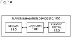
- Fig. 1A is a block diagram of an example configuration of a flavor inhalation device 100 or the like according to one embodiment of the present invention.
- Fig. 1A schematically and conceptually shows each of components included in the flavor inhalation device 100 or the like. It should be noted that the diagram does not show the strict arrangements, shapes dimensions, positional relationships and the like of the components and the flavor inhalation device 100 or the like.
- the flavor inhalation device 100 or the like can include components, not shown, for example, a tobacco capsule, a liquid cartridge, etc.
- Reference numeral 110 denotes a sensor for detecting the user's inhalation action.
- the sensor 110 may be any sensor for detecting the user's inhalation action; for example, the sensor may be a flow rate sensor, a flow velocity sensor, a pressure sensor, etc.
- the sensor 110 may be a button that the user presses to perform an inhalation action.
- the sensor 110 may be, for example, an inhalation sensor, and detect the user's inhalation through the flavor inhalation device 100 or the like.
- the sensor 110 may be an airflow sensor, and detect an airflow caused by user's inhalation.
- Reference numeral 120 denotes a changing part where an externally observable predetermined change occurs.
- the changing part 120 may be an LED (Light Emitting Diode) that emits light with a predetermined color, for example, a blue LED.
- the predetermined change may be emission of light with a predetermined color, e.g., blue. Note that the predetermined color is not limited to blue. Any color may be adopted.
- the predetermined change may be change in color of emitted light or change in emitted light intensity dependent on the strength of inhalation; the change is detected by the sensor 110.
- the changing part 120 is not limited to an LED, and may be a light source that has another configuration and emit light with the predetermined color.
- Fig. 1B shows a schematic appearance of an example of the flavor inhalation device 100 or the like.
- the flavor inhalation device 100 or the like has a stick shape that includes two ends 161 and 162 in some cases.
- the user holds one end 161 in the mouth for inhalation.
- the user may hold the one end 161 in the mouth via a mouthpiece attachable to the end 161.
- the changing part 120 is provided at the other end 162 between the two ends described above, and has a substantially rectangular shape.
- Fig. 1C shows a schematic appearance of another example of the flavor inhalation device 100 or the like.
- the differences of the flavor inhalation device 100 or the like shown in Fig. 1C from that shown in Fig. 1B are the position and the shape of the changing part 120. That is, in the flavor inhalation device 100 or the like shown in Fig. 1C , the changing part 120 is provided at a substantially intermediate portion between the end 161 and the end 162, and has an annular shape.
- the changing part 120 is at least part of the external surface of the flavor inhalation device 100 or the like, and may be, for example, a substantially rectangular shape or an annular shape as represented in Figs. 1B and 1C , or alternatively any shape, such as an annular shape (not shown) along the periphery of the flavor inhalation device 100 or the like.
- Reference numeral 121 in Figs. 1B and 1C denotes a design that is applied to the flavor inhalation device 100 or the like and is confusing from a predetermined change.
- the design 121 can be, for example, a pattern with the predetermined color in a case where the predetermined change is emission of light with a predetermined color.
- the design 121 is close to the changing part 120, but the design 121 may reside at any portion of the flavor inhalation device 100 or the like in some cases. Any shape of the design 121 can be adopted.
- One or more inconsecutive designs 121 may reside in some cases. Note that the flavor inhalation device 100 or the like may have no design 121 in some cases.
- reference numeral 130 denotes a controller that detects inhalation by the user through the flavor inhalation device 100 or the like at least on the basis of a signal from the sensor 110, and allows the changing part 120 to cause a predetermined change upon detection of the inhalation.
- the controller 130 may detect inhalation by the user through the flavor inhalation device 100 or the like on the basis of a fact that the strength of inhalation determined based on the intensity of the signal from the sensor 110 or on the signal (hereinafter, called "sensor signal etc.”), and upon detection of the inhalation, the controller may cause emission of light with the predetermined color at the changing part 120.
- the controller 130 may change the color of light emission or the intensity of light emission, dependent on the strength of inhalation determined based on the intensity of the signal from the sensor or the on the signal. For example, the controller 130 may increase the intensity of light emission when the inhalation is strong, and reduce the intensity of light emission at the changing part 120 when the inhalation is weak. For example, the controller 130 may classify the strength of inhalation into multiple stages, assign the multiple stages predetermined colors, respectively, and emit the light of the predetermined color associated with the strength of inhalation. Note that the controller 130 can detect the finish of inhalation by the user through the flavor inhalation device 100 or the like. Upon detection of the finish of inhalation, the controller can finish the predetermined change at the changing part 120.
- the controller 130 may detect the finish of inhalation by the user through the flavor inhalation device 100 or the like, based on a fact that the sensor signal or the like becomes equal to or less than a predetermined threshold. Upon detection of the finish of inhalation, the controller may finish the predetermined change at the changing part 120.
- the controller 130 may be an electronic circuit module configured as a microprocessor or a microcomputer.
- the time period during which the user is inhaling through the flavor inhalation device 100 or the like should coincide with the time period during which the predetermined change is caused.
- the former time period is sometimes different from the latter time period in actuality.
- a delay may be present between determination that the inhalation by the user is started, and a start of the predetermined change.
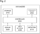
- Fig. 2 is a block diagram of an example configuration of a system 200 according to one embodiment of the present invention.
- Fig. 2 schematically and conceptually shows each of components included in the system 200. It should be noted that the diagram does not show the strict arrangements, shapes dimensions, positional relationships and the like of the components and the system 200. It should be further noted that the system 200 can include a component, not shown.
- the example of the system 200 is a single computer, such as a smartphone, a tablet, or a personal computer. However, there is no limitation thereto.
- a detector 210 described later may be achieved by a digital camera externally connected to a computer.
- Reference numeral 210 denotes a detector for detecting an externally observable predetermined change that is caused at at least part of the flavor inhalation device 100 or the like, for example, the changing part 120.
- the detector 210 may be achieved using at least a typical digital camera, a temperature sensor and the like that are hardware resources. Similar to a typical digital camera, the temperature sensor includes a thermography camera that outputs a two-dimensional image.
- Reference numeral 220 denotes a display that displays information based on detection of the predetermined change.
- the display 220 may be achieved using at least a display (which may include a touch panel display) as hardware resources.
- Reference numeral 230 denotes an input interface for receiving an input from the user.
- the input interface 230 may be achieved using at least a keyboard, a mouse, a touch panel display as hardware resources.
- Reference numeral 240 denotes a storage for storing a program, data and the like.
- the storage 240 may be achieved using at least an HDD (Hard Disk Drive), an SSD (Solid State Drive), a memory and the like as hardware resources.
- the storage 240 may sometimes be referred to as a non-transitory computer-readable storage medium.
- Reference numeral 250 denotes a communication interface for communication with another computer.
- the communication interface 250 may be achieved using at least a network interface and the like as hardware resources.
- Reference numeral 260 denotes a controller for performing various types of controls.
- the controller 260 may be achieved using at least a processor and the like as hardware resources.
- the controller 260 may be configured to make a determination related to the user's way of inhalation.
- the determination related to user's way of inhalation includes detection of a predetermined change caused at the changing part 120 of the flavor inhalation device 100 or the like, and displaying of information based on the detection of the predetermined change.
- the display 220 can further display a result of the determination.
- the controller 260 may be configured to allow the user to select one of multiple ways of inhalation, through the input interface 230. Note that the display 220 can further display information based on the selected way of inhalation.
- the controller 260 may be configured to transmit and receive data via the communication interface 250. Note that the display 220 can further display information based on the received data.
- Fig. 3 is a block diagram of an example configuration of a system 300 according to one embodiment of the present invention.
- Fig. 3 schematically and conceptually shows each of components included in the system 300. It should be noted that the diagram does not show the strict arrangements, shapes dimensions, positional relationships and the like of the components and the system 300. It should be further noted that the system 300 can include a component, not shown. Note that the system 300 includes the flavor inhalation device 100 or the like, and the system 200, as its components.
- Reference numerals 100A and 100B correspond to the flavor inhalation device 100 or the like.
- Reference numerals 200A and 200B correspond to the system 200.
- Reference numerals 310A and 310B respectively indicate that the systems 200A and 200B detect externally observable predetermined changes caused at at least parts of the flavor inhalation devices 100A and 100B and the like.
- Reference numeral 320 denotes one or more networks that include the Internet. Note that the systems 200A and 200B can be by wire or wirelessly connected to the network 320.
- Reference numeral 330 denotes one or more servers each of which includes one or more computers. At least part of the server 330 may provide the systems 200A and 200B with a program, data and the like for causing the systems 200A and 200B to execute a method described later.
- the program may be provided in a form installed in the systems 200A and 200B (what is called "application"), or provided in a form executed through web browsers executed by the systems 200A and 200B (e.g., webpages including HTML (Hypertext Markup Language) and JavaScript (R)). In such forms may include PWA (Progressive Web Apps).
- the detector 210 is achieved using a camera as hardware resources.
- Fig. 4A shows an example screen (hereinafter called "first test screen") 400A for performing a test pertaining to detection of the predetermined change at the flavor inhalation device 100 or the like.
- Reference numeral 410 denotes a real-time image from the detector 210.
- Reference numeral 411A denotes a frame drawn in a predetermined region in the real-time image 410.
- the user is prompted to take a video in a state of intending to inhale through the flavor inhalation device 100 or the like.
- the user is prompted to adjust the relative distance between themselves and the detector 210, and their attitude, so as to accommodate the changing part 120 of the flavor inhalation device 100 or the like in the frame 411, preferably to accommodate only the changing part 120 in the frame 411A.
- the user then performs an inhalation action.
- the system 200 detects a change caused at the changing part 120 in the frame 411A, the system 200 determines that the detection has succeeded.
- a technical meaning of detection using the frame 411A is described.
- An example of the change caused at the changing part 120 is emission of light with the predetermined color as described above.
- the predetermined color is blue
- detection from the entire real-time image 410 possibly leads to erroneous detection of the blue clothes worn by the user as blue light emission. That is, detection using the frame 411A has a purpose to improve the accuracy of detecting the predetermined change.
- the predetermined change may be detected using any image recognition algorithm. Accordingly, if the image recognition algorithm to be used has a good performance, and can sufficiently discriminate the predetermined change from the other changes, the frame 411A is not necessarily provided, and the predetermined change may be detected from the entire real-time image 410.
- Fig. 4B shows another example screen (hereinafter called "second test screen") 400B for performing a test pertaining to detection of the predetermined change at the flavor inhalation device 100 or the like.
- the difference of the second test screen 400B from the first test screen 400A is the shape and technical meaning of the frame drawn in the predetermined area in the real-time image 410.
- a frame 411B has a shape conforming to the shape of the flavor inhalation device 100 or the like.
- the shape conforming to the flavor inhalation device 100 or the like is, for example, a shape (hereinafter called "first shape") that allows the entire flavor inhalation device 100 or the like to conform to the frame 411B by adjusting the relative distance between the user and the detector 210 and their attitude.
- first shape a shape that allows the entire flavor inhalation device 100 or the like to conform to the frame 411B by adjusting the relative distance between the user and the detector 210 and their attitude.
- second shape a shape that allows only a specified part of the flavor inhalation device 100 or the like to conform to the frame 411B by adjusting the relative distance between the user and the detector 210 and their attitude.
- the shape conforming to the flavor inhalation device 100 or the like is, for example, a shape (hereinafter called "third shape") that allows only a specified design, such as a pattern, applied to the flavor inhalation device 100 or the like to conform to the frame 411B by adjusting the relative distance between the user and the detector 210 and their attitude.
- a specified design such as a pattern
- a technical meaning of detection using the frame 411B is described. As described above, a confusing design 121 from the predetermined change is sometimes applied to the flavor inhalation device 100 or the like. In such a case, in particular, when the changing part 120 is close to the design 121, detection using the frame 411A possibly leads to erroneous detection that the entrance of the design 121 into the frame 411A is regarded as occurrence of the predetermined change.
- the erroneous detection described above can be at least reduced by detecting the predetermined change using the frame 411B, based on an image at a predetermined position or in a predetermined range 412 (not necessarily displayed on the real-time image 410) in the real-time image 410 where the changing part 120 is assumed to be present when this frame overlaps the flavor inhalation device 100 or the like, more specifically, on one or more pixels included in the image.
- the predetermined position or the predetermined range is present in the frame 411B.
- the predetermined position or the predetermined range is present in the frame 411B in some cases and outside this frame in other cases.
- Detection of the predetermined change may be tried only when the frame 411B overlaps the flavor inhalation device 100 or the like.
- the frame 411B overlaps the flavor inhalation device 100 or the like means that the frame 411B overlaps the specified part of the flavor inhalation device 100 or the like when the frame 411B has the second shape.
- the frame 411B has the third shape this means that the frame 411B overlaps the specified design applied to the flavor inhalation device 100 or the like.
- the determination may be made using any image recognition algorithm.
- the frame 411B is not necessarily completely overlaid on the flavor inhalation device 100 or the like (or the specified part or the specified design of the flavor inhalation device 100 or the like), but the determination may be performed in consideration of a predetermined error or deviation.
- test screen 400 the first test screen 400A and the second test screen 400B are collectively called “test screen 400”.
- the frames 411A and 411B are collectively called “frame 411”.
- Fig. 5A is an example screen (hereinafter, called "screen for checking the way of inhalation") 500 for allowing the user to check the way of inhalation through the flavor inhalation device 100 or the like. Note that Fig. 5A shows a case of using the frame 411B. The screen 500 for checking the way of inhalation may use the frame 411A, instead.
- Reference numeral 510 denotes six UI components (hereinafter, referred to by reference numerals 511 to 516 from left) for executing the checking of the way of inhalation.
- the UI components 511 and 512, the UI components 513 and 514, and the UI components 515 and 516 are for executing checks pertaining to a first way of inhalation, a second way of inhalation, and a third way of inhalation, respectively.
- the checks pertaining to the way of inhalation are not limited to checks pertaining to the three ways of inhalation. The number of ways may be freely defined.
- the check pertaining to one way of inhalation is assumed to be executed multiple time.
- the check pertaining to the one way of inhalation is required to be executed only one time.
- the check is not necessarily required to be executed multiple times.
- the check at each time starts by selecting a corresponding one of the UI components 511 to 516.
- the screen 500 for checking the way of inhalation shown in Fig. 5A is a screen in a case where the first check pertaining to the first way of inhalation is finished, the second check pertaining to the first way of inhalation is in execution, and the checks pertaining to the second and third ways of inhalation have not been executed yet.
- Reference numeral 520 denotes a UI component for displaying information on the basis of detection of the externally observable predetermined change caused at at least part of the flavor inhalation device 100 or the like, for example, changing part 120.
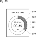
- Reference numerals 521 and 522 denote characters and a gauge that represent a time (hereinafter, called “detection time” for the convenience sake) to be updated based on detection of the predetermined change as one or more pieces of information representing the time.
- the gauge 522 shown in Figs. 5A to 5I has a circular shape where the position with the value of zero is adjacent to the position with the maximum value. However, there is no limitation thereto.
- Reference numeral 523 denotes characters representing an elapsed time after the start of execution of checking of the way of inhalation.
- a UI component 520 is described.
- Fig. 5B represents an example of the UI component 520 immediately after the UI component 510 is selected.
- the detection time represented by the characters 521 is zero, and the current value 530 of the gauge 522 is also zero.
- the elapsed time represented by the characters 523 is also zero.
- Fig. 5C represents an example of the UI component 520 0.52 seconds after the UI component 510 is selected.
- the elapsed time represented by the characters 523 is 0.52 seconds.
- the detection time represented by the characters 521 is 0.35 seconds
- the current value 530 of the gauge 522 is also the value corresponding to 0.35 seconds. That is, Fig. 5C shows that the detection time in the 0.52 seconds after selection of the UI component 510 is 0.35 seconds.
- the detection time is counted based on detection of the predetermined change in principle. However, the time does not necessarily conform to the time during which the predetermined change is detected. At least one of one or more pieces of information representing the detection time that are included in the UI component 520 sometimes represents a detection time different from that of other information.
- Fig. 5I represents an example of such a UI component 520.
- the detection time represented by the characters 521 is 0.15 seconds, while the current value 530 of the gauge 522 is a value corresponding to 0.35 seconds.
- the inhalation action for one time by the user is sometimes intermittent. For example, the user sometimes stop inhalation at the middle of the inhalation action for one time because of breathlessness or the like. If the predetermined change is not detected for a predetermined time or longer, the system 200 can determine that an interruption of inhalation occurs.
- Fig. 5D shows an example of the UI component 520 after occurrence of the interruption of inhalation. Note that this example assumes that the interruption of inhalation occurs when the UI component 520 comes into the state represented in Fig. 5C .
- the elapsed time represented by the characters 523 is 0.98 seconds.
- the detection time represented by the characters 521 is 0.43 seconds
- the current value 530 of the gauge 522 is also the value corresponding to 0.43 seconds. That is, Fig. 5D shows the UI component 520 in a case where the detection time is temporarily reset by the interruption of inhalation, and indicates that the detection time after occurrence of the interruption of inhalation is 0.43 seconds.
- the UI component 520 can indicate that the interruption of inhalation occurs. For example, it is displayed that the gauge 522 in Fig. 5D after occurrence of the interruption of inhalation is different from the gauge 522 in Fig. 5C before occurrence of the interruption of inhalation.
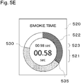
- Fig. 5E shows another example of the UI component 520 after occurrence of the interruption of inhalation. Note that this example assumes that the interruption of inhalation occurs when the UI component 520 comes into the state represented in Fig. 5C .
- the elapsed time represented by the characters 523 is 0.98 seconds.
- the detection time represented by the characters 521 is 0.58 seconds, while the current value 530 of the gauge 522 is the value corresponding to 0.78 seconds. That is, Fig.
- FIG. 5E shows the UI component 520 in a case where the detection time is not reset by the interruption of inhalation even temporarily, and indicates that the characters 521 represent 0.58 seconds and the gauge 522 represents 0.78 seconds respectively as the totals of detection times before and after the interruption of inhalation.
- the UI component 520 can indicate that the interruption of inhalation occurs.
- Fig. 5E shows that the gauge 522 is different before and after reference numeral 535 when the interruption of inhalation occurs.
- Times during which the user is assumed to inhale at least at one time of inhalation are defined as parameters to the first way of inhalation, the second way of inhalation, and the third way of inhalation described above.
- Figs. 5F and 5G represent examples of the UI component 520 0.90 seconds after the UI component 510 is selected.
- the detection time represented by the characters 521 and the gauge 522 is 0.80 seconds.
- the apparent position of the current value 530 of the gauge 522 is different. This is because the maximum values 540 of the gauge 522 in Figs. 5F and 5G are defined as values corresponding to 1.0 second and 2.0 seconds, respectively.
- the maximum value of the gauge 522 is defined based on the reference time defined for this way of inhalation, thereby allowing the user to visually understand whether their way of inhalation is suitable for the way of inhalation to be checked, in terms of the inhalation time.
- the maximum value of the gauge 522 as represented in Figs. 5A to 5I is defined based on the reference time defined for the way of inhalation to be checked, it is particularly advantageous because possible inhalation by the user to cause the position of the value of the gauge goes around just one time allows the way of inhalation assumed with respect to the reference time to be achieved.
- information representing the remaining time from the start of execution of checking the way of inhalation to the lapse of the reference time may be displayed instead of or in addition to the characters 523 representing the elapsed time.
- information representing the reference time itself may be displayed.
- the characters 521 representing the detection time and the characters 523 representing the elapsed time are not necessarily displayed.
- Fig. 5H shows such an example.
- the parameter defined for the way of inhalation may include the strength of inhalation.
- Fig. 6 shows an example screen (hereinafter, called "result viewing screen") 600 for displaying a result of the user's check of the way of inhalation through the flavor inhalation device 100 or the like.
- Reference numeral 610 denotes results of checking of the first way of inhalation, the second way of inhalation and the third way of inhalation.
- the checking of the way of inhalation may include determination of whether the reference time defined for the way of inhalation and the detection time coincide with each other within a predetermined error range, with respect to each of the ways of inhalation.
- the results 610 in this example indicates that the determination is performed two times for each of the first way of inhalation, the second way of inhalation and the third way of inhalation, and the reference time defined for the corresponding way of inhalation and the detection time coincide with each other within the predetermined error range only one time with respect to each of the ways of inhalation.
- the predetermined error is, for example, 0.2 seconds.
- the error may be any of predetermined other values including zero, or a value obtained by multiplying the reference time by a predetermined ratio.
- the predetermined error is not limited thereto. Note that the determination described above may include determination of whether the strength of inhalation defined for the corresponding way of inhalation, and the strength of inhalation by the user estimated based on the output from the detector 210 coincide with each other within the predetermined error range, with respect to each of the ways of inhalation.
- Reference numeral 620 shows an example of UI components for selecting one of the first way of inhalation, the second way of inhalation and the third way of inhalation.
- the UI components 620 may be configured to allow selection of one or more of the first way of inhalation, the second way of inhalation and the third way of inhalation.
- the UI components 620 may be for receiving selection of the way of inhalation that is comfortable for the user.
- the system 200 can transmit the selected way of inhalation to the server 330.
- the server 330 can perform any statistical process based on the received selected way of inhalation.
- the UI components 620 can be configured so as to allow selection from among only ways of inhalation where the defined reference time and the detection time coincide with each other within the predetermined error range at least one time. For example, only for any of such ways of inhalation, the corresponding UI component 620 can be displayed. Such a configuration can improve the possibility that the user's experience is reflected in the way of inhalation transmitted to the server 330, and in turn improve the reliability of the statistical processing in the server 330.
- the detection time used on the result viewing screen 600 is a time obtained by correction in consideration of the difference between the time period during which the user's inhalation action through the flavor inhalation device 100 or the like is detected, and the time period during which the predetermined change occurs.
- the UI components 620 may be for reception of selection of ways of inhalation uncomfortable for the user, and ways of inhalation satisfactory for the user and the like.
- Fig. 7 shows an example screen (hereinafter, called "reference viewing screen") for displaying reference information for the user.
- Reference numeral 710 denotes a graph that represents favorite ratios by users respectively for the first way of inhalation, the second way of inhalation and the third way of inhalation.
- Data for displaying the graph 710 can be generated by the server 330 through statistical processing based on the ways of inhalation selected by multiple users, the ways having been received from multiple systems 200.
- the graph 710 is only an example of information representing the ways of inhalation selected by the multiple users.
- the reference viewing screen 700 may display recommendation information based on the selected way of inhalation in addition to or instead of the graph 710.
- An example of such recommendation information is information about recommended flavors.
- the preferable way of inhalation may be sometimes different.
- the system 200 can display information about the flavor with a preferable inhalation time of one second, as recommendation information. Note that what has been preliminarily stored in the system 200 may be used for data for displaying the recommendation information. What has been generated by the server 330 through statistical processing based on the ways of inhalation selected by multiple users received from multiple systems 200 may be used for the data.
- the system 200 can display a screen (not shown) allowing the user to select a flavor currently used for the flavor inhalation device 100 or the like, and transmits the selected flavor to the server 330.
- the server 330 can generate data for displaying information about a recommended flavor through statistical processing based on the flavors selected by the multiple users, and on the ways of inhalation selected by the multiple users.
- a screen for rechecking or training of the way of inhalation for the sake of allowing the user to perform rechecking or training of the selected way of inhalation may be displayed.
- the screen for rechecking or training of the way of inhalation may include a UI control 510 and a UI control 520 that correspond to the selected way of inhalation.
- Figs. 8A to 8C show flowcharts of an example method 800 executed by the system 200.
- the example method 800 may be executed by the controller 260 of the system 200.
- reference numeral 810 denotes a step of displaying the test screen 400 on the display 220.
- Reference numeral 820 denotes a step of determining whether the predetermined change caused at at least part of the flavor inhalation device 100 or the like is detected, based on an output from the detector 210. If the predetermined change is detected, the processing proceeds to step 830. If not, step 820 is repeated.
- Step 820 may include a step of determining whether the predetermined change is detected, based on the image in the frame 411A in the real-time image 410 included in the output from the detector 210.
- step 820 may include a step of determining whether the predetermined change is detected, based on the image at the predetermined position or in the predetermined range 412 in the real-time image 410 where the changing part 120 should be present when the frame 411B overlaps the flavor inhalation device 100 or the like.
- step 820 does not necessarily require the frame 411, and may determine whether the predetermined change caused at at least part of the flavor inhalation device 100 or the like is detected in the entire real-time image 410.
- Fig. 9 illustrates a flowchart of other example steps that step 820 can include.
- Reference numeral 910 denotes a step of determining whether the flavor inhalation device 100 or the like overlaps the frame 411B in the real-time image 410. If it is determined that the flavor inhalation device 100 or the like overlaps the frame 411B, the processing proceeds to step 920. If not, step 910 is repeated.
- Reference numeral 920 denotes a step of determining whether the predetermined change is detected, based on the image at the predetermined position or in the predetermined range 412 in the real-time image 410 where the changing part 120 should be present when the frame 411B overlaps the flavor inhalation device 100 or the like. If the predetermined change is detected, step 820 is finished. If not, the processing returned to step 910.
- reference numeral 830 denotes a step of displaying the screen 500 for checking the way of inhalation on the display 220.
- Reference numeral 840 denotes a step of determining whether the UI component 510 is selected. This step includes a step of receiving, as a selection, the way of inhalation corresponding to the selected UI component 510 among the multiple ways of inhalation. If it is determined that the UI component 510 is selected, the processing proceeds to step 850. If not, step 840 is repeated.
- Reference numeral 850 denotes a step of initializing the UI component 520.
- This step includes a step of defining the maximum value 540 of the gauge 522 on the basis of the reference time defined for the selected way of inhalation.
- This step may include a step of displaying an instruction about the way of inhalation ("Inhale stronger” etc.), and a message, such as "Start", indicating that the checking of the way of inhalation is started, on the display 220, for the user.
- Reference numeral 855 denotes a step of detecting the predetermined change, and displaying information on the display 220. As described later, step 855 includes a step of displaying information on the basis of the detection of the predetermined change. This step includes a step of controlling the showing of information on the basis of the difference between the time period during which the user's inhalation action through the flavor inhalation device 100 or the like is detected, and the time period during which the predetermined change occurs.
- the difference between the time period during which the user's inhalation action through the flavor inhalation device 100 or the like is detected, and the time period during which the predetermined change occurs is due to a delay from detection of the finish of the user's inhalation action through the flavor inhalation device 100 or the like to the finish of the predetermined change, or a delay from detection of the start of the user's inhalation action to the start of the predetermined change, for example.
- the difference may include one or both of the first predetermined time that is a length of the former delay, and the second predetermined time that is the length of the latter delay.
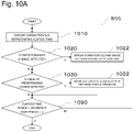
- Fig. 10A shows a flowchart of example steps that step 855 can include.
- Reference numeral 1010 indicates a step of displaying the characters 523 representing the elapsed time, on the display 220.
- Step 1010 includes a step of updating the showing of the characters 523 representing the elapsed time, dependent on the lapse of time.
- Reference numeral 1020 denotes a step of determining whether the predetermined change is detected based on the output from the detector 210. Step 1020 may be a step similar to step 820. If it is determined that the predetermined change is detected, the processing proceeds to step 1022. If not, the processing proceeds to step 1030.
- Reference numeral 1022 indicates a step of displaying the characters 521 and the gauge 522 that represent the detection time, on the display 220.
- Step 1022 includes a step of updating the showing of the characters 521 and the gauge 522 representing the detection time, dependent on the lapse of time.
- Step 1022 is an example of a step of displaying one or more pieces of information for displaying a time so as to indicate a lapse of time in a case where the predetermined change is detected.
- Reference numeral 1030 denotes a step of determining whether the finish of the predetermined change is detected. In step 1030, based on the output from the detector 210, it may be determined that the finish of the predetermined change is detected. Alternatively, in step 1030, it may be determined that the finish of the predetermined change is detected if the determination in preceding step 1020 last time is true but preceding step 1020 is false, using a flag or the like. If it is determined that the finish of the predetermined change is detected, the processing proceeds to step 1032. If not, the processing proceeds to step 1090.
- Reference numeral 1032 indicates a step of returning the showing of the gauge 522 on the display 210 to that the first predetermined time before.
- Step 1032 corresponds to a step of updating the display in Fig. 5C until just before, to the display in Fig. 5I , for example.
- the first predetermined time in this example is 0.2 seconds.
- the first predetermined time may be other than 0.2 seconds, and may be predetermined or may be freely selectable.
- the first predetermined time may be set according to the type of the flavor inhalation device 100 or the like.
- the first predetermined time pertaining to a certain type of the flavor inhalation device 100 or the like may be set to 0.2 seconds, and the first predetermined time pertaining to another type of flavor inhalation device 100 or the like may be set to 0.15 seconds.
- Step 1032 is an example of a step of returning at least one of the one or more pieces of information representing the time to a display at the first predetermined time before, upon detection of the finish of the predetermined change.
- the first predetermined time may be obtained by measuring the time from detection of the finish of the user's inhalation action for each of the flavor inhalation devices 100 or the like to the finish of the predetermined change, and calculating an average value thereof. For example, the time from detection of the finish of the user's inhalation action for each of the same type of flavor inhalation devices 100 or the like to the finish of the predetermined change may be measured, and the average value of the measured times may be adopted as the first predetermined time. The time from detection of the finish of the user's inhalation action for each of different types of the flavor inhalation devices 100 or the like to the finish of the predetermined change may be measured, and the average value of the measured times may be adopted as the first predetermined time.
- the first predetermined time may be separately set to each of multiple flavor inhalation devices 100 or the like.
- the storage 240 of the system 200 stores the first predetermined time with respect to each of the flavor inhalation devices 100 or the like, for example.
- the system 200 then causes the detector 210 to read an identifier (e.g., QR code (R) etc.) indicated on the flavor inhalation device 100 or the like, and executes a step of returning to the indication of the gauge 522 on the display 210 to that the first predetermined time before, using the first predetermined time associated with the identifier.
- an identifier e.g., QR code (R) etc.
- the first predetermined time may be set with respect to each types of the flavor inhalation devices 100 or the like.
- the storage 240 of the system 200 stores the first predetermined time with respect to each type of the flavor inhalation devices 100 or the like, for example.
- the system 200 then causes the detector 210 to read an identifier (e.g., QR code (R) etc.) indicated on the flavor inhalation device 100 or the like, identifies the type of the flavor inhalation device 100 or the like, and executes a step of returning to the indication of the gauge 522 on the display 210 to that the first predetermined time before, using the first predetermined time associated with the type.
- an identifier e.g., QR code (R) etc.
- system 200 may have a function of allowing the user or the like to select the first predetermined time according to the type of the flavor inhalation device 100 or the like, instead of causing the detector 210 to read the identifier (e.g., QR code (R) etc.) indicated on the flavor inhalation device 100 or the like.
- identifier e.g., QR code (R) etc.
- Reference numeral 1090 denotes a step of determining whether the elapsed time is longer than the reference time + ⁇ .
- ⁇ is 0.2 seconds.
- the ⁇ may be any of predetermined other values including zero, or a value obtained by multiplying the reference time by a predetermined ratio. If the elapsed time is longer than the reference time + ⁇ , step 855 is finished. If not, the processing is returned to step 1010.
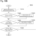
- Fig. 10B shows a flowchart of other example steps that step 855 can include.
- Fig. 10A shows a flowchart of other example steps that step 855 can include.
- Reference numeral 1024 indicates a step of displaying the gauge 522 representing the detection time, on the display 220. Unlike in step 1022, in step 1024 the characters 521 representing the detection time are not displayed. Step 1024 includes a step of updating the showing of the gauge 522 representing the detection time, dependent on the lapse of time. Step 1024 is an example of a step of displaying one or more pieces of first information for displaying a time so as to indicate a lapse of time in a case where the predetermined change is detected.
- Reference numeral 1034 denotes a step of correcting the detection time using the first predetermined time, and displaying the characters 521 representing the detection time on the display 220.
- the correction is made in consideration of the difference between the time period during which the user's inhalation action through the flavor inhalation device 100 or the like is detected, and the time period during which the predetermined change is caused.
- the time represented by the characters 521 may be a time derived by subtracting the first predetermined time from the current detection time.
- Step 1034 is an example of a step of displaying one or more pieces of second information representing a time obtained by subtracting the first predetermined time from the time represented by the one or more pieces of information representing the first time, upon detection of the finish of the predetermined change.
- Fig. 10C shows a flowchart of still other example steps that step 855 can include.
- Figs. 10A and 10B the flowchart shown in Fig. 10C is described.
- Reference numeral 1050 denotes a step of determining whether the predetermined change is continuously detected for the first predetermined time or longer. In step 1050, it may be determined that the predetermined change is continuously detected for the first predetermined time or longer on the basis of the output from the detector 210 and using the flag or the like, if the finish of the predetermined change has not been detected for the first predetermined time or longer since detection of the start of the predetermined change, as described later.
- Step 1032 in Fig. 10C is an example of a step of displaying one or more pieces of information for displaying a time so as to indicate a lapse of time if the predetermined change has been continuously detected for the first predetermined time or longer.
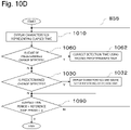
- Fig. 10D shows a flowchart of yet other example steps that step 855 can include.
- Figs. 10A to 10C the flowchart shown in Fig. 10D is described.
- Reference numeral 1060 denotes a step of determining whether the start of the predetermined change is detected based on the output from the detector 210. In this step, it may be determined that the start of the predetermined change is detected by using a flag or the like, if the predetermined change is detected for the first time, or if the predetermined change is detected after the finish of the predetermined change is detected and before the start of the predetermined change is detected.
- Reference numeral 1062 denotes a step of correcting the detection time using the second predetermined time.
- the correction in step 1062 may be, for example, addition of the second predetermined time to the current detection time.
- Steps 1062 and 1032 in Fig. 10D are examples of a step of, when the predetermined change is detected, displaying one or more pieces of information representing a time so as to indicate a lapse of time, as if the start of the predetermined change would have been detected the second predetermined time before from actual detection of the start of the predetermined change.
- Steps included in the flowcharts illustrated in Figs. 10A to 10D are example steps included in step 855. Accordingly, for example, step 855 may include a combination of a step illustrated in any of Figs. 10A to 10C , and a step illustrated in Fig. 10D .
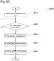
- reference numeral 860 denotes a step of determining whether the user's way of inhalation matches the way of inhalation corresponding to the selected UI component 510.
- This step can include a step of determining whether the reference time defined for the way of inhalation associated with the selected UI component 510 and the detection time coincide with each other within the predetermined error range.
- the detection time is a time obtained by correction in consideration of the difference between the time period during which the user's inhalation action through the flavor inhalation device 100 or the like is detected, and the time period during which the predetermined change occurs.
- the predetermined error may be the same as ⁇ described above. However, there is no limitation thereto.
- This step may include a step of determining whether the strength of inhalation by the user and the strength of inhalation defined for the way of inhalation associated with the selected UI component 510 match each other within a predetermined error range. If the ways of inhalation match each other, the processing proceeds to step 862. If not, the processing proceeds to step 864.
- Reference numerals 862 and 864 denote a step of updating the showing of the selected UI component 510 to the first showing (in this example, double circles) and the second showing (in this example, triangles), respectively. Note that these steps may include a step of displaying, for the user, a message, such as "Finish", indicating that the checking of the way of inhalation is finished.
- Reference numeral 866 denotes a step of determining whether an unselected UI component 510 is present. If the component is present, the processing returns to step 840. If not, the processing proceeds to step 870.
- reference numeral 870 denotes a step of displaying the result viewing screen 600 on the display 220.
- This step may include a step of displaying, on the display 220, a message about a reference for selecting the way of inhalation selected through the result viewing screen 600 (for example, "Select way of inhalation felt comfortable”, “Select way of inhalation felt uncomfortable”, “Select way of inhalation felt satisfactory” or the like).
- Reference numeral 880 denotes a step of determining whether the UI component 620 is selected. This step includes a step of receiving, as a selection, the way of inhalation corresponding to the selected UI component 620 among the multiple ways of inhalation. If it is determined that the UI component 620 is selected, the processing proceeds to step 882. If not, step 880 is repeated.
- Reference numeral 882 denotes a step of transmitting the selected way of inhalation to the server 330.
- Reference numeral 884 denotes a step of receiving, from the server 330, data for displaying information representing the ways of inhalation selected by multiple users. This step may include a step of receiving, from the server 330, data for displaying recommendation information.
- Reference numeral 890 denotes a step of displaying the reference viewing screen 700 on the display 220. Step 890 may display the screen for rechecking or training of the way of inhalation, in addition to or instead of the reference viewing screen 700.
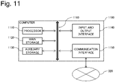
- Fig. 11 shows an example of a hardware configuration of a computer.
- the computer 1100 mainly includes, as hardware resources: a processor 1110; a main storage device 1120; an auxiliary storage device 1130; an input and output interface 1140; and a communication interface 1150. These components are connected to each other via a bus line 1160 that includes an address bus, a data bus, a control bus and the like. Note that an interface circuit (not shown) sometimes intervenes between the bus line 1160 and each of the hardware resources.
- the processor 1110 controls the entire computer.
- the main storage device 1120 provides the processor 1110 with a work area, and is a volatile memory, such as an SRAM (Static Random Access Memory) and a DRAM (Dynamic Random Access Memory).
- SRAM Static Random Access Memory
- DRAM Dynamic Random Access Memory
- the auxiliary storage device 1130 is a nonvolatile memory, such as an HDD, an SSD, and a flash memory, for storing a program and the like serving as software, and data and the like.
- the program, data and the like are loaded from the auxiliary storage device 1130 to the main storage device 1120 via the bus line 1160 at any time point.
- the auxiliary storage device 1130 may sometimes be referred to as a non-transitory computer-readable storage medium.
- the input and output interface 1140 performs both or one of information presentation and information inputting, and is a digital camera, a keyboard, a mouse, a display, a touch panel display, a microphone, a speaker, and a temperature sensor, etc.
- the communication interface 1150 is connected to the network 320, and transmits and received data via the network 320.
- the communication interface 1150 and the network 320 may be connected to each other by wire or wirelessly.
- the communication interface 1150 can also obtain information about the network, for example, information about Wi-Fi access point, information about base stations of communication carriers and the like.
Landscapes
- Engineering & Computer Science (AREA)
- Physics & Mathematics (AREA)
- Computer Hardware Design (AREA)
- General Physics & Mathematics (AREA)
- Theoretical Computer Science (AREA)
- Human Computer Interaction (AREA)
- User Interface Of Digital Computer (AREA)
- Selective Calling Equipment (AREA)
Abstract
Description
- The present invention relates to a flavor inhalation device, or an aerosol generating device. In more detail, the present invention relates to checking of a way of inhalation through a flavor inhalation device or an aerosol generating device.
- Conventionally, techniques about smoking devices, such as electronic cigarettes, have been developed (for example, see PTL 1).
- PTL 1: National Publication of International Patent Application No.
2017-512459 - The way of inhalation through a smoking device, such as an electronic cigarette, has not been established. The way of inhalation varies by individual. Accordingly, a user's way of inhalation is cannot be regarded suitable for this user in some cases. In the current situation, the way of inhalation is described by text, and in addition, the way of another person's inhalation is represented by illustration, a video, etc. However, these only indicate situations of the other person's inhalation, which are sometimes difficult for a user to understand. Accordingly, the user who uses a smoking device, such as an electronic cigarette, for the first time is sometimes confused.
- Consequently, if the user can check the way of inhalation through a smoking device, such as an electronic cigarette while having an experience, this is useful for them. Note that it is believed that the checking of the way of inhalation is useful not only for electronic cigarettes, but also for heated tobacco products (accompanied by no tobacco combustion), conventional tobacco products (accompanied by tobacco combustion), medical nebulizers and the like.
- In view of the above description, a program and the like for allowing a user to check the way of inhalation through a flavor inhalation device or an aerosol generating device (hereinafter, also called "flavor inhalation device etc.") while having an experience has been invented. Here, "flavor inhalation device" is a device for inhaling a flavor. Without any limiting intention, the device encompasses, for example, electronic cigarettes, heated tobacco products, and conventional tobacco products. The "aerosol generating device" is a device for inhaling generated aerosols. Without any limiting intention, the device encompasses, for example, electronic cigarettes, heated tobacco products, and medical nebulizers.
- The invention described above uses an externally observable predetermined change that is caused based on the user's inhalation action and is caused at at least part of the flavor inhalation device or the like. With respect to this point, the inventor of this application has realized that with some flavor inhalation devices and the like, the user's inhalation time period deviates from a time period in which the externally observable predetermined change occurs. For example, it has been found that with a certain flavor inhalation device, according to the specifications, upon detection of the start of the user's inhalation action, an externally observable predetermined change is simultaneously started, while after detection of completion of the user's inhalation action, the externally observable predetermined change is not immediately finished. If the user's inhalation action is detected simply by using the predetermined change at such a flavor inhalation device or the like, the detection result is different from the user's experience.
- Furthermore, the inventor of this application has realized that some designs of flavor inhalation devices and the like reduce the accuracy of detecting the predetermined change. This means that if the user's inhalation action is intended to be detected using the conventional technique, limitation occurs on the designs of the flavor inhalation devices and the like.
- The present invention has been made in view of the above description, and has an object to provide an improved program and the like for allowing the user to check the way of inhalation through a flavor inhalation device and the like while having an experience.
- An embodiment of the present invention provides a program causing a computer to execute: detecting an externally observable predetermined change caused at at least part of a flavor inhalation device or an aerosol generating device, the predetermined change being caused based on a user's inhalation action through the flavor inhalation device or the aerosol generating device; and displaying information, based on detection of the predetermined change, wherein said displaying information based on detection of the predetermined change includes controlling a showing of the information based on a difference between a time period during which the user's inhalation action is detected through the flavor inhalation device or the aerosol generating device, and a time period during which the predetermined change is caused.
- According to such a configuration, even if the user's inhalation time period is different from the time period during which the predetermined change is caused in an aerosol inhalation device or the like, appropriate information can be provided for the user on the basis of detection of the predetermined change.
- In one embodiment, the difference may include a first predetermined time from detection of a finish of the user's inhalation action through the flavor inhalation device or the aerosol generating device to a finish of the predetermined change.
- According to such a configuration, even if the finish of the predetermined change in an aerosol inhalation device or the like delays from the finish of inhalation by the user, appropriate information can be provided for the user on the basis of detection of the predetermined change.
- In one embodiment, said displaying information based on detection of the predetermined change may further include; displaying one or more pieces of information representing a time so as to indicate a lapse of time in a case where the predetermined change is detected, and said controlling the showing of information may include returning at least one of the one or more pieces of information representing the time to a display at the first predetermined time before, upon detection of the finish of the predetermined change.
- In one embodiment, said displaying information based on detection of the predetermined change may further include: displaying one or more pieces of first information representing a time so as to indicate a lapse of time in a case where the predetermined change is detected, and wherein said controlling the showing of information may include displaying one or more pieces of second information representing a time obtained by subtracting the first predetermined time from the time represented by the one or more pieces of first information, upon detection of the finish of the predetermined change.
- In one embodiment, said controlling the showing of information may include: displaying one or more pieces of information representing a time so as to indicate a lapse of time in a case where the predetermined change has been detected for the first predetermined time or longer.
- Such a configuration can provide the user with information for checking the way of inhalation in conformity with the experience.
- In one embodiment, which is a program according to any one of
claims 1 to 5, the difference may include a second predetermined time from detection of a start of the user's inhalation action through the flavor inhalation device or the aerosol generating device to a start of the predetermined change. - According to such a configuration, even if the start of the predetermined change through an aerosol inhalation device or the like delays from the start of inhalation by the user, appropriate information can be provided for the user on the basis of detection of the predetermined change.
- In one embodiment, said controlling the showing of information may include displaying, in a case where the predetermined change is detected, one or more pieces of information representing a time so as to indicate a lapse of time and as if the start of the predetermined change would have been detected the second predetermined time before from actual detection of the start of the predetermined change.
- Such a configuration can provide the user with information for checking the way of inhalation in conformity with the experience.
- In one embodiment, the one or more pieces of information representing the time may include a character and a gauge, and said at least one of the one or more pieces of information representing the time may include the gauge.
- In one embodiment, the one or more pieces of first information representing the time may include a gauge, and the one or more pieces of second information representing the time may include a character.
- In one embodiment, the one or more pieces of information representing the time may include a character and/or a gauge.
- Such a configuration can provide the user with easily understandable information for checking the way of inhalation.
- An embodiment of the present invention provides a computer-implemented method including: detecting an externally observable predetermined change caused at at least part of a flavor inhalation device or an aerosol generating device, the predetermined change being caused based on a user's inhalation action through the flavor inhalation device or the aerosol generating device; and displaying information based on detection of the predetermined change, wherein said displaying information based on detection of the predetermined change includes controlling a showing of the information based on a difference between a time period during which the user's inhalation action is detected through the flavor inhalation device or the aerosol generating device, and a time period during which the predetermined change is caused.
- Furthermore, an embodiment of the present invention provides a system comprising: a detector; a display; and a controller configured to detect an externally observable predetermined change caused at at least part of a flavor inhalation device or an aerosol generating device based on an output from the detector, the predetermined change being caused based on a user's inhalation action through the flavor inhalation device or the aerosol generating device, and display on the display, information based on detection of the predetermined change, wherein the controller is further configured to control a showing of the information, based on a difference between a time period during which the user's inhalation action is detected through the flavor inhalation device or the aerosol generating device, and a time period during which the predetermined change is caused.
- According to such a configuration, even if the user's inhalation time period is different from the time period during which the predetermined change is caused in the aerosol inhalation device or the like, appropriate information can be provided for the user on the basis of detection of the predetermined change.
- An embodiment of the present invention provides a program causing a computer to execute: displaying a real-time image obtained, and a frame in the real-time image, the frame conforming to a shape of a flavor inhalation device or an aerosol generating device; detecting an externally observable predetermined change caused at at least part of the flavor inhalation device or the aerosol generating device, based on an image at a predetermined position or in a predetermined range in the real-time image, the predetermined change being caused based on a user's inhalation action through the flavor inhalation device or the aerosol generating device; and displaying information based on detection of the predetermined change.
- In one embodiment, the predetermined position or the predetermined range may be in the frame.
- In one embodiment, the predetermined position or the predetermined range may be out of the frame.
- According to such a configuration, the user can easily position the flavor inhalation device or the like in order to detect the predetermined change in the flavor inhalation device or the like. According to such a configuration, the limited portion in the real-time image is used to detect the predetermined change in the flavor inhalation device or the like, thereby improving the accuracy of detecting the predetermined change in the flavor inhalation device or the like having a confusing design from the predetermined change.
- The program according to one embodiment may further causing the computer to execute: determining whether the flavor inhalation device or the aerosol generating device overlaps the frame, based on the real-time image in the frame; and executing said detecting an externally observable predetermined change caused at at least part of the flavor inhalation device or the aerosol generating device, upon determination that the flavor inhalation device or the aerosol generating device overlaps the frame.
- According to such a configuration, only when the flavor inhalation device or the like is present at an appropriate position in the real-time image, the limited portion in the real-time image is used to detect the predetermined change in the flavor inhalation device or the like, thereby further improving the accuracy of detecting the predetermined change in the flavor inhalation device or the like having a confusing design from the predetermined change.
- An embodiment of the present invention provides a computer-implemented method including: displaying a real-time image obtained, and a frame in the real-time image, the frame conforming to a shape of a flavor inhalation device or an aerosol generating device; detecting an externally observable predetermined change caused at at least part of the flavor inhalation device or the aerosol generating device, based on an image at a predetermined position or in a predetermined range in the real-time image, the predetermined change being caused based on a user's inhalation action through the flavor inhalation device or the aerosol generating device; and displaying information, based on detection of the predetermined change.
- Furthermore, an embodiment of the present invention provides a system comprising: a detector; a display; and a controller configured to display, on the display, a real-time image and a frame in the real-time image, the real-time image obtained by the detector, and the frame conforming to a shape of a flavor inhalation device or an aerosol generating device; detect an externally observable predetermined change caused at at least part of the flavor inhalation device or the aerosol generating device, based on an image at a predetermined position or in a predetermined range in the real-time image, the predetermined change being caused based on a user's inhalation action through the flavor inhalation device or the aerosol generating device; and display, on the display, information based on detection of the predetermined change.
- According to such a configuration, the user can easily position the flavor inhalation device or the like in order to detect the predetermined change in the flavor inhalation device or the like. According to such a configuration, the limited portion in the real-time image is used to detect the predetermined change in the flavor inhalation device or the like, thereby improving the accuracy of detecting the predetermined change in the flavor inhalation device or the like having a confusing design from the predetermined change.
- The present invention allows the user to check the way of inhalation through a flavor inhalation device and the like while having an experience.
-
-
Fig. 1A is a block diagram of an example configuration of aflavor inhalation device 100 or the like according to one embodiment of the present invention. -
Fig. 1B shows a schematic appearance of an example of theflavor inhalation device 100 or the like. -
Fig. 1C shows a schematic appearance of an example of theflavor inhalation device 100 or the like. -
Fig. 2 is a block diagram of an example configuration of a system 200 according to one embodiment of the present invention. -
Fig. 3 is a block diagram of an example configuration of asystem 300 according to one embodiment of the present invention. -
Fig. 4A shows anexample screen 400A for testing detection of a predetermined change of theflavor inhalation device 100 or the like. -
Fig. 4B shows anexample screen 400B for testing detection of a predetermined change of theflavor inhalation device 100 or the like. -
Fig. 5A shows anexample screen 500 for allowing a user to check the way of inhalation through theflavor inhalation device 100 or the like. -
Fig. 5B shows an example of a UI (user interface)component 520. -
Fig. 5C shows an example of theUI component 520. -
Fig. 5D shows an example of theUI component 520. -
Fig. 5E shows an example of theUI component 520. -
Fig. 5F shows an example of theUI component 520. -
Fig. 5G shows an example of theUI component 520. -
Fig. 5H shows an example of theUI component 520. -
Fig. 5I shows an example of theUI component 520. -
Fig. 6 shows anexample screen 600 for displaying a result of the user's check of the way of inhalation through theflavor inhalation device 100 or the like. -
Fig. 7 shows anexample screen 700 for displaying reference information for the user. -
Fig. 8A shows a flowchart of anexample method 800 executed by the system 200. -
Fig. 8B shows a flowchart of anexample method 800 executed by the system 200. -
Fig. 8C shows a flowchart of anexample method 800 executed by the system 200. -
Fig. 9 shows a flowchart of an example step that step 820 includes. -
Fig. 10A shows an example flowchart of steps that step 855 includes. -
Fig. 10B shows an example flowchart of steps that step 855 includes. -
Fig. 10C shows an example flowchart of steps that step 855 includes. -
Fig. 10D shows an example flowchart of steps that step 855 includes. -
Fig. 11 shows an example of a hardware configuration of a computer. -
Fig. 1A is a block diagram of an example configuration of aflavor inhalation device 100 or the like according to one embodiment of the present invention.Fig. 1A schematically and conceptually shows each of components included in theflavor inhalation device 100 or the like. It should be noted that the diagram does not show the strict arrangements, shapes dimensions, positional relationships and the like of the components and theflavor inhalation device 100 or the like. It should also be noted that theflavor inhalation device 100 or the like can include components, not shown, for example, a tobacco capsule, a liquid cartridge, etc. -
Reference numeral 110 denotes a sensor for detecting the user's inhalation action. Thesensor 110 may be any sensor for detecting the user's inhalation action; for example, the sensor may be a flow rate sensor, a flow velocity sensor, a pressure sensor, etc. Thesensor 110 may be a button that the user presses to perform an inhalation action. Note that thesensor 110 may be, for example, an inhalation sensor, and detect the user's inhalation through theflavor inhalation device 100 or the like. Thesensor 110 may be an airflow sensor, and detect an airflow caused by user's inhalation. -
Reference numeral 120 denotes a changing part where an externally observable predetermined change occurs. The changingpart 120 may be an LED (Light Emitting Diode) that emits light with a predetermined color, for example, a blue LED. The predetermined change may be emission of light with a predetermined color, e.g., blue. Note that the predetermined color is not limited to blue. Any color may be adopted. The predetermined change may be change in color of emitted light or change in emitted light intensity dependent on the strength of inhalation; the change is detected by thesensor 110. The changingpart 120 is not limited to an LED, and may be a light source that has another configuration and emit light with the predetermined color. - The arrangement of the changing
part 120 is described with reference toFigs. 1B and1C . -
Fig. 1B shows a schematic appearance of an example of theflavor inhalation device 100 or the like. As shown inFig. 1B , although not limited, theflavor inhalation device 100 or the like has a stick shape that includes two ends 161 and 162 in some cases. Here, the user holds oneend 161 in the mouth for inhalation. Note that the user may hold the oneend 161 in the mouth via a mouthpiece attachable to theend 161. In theflavor inhalation device 100 or the like shown inFig. 1B , the changingpart 120 is provided at theother end 162 between the two ends described above, and has a substantially rectangular shape. -
Fig. 1C shows a schematic appearance of another example of theflavor inhalation device 100 or the like. The differences of theflavor inhalation device 100 or the like shown inFig. 1C from that shown inFig. 1B are the position and the shape of the changingpart 120. That is, in theflavor inhalation device 100 or the like shown inFig. 1C , the changingpart 120 is provided at a substantially intermediate portion between theend 161 and theend 162, and has an annular shape. - Note that the changing
part 120 is at least part of the external surface of theflavor inhalation device 100 or the like, and may be, for example, a substantially rectangular shape or an annular shape as represented inFigs. 1B and1C , or alternatively any shape, such as an annular shape (not shown) along the periphery of theflavor inhalation device 100 or the like. -
Reference numeral 121 inFigs. 1B and1C denotes a design that is applied to theflavor inhalation device 100 or the like and is confusing from a predetermined change. Thedesign 121 can be, for example, a pattern with the predetermined color in a case where the predetermined change is emission of light with a predetermined color. InFigs. 1B and1C , thedesign 121 is close to the changingpart 120, but thedesign 121 may reside at any portion of theflavor inhalation device 100 or the like in some cases. Any shape of thedesign 121 can be adopted. One or moreinconsecutive designs 121 may reside in some cases. Note that theflavor inhalation device 100 or the like may have nodesign 121 in some cases. - Returning to
Fig. 1A ,reference numeral 130 denotes a controller that detects inhalation by the user through theflavor inhalation device 100 or the like at least on the basis of a signal from thesensor 110, and allows the changingpart 120 to cause a predetermined change upon detection of the inhalation. For example, thecontroller 130 may detect inhalation by the user through theflavor inhalation device 100 or the like on the basis of a fact that the strength of inhalation determined based on the intensity of the signal from thesensor 110 or on the signal (hereinafter, called "sensor signal etc."), and upon detection of the inhalation, the controller may cause emission of light with the predetermined color at the changingpart 120. For example, thecontroller 130 may change the color of light emission or the intensity of light emission, dependent on the strength of inhalation determined based on the intensity of the signal from the sensor or the on the signal. For example, thecontroller 130 may increase the intensity of light emission when the inhalation is strong, and reduce the intensity of light emission at the changingpart 120 when the inhalation is weak. For example, thecontroller 130 may classify the strength of inhalation into multiple stages, assign the multiple stages predetermined colors, respectively, and emit the light of the predetermined color associated with the strength of inhalation. Note that thecontroller 130 can detect the finish of inhalation by the user through theflavor inhalation device 100 or the like. Upon detection of the finish of inhalation, the controller can finish the predetermined change at the changingpart 120. For example, thecontroller 130 may detect the finish of inhalation by the user through theflavor inhalation device 100 or the like, based on a fact that the sensor signal or the like becomes equal to or less than a predetermined threshold. Upon detection of the finish of inhalation, the controller may finish the predetermined change at the changingpart 120. Thecontroller 130 may be an electronic circuit module configured as a microprocessor or a microcomputer. - Ideally, it is preferable that the time period during which the user is inhaling through the
flavor inhalation device 100 or the like should coincide with the time period during which the predetermined change is caused. However, according to various reasons, the former time period is sometimes different from the latter time period in actuality. Specifically, there is sometimes a delay between determination that the inhalation by the user is finished, and the finish of the predetermined change. Instead of or in addition to the delay, a delay may be present between determination that the inhalation by the user is started, and a start of the predetermined change. -
Fig. 2 is a block diagram of an example configuration of a system 200 according to one embodiment of the present invention.Fig. 2 schematically and conceptually shows each of components included in the system 200. It should be noted that the diagram does not show the strict arrangements, shapes dimensions, positional relationships and the like of the components and the system 200. It should be further noted that the system 200 can include a component, not shown. The example of the system 200 is a single computer, such as a smartphone, a tablet, or a personal computer. However, there is no limitation thereto. For example, adetector 210 described later may be achieved by a digital camera externally connected to a computer. -
Reference numeral 210 denotes a detector for detecting an externally observable predetermined change that is caused at at least part of theflavor inhalation device 100 or the like, for example, the changingpart 120. Thedetector 210 may be achieved using at least a typical digital camera, a temperature sensor and the like that are hardware resources. Similar to a typical digital camera, the temperature sensor includes a thermography camera that outputs a two-dimensional image. -
Reference numeral 220 denotes a display that displays information based on detection of the predetermined change. Thedisplay 220 may be achieved using at least a display (which may include a touch panel display) as hardware resources. -
Reference numeral 230 denotes an input interface for receiving an input from the user. Theinput interface 230 may be achieved using at least a keyboard, a mouse, a touch panel display as hardware resources. -
Reference numeral 240 denotes a storage for storing a program, data and the like. Thestorage 240 may be achieved using at least an HDD (Hard Disk Drive), an SSD (Solid State Drive), a memory and the like as hardware resources. Thestorage 240 may sometimes be referred to as a non-transitory computer-readable storage medium. -
Reference numeral 250 denotes a communication interface for communication with another computer. Thecommunication interface 250 may be achieved using at least a network interface and the like as hardware resources. -
Reference numeral 260 denotes a controller for performing various types of controls. Thecontroller 260 may be achieved using at least a processor and the like as hardware resources. - The
controller 260 may be configured to make a determination related to the user's way of inhalation. Note that the determination related to user's way of inhalation includes detection of a predetermined change caused at the changingpart 120 of theflavor inhalation device 100 or the like, and displaying of information based on the detection of the predetermined change. Thedisplay 220 can further display a result of the determination. Thecontroller 260 may be configured to allow the user to select one of multiple ways of inhalation, through theinput interface 230. Note that thedisplay 220 can further display information based on the selected way of inhalation. Furthermore, thecontroller 260 may be configured to transmit and receive data via thecommunication interface 250. Note that thedisplay 220 can further display information based on the received data. -
Fig. 3 is a block diagram of an example configuration of asystem 300 according to one embodiment of the present invention.Fig. 3 schematically and conceptually shows each of components included in thesystem 300. It should be noted that the diagram does not show the strict arrangements, shapes dimensions, positional relationships and the like of the components and thesystem 300. It should be further noted that thesystem 300 can include a component, not shown. Note that thesystem 300 includes theflavor inhalation device 100 or the like, and the system 200, as its components. - Reference numerals 100A and 100B correspond to the
flavor inhalation device 100 or the like. -
Reference numerals -
Reference numerals systems -
Reference numeral 320 denotes one or more networks that include the Internet. Note that thesystems network 320. -
Reference numeral 330 denotes one or more servers each of which includes one or more computers. At least part of theserver 330 may provide thesystems systems systems systems - Hereinafter, an example screen displayed on the
display 220 is described. It is assumed that in the following description, thedetector 210 is achieved using a camera as hardware resources. -
Fig. 4A shows an example screen (hereinafter called "first test screen") 400A for performing a test pertaining to detection of the predetermined change at theflavor inhalation device 100 or the like. -
Reference numeral 410 denotes a real-time image from thedetector 210.Reference numeral 411A denotes a frame drawn in a predetermined region in the real-time image 410. - Through the
test screen 400, the user is prompted to take a video in a state of intending to inhale through theflavor inhalation device 100 or the like. In more detail, the user is prompted to adjust the relative distance between themselves and thedetector 210, and their attitude, so as to accommodate the changingpart 120 of theflavor inhalation device 100 or the like in the frame 411, preferably to accommodate only the changingpart 120 in theframe 411A. The user then performs an inhalation action. When the system 200 detects a change caused at the changingpart 120 in theframe 411A, the system 200 determines that the detection has succeeded. - A technical meaning of detection using the
frame 411A is described. An example of the change caused at the changingpart 120 is emission of light with the predetermined color as described above. Here, for example, in a case where the predetermined color is blue, with the user wearing blue clothes, detection from the entire real-time image 410 possibly leads to erroneous detection of the blue clothes worn by the user as blue light emission. That is, detection using theframe 411A has a purpose to improve the accuracy of detecting the predetermined change. - Note that the predetermined change may be detected using any image recognition algorithm. Accordingly, if the image recognition algorithm to be used has a good performance, and can sufficiently discriminate the predetermined change from the other changes, the
frame 411A is not necessarily provided, and the predetermined change may be detected from the entire real-time image 410. -
Fig. 4B shows another example screen (hereinafter called "second test screen") 400B for performing a test pertaining to detection of the predetermined change at theflavor inhalation device 100 or the like. The difference of thesecond test screen 400B from thefirst test screen 400A is the shape and technical meaning of the frame drawn in the predetermined area in the real-time image 410. - That is, unlike the
frame 411A, aframe 411B has a shape conforming to the shape of theflavor inhalation device 100 or the like. The shape conforming to theflavor inhalation device 100 or the like is, for example, a shape (hereinafter called "first shape") that allows the entireflavor inhalation device 100 or the like to conform to theframe 411B by adjusting the relative distance between the user and thedetector 210 and their attitude. Alternatively, the shape conforming to theflavor inhalation device 100 or the like is, for example, a shape (hereinafter called "second shape") that allows only a specified part of theflavor inhalation device 100 or the like to conform to theframe 411B by adjusting the relative distance between the user and thedetector 210 and their attitude. Alternatively, the shape conforming to theflavor inhalation device 100 or the like is, for example, a shape (hereinafter called "third shape") that allows only a specified design, such as a pattern, applied to theflavor inhalation device 100 or the like to conform to theframe 411B by adjusting the relative distance between the user and thedetector 210 and their attitude. - A technical meaning of detection using the
frame 411B is described. As described above, aconfusing design 121 from the predetermined change is sometimes applied to theflavor inhalation device 100 or the like. In such a case, in particular, when the changingpart 120 is close to thedesign 121, detection using theframe 411A possibly leads to erroneous detection that the entrance of thedesign 121 into theframe 411A is regarded as occurrence of the predetermined change. On the other hand, the erroneous detection described above can be at least reduced by detecting the predetermined change using theframe 411B, based on an image at a predetermined position or in a predetermined range 412 (not necessarily displayed on the real-time image 410) in the real-time image 410 where the changingpart 120 is assumed to be present when this frame overlaps theflavor inhalation device 100 or the like, more specifically, on one or more pixels included in the image. - When the
frame 411B has the first shape, the predetermined position or the predetermined range is present in theframe 411B. However, when theframe 411B has the second shape or the third shape, the predetermined position or the predetermined range is present in theframe 411B in some cases and outside this frame in other cases. - Detection of the predetermined change may be tried only when the
frame 411B overlaps theflavor inhalation device 100 or the like. Note that "theframe 411B overlaps theflavor inhalation device 100 or the like" means that theframe 411B overlaps the specified part of theflavor inhalation device 100 or the like when theframe 411B has the second shape. When theframe 411B has the third shape, this means that theframe 411B overlaps the specified design applied to theflavor inhalation device 100 or the like. The determination may be made using any image recognition algorithm. It should be noted that theframe 411B is not necessarily completely overlaid on theflavor inhalation device 100 or the like (or the specified part or the specified design of theflavor inhalation device 100 or the like), but the determination may be performed in consideration of a predetermined error or deviation. - Hereinafter, the
first test screen 400A and thesecond test screen 400B are collectively called "test screen 400". Theframes -
Fig. 5A is an example screen (hereinafter, called "screen for checking the way of inhalation") 500 for allowing the user to check the way of inhalation through theflavor inhalation device 100 or the like. Note thatFig. 5A shows a case of using theframe 411B. Thescreen 500 for checking the way of inhalation may use theframe 411A, instead. -
Reference numeral 510 denotes six UI components (hereinafter, referred to by reference numerals 511 to 516 from left) for executing the checking of the way of inhalation. The UI components 511 and 512, the UI components 513 and 514, and the UI components 515 and 516 are for executing checks pertaining to a first way of inhalation, a second way of inhalation, and a third way of inhalation, respectively. Note that the checks pertaining to the way of inhalation are not limited to checks pertaining to the three ways of inhalation. The number of ways may be freely defined. The check pertaining to one way of inhalation is assumed to be executed multiple time. Note that the check pertaining to the one way of inhalation is required to be executed only one time. The check is not necessarily required to be executed multiple times. The check at each time starts by selecting a corresponding one of the UI components 511 to 516. Thescreen 500 for checking the way of inhalation shown inFig. 5A is a screen in a case where the first check pertaining to the first way of inhalation is finished, the second check pertaining to the first way of inhalation is in execution, and the checks pertaining to the second and third ways of inhalation have not been executed yet. -
Reference numeral 520 denotes a UI component for displaying information on the basis of detection of the externally observable predetermined change caused at at least part of theflavor inhalation device 100 or the like, for example, changingpart 120.Reference numerals gauge 522 shown inFigs. 5A to 5I has a circular shape where the position with the value of zero is adjacent to the position with the maximum value. However, there is no limitation thereto.Reference numeral 523 denotes characters representing an elapsed time after the start of execution of checking of the way of inhalation. - Hereinafter, referring to
Figs. 5B to 5I , an example of aUI component 520 is described. -
Fig. 5B represents an example of theUI component 520 immediately after theUI component 510 is selected. InFig. 5B , the detection time represented by thecharacters 521 is zero, and thecurrent value 530 of thegauge 522 is also zero. InFig. 5B , the elapsed time represented by thecharacters 523 is also zero. -
Fig. 5C represents an example of theUI component 520 0.52 seconds after theUI component 510 is selected. InFig. 5C , the elapsed time represented by thecharacters 523 is 0.52 seconds. On the other hand, the detection time represented by thecharacters 521 is 0.35 seconds, and thecurrent value 530 of thegauge 522 is also the value corresponding to 0.35 seconds. That is,Fig. 5C shows that the detection time in the 0.52 seconds after selection of theUI component 510 is 0.35 seconds. - Note that the detection time is counted based on detection of the predetermined change in principle. However, the time does not necessarily conform to the time during which the predetermined change is detected. At least one of one or more pieces of information representing the detection time that are included in the
UI component 520 sometimes represents a detection time different from that of other information.Fig. 5I represents an example of such aUI component 520. The detection time represented by thecharacters 521 is 0.15 seconds, while thecurrent value 530 of thegauge 522 is a value corresponding to 0.35 seconds. - The inhalation action for one time by the user is sometimes intermittent. For example, the user sometimes stop inhalation at the middle of the inhalation action for one time because of breathlessness or the like. If the predetermined change is not detected for a predetermined time or longer, the system 200 can determine that an interruption of inhalation occurs.
-
Fig. 5D shows an example of theUI component 520 after occurrence of the interruption of inhalation. Note that this example assumes that the interruption of inhalation occurs when theUI component 520 comes into the state represented inFig. 5C . InFig. 5D , the elapsed time represented by thecharacters 523 is 0.98 seconds. On the other hand, the detection time represented by thecharacters 521 is 0.43 seconds, and thecurrent value 530 of thegauge 522 is also the value corresponding to 0.43 seconds. That is,Fig. 5D shows theUI component 520 in a case where the detection time is temporarily reset by the interruption of inhalation, and indicates that the detection time after occurrence of the interruption of inhalation is 0.43 seconds. Note that theUI component 520 can indicate that the interruption of inhalation occurs. For example, it is displayed that thegauge 522 inFig. 5D after occurrence of the interruption of inhalation is different from thegauge 522 inFig. 5C before occurrence of the interruption of inhalation. -
Fig. 5E shows another example of theUI component 520 after occurrence of the interruption of inhalation. Note that this example assumes that the interruption of inhalation occurs when theUI component 520 comes into the state represented inFig. 5C . InFig. 5E , the elapsed time represented by thecharacters 523 is 0.98 seconds. On the other hand, the detection time represented by thecharacters 521 is 0.58 seconds, while thecurrent value 530 of thegauge 522 is the value corresponding to 0.78 seconds. That is,Fig. 5E shows theUI component 520 in a case where the detection time is not reset by the interruption of inhalation even temporarily, and indicates that thecharacters 521 represent 0.58 seconds and thegauge 522 represents 0.78 seconds respectively as the totals of detection times before and after the interruption of inhalation. Note that theUI component 520 can indicate that the interruption of inhalation occurs. For example,Fig. 5E shows that thegauge 522 is different before and afterreference numeral 535 when the interruption of inhalation occurs. - Times during which the user is assumed to inhale at least at one time of inhalation (for example, one second, two seconds, and three seconds, respectively; hereinafter called "reference time") are defined as parameters to the first way of inhalation, the second way of inhalation, and the third way of inhalation described above.
-
Figs. 5F and5G represent examples of theUI component 520 0.90 seconds after theUI component 510 is selected. InFigs. 5F and5G , the detection time represented by thecharacters 521 and thegauge 522 is 0.80 seconds. However, the apparent position of thecurrent value 530 of thegauge 522 is different. This is because themaximum values 540 of thegauge 522 inFigs. 5F and5G are defined as values corresponding to 1.0 second and 2.0 seconds, respectively. As described above, when the way of inhalation is checked, the maximum value of thegauge 522 is defined based on the reference time defined for this way of inhalation, thereby allowing the user to visually understand whether their way of inhalation is suitable for the way of inhalation to be checked, in terms of the inhalation time. For example, if the maximum value of thegauge 522 as represented inFigs. 5A to 5I is defined based on the reference time defined for the way of inhalation to be checked, it is particularly advantageous because possible inhalation by the user to cause the position of the value of the gauge goes around just one time allows the way of inhalation assumed with respect to the reference time to be achieved. - Note that in the
UI component 520, information representing the remaining time from the start of execution of checking the way of inhalation to the lapse of the reference time may be displayed instead of or in addition to thecharacters 523 representing the elapsed time. In theUI component 520, information representing the reference time itself may be displayed. Furthermore, in theUI component 520, thecharacters 521 representing the detection time and thecharacters 523 representing the elapsed time are not necessarily displayed.Fig. 5H shows such an example. - The parameter defined for the way of inhalation may include the strength of inhalation.
-
Fig. 6 shows an example screen (hereinafter, called "result viewing screen") 600 for displaying a result of the user's check of the way of inhalation through theflavor inhalation device 100 or the like. -
Reference numeral 610 denotes results of checking of the first way of inhalation, the second way of inhalation and the third way of inhalation. In more detail, the checking of the way of inhalation may include determination of whether the reference time defined for the way of inhalation and the detection time coincide with each other within a predetermined error range, with respect to each of the ways of inhalation. Theresults 610 in this example indicates that the determination is performed two times for each of the first way of inhalation, the second way of inhalation and the third way of inhalation, and the reference time defined for the corresponding way of inhalation and the detection time coincide with each other within the predetermined error range only one time with respect to each of the ways of inhalation. The predetermined error is, for example, 0.2 seconds. Without limitation thereto, the error may be any of predetermined other values including zero, or a value obtained by multiplying the reference time by a predetermined ratio. The predetermined error is not limited thereto. Note that the determination described above may include determination of whether the strength of inhalation defined for the corresponding way of inhalation, and the strength of inhalation by the user estimated based on the output from thedetector 210 coincide with each other within the predetermined error range, with respect to each of the ways of inhalation. -
Reference numeral 620 shows an example of UI components for selecting one of the first way of inhalation, the second way of inhalation and the third way of inhalation. TheUI components 620 may be configured to allow selection of one or more of the first way of inhalation, the second way of inhalation and the third way of inhalation. - The
UI components 620 may be for receiving selection of the way of inhalation that is comfortable for the user. The system 200 can transmit the selected way of inhalation to theserver 330. Theserver 330 can perform any statistical process based on the received selected way of inhalation. Here, theUI components 620 can be configured so as to allow selection from among only ways of inhalation where the defined reference time and the detection time coincide with each other within the predetermined error range at least one time. For example, only for any of such ways of inhalation, the correspondingUI component 620 can be displayed. Such a configuration can improve the possibility that the user's experience is reflected in the way of inhalation transmitted to theserver 330, and in turn improve the reliability of the statistical processing in theserver 330. - Preferably, the detection time used on the
result viewing screen 600 is a time obtained by correction in consideration of the difference between the time period during which the user's inhalation action through theflavor inhalation device 100 or the like is detected, and the time period during which the predetermined change occurs. TheUI components 620 may be for reception of selection of ways of inhalation uncomfortable for the user, and ways of inhalation satisfactory for the user and the like. -
Fig. 7 shows an example screen (hereinafter, called "reference viewing screen") for displaying reference information for the user. -
Reference numeral 710 denotes a graph that represents favorite ratios by users respectively for the first way of inhalation, the second way of inhalation and the third way of inhalation. Data for displaying thegraph 710 can be generated by theserver 330 through statistical processing based on the ways of inhalation selected by multiple users, the ways having been received from multiple systems 200. Thegraph 710 is only an example of information representing the ways of inhalation selected by the multiple users. - The
reference viewing screen 700 may display recommendation information based on the selected way of inhalation in addition to or instead of thegraph 710. An example of such recommendation information is information about recommended flavors. In detail, with respect to each flavor, the preferable way of inhalation may be sometimes different. For example, upon receipt of selection that the first way of inhalation with the reference time of one second has been favorable from the user, the system 200 can display information about the flavor with a preferable inhalation time of one second, as recommendation information. Note that what has been preliminarily stored in the system 200 may be used for data for displaying the recommendation information. What has been generated by theserver 330 through statistical processing based on the ways of inhalation selected by multiple users received from multiple systems 200 may be used for the data. In the latter case, the system 200 can display a screen (not shown) allowing the user to select a flavor currently used for theflavor inhalation device 100 or the like, and transmits the selected flavor to theserver 330. Theserver 330 can generate data for displaying information about a recommended flavor through statistical processing based on the flavors selected by the multiple users, and on the ways of inhalation selected by the multiple users. - On the
display 220, a screen (not shown) for rechecking or training of the way of inhalation for the sake of allowing the user to perform rechecking or training of the selected way of inhalation may be displayed. The screen for rechecking or training of the way of inhalation may include aUI control 510 and aUI control 520 that correspond to the selected way of inhalation. -
Figs. 8A to 8C show flowcharts of anexample method 800 executed by the system 200. In more detail, theexample method 800 may be executed by thecontroller 260 of the system 200. - Referring to
Fig. 8A ,reference numeral 810 denotes a step of displaying thetest screen 400 on thedisplay 220. -
Reference numeral 820 denotes a step of determining whether the predetermined change caused at at least part of theflavor inhalation device 100 or the like is detected, based on an output from thedetector 210. If the predetermined change is detected, the processing proceeds to step 830. If not, step 820 is repeated. - Step 820 may include a step of determining whether the predetermined change is detected, based on the image in the
frame 411A in the real-time image 410 included in the output from thedetector 210. Alternatively, step 820 may include a step of determining whether the predetermined change is detected, based on the image at the predetermined position or in thepredetermined range 412 in the real-time image 410 where the changingpart 120 should be present when theframe 411B overlaps theflavor inhalation device 100 or the like. However, provided that the predetermined change can be sufficiently discriminated from the other changes,step 820 does not necessarily require the frame 411, and may determine whether the predetermined change caused at at least part of theflavor inhalation device 100 or the like is detected in the entire real-time image 410. -
Fig. 9 illustrates a flowchart of other example steps that step 820 can include. -
Reference numeral 910 denotes a step of determining whether theflavor inhalation device 100 or the like overlaps theframe 411B in the real-time image 410. If it is determined that theflavor inhalation device 100 or the like overlaps theframe 411B, the processing proceeds to step 920. If not, step 910 is repeated. -
Reference numeral 920 denotes a step of determining whether the predetermined change is detected, based on the image at the predetermined position or in thepredetermined range 412 in the real-time image 410 where the changingpart 120 should be present when theframe 411B overlaps theflavor inhalation device 100 or the like. If the predetermined change is detected,step 820 is finished. If not, the processing returned to step 910. - Referring to
Fig. 8B ,reference numeral 830 denotes a step of displaying thescreen 500 for checking the way of inhalation on thedisplay 220. -
Reference numeral 840 denotes a step of determining whether theUI component 510 is selected. This step includes a step of receiving, as a selection, the way of inhalation corresponding to the selectedUI component 510 among the multiple ways of inhalation. If it is determined that theUI component 510 is selected, the processing proceeds to step 850. If not, step 840 is repeated. -
Reference numeral 850 denotes a step of initializing theUI component 520. This step includes a step of defining themaximum value 540 of thegauge 522 on the basis of the reference time defined for the selected way of inhalation. This step may include a step of displaying an instruction about the way of inhalation ("Inhale stronger" etc.), and a message, such as "Start", indicating that the checking of the way of inhalation is started, on thedisplay 220, for the user. -
Reference numeral 855 denotes a step of detecting the predetermined change, and displaying information on thedisplay 220. As described later,step 855 includes a step of displaying information on the basis of the detection of the predetermined change. This step includes a step of controlling the showing of information on the basis of the difference between the time period during which the user's inhalation action through theflavor inhalation device 100 or the like is detected, and the time period during which the predetermined change occurs. Here, the difference between the time period during which the user's inhalation action through theflavor inhalation device 100 or the like is detected, and the time period during which the predetermined change occurs is due to a delay from detection of the finish of the user's inhalation action through theflavor inhalation device 100 or the like to the finish of the predetermined change, or a delay from detection of the start of the user's inhalation action to the start of the predetermined change, for example. Consequently, the difference may include one or both of the first predetermined time that is a length of the former delay, and the second predetermined time that is the length of the latter delay. -
Fig. 10A shows a flowchart of example steps that step 855 can include. -
Reference numeral 1010 indicates a step of displaying thecharacters 523 representing the elapsed time, on thedisplay 220.Step 1010 includes a step of updating the showing of thecharacters 523 representing the elapsed time, dependent on the lapse of time. -
Reference numeral 1020 denotes a step of determining whether the predetermined change is detected based on the output from thedetector 210.Step 1020 may be a step similar to step 820. If it is determined that the predetermined change is detected, the processing proceeds to step 1022. If not, the processing proceeds to step 1030. -
Reference numeral 1022 indicates a step of displaying thecharacters 521 and thegauge 522 that represent the detection time, on thedisplay 220.Step 1022 includes a step of updating the showing of thecharacters 521 and thegauge 522 representing the detection time, dependent on the lapse of time.Step 1022 is an example of a step of displaying one or more pieces of information for displaying a time so as to indicate a lapse of time in a case where the predetermined change is detected. -
Reference numeral 1030 denotes a step of determining whether the finish of the predetermined change is detected. Instep 1030, based on the output from thedetector 210, it may be determined that the finish of the predetermined change is detected. Alternatively, instep 1030, it may be determined that the finish of the predetermined change is detected if the determination in precedingstep 1020 last time is true but precedingstep 1020 is false, using a flag or the like. If it is determined that the finish of the predetermined change is detected, the processing proceeds to step 1032. If not, the processing proceeds to step 1090. -
Reference numeral 1032 indicates a step of returning the showing of thegauge 522 on thedisplay 210 to that the first predetermined time before.Step 1032 corresponds to a step of updating the display inFig. 5C until just before, to the display inFig. 5I , for example. Note that the first predetermined time in this example is 0.2 seconds. Note that the first predetermined time may be other than 0.2 seconds, and may be predetermined or may be freely selectable. The first predetermined time may be set according to the type of theflavor inhalation device 100 or the like. For example, the first predetermined time pertaining to a certain type of theflavor inhalation device 100 or the like may be set to 0.2 seconds, and the first predetermined time pertaining to another type offlavor inhalation device 100 or the like may be set to 0.15 seconds.Step 1032 is an example of a step of returning at least one of the one or more pieces of information representing the time to a display at the first predetermined time before, upon detection of the finish of the predetermined change. - The first predetermined time may be obtained by measuring the time from detection of the finish of the user's inhalation action for each of the
flavor inhalation devices 100 or the like to the finish of the predetermined change, and calculating an average value thereof. For example, the time from detection of the finish of the user's inhalation action for each of the same type offlavor inhalation devices 100 or the like to the finish of the predetermined change may be measured, and the average value of the measured times may be adopted as the first predetermined time. The time from detection of the finish of the user's inhalation action for each of different types of theflavor inhalation devices 100 or the like to the finish of the predetermined change may be measured, and the average value of the measured times may be adopted as the first predetermined time. - The first predetermined time may be separately set to each of multiple
flavor inhalation devices 100 or the like. In this case, thestorage 240 of the system 200 stores the first predetermined time with respect to each of theflavor inhalation devices 100 or the like, for example. For example, the system 200 then causes thedetector 210 to read an identifier (e.g., QR code (R) etc.) indicated on theflavor inhalation device 100 or the like, and executes a step of returning to the indication of thegauge 522 on thedisplay 210 to that the first predetermined time before, using the first predetermined time associated with the identifier. - The first predetermined time may be set with respect to each types of the
flavor inhalation devices 100 or the like. In this case, thestorage 240 of the system 200 stores the first predetermined time with respect to each type of theflavor inhalation devices 100 or the like, for example. For example, the system 200 then causes thedetector 210 to read an identifier (e.g., QR code (R) etc.) indicated on theflavor inhalation device 100 or the like, identifies the type of theflavor inhalation device 100 or the like, and executes a step of returning to the indication of thegauge 522 on thedisplay 210 to that the first predetermined time before, using the first predetermined time associated with the type. Note that the system 200 may have a function of allowing the user or the like to select the first predetermined time according to the type of theflavor inhalation device 100 or the like, instead of causing thedetector 210 to read the identifier (e.g., QR code (R) etc.) indicated on theflavor inhalation device 100 or the like. -
Reference numeral 1090 denotes a step of determining whether the elapsed time is longer than the reference time + α. For example, α is 0.2 seconds. Without limitation thereto, the α may be any of predetermined other values including zero, or a value obtained by multiplying the reference time by a predetermined ratio. If the elapsed time is longer than the reference time + α,step 855 is finished. If not, the processing is returned tostep 1010. -
Fig. 10B shows a flowchart of other example steps that step 855 can include. Hereinafter, the main difference between the flowchart shown inFig. 10A and the flowchart shown inFig. 10B is described. -
Reference numeral 1024 indicates a step of displaying thegauge 522 representing the detection time, on thedisplay 220. Unlike instep 1022, instep 1024 thecharacters 521 representing the detection time are not displayed.Step 1024 includes a step of updating the showing of thegauge 522 representing the detection time, dependent on the lapse of time.Step 1024 is an example of a step of displaying one or more pieces of first information for displaying a time so as to indicate a lapse of time in a case where the predetermined change is detected. -
Reference numeral 1034 denotes a step of correcting the detection time using the first predetermined time, and displaying thecharacters 521 representing the detection time on thedisplay 220. The correction is made in consideration of the difference between the time period during which the user's inhalation action through theflavor inhalation device 100 or the like is detected, and the time period during which the predetermined change is caused. For example, the time represented by thecharacters 521 may be a time derived by subtracting the first predetermined time from the current detection time.Step 1034 is an example of a step of displaying one or more pieces of second information representing a time obtained by subtracting the first predetermined time from the time represented by the one or more pieces of information representing the first time, upon detection of the finish of the predetermined change. -
Fig. 10C shows a flowchart of still other example steps that step 855 can include. Hereinafter, the main difference between the flowcharts shown inFigs. 10A and10B , and the flowchart shown inFig. 10C is described. -
Reference numeral 1050 denotes a step of determining whether the predetermined change is continuously detected for the first predetermined time or longer. Instep 1050, it may be determined that the predetermined change is continuously detected for the first predetermined time or longer on the basis of the output from thedetector 210 and using the flag or the like, if the finish of the predetermined change has not been detected for the first predetermined time or longer since detection of the start of the predetermined change, as described later. -
Step 1032 inFig. 10C is an example of a step of displaying one or more pieces of information for displaying a time so as to indicate a lapse of time if the predetermined change has been continuously detected for the first predetermined time or longer. -
Fig. 10D shows a flowchart of yet other example steps that step 855 can include. Hereinafter, the main difference between the flowcharts shown inFigs. 10A to 10C , and the flowchart shown inFig. 10D is described. -
Reference numeral 1060 denotes a step of determining whether the start of the predetermined change is detected based on the output from thedetector 210. In this step, it may be determined that the start of the predetermined change is detected by using a flag or the like, if the predetermined change is detected for the first time, or if the predetermined change is detected after the finish of the predetermined change is detected and before the start of the predetermined change is detected. -
Reference numeral 1062 denotes a step of correcting the detection time using the second predetermined time. The correction instep 1062 may be, for example, addition of the second predetermined time to the current detection time. -
Steps Fig. 10D are examples of a step of, when the predetermined change is detected, displaying one or more pieces of information representing a time so as to indicate a lapse of time, as if the start of the predetermined change would have been detected the second predetermined time before from actual detection of the start of the predetermined change. - Steps included in the flowcharts illustrated in
Figs. 10A to 10D are example steps included instep 855. Accordingly, for example, step 855 may include a combination of a step illustrated in any ofFigs. 10A to 10C , and a step illustrated inFig. 10D . - Returning to
Fig. 8B ,reference numeral 860 denotes a step of determining whether the user's way of inhalation matches the way of inhalation corresponding to the selectedUI component 510. This step can include a step of determining whether the reference time defined for the way of inhalation associated with the selectedUI component 510 and the detection time coincide with each other within the predetermined error range. Preferably, the detection time is a time obtained by correction in consideration of the difference between the time period during which the user's inhalation action through theflavor inhalation device 100 or the like is detected, and the time period during which the predetermined change occurs. The predetermined error may be the same as α described above. However, there is no limitation thereto. This step may include a step of determining whether the strength of inhalation by the user and the strength of inhalation defined for the way of inhalation associated with the selectedUI component 510 match each other within a predetermined error range. If the ways of inhalation match each other, the processing proceeds to step 862. If not, the processing proceeds to step 864. -
Reference numerals UI component 510 to the first showing (in this example, double circles) and the second showing (in this example, triangles), respectively. Note that these steps may include a step of displaying, for the user, a message, such as "Finish", indicating that the checking of the way of inhalation is finished. -
Reference numeral 866 denotes a step of determining whether anunselected UI component 510 is present. If the component is present, the processing returns to step 840. If not, the processing proceeds to step 870. - Referring to
Fig. 8C ,reference numeral 870 denotes a step of displaying theresult viewing screen 600 on thedisplay 220. This step may include a step of displaying, on thedisplay 220, a message about a reference for selecting the way of inhalation selected through the result viewing screen 600 (for example, "Select way of inhalation felt comfortable", "Select way of inhalation felt uncomfortable", "Select way of inhalation felt satisfactory" or the like). -
Reference numeral 880 denotes a step of determining whether theUI component 620 is selected. This step includes a step of receiving, as a selection, the way of inhalation corresponding to the selectedUI component 620 among the multiple ways of inhalation. If it is determined that theUI component 620 is selected, the processing proceeds to step 882. If not, step 880 is repeated. -
Reference numeral 882 denotes a step of transmitting the selected way of inhalation to theserver 330. -
Reference numeral 884 denotes a step of receiving, from theserver 330, data for displaying information representing the ways of inhalation selected by multiple users. This step may include a step of receiving, from theserver 330, data for displaying recommendation information. -
Reference numeral 890 denotes a step of displaying thereference viewing screen 700 on thedisplay 220. Step 890 may display the screen for rechecking or training of the way of inhalation, in addition to or instead of thereference viewing screen 700. - Hereinafter, an example of the hardware configuration of a computer that can be used as the system 200 or the
server 330, or to constitute the system 200 or theserver 330 is described. -
Fig. 11 shows an example of a hardware configuration of a computer. As shown in the diagram, thecomputer 1100 mainly includes, as hardware resources: aprocessor 1110; amain storage device 1120; anauxiliary storage device 1130; an input andoutput interface 1140; and acommunication interface 1150. These components are connected to each other via abus line 1160 that includes an address bus, a data bus, a control bus and the like. Note that an interface circuit (not shown) sometimes intervenes between thebus line 1160 and each of the hardware resources. - The
processor 1110 controls the entire computer. - The
main storage device 1120 provides theprocessor 1110 with a work area, and is a volatile memory, such as an SRAM (Static Random Access Memory) and a DRAM (Dynamic Random Access Memory). - The
auxiliary storage device 1130 is a nonvolatile memory, such as an HDD, an SSD, and a flash memory, for storing a program and the like serving as software, and data and the like. The program, data and the like are loaded from theauxiliary storage device 1130 to themain storage device 1120 via thebus line 1160 at any time point. Theauxiliary storage device 1130 may sometimes be referred to as a non-transitory computer-readable storage medium. - The input and
output interface 1140 performs both or one of information presentation and information inputting, and is a digital camera, a keyboard, a mouse, a display, a touch panel display, a microphone, a speaker, and a temperature sensor, etc. - The
communication interface 1150 is connected to thenetwork 320, and transmits and received data via thenetwork 320. Thecommunication interface 1150 and thenetwork 320 may be connected to each other by wire or wirelessly. Thecommunication interface 1150 can also obtain information about the network, for example, information about Wi-Fi access point, information about base stations of communication carriers and the like. - It is obvious for the skilled in the art that cooperation between the hardware resources exemplified above, and the software allows the
computer 1100 to function as desired means, executes desired steps, and achieve a desired function. - The certain examples of the embodiments of the present invention have been described above. It should be noted that these are only examples, and do not limit the technical scope of the present invention. It should be noted that the embodiments may be appropriately changed, additionally configured, and modified without departing from the spirit and range of this disclosure. The technical scope of the present invention should not be limited by any of the embodiments described above, and should be limited only by the claims and their equivalents.
-
- 121...Confusing design
- 161, 162...End
- 310A, 310B...Detection of externally observable predetermined change
- 320...Network
- 400...Test screen
- 410...Real-time image
- 411A, 41 IB...Frame
- 412...Predetermined position or predetermined range
- 500... Screen for checking way of inhalation
- 510...UI component for executing checking of way of inhalation
- 520...UI component for displaying information based on detection of externally observable predetermined change
- 521...Characters representing detection time
- 522...Gauge representing detection time
- 523...Characters representing elapsed time
- 530...Current value of
gauge 522 - 535...Interruption of inhalation
- 540...Maximum value of
gauge 522 - 600...Result viewing screen
- 610...Result
- 620...UI component for selecting way of inhalation
- 700...Reference viewing screen
- 710...Graph representing favorite ratios by users for respective ways of inhalation
Claims (18)
- A program causing a computer to execute:detecting an externally observable predetermined change caused at at least part of a flavor inhalation device or an aerosol generating device, the predetermined change being caused based on a user's inhalation action through the flavor inhalation device or the aerosol generating device; anddisplaying information based on detection of the predetermined change, wherein said displaying information based on detection of the predetermined change includes:
controlling a showing of the information based on a difference between a time period during which the user's inhalation action is detected through the flavor inhalation device or the aerosol generating device, and a time period during which the predetermined change is caused. - The program according to claim 1, wherein the difference includes a first predetermined time from detection of a finish of the user's inhalation action through the flavor inhalation device or the aerosol generating device to a finish of the predetermined change.
- The program according to claim 2, wherein said displaying information based on detection of the predetermined change further includes:
displaying one or more pieces of information representing a time so as to indicate a lapse of time in a case where the predetermined change is detected, and said controlling the showing of information includes:
returning at least one of the one or more pieces of information representing the time to a display at the first predetermined time before, upon detection of the finish of the predetermined change. - The program according to claim 2, wherein said displaying information based on detection of the predetermined change further includes:displaying one or more pieces of first information representing a time so as to indicate a lapse of time in a case where the predetermined change is detected, and wherein said controlling the showing of information includes;displaying one or more pieces of second information representing a time obtained by subtracting the first predetermined time from the time represented by the one or more pieces of first information, upon detection of the finish of the predetermined change.
- The program according to claim 2, wherein said controlling the showing of information includes:
displaying one or more pieces of information representing a time so as to indicate a lapse of time in a case where the predetermined change has been detected for the first predetermined time or longer. - The program according to any one of claims 1 to 5, wherein the difference includes a second predetermined time from detection of a start of the user's inhalation action through the flavor inhalation device or the aerosol generating device to a start of the predetermined change.
- The program according to claim 6, wherein said controlling the showing of information includes:
displaying, in a case where the predetermined change is detected, one or more pieces of information representing a time,so as to indicate a lapse of time andas if the start of the predetermined change would have been detected the second predetermined time before from actual detection of the start of the predetermined change. - The program according to claim 3, whereinthe one or more pieces of information representing the time include a character and a gauge, andsaid at least one of the one or more pieces of information representing the time include the gauge.
- The program according to claim 4, whereinthe one or more pieces of first information representing the time include a gauge, andthe one or more pieces of second information representing the time include a character.
- The program according to claim 5 or 7, wherein the one or more pieces of information representing the time include a character and/or a gauge.
- A computer-implemented method including:detecting an externally observable predetermined change caused at at least part of a flavor inhalation device or an aerosol generating device, the predetermined change being caused based on a user's inhalation action through the flavor inhalation device or the aerosol generating device; anddisplaying information based on detection of the predetermined change, wherein said displaying information based on detection of the predetermined change includes:
controlling a showing of the information based on a difference between a time period during which the user's inhalation action is detected through the flavor inhalation device or the aerosol generating device, and a time period during which the predetermined change is caused. - A system comprising:a detector;a display; anda controller configured todetect an externally observable predetermined change caused at at least part of a flavor inhalation device or an aerosol generating device based on an output from the detector, the predetermined change being caused based on a user's inhalation action through the flavor inhalation device or the aerosol generating device, anddisplay, on the display, information based on detection of the predetermined change, wherein the controller is further configured to:
control a showing of the information based on a difference between a time period during which the user's inhalation action is detected through the flavor inhalation device or the aerosol generating device, and a time period during which the predetermined change is caused. - A program causing a computer to execute:displaying a real-time image obtained and a frame in the real-time image, the frame conforming to a shape of a flavor inhalation device or an aerosol generating device;detecting an externally observable predetermined change caused at at least part of the flavor inhalation device or the aerosol generating device, based on an image at a predetermined position or in a predetermined range in the real-time image, the predetermined change being caused based on a user's inhalation action through the flavor inhalation device or the aerosol generating device; anddisplaying information based on detection of the predetermined change.
- The program according to claim 13, wherein the predetermined position or the predetermined range is in the frame.
- The program according to claim 13, wherein the predetermined position or the predetermined range is out of the frame.
- The program according to any one of claims 13 to 15, further causing the computer to execute:determining whether the flavor inhalation device or the aerosol generating device overlaps the frame, based on the real-time image in the frame; andexecuting said detecting an externally observable predetermined change caused at at least part of the flavor inhalation device or the aerosol generating device, upon determination that the flavor inhalation device or the aerosol generating device overlaps the frame.
- A computer-implemented method including:displaying a real-time image obtained and a frame in the real-time image, the frame conforming to a shape of a flavor inhalation device or an aerosol generating device;detecting an externally observable predetermined change caused at at least part of the flavor inhalation device or the aerosol generating device, based on an image at a predetermined position or in a predetermined range in the real-time image, the predetermined change being caused based on a user's inhalation action through the flavor inhalation device or the aerosol generating device; anddisplaying information based on detection of the predetermined change.
- A system comprising:a detector;a display; anda controller configured todisplay, on the display, a real-time image and a frame in the real-time image, the real-time image obtained by the detector, and the frame conforming to a shape of a flavor inhalation device or an aerosol generating device;detect an externally observable predetermined change caused at at least part of the flavor inhalation device or the aerosol generating device, based on an image at a predetermined position or in a predetermined range in the real-time image, the predetermined change being caused based on a user's inhalation action through the flavor inhalation device or the aerosol generating device; anddisplay, on the display, information based on detection of the predetermined change.
Applications Claiming Priority (1)
| Application Number | Priority Date | Filing Date | Title |
|---|---|---|---|
| PCT/JP2019/033883 WO2021038784A1 (en) | 2019-08-29 | 2019-08-29 | Program, method, and system for checking suction method of flavor suction instrument, etc. |
Publications (2)
| Publication Number | Publication Date |
|---|---|
| EP4023088A1 true EP4023088A1 (en) | 2022-07-06 |
| EP4023088A4 EP4023088A4 (en) | 2023-06-14 |
Family
ID=74684716
Family Applications (1)
| Application Number | Title | Priority Date | Filing Date |
|---|---|---|---|
| EP19943619.7A Pending EP4023088A4 (en) | 2019-08-29 | 2019-08-29 | PROGRAM, METHOD AND SYSTEM FOR VERIFYING A SUCTION PROCESS OF AN AROMA SUCTION INSTRUMENT, ETC |
Country Status (4)
| Country | Link |
|---|---|
| EP (1) | EP4023088A4 (en) |
| JP (1) | JP7496360B2 (en) |
| TW (1) | TWI801709B (en) |
| WO (1) | WO2021038784A1 (en) |
Cited By (1)
| Publication number | Priority date | Publication date | Assignee | Title |
|---|---|---|---|---|
| US12550942B2 (en) | 2022-09-19 | 2026-02-17 | Altria Client Services Llc | Session control system |
Family Cites Families (8)
| Publication number | Priority date | Publication date | Assignee | Title |
|---|---|---|---|---|
| JP4725423B2 (en) * | 2006-06-06 | 2011-07-13 | パナソニック株式会社 | Image processing device |
| RU2360583C1 (en) * | 2008-04-28 | 2009-07-10 | Владимир Николаевич Урцев | Tobacco pipe for smokeless smoking |
| JP6194098B2 (en) * | 2013-04-03 | 2017-09-06 | フイジョウ キムリー テクノロジー シーオー.、エルティーディー.シェンジェン ブランチ | Tester and test method for smoke test of electronic cigarette |
| US20160255878A1 (en) * | 2015-03-05 | 2016-09-08 | Wisenstech Inc. | Smart Electronic Vaporizer |
| CN106372019B (en) | 2015-07-20 | 2019-04-30 | 深圳市中兴微电子技术有限公司 | A system bus device response timeout processing method and timeout processing device |
| GB201600539D0 (en) * | 2016-01-12 | 2016-02-24 | British American Tobacco Co | Visualisation system and method for electronic vapour provision systems |
| FR3050618B1 (en) * | 2016-05-02 | 2023-12-15 | Sarl Gaiatrend | METHOD FOR CONTROLLING A VAPING DEVICE AND VAPING DEVICE FOR IMPLEMENTING THE METHOD |
| WO2018207887A1 (en) * | 2017-05-12 | 2018-11-15 | 日本たばこ産業株式会社 | Battery unit inspection device and battery unit inspection system |
-
2019
- 2019-08-29 JP JP2021541893A patent/JP7496360B2/en active Active
- 2019-08-29 EP EP19943619.7A patent/EP4023088A4/en active Pending
- 2019-08-29 WO PCT/JP2019/033883 patent/WO2021038784A1/en not_active Ceased
-
2020
- 2020-01-31 TW TW109103049A patent/TWI801709B/en active
Cited By (1)
| Publication number | Priority date | Publication date | Assignee | Title |
|---|---|---|---|---|
| US12550942B2 (en) | 2022-09-19 | 2026-02-17 | Altria Client Services Llc | Session control system |
Also Published As
| Publication number | Publication date |
|---|---|
| TW202108023A (en) | 2021-03-01 |
| JP7496360B2 (en) | 2024-06-06 |
| EP4023088A4 (en) | 2023-06-14 |
| JPWO2021038784A1 (en) | 2021-03-04 |
| TWI801709B (en) | 2023-05-11 |
| WO2021038784A1 (en) | 2021-03-04 |
Similar Documents
| Publication | Publication Date | Title |
|---|---|---|
| KR102511169B1 (en) | Information processing terminal, information processing method, information processing system and program | |
| US9189095B2 (en) | Calibrating eye tracking system by touch input | |
| US10186014B2 (en) | Information display method and electronic device for supporting the same | |
| WO2020248826A1 (en) | Method for controlling electronic cigarette, and electronic cigarette | |
| WO2018171490A1 (en) | Iris recognition system and iris image acquisition method | |
| AU2018292784B2 (en) | Breathing apparatus and method for controlling a breathing apparatus | |
| JP7570491B2 (en) | Operation support method | |
| US12517577B2 (en) | Viewpoint detection device, calibration method, and program | |
| US20190054371A1 (en) | Control of a video display headset using input from sensors disposed about the brain of a user | |
| US20210142063A1 (en) | Electronic device, action instance generation method, and recording medium | |
| WO2023186124A1 (en) | Alcohol concentration detection method and apparatus, and wearable device and medium | |
| JP7496360B2 (en) | Program, method and system for checking how to inhale flavor inhalation devices, etc. | |
| US20210117040A1 (en) | System, method, and apparatus for an interactive container | |
| US12285269B2 (en) | Method of transmission by a watch of an information message relating to an assessment of the sleep quality of a user of said watch | |
| US20180313676A1 (en) | Information processing apparatus, information processing method, and program | |
| TWI766077B (en) | Program, method and system for confirming how to smoke flavor inhaling tool or aerosol generating device | |
| KR102163240B1 (en) | Method and apparatus for providing exercise information based on video data and sensing data | |
| KR20220029247A (en) | Electronic deivce and control method thereof | |
| KR20220009300A (en) | An electronic device providing contact pressure information and control method thereof | |
| GB2597425A (en) | Diagnostic probability calculator | |
| JP5522338B2 (en) | Situation judging device, situation judging system, method and program thereof | |
| KR102171180B1 (en) | System for providing movie watching information | |
| WO2023188160A1 (en) | Input assistance device, input assistance method, and non-transitory computer-readable medium | |
| CN116262036A (en) | Monitoring information processing method, equipment, storage medium and device | |
| KR20190043362A (en) | System and method for providing customized virtual reality space |
Legal Events
| Date | Code | Title | Description |
|---|---|---|---|
| STAA | Information on the status of an ep patent application or granted ep patent |
Free format text: STATUS: THE INTERNATIONAL PUBLICATION HAS BEEN MADE |
|
| PUAI | Public reference made under article 153(3) epc to a published international application that has entered the european phase |
Free format text: ORIGINAL CODE: 0009012 |
|
| STAA | Information on the status of an ep patent application or granted ep patent |
Free format text: STATUS: REQUEST FOR EXAMINATION WAS MADE |
|
| 17P | Request for examination filed |
Effective date: 20220323 |
|
| AK | Designated contracting states |
Kind code of ref document: A1 Designated state(s): AL AT BE BG CH CY CZ DE DK EE ES FI FR GB GR HR HU IE IS IT LI LT LU LV MC MK MT NL NO PL PT RO RS SE SI SK SM TR |
|
| DAV | Request for validation of the european patent (deleted) | ||
| DAX | Request for extension of the european patent (deleted) | ||
| REG | Reference to a national code |
Ref country code: DE Ref legal event code: R079 Free format text: PREVIOUS MAIN CLASS: A24F0047000000 Ipc: A24F0040530000 |
|
| A4 | Supplementary search report drawn up and despatched |
Effective date: 20230512 |
|
| RIC1 | Information provided on ipc code assigned before grant |
Ipc: A24F 40/51 20200101ALN20230508BHEP Ipc: G09G 5/02 20060101ALI20230508BHEP Ipc: A24F 40/60 20200101ALI20230508BHEP Ipc: A24F 40/53 20200101AFI20230508BHEP |
|
| STAA | Information on the status of an ep patent application or granted ep patent |
Free format text: STATUS: EXAMINATION IS IN PROGRESS |
|
| 17Q | First examination report despatched |
Effective date: 20251127 |