EP4022951B1 - Anzeige einer benutzergerätefähigkeit für verbundungsübergreifende interferenzmessung - Google Patents
Anzeige einer benutzergerätefähigkeit für verbundungsübergreifende interferenzmessung Download PDFInfo
- Publication number
- EP4022951B1 EP4022951B1 EP20767702.2A EP20767702A EP4022951B1 EP 4022951 B1 EP4022951 B1 EP 4022951B1 EP 20767702 A EP20767702 A EP 20767702A EP 4022951 B1 EP4022951 B1 EP 4022951B1
- Authority
- EP
- European Patent Office
- Prior art keywords
- cli
- capability
- perform
- measurement
- capabilities
- Prior art date
- Legal status (The legal status is an assumption and is not a legal conclusion. Google has not performed a legal analysis and makes no representation as to the accuracy of the status listed.)
- Active
Links
Images


Classifications
-
- H—ELECTRICITY
- H04—ELECTRIC COMMUNICATION TECHNIQUE
- H04W—WIRELESS COMMUNICATION NETWORKS
- H04W24/00—Supervisory, monitoring or testing arrangements
- H04W24/08—Testing, supervising or monitoring using real traffic
-
- H—ELECTRICITY
- H04—ELECTRIC COMMUNICATION TECHNIQUE
- H04B—TRANSMISSION
- H04B17/00—Monitoring; Testing
- H04B17/30—Monitoring; Testing of propagation channels
- H04B17/309—Measuring or estimating channel quality parameters
- H04B17/318—Received signal strength
-
- H—ELECTRICITY
- H04—ELECTRIC COMMUNICATION TECHNIQUE
- H04B—TRANSMISSION
- H04B17/00—Monitoring; Testing
- H04B17/30—Monitoring; Testing of propagation channels
- H04B17/309—Measuring or estimating channel quality parameters
- H04B17/318—Received signal strength
- H04B17/328—Reference signal received power [RSRP]; Reference signal received quality [RSRQ]
-
- H—ELECTRICITY
- H04—ELECTRIC COMMUNICATION TECHNIQUE
- H04B—TRANSMISSION
- H04B17/00—Monitoring; Testing
- H04B17/30—Monitoring; Testing of propagation channels
- H04B17/309—Measuring or estimating channel quality parameters
- H04B17/336—Signal-to-interference ratio [SIR] or carrier-to-interference ratio [CIR]
-
- H—ELECTRICITY
- H04—ELECTRIC COMMUNICATION TECHNIQUE
- H04B—TRANSMISSION
- H04B17/00—Monitoring; Testing
- H04B17/30—Monitoring; Testing of propagation channels
- H04B17/309—Measuring or estimating channel quality parameters
- H04B17/345—Interference values
-
- H—ELECTRICITY
- H04—ELECTRIC COMMUNICATION TECHNIQUE
- H04B—TRANSMISSION
- H04B7/00—Radio transmission systems, i.e. using radiation field
- H04B7/02—Diversity systems; Multi-antenna system, i.e. transmission or reception using multiple antennas
- H04B7/04—Diversity systems; Multi-antenna system, i.e. transmission or reception using multiple antennas using two or more spaced independent antennas
- H04B7/06—Diversity systems; Multi-antenna system, i.e. transmission or reception using multiple antennas using two or more spaced independent antennas at the transmitting station
- H04B7/0613—Diversity systems; Multi-antenna system, i.e. transmission or reception using multiple antennas using two or more spaced independent antennas at the transmitting station using simultaneous transmission
- H04B7/0615—Diversity systems; Multi-antenna system, i.e. transmission or reception using multiple antennas using two or more spaced independent antennas at the transmitting station using simultaneous transmission of weighted versions of same signal
- H04B7/0619—Diversity systems; Multi-antenna system, i.e. transmission or reception using multiple antennas using two or more spaced independent antennas at the transmitting station using simultaneous transmission of weighted versions of same signal using feedback from receiving side
- H04B7/0621—Feedback content
- H04B7/0626—Channel coefficients, e.g. channel state information [CSI]
-
- H—ELECTRICITY
- H04—ELECTRIC COMMUNICATION TECHNIQUE
- H04L—TRANSMISSION OF DIGITAL INFORMATION, e.g. TELEGRAPHIC COMMUNICATION
- H04L25/00—Baseband systems
- H04L25/02—Details ; arrangements for supplying electrical power along data transmission lines
- H04L25/0202—Channel estimation
- H04L25/0224—Channel estimation using sounding signals
- H04L25/0226—Channel estimation using sounding signals sounding signals per se
-
- H—ELECTRICITY
- H04—ELECTRIC COMMUNICATION TECHNIQUE
- H04L—TRANSMISSION OF DIGITAL INFORMATION, e.g. TELEGRAPHIC COMMUNICATION
- H04L5/00—Arrangements affording multiple use of the transmission path
- H04L5/003—Arrangements for allocating sub-channels of the transmission path
- H04L5/0048—Allocation of pilot signals, i.e. of signals known to the receiver
- H04L5/0051—Allocation of pilot signals, i.e. of signals known to the receiver of dedicated pilots, i.e. pilots destined for a single user or terminal
-
- H—ELECTRICITY
- H04—ELECTRIC COMMUNICATION TECHNIQUE
- H04L—TRANSMISSION OF DIGITAL INFORMATION, e.g. TELEGRAPHIC COMMUNICATION
- H04L5/00—Arrangements affording multiple use of the transmission path
- H04L5/003—Arrangements for allocating sub-channels of the transmission path
- H04L5/0053—Allocation of signalling, i.e. of overhead other than pilot signals
- H04L5/0057—Physical resource allocation for CQI
-
- H—ELECTRICITY
- H04—ELECTRIC COMMUNICATION TECHNIQUE
- H04L—TRANSMISSION OF DIGITAL INFORMATION, e.g. TELEGRAPHIC COMMUNICATION
- H04L5/00—Arrangements affording multiple use of the transmission path
- H04L5/0091—Signalling for the administration of the divided path, e.g. signalling of configuration information
- H04L5/0092—Indication of how the channel is divided
-
- H—ELECTRICITY
- H04—ELECTRIC COMMUNICATION TECHNIQUE
- H04W—WIRELESS COMMUNICATION NETWORKS
- H04W24/00—Supervisory, monitoring or testing arrangements
- H04W24/10—Scheduling measurement reports ; Arrangements for measurement reports
-
- H—ELECTRICITY
- H04—ELECTRIC COMMUNICATION TECHNIQUE
- H04W—WIRELESS COMMUNICATION NETWORKS
- H04W56/00—Synchronisation arrangements
- H04W56/001—Synchronization between nodes
-
- H—ELECTRICITY
- H04—ELECTRIC COMMUNICATION TECHNIQUE
- H04W—WIRELESS COMMUNICATION NETWORKS
- H04W72/00—Local resource management
- H04W72/50—Allocation or scheduling criteria for wireless resources
- H04W72/54—Allocation or scheduling criteria for wireless resources based on quality criteria
- H04W72/541—Allocation or scheduling criteria for wireless resources based on quality criteria using the level of interference
-
- H—ELECTRICITY
- H04—ELECTRIC COMMUNICATION TECHNIQUE
- H04W—WIRELESS COMMUNICATION NETWORKS
- H04W72/00—Local resource management
- H04W72/50—Allocation or scheduling criteria for wireless resources
- H04W72/54—Allocation or scheduling criteria for wireless resources based on quality criteria
- H04W72/542—Allocation or scheduling criteria for wireless resources based on quality criteria using measured or perceived quality
-
- H—ELECTRICITY
- H04—ELECTRIC COMMUNICATION TECHNIQUE
- H04W—WIRELESS COMMUNICATION NETWORKS
- H04W8/00—Network data management
- H04W8/22—Processing or transfer of terminal data, e.g. status or physical capabilities
- H04W8/24—Transfer of terminal data
-
- H—ELECTRICITY
- H04—ELECTRIC COMMUNICATION TECHNIQUE
- H04L—TRANSMISSION OF DIGITAL INFORMATION, e.g. TELEGRAPHIC COMMUNICATION
- H04L5/00—Arrangements affording multiple use of the transmission path
- H04L5/0001—Arrangements for dividing the transmission path
- H04L5/0003—Two-dimensional division
- H04L5/0005—Time-frequency
- H04L5/0007—Time-frequency the frequencies being orthogonal, e.g. OFDM(A) or DMT
- H04L5/001—Time-frequency the frequencies being orthogonal, e.g. OFDM(A) or DMT the frequencies being arranged in component carriers
-
- H—ELECTRICITY
- H04—ELECTRIC COMMUNICATION TECHNIQUE
- H04L—TRANSMISSION OF DIGITAL INFORMATION, e.g. TELEGRAPHIC COMMUNICATION
- H04L5/00—Arrangements affording multiple use of the transmission path
- H04L5/003—Arrangements for allocating sub-channels of the transmission path
- H04L5/0058—Allocation criteria
- H04L5/0073—Allocation arrangements that take into account other cell interferences
-
- H—ELECTRICITY
- H04—ELECTRIC COMMUNICATION TECHNIQUE
- H04L—TRANSMISSION OF DIGITAL INFORMATION, e.g. TELEGRAPHIC COMMUNICATION
- H04L5/00—Arrangements affording multiple use of the transmission path
- H04L5/0091—Signalling for the administration of the divided path, e.g. signalling of configuration information
Definitions
- aspects of the present disclosure generally relate to wireless communication and to techniques and apparatuses for indicating a user equipment (UE) capability for cross-link interference (CLI) measurement.
- UE user equipment
- CLI cross-link interference
- Wireless communication systems are widely deployed to provide various telecommunication services such as telephony, video, data, messaging, and broadcasts.
- Typical wireless communication systems may employ multiple-access technologies capable of supporting communication with multiple users by sharing available system resources (e.g., bandwidth, transmit power, and/or the like).
- multiple-access technologies include code division multiple access (CDMA) systems, time division multiple access (TDMA) systems, frequency-division multiple access (FDMA) systems, orthogonal frequency-division multiple access (OFDMA) systems, single-carrier frequency-division multiple access (SC-FDMA) systems, time division synchronous code division multiple access (TD-SCDMA) systems, and Long Term Evolution (LTE).
- LTE/LTE-Advanced is a set of enhancements to the Universal Mobile Telecommunications System (UMTS) mobile standard promulgated by the Third Generation Partnership Project (3GPP).
- UMTS Universal Mobile Telecommunications System
- a wireless communication network may include a number of base stations (BSs) that can support communication for a number of user equipment (UEs).
- a user equipment (UE) may communicate with a base station (BS) via the downlink and uplink.
- the downlink (or forward link) refers to the communication link from the BS to the UE
- the uplink (or reverse link) refers to the communication link from the UE to the BS.
- a BS may be referred to as a Node B, a gNB, an access point (AP), a radio head, a transmit receive point (TRP), a New Radio (NR) BS, a 5G Node B, and/or the like.
- New Radio which may also be referred to as 5G, is a set of enhancements to the LTE mobile standard promulgated by the Third Generation Partnership Project (3GPP).
- 3GPP Third Generation Partnership Project
- NR is designed to better support mobile broadband Internet access by improving spectral efficiency, lowering costs, improving services, making use of new spectrum, and better integrating with other open standards using orthogonal frequency division multiplexing (OFDM) with a cyclic prefix (CP) (CP-OFDM) on the downlink (DL), using CP-OFDM and/or SC-FDM (e.g., also known as discrete Fourier transform spread OFDM (DFT-s-OFDM)) on the uplink (UL), as well as supporting beamforming, multiple-input multiple-output (MIMO) antenna technology, and carrier aggregation.
- OFDM orthogonal frequency division multiplexing
- SC-FDM e.g., also known as discrete Fourier transform spread OFDM (DFT-s-OFDM)
- MIMO multiple-input multiple-output
- Fig. 1 is a diagram illustrating a wireless network 100 in which aspects of the present disclosure may be practiced.
- the wireless network 100 may be an LTE network or some other wireless network, such as a 5G or NR network.
- the wireless network 100 may include a number of BSs 110 (shown as BS 110a, BS 110b, BS 110c, and BS 110d) and other network entities.
- a BS is an entity that communicates with user equipment (UEs) and may also be referred to as a base station, a NR BS, a Node B, a gNB, a 5G node B (NB), an access point, a transmit receive point (TRP), and/or the like.
- Each BS may provide communication coverage for a particular geographic area.
- the term "cell" can refer to a coverage area of a BS and/or a BS subsystem serving this coverage area, depending on the context in which the term is used.
- a BS may provide communication coverage for a macro cell, a pico cell, a femto cell, and/or another type of cell.
- a macro cell may cover a relatively large geographic area (e.g., several kilometers in radius) and may allow unrestricted access by UEs with service subscription.
- a pico cell may cover a relatively small geographic area and may allow unrestricted access by UEs with service subscription.
- a femto cell may cover a relatively small geographic area (e.g., a home) and may allow restricted access by UEs having association with the femto cell (e.g., UEs in a closed subscriber group (CSG)).
- a BS for a macro cell may be referred to as a macro BS.
- a network controller 130 may couple to a set of BSs and may provide coordination and control for these BSs.
- Network controller 130 may communicate with the BSs via a backhaul.
- the BSs may also communicate with one another, e.g., directly or indirectly via a wireless or wireline backhaul.
- Each modulator 232 may further process (e.g., convert to analog, amplify, filter, and upconvert) the output sample stream to obtain a downlink signal.
- T downlink signals from modulators 232a through 232t may be transmitted via T antennas 234a through 234t, respectively.
- the synchronization signals can be generated with location encoding to convey additional information.
- antennas 252a through 252r may receive the downlink signals from base station 110 and/or other base stations and may provide received signals to demodulators (DEMODs) 254a through 254r, respectively.
- Each demodulator 254 may condition (e.g., filter, amplify, downconvert, and digitize) a received signal to obtain input samples.
- Each demodulator 254 may further process the input samples (e.g., for OFDM and/or the like) to obtain received symbols.
- a MIMO detector 256 may obtain received symbols from all R demodulators 254a through 254r, perform MIMO detection on the received symbols if applicable, and provide detected symbols.
- a receive processor 258 may process (e.g., demodulate and decode) the detected symbols, provide decoded data for UE 120 to a data sink 260, and provide decoded control information and system information to a controller/processor 280.
- a channel processor may determine reference signal received power (RSRP), received signal strength indicator (RSSI), reference signal received quality (RSRQ), channel quality indicator (CQI), and/or the like.
- RSRP reference signal received power
- RSSI received signal strength indicator
- RSRQ reference signal received quality indicator
- CQI channel quality indicator
- one or more components of UE 120 may be included in a housing.
- a transmit processor 264 may receive and process data from a data source 262 and control information (e.g., for reports comprising RSRP, RSSI, RSRQ, CQI, and/or the like) from controller/processor 280. Transmit processor 264 may also generate reference symbols for one or more reference signals. The symbols from transmit processor 264 may be precoded by a TX MIMO processor 266 if applicable, further processed by modulators 254a through 254r (e.g., for DFT-s-OFDM, CP-OFDM, and/or the like), and transmitted to base station 110.
- control information e.g., for reports comprising RSRP, RSSI, RSRQ, CQI, and/or the like
- Transmit processor 264 may also generate reference symbols for one or more reference signals.
- the symbols from transmit processor 264 may be precoded by a TX MIMO processor 266 if applicable, further processed by modulators 254a through 254r (e.g., for DFT-
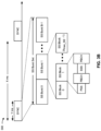
- Controller/processor 240 of base station 110, controller/processor 280 of UE 120, and/or any other component(s) of Fig. 2 may perform one or more techniques associated with indicating a UU capability for cross-link interference (CLI) measurement, as described in more detail elsewhere herein.
- controller/processor 240 of base station 110, controller/processor 280 of UE 120, and/or any other component(s) of Fig. 2 may perform or direct operations of, for example, process 600 of Fig. 6 and/or other processes as described herein.
- Memories 242 and 282 may store data and program codes for base station 110 and UE 120, respectively.
- UE 120 may include means for transmitting a communication that identifies one or more UE capability parameters for at least one of sounding reference signal (SRS) RSRP measurement or CLI RSSI measurement, means for receiving a CLI measurement configuration that is based at least in part on the one or more UE capability parameters, and/or the like.
- such means may include one or more components of UE 120 described in connection with Fig. 2 , such as controller/processor 280, transmit processor 264, TX MIMO processor 266, MOD 254, antenna 252, DEMOD 254, MIMO detector 256, receive processor 258, and/or the like.
- Fig. 2 is provided as an example. Other examples may differ from what is described with regard to Fig. 2 .
- Fig. 3A shows an example frame structure 300 for frequency division duplexing (FDD) in a telecommunications system (e.g., NR).
- the transmission timeline for each of the downlink and uplink may be partitioned into units of radio frames (sometimes referred to as frames).
- Each radio frame may have a predetermined duration (e.g., 10 milliseconds (ms)) and may be partitioned into a set of Z (Z ⁇ 1) subframes (e.g., with indices of 0 through Z-1).
- Each subframe may have a predetermined duration (e.g., 1 ms) and may include a set of slots (e.g., 2 m slots per subframe are shown in Fig.
- Each slot may include a set of L symbol periods.
- each slot may include fourteen symbol periods (e.g., as shown in Fig. 3A ), seven symbol periods, or another number of symbol periods.
- the subframe may include 2L symbol periods, where the 2L symbol periods in each subframe may be assigned indices of 0 through 2L-1.
- a scheduling unit for the FDD may be frame-based, subframe-based, slot-based, symbol-based, and/or the like.
- a wireless communication structure may refer to a periodic time-bounded communication unit defined by a wireless communication standard and/or protocol. Additionally, or alternatively, different configurations of wireless communication structures than those shown in Fig. 3A may be used.
- a base station may transmit synchronization signals.
- a base station may transmit a primary synchronization signal (PSS), a secondary synchronization signal (SSS), and/or the like, on the downlink for each cell supported by the base station.
- PSS and SSS may be used by UEs for cell search and acquisition.
- the PSS may be used by UEs to determine symbol timing
- the SSS may be used by UEs to determine a physical cell identifier, associated with the base station, and frame timing.
- the base station may also transmit a physical broadcast channel (PBCH).
- the PBCH may carry some system information, such as system information that supports initial access by UEs.
- the base station may transmit the PSS, the SSS, and/or the PBCH in accordance with a synchronization communication hierarchy (e.g., a synchronization signal (SS) hierarchy) including multiple synchronization communications (e.g., SS blocks), as described below in connection with Fig. 3B .
- a synchronization communication hierarchy e.g., a synchronization signal (SS) hierarchy
- multiple synchronization communications e.g., SS blocks
- Fig. 3B is a block diagram conceptually illustrating an example SS hierarchy, which is an example of a synchronization communication hierarchy.
- the SS hierarchy may include an SS burst set, which may include a plurality of SS bursts (identified as SS burst 0 through SS burst B-1, where B is a maximum number of repetitions of the SS burst that may be transmitted by the base station).
- each SS burst may include one or more SS blocks (identified as SS block 0 through SS block (b max_SS -1), where b max_SS -1 is a maximum number of SS blocks that can be carried by an SS burst).
- An SS burst set may be periodically transmitted by a wireless node, such as every X milliseconds, as shown in Fig. 3B .
- an SS burst set may have a fixed or dynamic length, shown as Y milliseconds in Fig. 3B .
- the SS burst set shown in Fig. 3B is an example of a synchronization communication set, and other synchronization communication sets may be used in connection with the techniques described herein.
- the SS block shown in Fig. 3B is an example of a synchronization communication, and other synchronization communications may be used in connection with the techniques described herein.
- an SS block includes resources that carry the PSS, the SSS, the PBCH, and/or other synchronization signals (e.g., a tertiary synchronization signal (TSS)) and/or synchronization channels.
- synchronization signals e.g., a tertiary synchronization signal (TSS)
- multiple SS blocks are included in an SS burst, and the PSS, the SSS, and/or the PBCH may be the same across each SS block of the SS burst.
- a single SS block may be included in an SS burst.
- the SS block may be at least four symbol periods in length, where each symbol carries one or more of the PSS (e.g., occupying one symbol), the SSS (e.g., occupying one symbol), and/or the PBCH (e.g., occupying two symbols).
- the symbols of an SS block are consecutive, as shown in Fig. 3B .
- the symbols of an SS block are non-consecutive.
- one or more SS blocks of the SS burst may be transmitted in consecutive radio resources (e.g., consecutive symbol periods) during one or more slots. Additionally, or alternatively, one or more SS blocks of the SS burst may be transmitted in non-consecutive radio resources.
- the SS bursts may have a burst period, whereby the SS blocks of the SS burst are transmitted by the base station according to the burst period. In other words, the SS blocks may be repeated during each SS burst.
- the SS burst set may have a burst set periodicity, whereby the SS bursts of the SS burst set are transmitted by the base station according to the fixed burst set periodicity. In other words, the SS bursts may be repeated during each SS burst set.
- the base station may transmit system information, such as system information blocks (SIBs) on a physical downlink shared channel (PDSCH) in certain slots.
- SIBs system information blocks
- the base station may transmit control information/data on a physical downlink control channel (PDCCH) in C symbol periods of a slot, where B may be configurable for each slot.
- the base station may transmit traffic data and/or other data on the PDSCH in the remaining symbol periods of each slot.
- FIGS. 3A and 3B are provided as examples. Other examples may differ from what is described with regard to Figs. 3A and 3B .
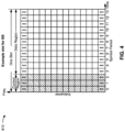
- Fig. 4 shows an example slot format 410 with a normal cyclic prefix.
- the available time frequency resources may be partitioned into resource blocks.
- Each resource block may cover a set of subcarriers (e.g., 12 subcarriers) in one slot and may include a number of resource elements.
- Each resource element may cover one subcarrier in one symbol period (e.g., in time) and may be used to send one modulation symbol, which may be a real or complex value.
- An interlace structure may be used for each of the downlink and uplink for FDD in certain telecommunications systems (e.g., NR).
- Q interlaces with indices of 0 through Q - 1 may be defined, where Q may be equal to 4, 6, 8, 10, or some other value.
- Each interlace may include slots that are spaced apart by Q frames.
- interlace q may include slots q, q + Q, q + 2Q, etc., where q ⁇ 10, ..., Q - 1 ⁇ .
- a UE may be located within the coverage of multiple BSs. One of these BSs may be selected to serve the UE. The serving BS may be selected based at least in part on various criteria such as received signal strength, received signal quality, path loss, and/or the like. Received signal quality may be quantified by a signal-to-noise-and-interference ratio (SNIR), or a reference signal received quality (RSRQ), or some other metric.
- SNIR signal-to-noise-and-interference ratio
- RSRQ reference signal received quality
- the UE may operate in a dominant interference scenario in which the UE may observe high interference from one or more interfering BSs.
- New Radio may refer to radios configured to operate according to a new air interface (e.g., other than Orthogonal Frequency Divisional Multiple Access (OFDMA)-based air interfaces) or fixed transport layer (e.g., other than Internet Protocol (IP)).
- OFDM Orthogonal Frequency Divisional Multiple Access
- IP Internet Protocol
- NR may utilize OFDM with a CP (herein referred to as cyclic prefix OFDM or CP-OFDM) and/or SC-FDM on the uplink, may utilize CP-OFDM on the downlink and include support for half-duplex operation using time division duplexing (TDD).
- OFDM Orthogonal Frequency Divisional Multiple Access
- IP Internet Protocol
- NR may, for example, utilize OFDM with a CP (herein referred to as CP-OFDM) and/or discrete Fourier transform spread orthogonal frequency-division multiplexing (DFT-s-OFDM) on the uplink, may utilize CP-OFDM on the downlink and include support for half-duplex operation using TDD.
- NR may include Enhanced Mobile Broadband (eMBB) service targeting wide bandwidth (e.g., 80 megahertz (MHz) and beyond), millimeter wave (mmW) targeting high carrier frequency (e.g., 60 gigahertz (GHz)), massive MTC (mMTC) targeting non-backward compatible MTC techniques, and/or mission critical targeting ultra reliable low latency communications (URLLC) service.
- eMBB Enhanced Mobile Broadband
- mmW millimeter wave
- mMTC massive MTC
- URLLC ultra reliable low latency communications
- NR resource blocks may span 12 sub-carriers with a sub-carrier bandwidth of 60 or 120 kilohertz (kHz) over a 0.1 millisecond (ms) duration.
- Each radio frame may include 40 slots and may have a length of 10 ms. Consequently, each slot may have a length of 0.25 ms.
- Each slot may indicate a link direction (e.g., DL or UL) for data transmission and the link direction for each slot may be dynamically switched.
- Each slot may include DL/UL data as well as DL/UL control data.
- NR may support a different air interface, other than an OFDM-based interface.
- NR networks may include entities such as central units or distributed units.
- Fig. 4 is provided as an example. Other examples may differ from what is described with regard to Fig. 4 .
- a BS may provide wireless coverage in a cell in a time division multiplexing (TDM) configuration in which time-domain resources (e.g., symbols, slots, and/or the like) of the cell may be divided into uplink resources, downlink resources, and/or the like.
- TDM time division multiplexing
- neighboring cells in the wireless network may be configured with different TDM configurations such that each of the neighboring cells is configured with a different combination of uplink resources and downlink resources.
- Cross-link interference may refer to interference with downlink reception at a first UE in a first cell due to uplink transmission by a second UE in a second cell.
- Cross-link interference may occur, for example, where a downlink resource of the first cell at least partially overlaps in the time-domain with an uplink resource of the second cell and where the first UE and the second UE are located at the cell edge of the respective cells.
- the first UE may be configured to measure the cross-link interference so that results of measurement of the cross-link interference may be used to adjust the transmit power of the second UE to reduce, mitigate, and/or eliminate CLI with downlink reception of the first UE.
- some UEs may be capable of supporting different CLI measurement configurations (e.g., due to different processing, memory, and/or networking capabilities).
- a BS may be unaware of a UE's capability for supporting CLI measurement, in which case the BS may configure the UE with a CLI measurement configuration that the UE may not support.
- a UE may transmit a communication that identifies one or more UE capability parameters that the UE may support for CLI measurement.
- the UE capability parameters may indicate, for example, whether the UE supports CLI measurement of particular types of CLI measurement resources, whether the UE supports different subcarrier spacing (SCS) for CLI measurement, the capability of the UE to perform a particular quantity of CLI measurements across serving cells of the UE, and/or other UE capability parameters for CLI measurement.
- SCS subcarrier spacing
- a serving BS of the UE may receive the communication, may identify the UE capability parameters indicated in the communication, and may generate a CLI measurement configuration based at least in part on the UE capability parameters.
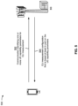
- Fig. 5 is a diagram illustrating one or more examples 500 of indicating a UE capability for CLI measurement, in accordance with the claimed embodiment.
- example(s) 500 may include communication between a BS (e.g., BS 110) and a UE (e.g., UE 120).
- the BS and the UE may be included in a wireless network (e.g., wireless network 100 and/or another wireless network).
- the BS may be a serving BS of the UE, and may generate and transmit a CLI measurement configuration to the UE such that the UE may perform CLI measurement in the wireless network.
- the capability to perform gapless CLI measurements may indicate whether the UE is capable of performing a CLI measurement and receiving a downlink communication (e.g., a physical downlink control channel (PDCCH) communication, a physical downlink shared channel (PDSCH) communication, and/or the like) or transmitting an uplink communication (e.g., a physical uplink control channel (PUCCH), a physical uplink shared channel (PUSCH) communication, and/or the like) in back-to-back OFDM symbols.
- a gapless CLI measurement may include receiving a downlink communication or transmitting an uplink communication in an OFDM symbol and performing a CLI measurement in the next consecutive OFDM symbol.
- the capability to perform gapless CLI measurements may be indicated by one or more bits in the communication.
- the UE capability parameters may include a capability to perform an SRS RSRP measurement when a downlink channel (e.g., PDSCH, PDCCH, and/or the like) of the serving BS or cell is frequency division multiplexed with a CLI measurement resource (e.g., cliMeas-SRS-RSRP-FDMRequired), a capability to perform a CLI RSSI measurement when a downlink channel of the serving BS or cell is frequency division multiplexed with a CLI measurement resource (e.g., cliMeas-CLI-RSSI-FDMRequired, and/or the like), and/or the like.
- a CLI measurement resource e.g., cliMeas-SRS-RSRP-FDMRequired
- the UE capability parameters may indicate a capability to perform an SRS RSRP measurement when an SCS of a CLI measurement resource and an SCS of an active bandwidth part (BWP) associated with the UE are different SCSs (e.g., cliMeas-SRS-RSRP-DifferentSCS), may indicate a capability to perform a CLI RSSI measurement when the SCS of the CLI measurement resource and the SCS of the active BWP associated with the UE are different SCSs (e.g., cliMeas-CLI-RSSI-DifferentSCS), and/or the like.
- SCS active bandwidth part
- the capability to perform an SRS RSRP measurement when an SCS of a CLI measurement resource and an SCS of an active BWP associated with the UE are different SCSs may be indicated by the same bit (or bits) in the communication or by separate bits in the communication.
- the UE may indicate separate capabilities by indicating a capacity or quantity of CLI measurement resources in a same slot that the UE supports for CLI measurement reporting (e.g., beamManagementSSB-CSI-RS-WithCLI-SRS) and indicating separate capacity or quantity of other resources that the UE supports in a same slot for other types of reporting across all serving BSs or cells associated with the UE (e.g., maxNumberSSB-CSI-RS-ResourceOneTx).
- CLI measurement reporting e.g., beamManagementSSB-CSI-RS-WithCLI-SRS
- maxNumberSSB-CSI-RS-ResourceOneTx e.g., maxNumberSSB-CSI-RS-ResourceOneTx
- the UE capability parameters may indicate a capacity or capability to perform a quantity of SRS RSRP measurements in a same slot across all serving BSs or cells associated with the UE (e.g., cliMeas-SRS-RSRP-ResourcesOneTx) and/or a capacity or capability to perform a quantity of SRS RSRP measurements across all serving BSs or cells associated with the UE (e.g., cliMeas-SRS-RSRP-ResourcesTotal).
- the UE capability parameters may indicate a capacity or capability to perform a quantity of CLI RSSI measurements in a same slot across all serving BSs or cells associated with the UE (e.g., cliMeas-CLI-RSSI-ResourcesOneTx) and/or a capacity or capability to perform a quantity of CLI RSSI measurements across all serving BSs or cells associated with the UE (e.g., cliMeas-CLI-RSSI-ResourcesTotal).
- the UE capability parameters may be the same or different for different frequency bands.
- at least a subset of the UE capability parameters may be different for one or more sub-6GHz frequency bands and one or more millimeter wave frequency bands.
- the BS may transmit, to the UE, the CLI measurement configuration for the UE.
- the CLI measurement configuration may be based at least in part on the UE capability parameters for CLI measurement identified in the communication transmitted from the UE to the BS.
- the CLI measurement configuration may identify one or more time-domain and/or frequency-domain resources in which the UE is to perform one or more CLI measurements, the type(s) of CLI measurements that the UE is to perform, the type(s) of CLI measurement resources that the UE is to measure, and/or the like.
- the BS may transmit the CLI measurement configuration to the UE in a downlink control information (DCI) communication, a MAC-CE communication, a radio resource control (RRC) communication, and/or the like.
- DCI downlink control information
- RRC radio resource control
- the UE may transmit a communication that identifies one or more UE capability parameters that the UE may support for CLI measurement.
- the UE capability parameters may indicate, for example, whether the UE supports CLI measurement of particular types of CLI measurement resources, whether the UE supports different SCS for CLI measurement, the capacity or capability of the UE to perform a particular quantity of CLI measurements across serving BSs or cells of the UE, and/or other UE capability parameters for CLI measurement.
- a serving BS of the UE may receive the communication, may identify the UE capability parameters indicated in the communication, and may generate a CLI measurement configuration based at least in part on the UE capability parameters.
- Fig. 5 is provided as one or more examples. Other examples may differ from what is described with respect to Fig. 5 .
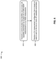
- process 600 may include transmitting a communication that identifies one or more UE capability parameters for at least one of SRS RSRP measurement or CLI RSSI measurement (block 610).
- the UE e.g., using receive processor 258, transmit processor 264, controller/processor 280, memory 282, and/or the like
- process 600 may include receiving a CLI measurement configuration that is based at least in part on the one or more UE capability parameters (block 620).
- the UE e.g., using receive processor 258, transmit processor 264, controller/processor 280, memory 282, and/or the like
- the one or more UE capability parameters include at least one of a capability to perform an SRS RSRP measurement or a capability to perform a CLI RSSI measurement.
- the capability to perform the SRS RSRP measurement is indicated in the communication by a first bit
- the capability to perform the CLI RSSI is indicated in the communication by a second bit.
- the one or more UE capability parameters include a capability to perform gapless CLI measurements.
- the one or more UE capability parameters include at least one of a capability to perform an SRS RSRP measurement when a downlink channel of a serving cell is frequency division multiplexed with a CLI measurement resource or a capability to perform a CLI RSSI measurement when the downlink channel of the serving cell is frequency division multiplexed with the CLI measurement resource.
- the capability to perform the SRS RSRP measurement when the downlink channel of the serving cell is frequency division multiplexed with the CLI measurement resource is indicated in the communication by a first bit
- the capability to perform the CLI RSSI measurement when the downlink channel of the serving cell is frequency division multiplexed with the CLI measurement resource is indicated in the communication by a second bit.
- the capability to perform the SRS RSRP measurement when the downlink channel of the serving cell is frequency division multiplexed with the CLI measurement resource, and the capability to perform the CLI RSSI measurement when the downlink channel of the serving cell is frequency division multiplexed with the CLI measurement resource are indicated in the communication by a same bit.
- the one or more UE capability parameters indicate that the UE is capable of performing gapless CLI measurements, and whether the UE is to receive a downlink channel of a serving cell or a CLI measurement resource if the downlink channel of the serving cell is frequency division multiplexed with the CLI measurement resource.
- the one or more UE capability parameters include at least one of a capability to perform an SRS RSRP measurement when an SCS of a CLI measurement resource and an SCS of an active BWP associated with the UE are different SCSs, or a capability to perform a CLI RSSI measurement when the SCS of the CLI measurement resource and the SCS of the active BWP associated with the UE are different SCSs.
- the capability to perform the SRS RSRP measurement when the SCS of the CLI measurement resource and the SCS of the active BWP associated with the UE are different SCSs is indicated in the communication by a first bit
- the capability to perform the CLI RSSI measurement when the SCS of the CLI measurement resource and the SCS of the active BWP associated with the UE are different SCSs is indicated in the communication by a second bit.
- the one or more UE capability parameters include a quantity of resources that are supported for CLI measurement reporting, CSI-RS measurement reporting, and synchronization signal block measurement reporting in a same slot across all serving cells associated with the UE.
- the one or more UE capability parameters include a quantity of resources that are supported for CLI measurement resources in a same slot across all serving cells associated with the UE.
- the one or more UE capability parameters include a capacity capability to perform a quantity of sounding reference signal reference signal received power measurements in a same slot across all serving cells associated with the UE.
- the one or more UE capability parameters include a capacity capability to perform a quantity of sounding reference signal reference signal received power measurements across all serving cells associated with the UE.
- the one or more UE capability parameters include a capacity capability to perform a quantity of CLI received signal strength indication measurements in a same slot across all serving cells associated with the UE.
- the one or more UE capability parameters include a capacity capability to perform a quantity of CLI received signal strength indication measurements across all serving cells associated with the UE.
- the one or more UE capability parameters are associated with one or more sub-6GHz frequency bands; one or more other UE capability parameters are associated with one or more millimeter wave frequency bands, and at least a subset of the one or more UE capability parameters, and at least a subset of the one or more other UE capability parameters are, different UE capability parameters.
- process 600 may include additional blocks, fewer blocks, different blocks, or differently arranged blocks than those depicted in Fig. 6 . Additionally, or alternatively, two or more of the blocks of process 600 may be performed in parallel.
- ком ⁇ онент is intended to be broadly construed as hardware, firmware, and/or a combination of hardware and software.
- a processor is implemented in hardware, firmware, and/or a combination of hardware and software.
- satisfying a threshold may, depending on the context, refer to a value being greater than the threshold, greater than or equal to the threshold, less than the threshold, less than or equal to the threshold, equal to the threshold, not equal to the threshold, and/or the like.
- "at least one of: a, b, or c” is intended to cover a, b, c, a-b, a-c, b-c, and a-b-c, as well as any combination with multiples of the same element (e.g., a-a, a-a-a, a-a-b, a-a-c, a-b-b, a-c-c, b-b, b-b-b, b-b-c, c-c, and c-c-c or any other ordering of a, b, and c).
Landscapes
- Engineering & Computer Science (AREA)
- Signal Processing (AREA)
- Computer Networks & Wireless Communication (AREA)
- Quality & Reliability (AREA)
- Physics & Mathematics (AREA)
- Electromagnetism (AREA)
- Databases & Information Systems (AREA)
- Power Engineering (AREA)
- Mobile Radio Communication Systems (AREA)
Claims (15)
- Ein Verfahren zur drahtlosen Kommunikation, das von einem Benutzergerät, UE (120), durchgeführt wird, aufweisend:
Übertragen (502, 610) einer Kommunikation an eine Basisstation, BS (110), die eine Vielzahl von UE-Fähigkeiten identifiziert, einschließlich einer ersten UE-Fähigkeit, um eine Messung eines Referenzsignals, SRS, für die Leistung des Referenzsignals, RSRP, durchzuführen, wenn ein Abwärtsverbindungskanal einer bedienenden Zelle mit einer Querverbindungsinterferenz-, CLI, Messressource gemultiplext wird, und eine zweite Fähigkeit des UE, eine Querverbindungsinterferenz-, CLI, Empfangssignalstärkeanzeige-, RSSI, Messung durchzuführen, wenn ein Abwärtsverbindungskanal einer bedienenden Zelle mit einer CLI-Messressource frequenzgemultiplext wird; und Empfangen (504, 620) einer CLI-Messkonfiguration von der BS (110), die zumindest teilweise auf der Vielzahl von UE-Fähigkeiten basiert. - Das Verfahren nach Anspruch 1, wobei die erste Fähigkeit des UE zur Durchführung der SRS-RSRP-Messung in der Kommunikation durch ein erstes Bit angezeigt wird; und
wobei die zweite Fähigkeit des UE zur Durchführung der CLI-RSSI in der Kommunikation durch ein zweites Bit angezeigt wird. - Das Verfahren nach Anspruch 1, wobei die Vielzahl von Fähigkeiten des UE Folgendes umfasst:
eine Fähigkeit des UE zur Durchführung lückenloser CLI-Messungen. - Das Verfahren nach Anspruch 1, wobei die Vielzahl von UE-Fähigkeiten Folgendes anzeigt:dass das UE in der Lage ist, lückenlose CLI-Messungen durchzuführen, undob das UE einen Abwärtsverbindungskanal einer bedienenden Zelle oder eine CLI-Messressource empfangen soll, wenn der Abwärtsverbindungskanal der bedienenden Zelle mit der CLI-Messressource frequenzgemultiplext ist.
- Das Verfahren nach Anspruch 1, wobei die Vielzahl von UE-Fähigkeiten zumindest eines umfasst von:eine Fähigkeit des UE, eine SRS-RSRP-Messung durchzuführen, wenn ein Unterträgerabstand, SCS, einer CLI-Messressource und ein SCS eines aktiven Bandbreitenteils BWP, die mit dem UE verbunden sind, unterschiedliche SCSs sind, odereine Fähigkeit des UE, eine CLI-RSSI-Messung durchzuführen, wenn der SCS der CLI-Messressource und der SCS des aktiven BWP, die mit dem UE verbunden sind, unterschiedliche SCSs sind.
- Das Verfahren nach Anspruch 1, wobei die Vielzahl von UE-Fähigkeiten Folgendes umfasst:eine Menge von Ressourcen, die für CLI-Messberichte, Kanalstatus-Information-Referenz-Signal-, CSI-RS, Messberichte undSynchronisationssignalblock-Messberichte in einem gleichen Slot über alle mit dem UE (120) verbundenen bedienenden Zellen hinweg unterstützt werden.
- Das Verfahren nach Anspruch 1, wobei die Vielzahl von UE-Fähigkeiten Folgendes umfasst:
eine Menge von Ressourcen, die für CLI-Messressourcen in einem gleichen Slot über alle mit dem UE (120) verbundenen bedienenden Zellen unterstützt werden. - Das Verfahren nach Anspruch 1, wobei die Vielzahl von UE-Fähigkeiten Folgendes umfasst:
eine Kapazitätsfähigkeit, eine Menge von SRS-RSRP-Messungen in einem gleichen Slot über alle mit dem UE (120) verbundenen bedienenden Zellen durchzuführen. - Das Verfahren nach Anspruch 1, wobei die Vielzahl von UE-Fähigkeiten Folgendes umfasst:
eine Kapazitätsfähigkeit zur Durchführung einer Menge von SRS-RSRP-Messungen über alle mit dem UE (120) verbundenen bedienenden Zellen. - Das Verfahren nach Anspruch 1, wobei die Vielzahl von UE-Fähigkeiten Folgendes umfasst:
eine Kapazitätsfähigkeit, eine Menge von CLI-RSSI-Messungen in einem gleichen Zeitschlitz über alle mit dem UE (120) verbundenen bedienenden Zellen durchzuführen. - Das Verfahren nach Anspruch 1, wobei die Vielzahl von UE-Fähigkeiten Folgendes umfasst:
eine Kapazitätsfähigkeit, eine Menge von CLI-RSSI-Messungen über alle mit dem UE (120) verbundenen bedienenden Zellen durchzuführen. - Das Verfahren nach Anspruch 1, wobei die Vielzahl von UE-Fähigkeiten mit einem oder mehreren Sub-6-GHz-Frequenzbändern verbunden sind;wobei eine oder mehrere andere UE-Fähigkeiten mit einem oder mehreren Millimeterwellen-Frequenzbändern verbunden sind; undwobei zumindest eine Teilmenge der Vielzahl von UE-Fähigkeiten und zumindest eine Teilmenge der einen oder mehreren anderen UE-Fähigkeiten unterschiedliche UE-Fähigkeiten sind.
- Ein Benutzergerät, UE, für drahtlose Kommunikation, aufweisend:Mittel zum Übertragen einer Kommunikation an eine Basisstation, BS (110), die eine Vielzahl von Fähigkeiten vom Benutzergerät, UE, identifiziert,einschließlich einer ersten UE-Fähigkeit, eine Messung eines Referenzsignals, SRS, für die Leistung des Referenzsignals, RSRP, durchzuführen, wenn ein Abwärtsverbindungskanal einer bedienenden Zelle mit einer Querverbindungsinterferenz-, CLI, Messressource gemultiplext wird, und eine zweite Fähigkeit des UE, eine Querverbindungsinterferenz-, CLI, Empfangssignalstärkeanzeige-, RSSI, Messung durchzuführen, wenn ein Abwärtsverbindungskanal einer bedienenden Zelle mit einer CLI-Messressource frequenzgemultiplext wird; undMittel zum Empfangen einer CLI-Messkonfiguration von der BS (110), die zumindest teilweise auf der Vielzahl von UE-Fähigkeiten basiert.
- Das Benutzergerät, UE, nach Anspruch 13, wobei die Vielzahl von UE-Fähigkeiten Folgendes umfasst:eine Kapazitätsfähigkeit, eine Menge von SRS-RSRP-Messungen über alle mit der Vorrichtung verbundenen bedienenden Zellen durchzuführen; odereine Kapazitätsfähigkeit, eine Menge von CLI-RSSI-Messungen über alle mit dem Benutzergerät verbundenen bedienenden Zellen durchzuführen.
- Ein Computerprogrammprodukt, das Folgendes aufweist:
ein computerlesbares Medium, das einen Programmcode aufweist, der einen Prozessor eines Benutzergeräts, UE (120), veranlasst, das Verfahren gemäß einem der Ansprüche 1 bis 12 auszuführen, wenn es ausgeführt wird.
Applications Claiming Priority (3)
| Application Number | Priority Date | Filing Date | Title |
|---|---|---|---|
| US201962891726P | 2019-08-26 | 2019-08-26 | |
| US16/947,925 US11683709B2 (en) | 2019-08-26 | 2020-08-24 | Indicating a user equipment capability for crosslink interference measurement |
| PCT/US2020/070459 WO2021042123A1 (en) | 2019-08-26 | 2020-08-25 | Indicating a user equipment capability for cross-link interference measurement |
Publications (2)
| Publication Number | Publication Date |
|---|---|
| EP4022951A1 EP4022951A1 (de) | 2022-07-06 |
| EP4022951B1 true EP4022951B1 (de) | 2024-11-27 |
Family
ID=74682017
Family Applications (1)
| Application Number | Title | Priority Date | Filing Date |
|---|---|---|---|
| EP20767702.2A Active EP4022951B1 (de) | 2019-08-26 | 2020-08-25 | Anzeige einer benutzergerätefähigkeit für verbundungsübergreifende interferenzmessung |
Country Status (4)
| Country | Link |
|---|---|
| US (1) | US11683709B2 (de) |
| EP (1) | EP4022951B1 (de) |
| CN (1) | CN114616857A (de) |
| WO (1) | WO2021042123A1 (de) |
Families Citing this family (28)
| Publication number | Priority date | Publication date | Assignee | Title |
|---|---|---|---|---|
| US12245065B2 (en) * | 2019-02-04 | 2025-03-04 | Apple Inc. | Cross-link interference (CLI) measurement reporting |
| CN113170340A (zh) * | 2019-11-06 | 2021-07-23 | Oppo广东移动通信有限公司 | 无线通信方法、终端设备和网络设备 |
| CN113259076B (zh) * | 2020-02-12 | 2022-08-05 | 大唐移动通信设备有限公司 | 一种信息传输方法、装置及设备 |
| US12063538B2 (en) * | 2020-09-23 | 2024-08-13 | Qualcomm Incorporated | Measurement report for mixed downlink reference signal reporting |
| CN117063514A (zh) | 2021-03-31 | 2023-11-14 | 高通股份有限公司 | 管理下行链路业务接收和交叉链路干扰 |
| US11990762B2 (en) | 2021-05-26 | 2024-05-21 | Qualcomm Incorporated | Channel reporting for energy harvesting at a device |
| US12040630B2 (en) * | 2021-05-26 | 2024-07-16 | Qualcomm Incorporated | Signaling for energy harvesting at a device |
| KR20220161089A (ko) * | 2021-05-28 | 2022-12-06 | 삼성전자주식회사 | 무선 통신 시스템에서 간섭 신호 측정 및 보고를 위한 방법 및 장치 |
| EP4349112A1 (de) * | 2021-06-04 | 2024-04-10 | Qualcomm Incorporated | Verfahren zur priorisierung von querverbindungsinterferenzmessungen |
| WO2023044598A1 (en) * | 2021-09-21 | 2023-03-30 | Qualcomm Incorporated | Systems and methods for managing uplink transmission and crosslink interference measurement |
| US11902816B2 (en) * | 2021-10-12 | 2024-02-13 | Qualcomm Incorporated | Adaptive cross-link interference measurement and reporting framework |
| CN116636250B (zh) * | 2021-12-20 | 2026-02-10 | 北京小米移动软件有限公司 | 一种测量方法、装置、设备及可读存储介质 |
| US12452716B2 (en) * | 2022-04-07 | 2025-10-21 | Qualcomm Incorporated | Techniques for CLI reporting trigger conditions |
| US12302151B2 (en) * | 2022-04-07 | 2025-05-13 | Qualcomm Incorporated | User equipment processing capability aspects for cross-link interference measurement |
| US20230354073A1 (en) * | 2022-04-28 | 2023-11-02 | Qualcomm Incorporated | Cross-link interference reporting on physical uplink channels |
| US12425900B2 (en) | 2022-04-29 | 2025-09-23 | Qualcomm Incorporated | Cross-link interference reporting configuration and payload design |
| US12483917B2 (en) * | 2022-04-29 | 2025-11-25 | Qualcomm Incorporated | Prioritization and timing for cross-link interference reporting |
| US12388508B2 (en) | 2022-05-09 | 2025-08-12 | Qualcomm Incorporated | CPU, timing, and capability specifications for eCSF report based on projected CLI in FD |
| EP4525507A4 (de) * | 2022-05-09 | 2025-07-23 | Beijing Xiaomi Mobile Software Co Ltd | Ressourcenkonfigurationsverfahren und -vorrichtung sowie benutzergerät, netzwerkseitige vorrichtung und speichermedium |
| US20250274790A1 (en) * | 2022-05-19 | 2025-08-28 | Qualcomm Incorporated | Performing cross-link interference measurements in a full-duplex communication mode |
| CN117499971A (zh) * | 2022-07-22 | 2024-02-02 | 北京紫光展锐通信技术有限公司 | 干扰测量的方法、装置、芯片、芯片模组及存储介质 |
| US20240049022A1 (en) * | 2022-07-29 | 2024-02-08 | Qualcomm Incorporated | L1 activation and adaptation of l2 cli reporting |
| WO2024036592A1 (en) * | 2022-08-19 | 2024-02-22 | Qualcomm Incorporated | Medium access control control element for reporting interference |
| WO2024060175A1 (en) * | 2022-09-23 | 2024-03-28 | Qualcomm Incorporated | Timing for cross-link interference reporting |
| US20240147278A1 (en) * | 2022-10-31 | 2024-05-02 | Qualcomm Incorporated | Joint activation of cross-link interference measurement and reporting |
| WO2024092490A1 (en) * | 2022-11-01 | 2024-05-10 | Qualcomm Incorporated | Concurrent measurement gaps for layer one inter-frequency measurements |
| US20240421922A1 (en) * | 2023-06-17 | 2024-12-19 | Qualcomm Incorporated | Cross link interference resource capability |
| US20250030493A1 (en) * | 2023-07-20 | 2025-01-23 | Qualcomm Incorporated | Techniques for wideband interference measurements |
Family Cites Families (8)
| Publication number | Priority date | Publication date | Assignee | Title |
|---|---|---|---|---|
| CN109088683B (zh) * | 2017-06-14 | 2020-12-29 | 中国移动通信有限公司研究院 | 一种用户终端间交叉链路干扰测量的方法、用户终端和传输接收点 |
| CN110190941B (zh) * | 2018-01-12 | 2022-05-10 | 华为技术有限公司 | 一种用于终端设备能力传输的方法、装置及系统 |
| KR102509033B1 (ko) * | 2018-05-10 | 2023-03-09 | 삼성전자주식회사 | 무선 통신 시스템에서 채널 접속 방법 및 장치 |
| WO2020019136A1 (en) * | 2018-07-23 | 2020-01-30 | Qualcomm Incorporated | Configuration of sounding reference signal resource for multi-panel uplink transmission |
| CN117202164A (zh) * | 2019-06-13 | 2023-12-08 | 苹果公司 | Cli测量的rrm测量限制 |
| WO2021000303A1 (en) * | 2019-07-03 | 2021-01-07 | Nokia Shanghai Bell Co., Ltd. | Cross link interference measurement conditions reporting |
| KR20210004447A (ko) * | 2019-07-04 | 2021-01-13 | 삼성전자주식회사 | 차세대 이동 통신 시스템에서 교차 링크 간섭에 대한 측정과 보고 방법 및 장치 |
| US11395171B2 (en) * | 2019-07-19 | 2022-07-19 | Lg Electronics Inc. | Interference measurement |
-
2020
- 2020-08-24 US US16/947,925 patent/US11683709B2/en active Active
- 2020-08-25 WO PCT/US2020/070459 patent/WO2021042123A1/en not_active Ceased
- 2020-08-25 CN CN202080058943.3A patent/CN114616857A/zh active Pending
- 2020-08-25 EP EP20767702.2A patent/EP4022951B1/de active Active
Also Published As
| Publication number | Publication date |
|---|---|
| US20210067991A1 (en) | 2021-03-04 |
| EP4022951A1 (de) | 2022-07-06 |
| CN114616857A (zh) | 2022-06-10 |
| WO2021042123A1 (en) | 2021-03-04 |
| US11683709B2 (en) | 2023-06-20 |
Similar Documents
| Publication | Publication Date | Title |
|---|---|---|
| EP4022951B1 (de) | Anzeige einer benutzergerätefähigkeit für verbundungsübergreifende interferenzmessung | |
| US11290174B2 (en) | Beam selection for communication in a multi-transmit-receive point deployment | |
| EP4038746B1 (de) | Strahlauswahl für kommunikation beim einsatz eines multisendeempfangspunktes | |
| US11368956B2 (en) | Radio link management under bandwidth part switching | |
| EP3931990B1 (de) | Verfahren und vorrichtung zur vernetzungsinterferenzmessung und -meldung | |
| AU2019221649B2 (en) | Physical resource block bundle size selection | |
| US11425702B2 (en) | Repetition configuration determination | |
| EP3782313B1 (de) | En-dc-zeitmultiplex- und trägeraggregation | |
| EP3881476B1 (de) | Quasi-kollokationsrelationkonfiguration für periodische kanalzustandsformationsreferenzsignale | |
| EP3841817B1 (de) | Kollisionshandhabung für eine physikalische uplink-kanalwiederholung | |
| EP3884722B1 (de) | Konfigurieren von kanalzustandsinformationsreferenzsignalteilbandvorcodierungsressourcenblockgruppen | |
| EP3858036B1 (de) | Konfigurieren einer aggregationsebene und von physikalischen downlink-steuerkanalkandidaten an einem benutzergerät | |
| EP4055902A1 (de) | Stromeinsparung basierend auf einer kombinierten zeitangabe und eingestellte suchraumgruppenangabe | |
| CN113647028B (zh) | 用于利用配置的准许的物理上行链路共享信道的探测参考信号资源确定 | |
| US10886995B2 (en) | Beam management signaling | |
| US20200266951A1 (en) | Techniques for shared radio frequency spectrum channel configuration | |
| EP3811712B1 (de) | Kollisionsverwaltung | |
| WO2020061938A1 (en) | Channel state information reporting | |
| WO2021142762A1 (en) | Hopping pattern for cross bandwidth part frequency hopping | |
| WO2020258132A1 (en) | Csi reporting for partial reciprocity | |
| WO2019200608A1 (en) | Techniques and apparatuses for numerology signaling |
Legal Events
| Date | Code | Title | Description |
|---|---|---|---|
| STAA | Information on the status of an ep patent application or granted ep patent |
Free format text: STATUS: UNKNOWN |
|
| STAA | Information on the status of an ep patent application or granted ep patent |
Free format text: STATUS: THE INTERNATIONAL PUBLICATION HAS BEEN MADE |
|
| PUAI | Public reference made under article 153(3) epc to a published international application that has entered the european phase |
Free format text: ORIGINAL CODE: 0009012 |
|
| STAA | Information on the status of an ep patent application or granted ep patent |
Free format text: STATUS: REQUEST FOR EXAMINATION WAS MADE |
|
| 17P | Request for examination filed |
Effective date: 20220127 |
|
| AK | Designated contracting states |
Kind code of ref document: A1 Designated state(s): AL AT BE BG CH CY CZ DE DK EE ES FI FR GB GR HR HU IE IS IT LI LT LU LV MC MK MT NL NO PL PT RO RS SE SI SK SM TR |
|
| DAV | Request for validation of the european patent (deleted) | ||
| DAX | Request for extension of the european patent (deleted) | ||
| GRAP | Despatch of communication of intention to grant a patent |
Free format text: ORIGINAL CODE: EPIDOSNIGR1 |
|
| STAA | Information on the status of an ep patent application or granted ep patent |
Free format text: STATUS: GRANT OF PATENT IS INTENDED |
|
| RIC1 | Information provided on ipc code assigned before grant |
Ipc: H04B 17/345 20150101ALN20240704BHEP Ipc: H04B 17/318 20150101ALN20240704BHEP Ipc: H04L 5/00 20060101ALN20240704BHEP Ipc: H04W 56/00 20090101ALN20240704BHEP Ipc: H04W 24/08 20090101ALN20240704BHEP Ipc: H04W 8/24 20090101AFI20240704BHEP |
|
| INTG | Intention to grant announced |
Effective date: 20240722 |
|
| RIC1 | Information provided on ipc code assigned before grant |
Ipc: H04B 17/345 20150101ALN20240712BHEP Ipc: H04B 17/318 20150101ALN20240712BHEP Ipc: H04L 5/00 20060101ALN20240712BHEP Ipc: H04W 56/00 20090101ALN20240712BHEP Ipc: H04W 24/08 20090101ALN20240712BHEP Ipc: H04W 8/24 20090101AFI20240712BHEP |
|
| GRAS | Grant fee paid |
Free format text: ORIGINAL CODE: EPIDOSNIGR3 |
|
| GRAA | (expected) grant |
Free format text: ORIGINAL CODE: 0009210 |
|
| STAA | Information on the status of an ep patent application or granted ep patent |
Free format text: STATUS: THE PATENT HAS BEEN GRANTED |
|
| AK | Designated contracting states |
Kind code of ref document: B1 Designated state(s): AL AT BE BG CH CY CZ DE DK EE ES FI FR GB GR HR HU IE IS IT LI LT LU LV MC MK MT NL NO PL PT RO RS SE SI SK SM TR |
|
| REG | Reference to a national code |
Ref country code: GB Ref legal event code: FG4D |
|
| REG | Reference to a national code |
Ref country code: CH Ref legal event code: EP |
|
| REG | Reference to a national code |
Ref country code: IE Ref legal event code: FG4D |
|
| REG | Reference to a national code |
Ref country code: DE Ref legal event code: R096 Ref document number: 602020042096 Country of ref document: DE |
|
| REG | Reference to a national code |
Ref country code: LT Ref legal event code: MG9D |
|
| REG | Reference to a national code |
Ref country code: NL Ref legal event code: MP Effective date: 20241127 |
|
| PG25 | Lapsed in a contracting state [announced via postgrant information from national office to epo] |
Ref country code: PT Free format text: LAPSE BECAUSE OF FAILURE TO SUBMIT A TRANSLATION OF THE DESCRIPTION OR TO PAY THE FEE WITHIN THE PRESCRIBED TIME-LIMIT Effective date: 20250327 Ref country code: IS Free format text: LAPSE BECAUSE OF FAILURE TO SUBMIT A TRANSLATION OF THE DESCRIPTION OR TO PAY THE FEE WITHIN THE PRESCRIBED TIME-LIMIT Effective date: 20250327 Ref country code: HR Free format text: LAPSE BECAUSE OF FAILURE TO SUBMIT A TRANSLATION OF THE DESCRIPTION OR TO PAY THE FEE WITHIN THE PRESCRIBED TIME-LIMIT Effective date: 20241127 |
|
| PG25 | Lapsed in a contracting state [announced via postgrant information from national office to epo] |
Ref country code: NL Free format text: LAPSE BECAUSE OF FAILURE TO SUBMIT A TRANSLATION OF THE DESCRIPTION OR TO PAY THE FEE WITHIN THE PRESCRIBED TIME-LIMIT Effective date: 20241127 Ref country code: FI Free format text: LAPSE BECAUSE OF FAILURE TO SUBMIT A TRANSLATION OF THE DESCRIPTION OR TO PAY THE FEE WITHIN THE PRESCRIBED TIME-LIMIT Effective date: 20241127 |
|
| REG | Reference to a national code |
Ref country code: AT Ref legal event code: MK05 Ref document number: 1746944 Country of ref document: AT Kind code of ref document: T Effective date: 20241127 |
|
| PG25 | Lapsed in a contracting state [announced via postgrant information from national office to epo] |
Ref country code: BG Free format text: LAPSE BECAUSE OF FAILURE TO SUBMIT A TRANSLATION OF THE DESCRIPTION OR TO PAY THE FEE WITHIN THE PRESCRIBED TIME-LIMIT Effective date: 20241127 |
|
| PG25 | Lapsed in a contracting state [announced via postgrant information from national office to epo] |
Ref country code: ES Free format text: LAPSE BECAUSE OF FAILURE TO SUBMIT A TRANSLATION OF THE DESCRIPTION OR TO PAY THE FEE WITHIN THE PRESCRIBED TIME-LIMIT Effective date: 20241127 |
|
| PG25 | Lapsed in a contracting state [announced via postgrant information from national office to epo] |
Ref country code: NO Free format text: LAPSE BECAUSE OF FAILURE TO SUBMIT A TRANSLATION OF THE DESCRIPTION OR TO PAY THE FEE WITHIN THE PRESCRIBED TIME-LIMIT Effective date: 20250227 |
|
| PG25 | Lapsed in a contracting state [announced via postgrant information from national office to epo] |
Ref country code: GR Free format text: LAPSE BECAUSE OF FAILURE TO SUBMIT A TRANSLATION OF THE DESCRIPTION OR TO PAY THE FEE WITHIN THE PRESCRIBED TIME-LIMIT Effective date: 20250228 Ref country code: AT Free format text: LAPSE BECAUSE OF FAILURE TO SUBMIT A TRANSLATION OF THE DESCRIPTION OR TO PAY THE FEE WITHIN THE PRESCRIBED TIME-LIMIT Effective date: 20241127 Ref country code: LV Free format text: LAPSE BECAUSE OF FAILURE TO SUBMIT A TRANSLATION OF THE DESCRIPTION OR TO PAY THE FEE WITHIN THE PRESCRIBED TIME-LIMIT Effective date: 20241127 |
|
| PG25 | Lapsed in a contracting state [announced via postgrant information from national office to epo] |
Ref country code: PL Free format text: LAPSE BECAUSE OF FAILURE TO SUBMIT A TRANSLATION OF THE DESCRIPTION OR TO PAY THE FEE WITHIN THE PRESCRIBED TIME-LIMIT Effective date: 20241127 |
|
| PG25 | Lapsed in a contracting state [announced via postgrant information from national office to epo] |
Ref country code: RS Free format text: LAPSE BECAUSE OF FAILURE TO SUBMIT A TRANSLATION OF THE DESCRIPTION OR TO PAY THE FEE WITHIN THE PRESCRIBED TIME-LIMIT Effective date: 20250227 |
|
| PG25 | Lapsed in a contracting state [announced via postgrant information from national office to epo] |
Ref country code: SM Free format text: LAPSE BECAUSE OF FAILURE TO SUBMIT A TRANSLATION OF THE DESCRIPTION OR TO PAY THE FEE WITHIN THE PRESCRIBED TIME-LIMIT Effective date: 20241127 |
|
| PG25 | Lapsed in a contracting state [announced via postgrant information from national office to epo] |
Ref country code: DK Free format text: LAPSE BECAUSE OF FAILURE TO SUBMIT A TRANSLATION OF THE DESCRIPTION OR TO PAY THE FEE WITHIN THE PRESCRIBED TIME-LIMIT Effective date: 20241127 |
|
| PG25 | Lapsed in a contracting state [announced via postgrant information from national office to epo] |
Ref country code: EE Free format text: LAPSE BECAUSE OF FAILURE TO SUBMIT A TRANSLATION OF THE DESCRIPTION OR TO PAY THE FEE WITHIN THE PRESCRIBED TIME-LIMIT Effective date: 20241127 |
|
| PG25 | Lapsed in a contracting state [announced via postgrant information from national office to epo] |
Ref country code: RO Free format text: LAPSE BECAUSE OF FAILURE TO SUBMIT A TRANSLATION OF THE DESCRIPTION OR TO PAY THE FEE WITHIN THE PRESCRIBED TIME-LIMIT Effective date: 20241127 |
|
| PG25 | Lapsed in a contracting state [announced via postgrant information from national office to epo] |
Ref country code: SK Free format text: LAPSE BECAUSE OF FAILURE TO SUBMIT A TRANSLATION OF THE DESCRIPTION OR TO PAY THE FEE WITHIN THE PRESCRIBED TIME-LIMIT Effective date: 20241127 |
|
| PG25 | Lapsed in a contracting state [announced via postgrant information from national office to epo] |
Ref country code: CZ Free format text: LAPSE BECAUSE OF FAILURE TO SUBMIT A TRANSLATION OF THE DESCRIPTION OR TO PAY THE FEE WITHIN THE PRESCRIBED TIME-LIMIT Effective date: 20241127 |
|
| PG25 | Lapsed in a contracting state [announced via postgrant information from national office to epo] |
Ref country code: IT Free format text: LAPSE BECAUSE OF FAILURE TO SUBMIT A TRANSLATION OF THE DESCRIPTION OR TO PAY THE FEE WITHIN THE PRESCRIBED TIME-LIMIT Effective date: 20241127 |
|
| REG | Reference to a national code |
Ref country code: DE Ref legal event code: R097 Ref document number: 602020042096 Country of ref document: DE |
|
| PG25 | Lapsed in a contracting state [announced via postgrant information from national office to epo] |
Ref country code: SE Free format text: LAPSE BECAUSE OF FAILURE TO SUBMIT A TRANSLATION OF THE DESCRIPTION OR TO PAY THE FEE WITHIN THE PRESCRIBED TIME-LIMIT Effective date: 20241127 |
|
| PLBE | No opposition filed within time limit |
Free format text: ORIGINAL CODE: 0009261 |
|
| STAA | Information on the status of an ep patent application or granted ep patent |
Free format text: STATUS: NO OPPOSITION FILED WITHIN TIME LIMIT |
|
| PGFP | Annual fee paid to national office [announced via postgrant information from national office to epo] |
Ref country code: DE Payment date: 20250709 Year of fee payment: 6 |
|
| PGFP | Annual fee paid to national office [announced via postgrant information from national office to epo] |
Ref country code: GB Payment date: 20250710 Year of fee payment: 6 |
|
| PGFP | Annual fee paid to national office [announced via postgrant information from national office to epo] |
Ref country code: FR Payment date: 20250709 Year of fee payment: 6 |
|
| 26N | No opposition filed |
Effective date: 20250828 |