EP4022280B1 - Verfahren und vorrichtung zur optischen charakterisierung von partikeln - Google Patents
Verfahren und vorrichtung zur optischen charakterisierung von partikeln Download PDFInfo
- Publication number
- EP4022280B1 EP4022280B1 EP20771211.8A EP20771211A EP4022280B1 EP 4022280 B1 EP4022280 B1 EP 4022280B1 EP 20771211 A EP20771211 A EP 20771211A EP 4022280 B1 EP4022280 B1 EP 4022280B1
- Authority
- EP
- European Patent Office
- Prior art keywords
- particle
- image
- sample
- optical
- target molecule
- Prior art date
- Legal status (The legal status is an assumption and is not a legal conclusion. Google has not performed a legal analysis and makes no representation as to the accuracy of the status listed.)
- Active
Links
Images



Classifications
-
- G—PHYSICS
- G01—MEASURING; TESTING
- G01N—INVESTIGATING OR ANALYSING MATERIALS BY DETERMINING THEIR CHEMICAL OR PHYSICAL PROPERTIES
- G01N15/00—Investigating characteristics of particles; Investigating permeability, pore-volume or surface-area of porous materials
- G01N15/02—Investigating particle size or size distribution
- G01N15/0205—Investigating particle size or size distribution by optical means
- G01N15/0227—Investigating particle size or size distribution by optical means using imaging; using holography
-
- G—PHYSICS
- G01—MEASURING; TESTING
- G01N—INVESTIGATING OR ANALYSING MATERIALS BY DETERMINING THEIR CHEMICAL OR PHYSICAL PROPERTIES
- G01N15/00—Investigating characteristics of particles; Investigating permeability, pore-volume or surface-area of porous materials
- G01N15/02—Investigating particle size or size distribution
- G01N15/0205—Investigating particle size or size distribution by optical means
-
- G—PHYSICS
- G01—MEASURING; TESTING
- G01N—INVESTIGATING OR ANALYSING MATERIALS BY DETERMINING THEIR CHEMICAL OR PHYSICAL PROPERTIES
- G01N15/00—Investigating characteristics of particles; Investigating permeability, pore-volume or surface-area of porous materials
- G01N15/10—Investigating individual particles
- G01N15/14—Optical investigation techniques, e.g. flow cytometry
- G01N15/1468—Optical investigation techniques, e.g. flow cytometry with spatial resolution of the texture or inner structure of the particle
-
- G—PHYSICS
- G02—OPTICS
- G02B—OPTICAL ELEMENTS, SYSTEMS OR APPARATUS
- G02B21/00—Microscopes
- G02B21/06—Means for illuminating specimens
-
- G—PHYSICS
- G02—OPTICS
- G02B—OPTICAL ELEMENTS, SYSTEMS OR APPARATUS
- G02B21/00—Microscopes
- G02B21/36—Microscopes arranged for photographic purposes or projection purposes or digital imaging or video purposes including associated control and data processing arrangements
- G02B21/365—Control or image processing arrangements for digital or video microscopes
- G02B21/367—Control or image processing arrangements for digital or video microscopes providing an output produced by processing a plurality of individual source images, e.g. image tiling, montage, composite images, depth sectioning, image comparison
-
- G—PHYSICS
- G01—MEASURING; TESTING
- G01N—INVESTIGATING OR ANALYSING MATERIALS BY DETERMINING THEIR CHEMICAL OR PHYSICAL PROPERTIES
- G01N15/00—Investigating characteristics of particles; Investigating permeability, pore-volume or surface-area of porous materials
- G01N2015/0042—Investigating dispersion of solids
- G01N2015/0053—Investigating dispersion of solids in liquids, e.g. trouble
-
- G—PHYSICS
- G01—MEASURING; TESTING
- G01N—INVESTIGATING OR ANALYSING MATERIALS BY DETERMINING THEIR CHEMICAL OR PHYSICAL PROPERTIES
- G01N15/00—Investigating characteristics of particles; Investigating permeability, pore-volume or surface-area of porous materials
- G01N15/10—Investigating individual particles
- G01N15/14—Optical investigation techniques, e.g. flow cytometry
- G01N15/1434—Optical arrangements
- G01N2015/1454—Optical arrangements using phase shift or interference, e.g. for improving contrast
Definitions
- Some particles such as metallic nanoparticles (NPs) exhibit localized plasmon resonance effects around the visible/infrared range and have been widely studied for nanophotonic applications such as light confinement or heat generation at the nanoscale for applications in catalysis, biomedicine or biosensing.
- NPs metallic nanoparticles
- alternative materials for particles have been proposed, whether for plasmonics or for the study of Mie resonances. These materials include, for example, alloys, semiconductor materials, oxides, nitrides and dielectrics.
- NPs gold nanoparticles
- the optical characterization of NPs generally consists of measuring an extinction cross section, as described for example in the article by A. Arbouet et al. [Ref. 1].
- measuring complex polarizability can provide all the information related to the optical properties of a particle. Moreover, it quantifies not only the amplitude of the electron oscillation in the particle, but also the phase of the oscillation, an important physical quantity in plasmonics.
- the method according to the first aspect of the present invention allows for example the quantitative determination of the complex dipolar optical polarizability of at least one particle present in a sample.
- the particle is a nanoparticle (NP) or a microparticle.
- NP nanoparticle
- all the dimensions of the particle can be between 10 nm and 500 nm.
- the particle is of a biological nature (plant, animal, prokaryotic, eukaryotic, unicellular, multicellular) or inert (metallic, dielectric, mineral, semiconductor).
- the particle can be a living organism, such as a bacteria, or an inert object, such as a metallic particle such as a gold nanoparticle.
- the particle is a wire, i.e. an object confined in only two directions of space.
- the wire may have a diameter of 100 nm and be 1 mm long.
- the method according to the first aspect may be applied to isolated and/or grouped particles to form, for example, an agglomerate or a regular or irregular network of particles.
- the at least one particle is present in the sample in the form of a suspension or deposited on a substrate, such as a glass slide.
- the sample comprises a plurality of particles, some of which are present in the form of a suspension and others of which are deposited on a substrate.
- phase image and intensity image we mean a two-dimensional spatial distribution respectively of the phase and intensity of the electromagnetic field in said analysis plane.
- the phase of the electromagnetic field at a point on the analysis plane is understood in the broad sense in this description and generally includes any quantity proportional to the optical path difference (or "ddm", or OPD, according to the English term, for Optical Path Difference) experienced by a ray transmitted or reflected by the sample and incident at said point in the presence of the characterized particle, compared to the case where the particle is absent.
- the phase can relate to a quantity proportional to the local gradient of the optical wavefront.
- polarizability in the claims and description is meant the complex dipole optical polarizability.
- determining the complex dipole optical polarizability includes determining at least one of the real part, the argument, the norm, or the imaginary part of the complex polarizability of the at least one particle.
- the polarizability is a scalar defined by equation (1), and may be a complex number. Measuring a single scalar for the polarizability may be suitable for example for isotropic particles.
- the particle considered is not isotropic and the method according to the first aspect aims to determine a dipolar optical polarizability tensor.
- the method according to the first aspect may then comprise the determination of as many scalar measurements as there are components in the tensor. Such components of the polarizability tensor are associated with dimensions of the space in which the polarizability of the particle is considered.
- the components of the tensor can be measured by the method, by varying the orientation of the linear polarization of the light beam illuminating the sample via a polarizer (polarizer in illumination), and by varying the orientation of a linear polarizer placed between the sample and the image space of the optical system (polarizer in detection), for example just upstream of the image space of the optical system.
- polarizer polarizer in illumination
- polarizer in detection varying the orientation of a linear polarizer placed between the sample and the image space of the optical system
- the method according to the first aspect comprises the orientation of the two polarizers (in illumination and detection) along the same direction x (resp. y ), and the determination of the polarizability under this condition.
- the sample is illuminated with x -polarized light (resp. y )
- the detecting polarizer is oriented in the other direction y (resp. x ), and the polarizability is determined under this condition.
- the method comprises acquiring a phase image and an intensity image simultaneously.
- Such simultaneity may, for example, make it possible to accelerate the measurement time of the method according to the first aspect, and may prove practical in the case of particles whose optical properties evolve over time.
- the simultaneous acquisition of at least one phase image and at least one intensity image is carried out by multilateral shift interferometry, for example quadrilateral shift interferometry.
- Multilateral shift interferometry allows, in a single measurement, a quantitative determination of the phase and the intensity with high resolution and high sensitivity.
- the acquisition of at least one phase image and at least one intensity image may not be simultaneous.
- the optical property of the particle varies little or not at all over time, such simultaneity is not required.
- the acquisition of at least one phase image and at least one intensity image is carried out by "off-axis” holographic microscopy (DHM for Digital Holographic Microscopy, Hilbert Phase Microscopy, ) or “common path” (Fourier Phase Microscopy, Diffraction Phase Microscopy), by "phase-shifting interferometry", or by means of a non-interferometric technique based on the intensity transport equation
- the optical system operates in transmission. According to one or more exemplary embodiments, the optical system operates in reflection.
- the illumination of the sample is at least partially spatially coherent and obtained from a non-coherent light source, for example an LED, a filament lamp, a laser-sustained plasma lamp (LDLS).
- a non-coherent light source for example an LED, a filament lamp, a laser-sustained plasma lamp (LDLS).
- LDLS laser-sustained plasma lamp
- a device allowing the adjustment of the numerical aperture of the illumination can for example contribute to varying the degree of spatial coherence of the illumination.
- the illumination comprises Köhler illumination.
- the determination of the optical property comprises a processing carried out from said at least one phase and intensity image.
- Said processing comprises calculating, from said at least one phase image and said at least one intensity image, a combined image, said combined image (or "combination image") being obtained from the normalized complex transmission, the real part of the normalized complex transmission or the imaginary part of the normalized complex transmission.
- the processing also comprises the summation of points (or "pixels") of said combined image in a given field of the image comprising an image of said at least one particle.
- the combination image may comprise Airy spots, corresponding to the detection of as many particles present in the sample.
- the summation of pixels is carried out on a restricted area of the combination image, comprising for example an Airy spot corresponding to the image of a particle, for example the minimum area making it possible to cover all of the diffraction rings of the Airy spot.
- the method can provide an accurate determination of at least one optical property.
- the summation is performed over an area containing several Airy spots corresponding to as many particles, then the set of said particles can be considered as a multiple system.
- the method allows the determination of the polarizability and cross sections of such a multiple system, because the polarizability and cross sections are additive.
- the method further comprises varying the numerical aperture of said optical system and acquiring a plurality of intensity images and/or phase images at different numerical apertures.
- the optical system may comprise an iris, the rotation of which makes it possible to vary the numerical aperture of the optical system.
- Acquiring intensity and phase images at different numerical apertures and averaging them makes it possible to reduce the spatial extension of the diffraction rings of an Airy spot, and therefore to integrate an area of the image (e.g., by performing a summation of pixels of the image) comprising the less spread Airy spot, and thus to gain in signal-to-noise ratio. This may for example make it possible to study particles very close to each other and comprising Airy rings which would overlap without such averaging.
- a gain of N can be obtained in the signal-to-noise ratio, where N is the number of combination images produced at different numerical apertures.
- the analysis plane is optically conjugated with the sample plane.
- defocusing i.e. a measurement in a plane that deviates from the plane conjugated with the sample plane, does not affect the accuracy of the measurement, since the applicants have shown that the measured value of optical properties such as ⁇ - polarizability and cross sections is independent of the focus.
- a change of focus is synonymous with a defocusing with respect to a configuration in which a plane of the sample containing the particle and the analysis plane are optically conjugated.
- different focuses correspond for example to different positions of said plane of the sample with respect to a reference position optically conjugated with the analysis plane.
- different focuses may correspond to different positions of the analysis plane with respect to a reference position optically conjugated with the plane of the sample comprising the particle.
- the method further comprises acquiring a plurality of intensity images and/or phase images for a plurality of focuses of the optical system.
- the optical system comprises a microscope objective
- the focus may be changed by changing the distance between the sample and the microscope objective to out-of-focus distances.
- Acquiring intensity and phase images for different focuses and averaging them makes it possible to reduce the spatial extension of the diffraction rings of an Airy spot, and thus to integrate an area of the image. (eg, by performing a summation of image pixels) including the less spread Airy task, and thus gain in signal-to-noise ratio.
- the present invention relates to a device for optical characterization of at least one particle present in a sample according to claim 11.
- the light source may be a Köhler device.
- a Köhler illumination device comprising an LED or a filament lamp is used to illuminate a sample with a light beam controlled in size and numerical aperture. Different colors of LEDs are used to select the illumination wavelength range. Such a wavelength can be alternatively varied by using a white light source and a monochromator.
- the analysis plane is optically conjugated with the sample plane or weakly defocused.
- the position z corresponds to an axial position of the sample (along an optical axis of the optical system 120) relative to a reference position for which the analysis plane and the plane of the sample containing the particle are optically conjugated.
- the illumination light was polarized along the long axis (respectively, the short axis) and the OPD and intensity images were recorded and processed to extract ⁇ xx (respectively ⁇ yy ).
- the spectra of real, imaginary, and argument parts of the polarizability along the long and short axes of the nanorods were compared with the polarizabilities calculated using the DDA method (for "Discrete Dipole Approximation", a numerical technique suitable to take into account the effect of a substrate). The comparison showed good agreement with experiments.
- QLSI interferometry is also capable of characterizing 2D ⁇ polarizability .
- the distribution of NPs is considered as a uniform and infinitely thin layer placed at the interface between two media characterized by their refractive indices n and n S .
- ⁇ eff is not necessarily the polarizability of the isolated NP, especially if the NPs are very close to each other and exhibit near-field optical coupling.
- the quantity measured in this case is rather an effective polarizability of NPs in the layer.
- This system can be modeled using modified Fresnel equations.
- Such a model has previously been used to determine the 2D complex optical conductivity ( ⁇ 2D ) of 2D materials (graphene and MoS 2 (cf. article by S. Khadir et al., [Ref. 5]).
- the measurements were performed on a dense distribution of gold nanorods deposited on a glass substrate.
- the measurements were performed for both polarization states: along the long and short axes of the nanorod.
- the estimated effective real and imaginary parts and the polarizability argument using the formalism described above were measured.
- the imaginary part (proportional to the extinction cross section) reproduces well the plasmon resonance peaks along the short and long axes of the nanorod. These resonances are represented by an abrupt transition for the real part and the polarizability argument.
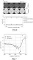
- FIG. 7 represents the real part of the polarizability of a gold nanorod as a function of wavelength measured by quadrilateral shift interferometry.
- a sharp jump is observed around 700 nm, corresponding to the plasmon resonance of the nanoparticle.
- Such a sharp jump makes it possible to obtain a sensitive detection probe, by measuring the variation over time of this optical property of the nanoparticle in the presence of target molecules in the sample.
- the nanoparticles 11 are functionalized with proteins of interest, i.e., antibodies 13 in this case, having a certain affinity for target molecules 12, and connected to the nanoparticles 11 by spacers (or linkers) 14.
- a microfluidic circuit 15 allows the supply of the target molecules 12 to be detected in the sample 10. In this example, this supply is carried out by circulating a solution comprising the target molecules 12 in the microfluidic circuit 15.
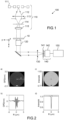
- Such a sample 10 may for example be implemented in an example of a detection device 100 as described in the Figure 1 , configured to determine, over time, at least one optical property of at least one particle.
- the computing unit 150 is further configured for characterizing the interaction with said at least one target molecule 12 on the basis of a measurement of the variation over time of said at least one optical property.
- characterizing the interaction with a target molecule includes detecting interactions between a particle and a target molecule, or between a molecule or ligand attached to a particle. Detection involves providing a qualitative answer to the question of whether particles and target molecules have an affinity, or respectively, whether molecules A (for analyte or target molecule) and molecules L (for ligand) have an affinity.
- molecules A and L are, for example, respectively referenced 12 and 13 in the Figure 8 .
- a solution not containing target molecules 12 is injected into a microfluidic channel 15 connected to a substrate 16 on which particles 11 are attached.
- the particles 11 are functionalized by ligand L molecules, referenced 13, via a spacer 14 connecting the ligand 13 to the particle 11.
- An observable m is measured corresponding to one of the optical properties that is characterized for one or more particles 11 in the presence of this solution, at a well-determined time t 0 after the start of the injection of the solution.
- the said optical property(ies) includes for example the real part, the imaginary part, the argument or the norm of the complex polarizability of the particle(s).
- a second step the same liquid is injected except that this time it contains the target molecules A, referenced 12.
- the new values of observables m of the same particles 11 are measured, at the same determined time t 0 .
- a variation in the value of observable m can be due to the attachment of target molecules 12 to particles 11, but also to the simple presence of target molecules 12 in solution which changes the index, when, for example, the concentration of target molecules 12 is high.
- This second contribution does not does not translate into an attachment between target molecules 12 and ligands 13.
- This effect of the medium or " bulk effect", corresponding to the noise level, can be quantified by repeating the measurements corresponding to the two steps (with and without target molecule 12), in the absence of ligand 13 on particles 11.
- the measurement sequence described above can be applied with N solutions of analytes A or target molecules of known concentrations [ A ] n , n ⁇ [1, N ], successively. We thus obtain N values of observables m n .
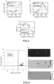
- the data collected ([ A ] n , m n ) constitute a calibration curve, represented in Figure 9b .
- a solution containing target molecules and an unknown concentration of target molecules is then injected into the sample.
- the m value is measured and plotted on the calibration curve to determine the concentration of target molecules.
- the affinity constant K A can be determined by measuring the observable m eq, i for a series of analyte concentrations [A] i at steady state, i.e. waiting long enough for the observable to no longer vary over time.
- the plot of m eq, i versus [A] i can then look like the curve shown in Figure 10 .
- association constants k a and dissociation k d are defined by the chemical reaction (1):
- the coefficients p i of such exponentials correspond to the slopes of the lines obtained by plotting the derivative of the observable m with respect to time as a function of m, for a series of analyte or target molecule concentrations, as illustrated in Figure 11b .
Landscapes
- Chemical & Material Sciences (AREA)
- Physics & Mathematics (AREA)
- Analytical Chemistry (AREA)
- General Physics & Mathematics (AREA)
- Dispersion Chemistry (AREA)
- Health & Medical Sciences (AREA)
- Life Sciences & Earth Sciences (AREA)
- Biochemistry (AREA)
- General Health & Medical Sciences (AREA)
- Immunology (AREA)
- Pathology (AREA)
- Multimedia (AREA)
- Optics & Photonics (AREA)
- Engineering & Computer Science (AREA)
- Computer Vision & Pattern Recognition (AREA)
- Investigating Or Analysing Materials By Optical Means (AREA)
Claims (18)
- Verfahren zur optischen Charakterisierung mindestens eines Teilchens (11), das in einer Probe (10) vorhanden ist, umfassend:- das Beleuchten der Probe (10) mittels eines Lichtstrahls, wobei die Probe (10) in dem Objektraum eines optischen Systems (120) positioniert ist;- das Erfassen mindestens eines Phasenbilds und mindestens eines Intensitätsbilds des mindestens einen von dem Lichtstrahl beleuchteten Teilchens (11), wobei das Erfassen in einer Analyseebene erfolgt, die in dem Bildraum des optischen Systems (120) angeordnet ist;- das Berechnen, ausgehend von dem mindestens einen Phasenbild und von dem mindestens einen Intensitätsbild, eines kombinierten Bilds, wobei das kombinierte Bild ausgehend von der normalisierten komplexen Transmission des Realteils der normalisierten komplexen Transmission oder des Imaginärteils der normalisierten komplexen Transmission erhalten wird; wobei das Verfahren dadurch gekennzeichnet ist, dass es ferner umfasst:- das Summieren von Punkten des kombinierten Bilds auf einem gegebenen Bereich des kombinierten Bilds, das ein Bild des mindestens einen Teilchens umfasst;- das Bestimmen mindestens einer optischen Eigenschaft des mindestens einen Teilchens (11) ausgehend von der Summe, wobei die mindestens eine optische Eigenschaft mindestens eine(n) unter der komplexen Dipol-Polarisierbarkeit, dem Absorptionsquerschnitt, dem Streuquerschnitt, dem Extinktionsquerschnitt umfasst.
- Verfahren nach Anspruch 1, wobei das mindestens eine Intensitätsbild und das mindestens eine Phasenbild gleichzeitig erfasst werden.
- Verfahren nach einem der vorhergehenden Ansprüche, umfassend ferner:- das Ändern der numerischen Apertur des optischen Systems, was es ermöglicht, eine Vielzahl von numerischen Aperturen zu erzeugen; und- das Erfassen einer Vielzahl von Intensitätsbildern und Phasenbildern mit den numerischen Aperturen.
- Verfahren nach einem der vorhergehenden Ansprüche, umfassend ferner:- das Ändern des Abstands zwischen der Probe und dem optischen System, was es ermöglicht, eine Vielzahl von Abständen zu erzeugen; und- das Erfassen einer Vielzahl von Intensitätsbildern und Phasenbildern für die Vielzahl von Abständen.
- Verfahren zur Charakterisierung der Wechselwirkung mindestens eines Zielmoleküls (12) mit dem mindestens einen Teilchen (11), umfassend:- eine optische Charakterisierung des mindestens einen Teilchens (11) nach einem der vorhergehenden Ansprüche, um im Laufe der Zeit mindestens eine der optischen Eigenschaften zu bestimmen;- die Charakterisierung der Interaktion mit dem mindestens einen Zielmolekül (12) auf der Grundlage einer Messung der Änderung der mindestens einen optischen Eigenschaft im Laufe der Zeit.
- Verfahren nach Anspruch 5, wobei die mindestens eine optische Eigenschaft mindestens eine(n) unter dem Realteil, dem Argument, der Norm oder dem Imaginärteil der komplexen Polarisierbarkeit des mindestens einen Teilchens (11) umfasst.
- Verfahren nach einem der Ansprüche 5 oder 6, wobei das mindestens eine Teilchen (11) ein Metallteilchen ist und die Beleuchtung der Probe (10) eine Illumination in einem Wellenlängenbereich umfasst, der eine Plasmonenresonanzwellenlänge des mindestens einen Teilchens (11) umfasst.
- Verfahren nach einem der Ansprüche 5 bis 7, wobei die Beleuchtung der Probe (10) eine Illumination in einem Wellenlängenbereich umfasst, der eine Mie-Resonanzwellenlänge des mindestens einen Teilchens (11) umfasst.
- Verfahren nach einem der Ansprüche 5 bis 8, umfassend ferner einen vorherigen Schritt zur Kalibrierung der optischen Eigenschaft in Abhängigkeit von der Konzentration des mindestens einen Zielmoleküls (12), wobei die Kalibrierung durchgeführt wird, indem die optische Eigenschaft zu einer vorbestimmten Zeit für eine Reihen von Proben mit bekannten Konzentrationen des Zielmoleküls (12) gemessen wird, und
wobei die Charakterisierung der Wechselwirkung mit dem mindestens einen Zielmolekül (12) eine Bestimmung der Konzentration des Zielmoleküls (12) in der Probe (10) umfasst, die auf der Kalibrierung beruht. - Verfahren nach einem der Ansprüche 5 bis 9, umfassend ferner:- das Bilden einer Vielzahl von Proben, die das mindestens eine Teilchen und das mindestens eine Zielmolekül umfassen, mit einer Vielzahl von bekannten Konzentrationen;- die optische Charakterisierung des mindestens einen Teilchens für jede Probe der Vielzahl von Proben; und wobei:- die Charakterisierung der Wechselwirkung mit dem mindestens einen Zielmolekül (12) eine Bestimmung der Affinitäts- und/oder Assoziations- und/oder Dissoziationskonstante eines Zielmoleküls (12) mit dem mindestens einen Teilchen (11) oder mit einem zuvor an das mindestens eine Teilchen (11) angehefteten Molekül (13) umfasst, wobei die Affinitäts- und/oder Assoziations- und/oder Dissoziationskonstante auf der Grundlage der Änderung der optischen Eigenschaft im Laufe der Zeit für die Vielzahl von Proben bestimmt wird.
- Vorrichtung (100) zur optischen Charakterisierung mindestens eines Teilchens (11), das in einer Probe (10) vorhanden ist, umfassend:- eine Lichtquelle (110) zum Bilden eines Strahls zur Beleuchtung der Probe (10);- ein optisches System (120), wobei die Probe (10), während des Vorgangs, in dem Objektraum des optischen Systems (120) positioniert ist;- eine Erfassungseinheit (130, 140) zum Erfassen mindestens eines Phasenbilds und mindestens eines Intensitätsbilds des mindestens einen von dem Lichtstrahl beleuchteten Teilchens (11), wobei das Erfassen in einer Analyseebene erfolgt, die in dem Bildraum des optischen Systems (120) angeordnet ist; und- eine Verarbeitungseinheit (150), die ausgestaltet ist zum:- Berechnen, ausgehend von dem mindestens einen Phasenbild und von dem mindestens einen Intensitätsbild, eines kombinierten Bilds, wobei das kombinierte Bild ausgehend von der normalisierten komplexen Transmission des Realteils der normalisierten komplexen Transmission oder des Imaginärteils der normalisierten komplexen Transmission erhalten wird; dadurch gekennzeichnet, dass die Recheneinheit (150) ferner ausgestaltet ist zum:- Summieren von Punkten des kombinierten Bilds auf einem gegebenen Bereich des kombinierten Bilds, das ein Bild des mindestens einen Teilchens umfasst;- Bestimmen mindestens einer optischen Eigenschaft des mindestens einen Teilchens (11) ausgehend von der Summe, wobei die mindestens eine optische Eigenschaft mindestens eine(n) unter der komplexen Dipol-Polarisierbarkeit, dem Absorptionsquerschnitt, dem Streuquerschnitt, dem Extinktionsquerschnitt umfasst.
- Vorrichtung nach Anspruch 11, wobei die Erfassungseinheit (130, 140) ein Lateral-Shearing-Interferometer (140) umfasst.
- Vorrichtung nach einem der Ansprüche 11 oder 12, wobei das optische System (120) ein Mikroskop-Objektiv umfasst.
- Vorrichtung nach einem der Ansprüche 11 bis 13, wobei das optische System (120) eine variable numerische Apertur umfasst und die Recheneinheit (150) zur Bestimmung der mindestens einen optischen Eigenschaft ausgehend von einer Vielzahl von Phasenbildern und Intensitätsbildern, die für eine Vielzahl von numerischen Aperturen erfasst werden, ausgestaltet ist.
- Vorrichtung nach einem der Ansprüche 11 bis 14, wobei die Recheneinheit (150) zur Bestimmung der mindestens einen optischen Eigenschaft ausgehend von einer Vielzahl von Phasenbildern und Intensitätsbildern, die für eine Vielzahl von Abständen zwischen der Probe und dem optischen System erfasst werden, ausgestaltet ist.
- Vorrichtung zur Charakterisierung der Wechselwirkung mindestens eines Zielmoleküls (12) mit mindestens einem Teilchen (11), das in einer Probe (10) vorhanden ist, umfassend:- eine Vorrichtung (100) zur optischen Charakterisierung des mindestens einen Teilchens (11) nach einem der Ansprüche 11 bis 15, die dazu ausgestaltet ist, im Laufe der Zeit mindestens eine optische Eigenschaft des mindestens einen Teilchens zu bestimmen; und wobei:- die Recheneinheit (150) ferner zur Charakterisierung der Wechselwirkung mit dem mindestens einen Zielmolekül (12) auf der Grundlage einer Messung der Änderung der mindestens einen optischen Eigenschaft im Laufe der Zeit ausgestaltet ist.
- Vorrichtung (100) nach Anspruch 16, wobei die mindestens eine optische Eigenschaft mindestens eine(n) unter dem Realteil, dem Argument, der Norm oder dem Imaginärteil der komplexen Polarisierbarkeit des mindestens einen Teilchens (11) umfasst.
- Vorrichtung (100) nach einem der Ansprüche 16 oder 17, umfassend ferner einen mikrofluidischen Kreis (15), um das mindestens eine Zielmolekül (12) in die Probe (10) zu bringen.
Applications Claiming Priority (4)
| Application Number | Priority Date | Filing Date | Title |
|---|---|---|---|
| FR1909601A FR3100332A1 (fr) | 2019-08-30 | 2019-08-30 | Méthode et dispositif de caractérisation optique de particules |
| FR1909592A FR3100339A1 (fr) | 2019-08-30 | 2019-08-30 | Méthode de détection de l’ interaction de molécules cibles avec des particules |
| FR1912525A FR3100335B1 (fr) | 2019-08-30 | 2019-11-07 | Méthode et dispositif de caractérisation optique de particules |
| PCT/EP2020/073892 WO2021037935A1 (fr) | 2019-08-30 | 2020-08-26 | Méthode et dispositif de caractérisation optique de particules |
Publications (2)
| Publication Number | Publication Date |
|---|---|
| EP4022280A1 EP4022280A1 (de) | 2022-07-06 |
| EP4022280B1 true EP4022280B1 (de) | 2025-06-25 |
Family
ID=72470321
Family Applications (1)
| Application Number | Title | Priority Date | Filing Date |
|---|---|---|---|
| EP20771211.8A Active EP4022280B1 (de) | 2019-08-30 | 2020-08-26 | Verfahren und vorrichtung zur optischen charakterisierung von partikeln |
Country Status (3)
| Country | Link |
|---|---|
| US (1) | US12055471B2 (de) |
| EP (1) | EP4022280B1 (de) |
| WO (1) | WO2021037935A1 (de) |
Families Citing this family (2)
| Publication number | Priority date | Publication date | Assignee | Title |
|---|---|---|---|---|
| EP4427021A4 (de) * | 2021-11-01 | 2025-12-24 | Holtra Ab | Verfahren und anordnung zur optischen detektion von dielektrischen partikeln |
| SE2230165A1 (en) * | 2021-11-01 | 2023-05-02 | Holtra Ab | Method and arrangement for optical detection of dielectric particles |
Citations (2)
| Publication number | Priority date | Publication date | Assignee | Title |
|---|---|---|---|---|
| US20030064386A1 (en) * | 2001-09-28 | 2003-04-03 | Olympus Optical Co., Ltd. | Probe array for detecting a target material using stereo-substrate |
| US20090325199A1 (en) * | 2005-08-02 | 2009-12-31 | University Of Maryland Biotechnology Institute | Nanostructures for polarized imaging and receptor/ligan quantization: breaking the diffraction limit for imaging |
Family Cites Families (9)
| Publication number | Priority date | Publication date | Assignee | Title |
|---|---|---|---|---|
| US8184298B2 (en) * | 2008-05-21 | 2012-05-22 | The Board Of Trustees Of The University Of Illinois | Spatial light interference microscopy and fourier transform light scattering for cell and tissue characterization |
| DE102012205311B4 (de) * | 2012-03-30 | 2013-10-17 | Anton Paar Gmbh | Optische Vorrichtung, insbesondere Polarimeter, zur Detektion von Inhomogenitäten in einer Probe |
| JP6112872B2 (ja) * | 2013-01-18 | 2017-04-12 | キヤノン株式会社 | 撮像システム、画像処理方法、および撮像装置 |
| US9377292B2 (en) * | 2013-08-06 | 2016-06-28 | Zygo Corporation | Interferometry employing refractive index dispersion broadening of interference signals |
| FR3013128B1 (fr) * | 2013-11-13 | 2016-01-01 | Univ Aix Marseille | Dispositif et methode de mise au point tridimensionnelle pour microscope |
| US9377400B2 (en) * | 2014-03-31 | 2016-06-28 | Redshift Systems Corporation | Motion modulation fluidic analyzer system |
| DE102014017552A1 (de) * | 2014-10-15 | 2016-04-21 | Retsch Technology Gmbh | Vorrichtung und Verfahren zur Bestimmung der Partikelgröße und/oder der Partikelform von Partikeln in einem Partikelstrom |
| US10393643B2 (en) * | 2016-09-07 | 2019-08-27 | Rochester Institute Of Technology | Optical vortex coronagraph scatterometer |
| GB201711886D0 (en) * | 2017-07-24 | 2017-09-06 | Univ College Cardiff Consultants Ltd | Analysing nano - objects |
-
2020
- 2020-08-26 EP EP20771211.8A patent/EP4022280B1/de active Active
- 2020-08-26 US US17/753,210 patent/US12055471B2/en active Active
- 2020-08-26 WO PCT/EP2020/073892 patent/WO2021037935A1/fr not_active Ceased
Patent Citations (2)
| Publication number | Priority date | Publication date | Assignee | Title |
|---|---|---|---|---|
| US20030064386A1 (en) * | 2001-09-28 | 2003-04-03 | Olympus Optical Co., Ltd. | Probe array for detecting a target material using stereo-substrate |
| US20090325199A1 (en) * | 2005-08-02 | 2009-12-31 | University Of Maryland Biotechnology Institute | Nanostructures for polarized imaging and receptor/ligan quantization: breaking the diffraction limit for imaging |
Also Published As
| Publication number | Publication date |
|---|---|
| WO2021037935A1 (fr) | 2021-03-04 |
| EP4022280A1 (de) | 2022-07-06 |
| US12055471B2 (en) | 2024-08-06 |
| US20220283070A1 (en) | 2022-09-08 |
Similar Documents
| Publication | Publication Date | Title |
|---|---|---|
| Bai et al. | Bond-selective imaging by optically sensing the mid-infrared photothermal effect | |
| EP3274689B1 (de) | Verfahren und vorrichtung zur analyse von partikeln | |
| Gaiduk et al. | Detection limits in photothermal microscopy | |
| Lee et al. | Hyperbolic material enhanced scattering nanoscopy for label-free super-resolution imaging | |
| EP3274694B1 (de) | Verfahren zur bestimmung des zustandes einer zelle | |
| Vermeulen et al. | Photothermal microscopy: optical detection of small absorbers in scattering environments | |
| Liu et al. | Flexible hyperspectral surface plasmon resonance microscopy | |
| Craig et al. | Mid-to long-wave infrared computational spectroscopy using a subwavelength coaxial aperture array | |
| Ortiz-Orruno et al. | Simultaneous sizing and refractive index analysis of heterogeneous nanoparticle suspensions | |
| EP3658894B1 (de) | Analyse von nano-objekten | |
| Daloglu et al. | Computational on-chip imaging of nanoparticles and biomolecules using ultraviolet light | |
| Thadson et al. | Deep learning-based single-shot phase retrieval algorithm for surface plasmon resonance microscope based refractive index sensing application | |
| US12147022B2 (en) | Dark-field mid-infrared photothermal microscopy | |
| Thiele et al. | Single-protein optical holography | |
| EP4022280B1 (de) | Verfahren und vorrichtung zur optischen charakterisierung von partikeln | |
| WO2018050972A1 (fr) | Dispositif optique de caractérisation d'un échantillon | |
| Turko et al. | Wide-field interferometric phase microscopy with molecular specificity using plasmonic nanoparticles | |
| FR3100335A1 (fr) | Méthode et dispositif de caractérisation optique de particules | |
| Šubr et al. | Anisotropic optical response of silver nanorod arrays: surface enhanced raman scattering polarization and angular dependences confronted with ellipsometric parameters | |
| Ilchenko et al. | Wide Line Surface‐Enhanced Raman Scattering Mapping | |
| Holub et al. | Not Just Better Resolution: A Detailed Study of the Signal Distribution in Mid-Infrared Optical Photothermal Imaging | |
| EP3443362B1 (de) | Verfahren und vorrichtung zur positionierung eines mikro- oder nano-objekts unter visueller kontrolle | |
| WO2024003470A1 (fr) | Dispositif d'amplification d'un signal en imagerie de phase quantitative autoreferencee | |
| FR3100332A1 (fr) | Méthode et dispositif de caractérisation optique de particules | |
| Nahmad-Rohen et al. | Simultaneous microscopic imaging of thickness and refractive index of thin layers by heterodyne interferometric reflectometry (HiRef) |
Legal Events
| Date | Code | Title | Description |
|---|---|---|---|
| STAA | Information on the status of an ep patent application or granted ep patent |
Free format text: STATUS: UNKNOWN |
|
| STAA | Information on the status of an ep patent application or granted ep patent |
Free format text: STATUS: THE INTERNATIONAL PUBLICATION HAS BEEN MADE |
|
| PUAI | Public reference made under article 153(3) epc to a published international application that has entered the european phase |
Free format text: ORIGINAL CODE: 0009012 |
|
| STAA | Information on the status of an ep patent application or granted ep patent |
Free format text: STATUS: REQUEST FOR EXAMINATION WAS MADE |
|
| 17P | Request for examination filed |
Effective date: 20220315 |
|
| AK | Designated contracting states |
Kind code of ref document: A1 Designated state(s): AL AT BE BG CH CY CZ DE DK EE ES FI FR GB GR HR HU IE IS IT LI LT LU LV MC MK MT NL NO PL PT RO RS SE SI SK SM TR |
|
| DAV | Request for validation of the european patent (deleted) | ||
| DAX | Request for extension of the european patent (deleted) | ||
| STAA | Information on the status of an ep patent application or granted ep patent |
Free format text: STATUS: EXAMINATION IS IN PROGRESS |
|
| 17Q | First examination report despatched |
Effective date: 20240417 |
|
| GRAP | Despatch of communication of intention to grant a patent |
Free format text: ORIGINAL CODE: EPIDOSNIGR1 |
|
| STAA | Information on the status of an ep patent application or granted ep patent |
Free format text: STATUS: GRANT OF PATENT IS INTENDED |
|
| INTG | Intention to grant announced |
Effective date: 20250122 |
|
| GRAS | Grant fee paid |
Free format text: ORIGINAL CODE: EPIDOSNIGR3 |
|
| GRAA | (expected) grant |
Free format text: ORIGINAL CODE: 0009210 |
|
| STAA | Information on the status of an ep patent application or granted ep patent |
Free format text: STATUS: THE PATENT HAS BEEN GRANTED |
|
| AK | Designated contracting states |
Kind code of ref document: B1 Designated state(s): AL AT BE BG CH CY CZ DE DK EE ES FI FR GB GR HR HU IE IS IT LI LT LU LV MC MK MT NL NO PL PT RO RS SE SI SK SM TR |
|
| REG | Reference to a national code |
Ref country code: GB Ref legal event code: FG4D Free format text: NOT ENGLISH |
|
| REG | Reference to a national code |
Ref country code: CH Ref legal event code: EP |
|
| REG | Reference to a national code |
Ref country code: CH Ref legal event code: EP |
|
| REG | Reference to a national code |
Ref country code: IE Ref legal event code: FG4D Free format text: LANGUAGE OF EP DOCUMENT: FRENCH |
|
| REG | Reference to a national code |
Ref country code: DE Ref legal event code: R096 Ref document number: 602020053367 Country of ref document: DE |
|
| PG25 | Lapsed in a contracting state [announced via postgrant information from national office to epo] |
Ref country code: FI Free format text: LAPSE BECAUSE OF FAILURE TO SUBMIT A TRANSLATION OF THE DESCRIPTION OR TO PAY THE FEE WITHIN THE PRESCRIBED TIME-LIMIT Effective date: 20250625 |
|
| REG | Reference to a national code |
Ref country code: LT Ref legal event code: MG9D |
|
| PG25 | Lapsed in a contracting state [announced via postgrant information from national office to epo] |
Ref country code: NO Free format text: LAPSE BECAUSE OF FAILURE TO SUBMIT A TRANSLATION OF THE DESCRIPTION OR TO PAY THE FEE WITHIN THE PRESCRIBED TIME-LIMIT Effective date: 20250925 |
|
| PG25 | Lapsed in a contracting state [announced via postgrant information from national office to epo] |
Ref country code: BG Free format text: LAPSE BECAUSE OF FAILURE TO SUBMIT A TRANSLATION OF THE DESCRIPTION OR TO PAY THE FEE WITHIN THE PRESCRIBED TIME-LIMIT Effective date: 20250625 |
|
| PG25 | Lapsed in a contracting state [announced via postgrant information from national office to epo] |
Ref country code: HR Free format text: LAPSE BECAUSE OF FAILURE TO SUBMIT A TRANSLATION OF THE DESCRIPTION OR TO PAY THE FEE WITHIN THE PRESCRIBED TIME-LIMIT Effective date: 20250625 |
|
| PG25 | Lapsed in a contracting state [announced via postgrant information from national office to epo] |
Ref country code: RS Free format text: LAPSE BECAUSE OF FAILURE TO SUBMIT A TRANSLATION OF THE DESCRIPTION OR TO PAY THE FEE WITHIN THE PRESCRIBED TIME-LIMIT Effective date: 20250925 |
|
| PG25 | Lapsed in a contracting state [announced via postgrant information from national office to epo] |
Ref country code: LV Free format text: LAPSE BECAUSE OF FAILURE TO SUBMIT A TRANSLATION OF THE DESCRIPTION OR TO PAY THE FEE WITHIN THE PRESCRIBED TIME-LIMIT Effective date: 20250625 |
|
| REG | Reference to a national code |
Ref country code: NL Ref legal event code: MP Effective date: 20250625 |
|
| PG25 | Lapsed in a contracting state [announced via postgrant information from national office to epo] |
Ref country code: NL Free format text: LAPSE BECAUSE OF FAILURE TO SUBMIT A TRANSLATION OF THE DESCRIPTION OR TO PAY THE FEE WITHIN THE PRESCRIBED TIME-LIMIT Effective date: 20250625 |
|
| PG25 | Lapsed in a contracting state [announced via postgrant information from national office to epo] |
Ref country code: PT Free format text: LAPSE BECAUSE OF FAILURE TO SUBMIT A TRANSLATION OF THE DESCRIPTION OR TO PAY THE FEE WITHIN THE PRESCRIBED TIME-LIMIT Effective date: 20251027 |
|
| REG | Reference to a national code |
Ref country code: AT Ref legal event code: MK05 Ref document number: 1806901 Country of ref document: AT Kind code of ref document: T Effective date: 20250625 |
|
| PG25 | Lapsed in a contracting state [announced via postgrant information from national office to epo] |
Ref country code: IS Free format text: LAPSE BECAUSE OF FAILURE TO SUBMIT A TRANSLATION OF THE DESCRIPTION OR TO PAY THE FEE WITHIN THE PRESCRIBED TIME-LIMIT Effective date: 20251025 |
|
| PG25 | Lapsed in a contracting state [announced via postgrant information from national office to epo] |
Ref country code: AT Free format text: LAPSE BECAUSE OF FAILURE TO SUBMIT A TRANSLATION OF THE DESCRIPTION OR TO PAY THE FEE WITHIN THE PRESCRIBED TIME-LIMIT Effective date: 20250625 Ref country code: SM Free format text: LAPSE BECAUSE OF FAILURE TO SUBMIT A TRANSLATION OF THE DESCRIPTION OR TO PAY THE FEE WITHIN THE PRESCRIBED TIME-LIMIT Effective date: 20250625 |
|
| PG25 | Lapsed in a contracting state [announced via postgrant information from national office to epo] |
Ref country code: CZ Free format text: LAPSE BECAUSE OF FAILURE TO SUBMIT A TRANSLATION OF THE DESCRIPTION OR TO PAY THE FEE WITHIN THE PRESCRIBED TIME-LIMIT Effective date: 20250625 |
|
| PG25 | Lapsed in a contracting state [announced via postgrant information from national office to epo] |
Ref country code: PL Free format text: LAPSE BECAUSE OF FAILURE TO SUBMIT A TRANSLATION OF THE DESCRIPTION OR TO PAY THE FEE WITHIN THE PRESCRIBED TIME-LIMIT Effective date: 20250625 |
|
| PG25 | Lapsed in a contracting state [announced via postgrant information from national office to epo] |
Ref country code: EE Free format text: LAPSE BECAUSE OF FAILURE TO SUBMIT A TRANSLATION OF THE DESCRIPTION OR TO PAY THE FEE WITHIN THE PRESCRIBED TIME-LIMIT Effective date: 20250625 |
|
| PG25 | Lapsed in a contracting state [announced via postgrant information from national office to epo] |
Ref country code: SK Free format text: LAPSE BECAUSE OF FAILURE TO SUBMIT A TRANSLATION OF THE DESCRIPTION OR TO PAY THE FEE WITHIN THE PRESCRIBED TIME-LIMIT Effective date: 20250625 |
|
| PG25 | Lapsed in a contracting state [announced via postgrant information from national office to epo] |
Ref country code: ES Free format text: LAPSE BECAUSE OF FAILURE TO SUBMIT A TRANSLATION OF THE DESCRIPTION OR TO PAY THE FEE WITHIN THE PRESCRIBED TIME-LIMIT Effective date: 20250625 |
|
| REG | Reference to a national code |
Ref country code: DE Ref legal event code: R119 Ref document number: 602020053367 Country of ref document: DE |
|
| PG25 | Lapsed in a contracting state [announced via postgrant information from national office to epo] |
Ref country code: RO Free format text: LAPSE BECAUSE OF FAILURE TO SUBMIT A TRANSLATION OF THE DESCRIPTION OR TO PAY THE FEE WITHIN THE PRESCRIBED TIME-LIMIT Effective date: 20250625 |
|
| REG | Reference to a national code |
Ref country code: CH Ref legal event code: H13 Free format text: ST27 STATUS EVENT CODE: U-0-0-H10-H13 (AS PROVIDED BY THE NATIONAL OFFICE) Effective date: 20260324 |
|
| PG25 | Lapsed in a contracting state [announced via postgrant information from national office to epo] |
Ref country code: MC Free format text: LAPSE BECAUSE OF FAILURE TO SUBMIT A TRANSLATION OF THE DESCRIPTION OR TO PAY THE FEE WITHIN THE PRESCRIBED TIME-LIMIT Effective date: 20250625 |
|
| PG25 | Lapsed in a contracting state [announced via postgrant information from national office to epo] |
Ref country code: DK Free format text: LAPSE BECAUSE OF FAILURE TO SUBMIT A TRANSLATION OF THE DESCRIPTION OR TO PAY THE FEE WITHIN THE PRESCRIBED TIME-LIMIT Effective date: 20250625 |
|
| PG25 | Lapsed in a contracting state [announced via postgrant information from national office to epo] |
Ref country code: LU Free format text: LAPSE BECAUSE OF NON-PAYMENT OF DUE FEES Effective date: 20250826 Ref country code: IT Free format text: LAPSE BECAUSE OF FAILURE TO SUBMIT A TRANSLATION OF THE DESCRIPTION OR TO PAY THE FEE WITHIN THE PRESCRIBED TIME-LIMIT Effective date: 20250625 |
|
| PG25 | Lapsed in a contracting state [announced via postgrant information from national office to epo] |
Ref country code: CH Free format text: LAPSE BECAUSE OF NON-PAYMENT OF DUE FEES Effective date: 20250831 |
|
| PLBE | No opposition filed within time limit |
Free format text: ORIGINAL CODE: 0009261 |
|
| STAA | Information on the status of an ep patent application or granted ep patent |
Free format text: STATUS: NO OPPOSITION FILED WITHIN TIME LIMIT |