EP4021358B1 - Mandibulare vorschubeinrichtung mit automatischer verstellvorrichtung - Google Patents
Mandibulare vorschubeinrichtung mit automatischer verstellvorrichtung Download PDFInfo
- Publication number
- EP4021358B1 EP4021358B1 EP20858076.1A EP20858076A EP4021358B1 EP 4021358 B1 EP4021358 B1 EP 4021358B1 EP 20858076 A EP20858076 A EP 20858076A EP 4021358 B1 EP4021358 B1 EP 4021358B1
- Authority
- EP
- European Patent Office
- Prior art keywords
- wearer
- mandibular advancement
- advancement device
- app
- extraoral
- Prior art date
- Legal status (The legal status is an assumption and is not a legal conclusion. Google has not performed a legal analysis and makes no representation as to the accuracy of the status listed.)
- Active
Links
Images

Classifications
-
- A—HUMAN NECESSITIES
- A61—MEDICAL OR VETERINARY SCIENCE; HYGIENE
- A61F—FILTERS IMPLANTABLE INTO BLOOD VESSELS; PROSTHESES; DEVICES PROVIDING PATENCY TO, OR PREVENTING COLLAPSING OF, TUBULAR STRUCTURES OF THE BODY, e.g. STENTS; ORTHOPAEDIC, NURSING OR CONTRACEPTIVE DEVICES; FOMENTATION; TREATMENT OR PROTECTION OF EYES OR EARS; BANDAGES, DRESSINGS OR ABSORBENT PADS; FIRST-AID KITS
- A61F5/00—Orthopaedic methods or devices for non-surgical treatment of bones or joints; Nursing devices ; Anti-rape devices
- A61F5/56—Devices for preventing snoring
- A61F5/566—Intra-oral devices
-
- A—HUMAN NECESSITIES
- A61—MEDICAL OR VETERINARY SCIENCE; HYGIENE
- A61B—DIAGNOSIS; SURGERY; IDENTIFICATION
- A61B5/00—Measuring for diagnostic purposes; Identification of persons
- A61B5/08—Measuring devices for evaluating the respiratory organs
- A61B5/087—Measuring breath flow
-
- A—HUMAN NECESSITIES
- A61—MEDICAL OR VETERINARY SCIENCE; HYGIENE
- A61B—DIAGNOSIS; SURGERY; IDENTIFICATION
- A61B5/00—Measuring for diagnostic purposes; Identification of persons
- A61B5/08—Measuring devices for evaluating the respiratory organs
- A61B5/097—Devices for facilitating collection of breath or for directing breath into or through measuring devices
-
- A—HUMAN NECESSITIES
- A61—MEDICAL OR VETERINARY SCIENCE; HYGIENE
- A61B—DIAGNOSIS; SURGERY; IDENTIFICATION
- A61B5/00—Measuring for diagnostic purposes; Identification of persons
- A61B5/48—Other medical applications
- A61B5/4836—Diagnosis combined with treatment in closed-loop systems or methods
-
- A—HUMAN NECESSITIES
- A61—MEDICAL OR VETERINARY SCIENCE; HYGIENE
- A61B—DIAGNOSIS; SURGERY; IDENTIFICATION
- A61B5/00—Measuring for diagnostic purposes; Identification of persons
- A61B5/68—Arrangements of detecting, measuring or recording means, e.g. sensors, in relation to patient
- A61B5/6801—Arrangements of detecting, measuring or recording means, e.g. sensors, in relation to patient specially adapted to be attached to or worn on the body surface
- A61B5/6813—Specially adapted to be attached to a specific body part
- A61B5/6814—Head
- A61B5/6819—Nose
-
- A—HUMAN NECESSITIES
- A61—MEDICAL OR VETERINARY SCIENCE; HYGIENE
- A61B—DIAGNOSIS; SURGERY; IDENTIFICATION
- A61B5/00—Measuring for diagnostic purposes; Identification of persons
- A61B5/68—Arrangements of detecting, measuring or recording means, e.g. sensors, in relation to patient
- A61B5/6801—Arrangements of detecting, measuring or recording means, e.g. sensors, in relation to patient specially adapted to be attached to or worn on the body surface
- A61B5/683—Means for maintaining contact with the body
- A61B5/6835—Supports or holders, e.g., articulated arms
-
- G—PHYSICS
- G16—INFORMATION AND COMMUNICATION TECHNOLOGY [ICT] SPECIALLY ADAPTED FOR SPECIFIC APPLICATION FIELDS
- G16H—HEALTHCARE INFORMATICS, i.e. INFORMATION AND COMMUNICATION TECHNOLOGY [ICT] SPECIALLY ADAPTED FOR THE HANDLING OR PROCESSING OF MEDICAL OR HEALTHCARE DATA
- G16H40/00—ICT specially adapted for the management or administration of healthcare resources or facilities; ICT specially adapted for the management or operation of medical equipment or devices
- G16H40/60—ICT specially adapted for the management or administration of healthcare resources or facilities; ICT specially adapted for the management or operation of medical equipment or devices for the operation of medical equipment or devices
- G16H40/63—ICT specially adapted for the management or administration of healthcare resources or facilities; ICT specially adapted for the management or operation of medical equipment or devices for the operation of medical equipment or devices for local operation
-
- A—HUMAN NECESSITIES
- A61—MEDICAL OR VETERINARY SCIENCE; HYGIENE
- A61B—DIAGNOSIS; SURGERY; IDENTIFICATION
- A61B2560/00—Constructional details of operational features of apparatus; Accessories for medical measuring apparatus
- A61B2560/02—Operational features
- A61B2560/0266—Operational features for monitoring or limiting apparatus function
- A61B2560/0271—Operational features for monitoring or limiting apparatus function using a remote monitoring unit
-
- A—HUMAN NECESSITIES
- A61—MEDICAL OR VETERINARY SCIENCE; HYGIENE
- A61B—DIAGNOSIS; SURGERY; IDENTIFICATION
- A61B2560/00—Constructional details of operational features of apparatus; Accessories for medical measuring apparatus
- A61B2560/02—Operational features
- A61B2560/0266—Operational features for monitoring or limiting apparatus function
- A61B2560/0276—Determining malfunction
-
- A—HUMAN NECESSITIES
- A61—MEDICAL OR VETERINARY SCIENCE; HYGIENE
- A61B—DIAGNOSIS; SURGERY; IDENTIFICATION
- A61B5/00—Measuring for diagnostic purposes; Identification of persons
- A61B5/48—Other medical applications
- A61B5/4806—Sleep evaluation
- A61B5/4818—Sleep apnoea
Definitions
- This invention relates to mandibular advancement devices, particularly to devices worn by a person to prevent obstructive sleep apnoea, and in particular to motorised adjustment means that are either operated manually or autonomously, for the extraoral portion of that device.
- a mandibular advancement device of the type referred to in this specification is already disclosed in WO 2019/071291 A1 , which discloses the preamble of claim 1, and WO 2006/072147 .
- the mandibular advancement device disclosed has both intraoral and extraoral portions.
- the present invention is mainly concerned with the extraoral portion of the device.
- the purpose of the device is to adjust the position of the mandible of the wearer so that their airway is clear to enable normal breathing.
- this type of device is worn at night while the wearer is sleeping.
- the device typically includes manual mechanical adjustment means that allow the wearer, or a care giver, to manually adjust the position of the mandible of the wearer.
- the problem with this is that once the position is selected, and the wearer goes to sleep, then the device keeps the mandible in that position during the entire sleep period.
- what may have been the best position for the mandible at the commencement of sleep may not be the best position at other times during the sleep cycle. For example, if the breathing alters during the night, this indicates that the device may need adjusting. Often a partner, care giver, or the wearer themselves needs to intervene and make manual adjustments to the device. This is disruptive and non-conducive to a good night's sleep.
- CN 109 602 534 discloses a lower-jaw advancement snore guard with automatic adjustment.
- a snore guard body is composed of an upper jaw portion, a lower jaw portion and a lower-jaw advancement adjusting device, wherein the upper jaw portion and the lower jaw portion are provided with a customized upper alveolus and a customized lower alveolus, respectively; the lower-jaw advancement adjusting device is provided with a micro speed-reduction motor, a battery, a PLC, a snore sensor, a body position sensor, a nose mouth respiratory air flow sensor, a blood oxygen saturation sensor and a wireless communication device.
- the present invention is a mandibular advancement device according to claim 1.
- the pad assembly includes sensor means that are adapted to sense the airflow emanating from the nose of the wearer as they breath while wearing the device and feed the sensor data collected in real time to logic control means contained within the body portion.
- the logic control means are adapted to process the sensor data it receives to determine if the position of the mandibular of the wearer needs adjusting to improve airflow from the wearer, and if so, then the logic control means are adapted to activate the motorised means to either extend or retract the lower arm for the appropriate distance, thereby causing the pad assembly to apply more or less pressure to the subnasal maxillary bone, and thereby change the position of the mandible of the wearer into the desired position.
- the device further includes manual means that are adapted to enable a user to manually control the motorised means so that the user can set a first desired position for the extraoral portion of the device.
- the manual means includes a switch that causes the motorised means to slide the lower arm out of the body portion when the switch is in a first position, and slidably retract the lower arm when the switch is in the opposite position.
- the switch is a rocker switch.
- the switch is located on the extraoral portion of the body portion.
- the switch is located on the pad assembly as a pair of momentary switches, one for retraction and one for extension.
- the manual means also include a portable device such as a handheld computer, such as a smart phone, wherein said smart phone is wirelessly paired with the logic control means, and wherein the smart phone includes an app that includes manual control means that interact with the logic control means and is adapted to manually cause the motorised means to either extend of retract the lower arm.
- a portable device such as a handheld computer, such as a smart phone
- said smart phone is wirelessly paired with the logic control means
- the smart phone includes an app that includes manual control means that interact with the logic control means and is adapted to manually cause the motorised means to either extend of retract the lower arm.
- the portable device includes an app that records an optimal first position of the extraoral portion of the mandibular advancement device so that when subsequent mandibular advancement devices are paired to the portable device and linked to the specific account within the app, the app controls the optimal first position of that device that is best for that account holder.
- the portable device includes an app that links to an account belonging to the specific wearer of the device, and the account is adapted to receive telemetry from the logic control means, either in real-time, or in batch mode, and this telemetry is logged for that specific wearer within their account for subsequent analysis of breathing patterns and movement of the wearer's mandibular over a time period.
- the app includes alarm means that are enabled if/when the telemetry is lost from the mandibular advancement device.
- the app includes alarm means that are enabled if/when a fault within the adjustment means is detected by the logic control means, or if the battery powering the motorised means reaches a pre-set minimum charge.
- the present invention is a method of adjusting the position of the extraoral portion of a mandibular advancement device, including the steps of:
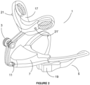
- FIG. 1 where we are shown an isometric view of a mandibular advancement device 1.
- the device includes an extraoral portion 3 and an intraoral portion 5.
- a body portion 7 is at the interface between the two portions and is therefore partly intraoral towards the posterior end and extraoral towards the anterior end.
- Electric motor means (not visible in this view) are encapsulated within the body portion 7.
- the extraoral portion 3 includes a lower straight arm 11 that is adapted to slide into or out of a corresponding opening 13 in the anterior end of the body portion 7.
- the straight arm 11 may include a rack 15 that engages with a pawl on the electric motor to cause the arm to move into or out of the body portion 7 as shown by the double ended arrow.
- a rocker switch 9 is formed in the extraoral portion of the body portion 7 and this is able to control the electric motor means.
- the motorised means act upon the lower arm 11 and forces it to move outwardly, and when the rocker switch 9 is rocked to a second position, the motorised means acts upon lower arm and forces it to move into the body portion .
- the upper portion of the extraoral portion 3 terminates at a pad assembly 17.
- the pad assembly contacts the subnasal maxillary bone of the wearer.
- the upper pad assembly 17 braces against a lower pad 19 that is located on the intraoral portion 5 of the device 1 and contacts the gingiva and/or teeth of the wearer.
- the opposing forces applied by the pad assembly 17 and the lower pad 19 combine to adjust the position of the mandible of the wearer.
- the operator of the rocker switch 9 thereby adjusts the force applied upon the subnasal maxillary bone of the wearer, and thereby causes a change in the position of the wearer's mandible.
- the rocker switch is removed from the body portion 7 and is relocated to the pad assembly 15 as a pair of momentary switches 21 and 21'. These momentary switches act similarly to the rocker switch 9 as shown in Figure 1 .
- momentary switch 21 When an operator, perhaps the wearer, depresses momentary switch 21, the electric motor encapsulated inside the body portion 7 is activated and causes the lower arm 11 to retract into the body portion 7, and when the operator depresses momentary switch 21', the electric motor is activated and causes the lower arm 11 to extend out from the body portion 7.
- the extraoral portion includes electrical wiring, preferably encapsulated within its body that enables the action of either momentary switch to activate the electric motor means within the body portion 7.
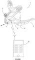
- FIG 3 we are shown another preferred embodiment of the present invention.
- all mechanical switches are removed from the device 1 and the electric motor means are instead controlled wirelessly.
- the body portion 7 includes wireless transmission and receiving means that are adapted to pair with an external computerised device.
- a smart phone 21 is shown.
- the smart phone 21 includes an app that is designed to work with the device 1. In one mode of the app, the operator can use virtual buttons displayed on the smart phone's 21 screen to cause the electric motor means to move the lower arm 11 into or out of the body portion 7.
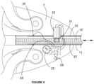
- FIG. 4 we are shown a plan view of the body portion 7 in accordance with one embodiment of the present invention.
- the electric motor 23 mounted inside the lower half of the body portion 7.
- the electric motor 23 is powered by rechargeable battery 25.
- the invention may also include logic control means 27.
- the logic control means may be programmed to provide automatic functionality of the device 1.
- Wireless connectivity may also be included.
- the body portion 7 may also include a wireless antenna 29 that enables the device 1 to wirelessly connect to an external computerised device.
- the electric motor 23 is fitted with a pawl 31 that engages with the rack 15 on the lower arm 11.
- electrical rails 33 and 33' are electrically connected to the slide contacts 35 and 35'
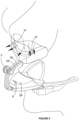
- FIG. 5 we are shown another embodiment of the present invention.
- two airflow sensors 37 and 37' are located directly below the nostrils of the wearer of the device. As the wearer breathes, the sensors 37 and 37' determine the airflow rate. This data is then fed to the logic control means via wires 39 and 39'.
- the logic control means are programmed to analyse the airflow data. If the logic control means determine that the flowrate associated with the wearer's breathing has changed sufficiently, then the logic control means are programmed to autonomously engage the electric motor means and adjust the position of the wearer's mandible in an attempt to affect the wearer's breathing and return the rate of airflow back within a set of control limits.
- the logic control means may also send telemetry wirelessly to an external computerised device.
- This arrangement makes the device 1 completely automatic. Once the nominal breathing rate is determined, and the maximum and minimum control points set, then the device will automatically alter the position of the wearer's mandible in an autonomous attempt to correct undesirable changes in breathing.
- the telemetry sent to the external computerised device is capable of giving the wearer and other carers and health service professionals valuable insights into the wearer's breathing patterns while using the device.
- the device may also include a manual override, as shown in this example as rocker switch 9 so that a wearer can take manual control of the device.
- a slider switch may be included on either the body, or the pad assembly that enables a wearer or care giver to switch off the automatic mode of operation.
Landscapes
- Health & Medical Sciences (AREA)
- Life Sciences & Earth Sciences (AREA)
- Engineering & Computer Science (AREA)
- Biomedical Technology (AREA)
- General Health & Medical Sciences (AREA)
- Public Health (AREA)
- Heart & Thoracic Surgery (AREA)
- Animal Behavior & Ethology (AREA)
- Veterinary Medicine (AREA)
- Medical Informatics (AREA)
- Biophysics (AREA)
- Molecular Biology (AREA)
- Surgery (AREA)
- Physics & Mathematics (AREA)
- Pathology (AREA)
- Pulmonology (AREA)
- Otolaryngology (AREA)
- Nursing (AREA)
- Orthopedic Medicine & Surgery (AREA)
- Vascular Medicine (AREA)
- Physiology (AREA)
- Business, Economics & Management (AREA)
- General Business, Economics & Management (AREA)
- Epidemiology (AREA)
- Primary Health Care (AREA)
- Orthopedics, Nursing, And Contraception (AREA)
Claims (12)
- Unterkieferprotrusionsvorrichtung vom Typ mit sowohl intraoralen (5) als auch extraoralen Abschnitten (3), wobei der extraorale Abschnitt (3) einen unteren Arm (11), der im Wesentlichen gerade ist, und einen gekrümmten oberen Arm, der sich von dem unteren Arm (11) nach oben und zurück in Richtung eines Gesichts eines Trägers der Vorrichtung krümmt, einschließt, wobei das hintere Ende des oberen Arms eine Auflageanordnung (17) einschließt, die angepasst ist, um einen subnasalen Oberkieferknochen des Trägers zu berühren und auf diesen Druck auszuüben,
wobei die Unterkieferprotrusionsvorrichtung ferner Folgendes einschließt:eine Einstelleinrichtung, die einen Körperabschnitt (7) einschließt, der sich an einer Schnittstelle zwischen den intraoralen (5) und extraoralen (3) Abschnitten befindet und dadurch teilweise intraoral und teilweise extraoral ist, wobei die Auflageanordnung (17) der Vorrichtung Sensoreinrichtungen (37, 37') einschließt, die angepasst sind, um den Luftstrom zu erfassen, der beim Atmen von einer Nase des Trägers ausgeht, während dieser die Vorrichtung trägt,dadurch gekennzeichnet, dass:der Körperabschnitt (7) eine innerhalb des Körperabschnitts (7) eingekapselte motorisierte Einrichtung einschließt, wobei ein wesentlicher Abschnitt des unteren Arms (11) mit der motorisierten Einrichtung in Eingriff gebracht werden kann, wobei die motorisierte Einrichtung angepasst ist, um mit dem unteren Arm (11) in Eingriff zu kommen und sie dazu zu veranlassen, gleitend aus dem Körperabschnitt (7) auszufahren oder gleitend in diesen einzufahren, wobei sich der untere Arm (11) direkt nach außen von dem extraoralen Teil des Körperabschnitts erstreckt;wobei die Sensoreinrichtungen (37, 37') auch angepasst sind, um in Echtzeit gesammelte Sensordaten einer Logiksteuerungseinrichtung (27) zuzuführen, die innerhalb des Körperabschnitts (7) enthalten ist; und wobei die Logiksteuerungseinrichtung (27) angepasst ist, um die Sensordaten, die sie empfängt, zu verarbeiten, um zu bestimmen, ob eine Position eines Unterkiefers des Trägers ein Anpassen benötigt, um den Luftstrom vom Träger zu verbessern, und wenn dem so ist, die Logiksteuerungseinrichtung (27) angepasst ist, um die motorisierte Einrichtung zu aktivieren, um den unteren Arm (11) um eine angemessene Strecke entweder auszufahren oder einzufahren, wodurch die Auflageanordnung (17) dazu veranlasst wird, mehr oder weniger Druck auf den subnasalen Oberkieferknochen auszuüben, und wodurch die Position des Unterkiefers des Trägers in eine neue Position verändert wird. - Unterkieferprotrusionsvorrichtung gemäß Definition in Anspruch 1, wobei die Vorrichtung eine manuelle Einrichtung einschließt, die angepasst ist, um eine manuelle Steuerung der motorisierten Einrichtung zu ermöglichen.
- Unterkieferprotrusionsvorrichtung gemäß Definition in Anspruch 2, wobei die manuelle Einrichtung einen Schalter einschließt, der die motorisierte Einrichtung dazu veranlasst, den unteren Arm (11) aus dem Körperabschnitt (7) gleitend auszufahren, wenn der Schalter in einer ersten Position ist, und den unteren Arm (11) in den Körperabschnitt (7) gleitend einzufahren, wenn der Schalter in einer entgegengesetzten Position ist.
- Unterkieferprotrusionsvorrichtung gemäß Definition in Anspruch 3, wobei der Schalter ein Kippschalter ist.
- Unterkieferprotrusionsvorrichtung gemäß Definition in Anspruch 3 oder 4, wobei sich der Schalter am extraoralen Teil des Körperabschnitts (7) befindet.
- Unterkieferprotrusionsvorrichtung gemäß Definition in Anspruch 3 oder 4, wobei sich der Schalter als ein Paar von Momentschaltern, einer für das Einfahren und einer für das Ausfahren, an der Auflageanordnung (17) befindet.
- Unterkieferprotrusionsvorrichtung gemäß Definition in Anspruch 2, wobei die manuelle Einrichtung eine tragbare Vorrichtung einschließt, wobei die tragbare Vorrichtung drahtlos mit der Logiksteuerungseinrichtung (27) gekoppelt ist, wobei die tragbare Vorrichtung eine App einschließt, die eine manuelle Steuerungseinrichtung einschließt, die mit der Logiksteuerungseinrichtung (27) interagiert und angepasst ist, um die motorisierte Einrichtung manuell dazu zu veranlassen, den unteren Arm (11) entweder auszufahren oder einzufahren.
- Unterkieferprotrusionsvorrichtung gemäß Definition in Anspruch 7, wobei die tragbare Vorrichtung eine App einschließt, die angepasst ist, um einem Benutzer der Vorrichtung zu ermöglichen, ein Konto innerhalb der App zu erstellen, wobei die App eine optimale erste Position des extraoralen Abschnitts der Unterkieferprotrusionsvorrichtung aufzeichnet, sodass, wenn nachfolgende Unterkieferprotrusionsvorrichtungen mit der tragbaren Vorrichtung gekoppelt und mit dem Konto innerhalb der App verbunden werden, die App die optimale erste Position einer jeweiligen nachfolgenden Unterkieferprotrusionsvorrichtung steuert.
- Unterkieferprotrusionsvorrichtung gemäß Definition in Anspruch 8, wobei sich die App mit einem Konto verbindet, das dem Träger der Vorrichtung gehört, und das Konto des Trägers angepasst ist, um Telemetrie von der Logiksteuerungseinrichtung (27) entweder in Echtzeit oder im Stapelverarbeitungsmodus zu empfangen, und diese Telemetrie für den Träger innerhalb seines Kontos für eine nachfolgende Analyse von Atmungsmustern und Bewegungen des Unterkiefers des Trägers über einen Zeitraum protokolliert wird.
- Unterkieferprotrusionsvorrichtung gemäß Definition in Anspruch 9, wobei die App Alarmeinrichtungen einschließt, die aktiviert werden, wenn die Telemetrie von der Unterkieferprotrusionsvorrichtung verloren geht.
- Unterkieferprotrusionsvorrichtung gemäß Definition in irgendeinem der Ansprüche 8 bis 10, wobei die App Alarmeinrichtungen einschließt, die aktiviert werden, falls/wenn ein Fehler in der Einstelleinrichtung durch die Logiksteuerungseinrichtung detektiert wird oder falls eine Batterie, die die motorisierte Einrichtung versorgt, eine voreingestellte Mindestladung erreicht.
- Verfahren zum Einstellen einer Position eines extraoralen Abschnitts einer Unterkieferprotrusionsvorrichtung, wobei das Verfahren Folgendes einschließt:a) Koppeln einer Unterkieferprotrusionsvorrichtung mit einem Konto innerhalb einer App auf einer tragbaren Vorrichtung;b) Warten, bis sich der extraorale Abschnitt unter der Kontrolle der App in eine erste Position bewegt;c) Einsetzen eines intraoralen Abschnitts der Unterkieferprotrusionsvorrichtung innerhalb einer Mundhöhle eines Trägers;d) Sicherstellen, dass die Unterkieferprotrusionsvorrichtung ordnungsgemäß angelegt ist, sodass eine Auflageanordnung der Unterkieferprotrusionsvorrichtung einen subnasalen Oberkieferknochen des Trägers ordnungsgemäß berührt;e) Verwenden einer manuellen Einstelleinrichtung der Unterkieferprotrusionsvorrichtung, um die Unterkieferprotrusionsvorrichtung so fein zu justieren, dass der Unterkiefer des Trägers in seiner ursprünglichen optimalen Position ist, sowohl für den Komfort als auch zum Bereitstellen von Luftstromsensoren an der Auflageanordnung, um einen optimalen Luftstrom für den Träger zu einem Beginn seiner Verwendung der Vorrichtung zu erfassen;f) Zuführen von Luftstromsensordaten von den Luftstromsensoren in Echtzeit zu einer Logiksteuerungseinrichtung einer Einstelleinrichtung;g) Ermöglichen, dass die Logiksteuerungseinrichtung die Sensordaten analysiert, um zu bestimmen, ob eine Position des Unterkiefers des Trägers bewegt werden sollte, und wenn bestimmt wird, dass der Unterkiefer bewegt werden sollte; dannh) Erlauben, dass die Logiksteuerungseinrichtung eine motorisierte Einrichtung der Einstelleinrichtung betreibt, um einen unteren Arm des extraoralen Abschnitts entweder auszufahren oder einzufahren, um dadurch die Auflageanordnung dazu zu veranlassen, entweder mehr oder weniger Kraft auf den subnasalen Oberkieferknochen des Trägers auszuüben, wodurch der Unterkiefer des Trägers dazu veranlasst wird, sich zu einer neuen Position zu bewegen.
Applications Claiming Priority (2)
| Application Number | Priority Date | Filing Date | Title |
|---|---|---|---|
| AU2019903108A AU2019903108A0 (en) | 2019-08-26 | Device with Automatic Adjustment Means | |
| PCT/AU2020/000089 WO2021035279A1 (en) | 2019-08-26 | 2020-08-26 | Mandibular advancement device with automatic adjustment means |
Publications (4)
| Publication Number | Publication Date |
|---|---|
| EP4021358A1 EP4021358A1 (de) | 2022-07-06 |
| EP4021358A4 EP4021358A4 (de) | 2023-08-23 |
| EP4021358B1 true EP4021358B1 (de) | 2024-12-18 |
| EP4021358C0 EP4021358C0 (de) | 2024-12-18 |
Family
ID=74683305
Family Applications (1)
| Application Number | Title | Priority Date | Filing Date |
|---|---|---|---|
| EP20858076.1A Active EP4021358B1 (de) | 2019-08-26 | 2020-08-26 | Mandibulare vorschubeinrichtung mit automatischer verstellvorrichtung |
Country Status (4)
| Country | Link |
|---|---|
| US (1) | US12383420B2 (de) |
| EP (1) | EP4021358B1 (de) |
| AU (1) | AU2020339848B2 (de) |
| WO (1) | WO2021035279A1 (de) |
Families Citing this family (1)
| Publication number | Priority date | Publication date | Assignee | Title |
|---|---|---|---|---|
| KR102749316B1 (ko) * | 2022-10-20 | 2025-01-03 | 주식회사 엠디스테이지 | 수면호흡장애 완화장치 및 수면호흡장애 완화시스템 |
Family Cites Families (11)
| Publication number | Priority date | Publication date | Assignee | Title |
|---|---|---|---|---|
| US5678567A (en) | 1994-03-25 | 1997-10-21 | Thornton; W. Keith | Apparatus for adjusting a dental device |
| US5921241A (en) | 1996-03-01 | 1999-07-13 | Belfer; William A. | Anti-snoring device having an adjustable external oral shield |
| US6877513B2 (en) * | 2000-01-21 | 2005-04-12 | Respironics, Inc. | Intraoral apparatus for enhancing airway patency |
| BRPI0606723B8 (pt) * | 2005-01-10 | 2021-06-22 | Yan Guoping | dispositivo ortótico dental |
| CA2876684C (en) * | 2012-06-13 | 2020-08-25 | Zst Holdings, Inc. | Methods and apparatuses for performing remote titration of mandibular protrusion |
| WO2015187949A1 (en) | 2014-06-04 | 2015-12-10 | Giridharagopalan Subhalakshmi | System and method for sensor driven intelligent oral appliance |
| US10537463B2 (en) * | 2015-01-13 | 2020-01-21 | Align Technology, Inc. | Systems and methods for positioning a patient's mandible in response to sleep apnea status |
| US20160354231A1 (en) | 2015-06-08 | 2016-12-08 | Airway Technologies, Llc | Device and system for improved breathing |
| KR101784416B1 (ko) * | 2016-12-15 | 2017-11-06 | 연세대학교 산학협력단 | 코골이 및 수면 무호흡 치료장치 |
| AU2018346995B2 (en) * | 2017-10-13 | 2024-07-11 | BioAnalytics Holdings Pty Ltd | Improvements relating to sleep monitoring |
| CN109602534A (zh) | 2019-01-15 | 2019-04-12 | 兴康明科技(深圳)有限公司 | 一种带有智能化自动调节的下颌前移阻鼾器 |
-
2020
- 2020-08-26 US US17/638,691 patent/US12383420B2/en active Active
- 2020-08-26 WO PCT/AU2020/000089 patent/WO2021035279A1/en not_active Ceased
- 2020-08-26 AU AU2020339848A patent/AU2020339848B2/en active Active
- 2020-08-26 EP EP20858076.1A patent/EP4021358B1/de active Active
Also Published As
| Publication number | Publication date |
|---|---|
| WO2021035279A1 (en) | 2021-03-04 |
| EP4021358C0 (de) | 2024-12-18 |
| AU2020339848B2 (en) | 2025-11-27 |
| EP4021358A1 (de) | 2022-07-06 |
| US12383420B2 (en) | 2025-08-12 |
| EP4021358A4 (de) | 2023-08-23 |
| AU2020339848A1 (en) | 2022-03-10 |
| US20230023562A1 (en) | 2023-01-26 |
Similar Documents
| Publication | Publication Date | Title |
|---|---|---|
| JP7437316B2 (ja) | 離隔した電気部品のセットを有する下顎前方固定装置 | |
| KR101784416B1 (ko) | 코골이 및 수면 무호흡 치료장치 | |
| US12376987B2 (en) | Dynamic mandibular and lingual repositioning devices, controller station, and methods of treating and/or diagnosing medical disorders | |
| CN113571151A (zh) | 用于监控口面肌训练的装置及方法 | |
| KR101929187B1 (ko) | 턱관절 운동기 | |
| CN109789031B (zh) | 用于睡眠呼吸暂停、打鼾和舌及口腔重塑的牙科器具 | |
| EP4021358B1 (de) | Mandibulare vorschubeinrichtung mit automatischer verstellvorrichtung | |
| JP7053651B2 (ja) | 下顎前方固定デバイス、及び、下顎前方固定デバイスの連結アセンブリの寸法を調整する方法 | |
| CN109602534A (zh) | 一种带有智能化自动调节的下颌前移阻鼾器 | |
| KR102222694B1 (ko) | 구강 착용 시스템 및 연구개 및 혀의 위치를 조정하는 방법 | |
| KR20200060715A (ko) | 치과교정용 탄성재의 착용 지속시간을 모니터링 하기 위한 센서 및 시스템 | |
| CN104434356A (zh) | 一种智能牙套 | |
| US20180199857A1 (en) | Antisnoring device | |
| CN209827186U (zh) | 一种带有智能化自动调节的下颌前移阻鼾器 | |
| KR101911279B1 (ko) | 코골이 및 수면 무호흡 치료장치 | |
| KR101640154B1 (ko) | 연하곤란 환자의 흡인 방지 장치 | |
| CN102949771B (zh) | 一种无创伤同步呼吸气道打开器 | |
| US20240066291A1 (en) | Orthodontic devices and systems and methods for using such devices | |
| CN219461453U (zh) | 一种口腔矫治器 | |
| US20220330888A1 (en) | Accessories for a mandible advancement device | |
| EP4193958A1 (de) | Zahnärztlicher kieferorthopädischer beschleuniger | |
| CN211934490U (zh) | 舌背弹性牵拉调节滴定装置 | |
| CN215900620U (zh) | 一种可穿戴的智能开放气道与供氧装置 | |
| US20260000534A1 (en) | Configurable breathing assist mouthpiece device | |
| CN120616815A (zh) | 一种基于电磁铁原理的隐形矫治器 |
Legal Events
| Date | Code | Title | Description |
|---|---|---|---|
| STAA | Information on the status of an ep patent application or granted ep patent |
Free format text: STATUS: THE INTERNATIONAL PUBLICATION HAS BEEN MADE |
|
| PUAI | Public reference made under article 153(3) epc to a published international application that has entered the european phase |
Free format text: ORIGINAL CODE: 0009012 |
|
| STAA | Information on the status of an ep patent application or granted ep patent |
Free format text: STATUS: REQUEST FOR EXAMINATION WAS MADE |
|
| 17P | Request for examination filed |
Effective date: 20220325 |
|
| AK | Designated contracting states |
Kind code of ref document: A1 Designated state(s): AL AT BE BG CH CY CZ DE DK EE ES FI FR GB GR HR HU IE IS IT LI LT LU LV MC MK MT NL NO PL PT RO RS SE SI SK SM TR |
|
| DAV | Request for validation of the european patent (deleted) | ||
| DAX | Request for extension of the european patent (deleted) | ||
| A4 | Supplementary search report drawn up and despatched |
Effective date: 20230721 |
|
| RIC1 | Information provided on ipc code assigned before grant |
Ipc: A61F 5/56 20060101AFI20230717BHEP |
|
| GRAP | Despatch of communication of intention to grant a patent |
Free format text: ORIGINAL CODE: EPIDOSNIGR1 |
|
| STAA | Information on the status of an ep patent application or granted ep patent |
Free format text: STATUS: GRANT OF PATENT IS INTENDED |
|
| INTG | Intention to grant announced |
Effective date: 20240510 |
|
| GRAJ | Information related to disapproval of communication of intention to grant by the applicant or resumption of examination proceedings by the epo deleted |
Free format text: ORIGINAL CODE: EPIDOSDIGR1 |
|
| STAA | Information on the status of an ep patent application or granted ep patent |
Free format text: STATUS: REQUEST FOR EXAMINATION WAS MADE |
|
| GRAP | Despatch of communication of intention to grant a patent |
Free format text: ORIGINAL CODE: EPIDOSNIGR1 |
|
| STAA | Information on the status of an ep patent application or granted ep patent |
Free format text: STATUS: GRANT OF PATENT IS INTENDED |
|
| INTC | Intention to grant announced (deleted) | ||
| INTG | Intention to grant announced |
Effective date: 20240916 |
|
| GRAS | Grant fee paid |
Free format text: ORIGINAL CODE: EPIDOSNIGR3 |
|
| GRAA | (expected) grant |
Free format text: ORIGINAL CODE: 0009210 |
|
| STAA | Information on the status of an ep patent application or granted ep patent |
Free format text: STATUS: THE PATENT HAS BEEN GRANTED |
|
| AK | Designated contracting states |
Kind code of ref document: B1 Designated state(s): AL AT BE BG CH CY CZ DE DK EE ES FI FR GB GR HR HU IE IS IT LI LT LU LV MC MK MT NL NO PL PT RO RS SE SI SK SM TR |
|
| REG | Reference to a national code |
Ref country code: CH Ref legal event code: EP |
|
| REG | Reference to a national code |
Ref country code: DE Ref legal event code: R096 Ref document number: 602020043486 Country of ref document: DE |
|
| REG | Reference to a national code |
Ref country code: IE Ref legal event code: FG4D |
|
| U01 | Request for unitary effect filed |
Effective date: 20241230 |
|
| U07 | Unitary effect registered |
Designated state(s): AT BE BG DE DK EE FI FR IT LT LU LV MT NL PT RO SE SI Effective date: 20250114 |
|
| PG25 | Lapsed in a contracting state [announced via postgrant information from national office to epo] |
Ref country code: HR Free format text: LAPSE BECAUSE OF FAILURE TO SUBMIT A TRANSLATION OF THE DESCRIPTION OR TO PAY THE FEE WITHIN THE PRESCRIBED TIME-LIMIT Effective date: 20241218 |
|
| PG25 | Lapsed in a contracting state [announced via postgrant information from national office to epo] |
Ref country code: GR Free format text: LAPSE BECAUSE OF FAILURE TO SUBMIT A TRANSLATION OF THE DESCRIPTION OR TO PAY THE FEE WITHIN THE PRESCRIBED TIME-LIMIT Effective date: 20250319 |
|
| PG25 | Lapsed in a contracting state [announced via postgrant information from national office to epo] |
Ref country code: RS Free format text: LAPSE BECAUSE OF FAILURE TO SUBMIT A TRANSLATION OF THE DESCRIPTION OR TO PAY THE FEE WITHIN THE PRESCRIBED TIME-LIMIT Effective date: 20250318 |
|
| U1N | Appointed representative for the unitary patent procedure changed after the registration of the unitary effect |
Representative=s name: METIDA; LT |
|
| PG25 | Lapsed in a contracting state [announced via postgrant information from national office to epo] |
Ref country code: SM Free format text: LAPSE BECAUSE OF FAILURE TO SUBMIT A TRANSLATION OF THE DESCRIPTION OR TO PAY THE FEE WITHIN THE PRESCRIBED TIME-LIMIT Effective date: 20241218 |
|
| PG25 | Lapsed in a contracting state [announced via postgrant information from national office to epo] |
Ref country code: PL Free format text: LAPSE BECAUSE OF FAILURE TO SUBMIT A TRANSLATION OF THE DESCRIPTION OR TO PAY THE FEE WITHIN THE PRESCRIBED TIME-LIMIT Effective date: 20241218 |
|
| PG25 | Lapsed in a contracting state [announced via postgrant information from national office to epo] |
Ref country code: ES Free format text: LAPSE BECAUSE OF FAILURE TO SUBMIT A TRANSLATION OF THE DESCRIPTION OR TO PAY THE FEE WITHIN THE PRESCRIBED TIME-LIMIT Effective date: 20241218 |
|
| PG25 | Lapsed in a contracting state [announced via postgrant information from national office to epo] |
Ref country code: IS Free format text: LAPSE BECAUSE OF FAILURE TO SUBMIT A TRANSLATION OF THE DESCRIPTION OR TO PAY THE FEE WITHIN THE PRESCRIBED TIME-LIMIT Effective date: 20250418 |
|
| PG25 | Lapsed in a contracting state [announced via postgrant information from national office to epo] |
Ref country code: SK Free format text: LAPSE BECAUSE OF FAILURE TO SUBMIT A TRANSLATION OF THE DESCRIPTION OR TO PAY THE FEE WITHIN THE PRESCRIBED TIME-LIMIT Effective date: 20241218 |
|
| PG25 | Lapsed in a contracting state [announced via postgrant information from national office to epo] |
Ref country code: CZ Free format text: LAPSE BECAUSE OF FAILURE TO SUBMIT A TRANSLATION OF THE DESCRIPTION OR TO PAY THE FEE WITHIN THE PRESCRIBED TIME-LIMIT Effective date: 20241218 |
|
| U20 | Renewal fee for the european patent with unitary effect paid |
Year of fee payment: 6 Effective date: 20250822 |
|
| PGFP | Annual fee paid to national office [announced via postgrant information from national office to epo] |
Ref country code: NO Payment date: 20250828 Year of fee payment: 6 |
|
| PGFP | Annual fee paid to national office [announced via postgrant information from national office to epo] |
Ref country code: GB Payment date: 20250822 Year of fee payment: 6 |
|
| PLBE | No opposition filed within time limit |
Free format text: ORIGINAL CODE: 0009261 |
|
| STAA | Information on the status of an ep patent application or granted ep patent |
Free format text: STATUS: NO OPPOSITION FILED WITHIN TIME LIMIT |
|
| REG | Reference to a national code |
Ref country code: CH Ref legal event code: L10 Free format text: ST27 STATUS EVENT CODE: U-0-0-L10-L00 (AS PROVIDED BY THE NATIONAL OFFICE) Effective date: 20251029 |
|
| 26N | No opposition filed |
Effective date: 20250919 |
|
| REG | Reference to a national code |
Ref country code: CH Ref legal event code: H13 Free format text: ST27 STATUS EVENT CODE: U-0-0-H10-H13 (AS PROVIDED BY THE NATIONAL OFFICE) Effective date: 20260324 |