EP4021358B1 - Mandibular advancement device with automatic adjustment means - Google Patents
Mandibular advancement device with automatic adjustment means Download PDFInfo
- Publication number
- EP4021358B1 EP4021358B1 EP20858076.1A EP20858076A EP4021358B1 EP 4021358 B1 EP4021358 B1 EP 4021358B1 EP 20858076 A EP20858076 A EP 20858076A EP 4021358 B1 EP4021358 B1 EP 4021358B1
- Authority
- EP
- European Patent Office
- Prior art keywords
- wearer
- mandibular advancement
- advancement device
- app
- extraoral
- Prior art date
- Legal status (The legal status is an assumption and is not a legal conclusion. Google has not performed a legal analysis and makes no representation as to the accuracy of the status listed.)
- Active
Links
Images

Classifications
-
- A—HUMAN NECESSITIES
- A61—MEDICAL OR VETERINARY SCIENCE; HYGIENE
- A61F—FILTERS IMPLANTABLE INTO BLOOD VESSELS; PROSTHESES; DEVICES PROVIDING PATENCY TO, OR PREVENTING COLLAPSING OF, TUBULAR STRUCTURES OF THE BODY, e.g. STENTS; ORTHOPAEDIC, NURSING OR CONTRACEPTIVE DEVICES; FOMENTATION; TREATMENT OR PROTECTION OF EYES OR EARS; BANDAGES, DRESSINGS OR ABSORBENT PADS; FIRST-AID KITS
- A61F5/00—Orthopaedic methods or devices for non-surgical treatment of bones or joints; Nursing devices ; Anti-rape devices
- A61F5/56—Devices for preventing snoring
-
- A—HUMAN NECESSITIES
- A61—MEDICAL OR VETERINARY SCIENCE; HYGIENE
- A61F—FILTERS IMPLANTABLE INTO BLOOD VESSELS; PROSTHESES; DEVICES PROVIDING PATENCY TO, OR PREVENTING COLLAPSING OF, TUBULAR STRUCTURES OF THE BODY, e.g. STENTS; ORTHOPAEDIC, NURSING OR CONTRACEPTIVE DEVICES; FOMENTATION; TREATMENT OR PROTECTION OF EYES OR EARS; BANDAGES, DRESSINGS OR ABSORBENT PADS; FIRST-AID KITS
- A61F5/00—Orthopaedic methods or devices for non-surgical treatment of bones or joints; Nursing devices ; Anti-rape devices
- A61F5/56—Devices for preventing snoring
- A61F5/566—Intra-oral devices
-
- A—HUMAN NECESSITIES
- A61—MEDICAL OR VETERINARY SCIENCE; HYGIENE
- A61B—DIAGNOSIS; SURGERY; IDENTIFICATION
- A61B5/00—Measuring for diagnostic purposes; Identification of persons
- A61B5/08—Measuring devices for evaluating the respiratory organs
- A61B5/087—Measuring breath flow
-
- A—HUMAN NECESSITIES
- A61—MEDICAL OR VETERINARY SCIENCE; HYGIENE
- A61B—DIAGNOSIS; SURGERY; IDENTIFICATION
- A61B5/00—Measuring for diagnostic purposes; Identification of persons
- A61B5/08—Measuring devices for evaluating the respiratory organs
- A61B5/097—Devices for facilitating collection of breath or for directing breath into or through measuring devices
-
- A—HUMAN NECESSITIES
- A61—MEDICAL OR VETERINARY SCIENCE; HYGIENE
- A61B—DIAGNOSIS; SURGERY; IDENTIFICATION
- A61B5/00—Measuring for diagnostic purposes; Identification of persons
- A61B5/48—Other medical applications
- A61B5/4836—Diagnosis combined with treatment in closed-loop systems or methods
-
- A—HUMAN NECESSITIES
- A61—MEDICAL OR VETERINARY SCIENCE; HYGIENE
- A61B—DIAGNOSIS; SURGERY; IDENTIFICATION
- A61B5/00—Measuring for diagnostic purposes; Identification of persons
- A61B5/68—Arrangements of detecting, measuring or recording means, e.g. sensors, in relation to patient
- A61B5/6801—Arrangements of detecting, measuring or recording means, e.g. sensors, in relation to patient specially adapted to be attached to or worn on the body surface
- A61B5/6813—Specially adapted to be attached to a specific body part
- A61B5/6814—Head
- A61B5/6819—Nose
-
- A—HUMAN NECESSITIES
- A61—MEDICAL OR VETERINARY SCIENCE; HYGIENE
- A61B—DIAGNOSIS; SURGERY; IDENTIFICATION
- A61B5/00—Measuring for diagnostic purposes; Identification of persons
- A61B5/68—Arrangements of detecting, measuring or recording means, e.g. sensors, in relation to patient
- A61B5/6801—Arrangements of detecting, measuring or recording means, e.g. sensors, in relation to patient specially adapted to be attached to or worn on the body surface
- A61B5/683—Means for maintaining contact with the body
- A61B5/6835—Supports or holders, e.g., articulated arms
-
- G—PHYSICS
- G16—INFORMATION AND COMMUNICATION TECHNOLOGY [ICT] SPECIALLY ADAPTED FOR SPECIFIC APPLICATION FIELDS
- G16H—HEALTHCARE INFORMATICS, i.e. INFORMATION AND COMMUNICATION TECHNOLOGY [ICT] SPECIALLY ADAPTED FOR THE HANDLING OR PROCESSING OF MEDICAL OR HEALTHCARE DATA
- G16H40/00—ICT specially adapted for the management or administration of healthcare resources or facilities; ICT specially adapted for the management or operation of medical equipment or devices
- G16H40/60—ICT specially adapted for the management or administration of healthcare resources or facilities; ICT specially adapted for the management or operation of medical equipment or devices for the operation of medical equipment or devices
- G16H40/63—ICT specially adapted for the management or administration of healthcare resources or facilities; ICT specially adapted for the management or operation of medical equipment or devices for the operation of medical equipment or devices for local operation
-
- A—HUMAN NECESSITIES
- A61—MEDICAL OR VETERINARY SCIENCE; HYGIENE
- A61B—DIAGNOSIS; SURGERY; IDENTIFICATION
- A61B2560/00—Constructional details of operational features of apparatus; Accessories for medical measuring apparatus
- A61B2560/02—Operational features
- A61B2560/0266—Operational features for monitoring or limiting apparatus function
- A61B2560/0271—Operational features for monitoring or limiting apparatus function using a remote monitoring unit
-
- A—HUMAN NECESSITIES
- A61—MEDICAL OR VETERINARY SCIENCE; HYGIENE
- A61B—DIAGNOSIS; SURGERY; IDENTIFICATION
- A61B2560/00—Constructional details of operational features of apparatus; Accessories for medical measuring apparatus
- A61B2560/02—Operational features
- A61B2560/0266—Operational features for monitoring or limiting apparatus function
- A61B2560/0276—Determining malfunction
-
- A—HUMAN NECESSITIES
- A61—MEDICAL OR VETERINARY SCIENCE; HYGIENE
- A61B—DIAGNOSIS; SURGERY; IDENTIFICATION
- A61B5/00—Measuring for diagnostic purposes; Identification of persons
- A61B5/48—Other medical applications
- A61B5/4806—Sleep evaluation
- A61B5/4818—Sleep apnoea
Definitions
- This invention relates to mandibular advancement devices, particularly to devices worn by a person to prevent obstructive sleep apnoea, and in particular to motorised adjustment means that are either operated manually or autonomously, for the extraoral portion of that device.
- a mandibular advancement device of the type referred to in this specification is already disclosed in WO 2019/071291 A1 , which discloses the preamble of claim 1, and WO 2006/072147 .
- the mandibular advancement device disclosed has both intraoral and extraoral portions.
- the present invention is mainly concerned with the extraoral portion of the device.
- the purpose of the device is to adjust the position of the mandible of the wearer so that their airway is clear to enable normal breathing.
- this type of device is worn at night while the wearer is sleeping.
- the device typically includes manual mechanical adjustment means that allow the wearer, or a care giver, to manually adjust the position of the mandible of the wearer.
- the problem with this is that once the position is selected, and the wearer goes to sleep, then the device keeps the mandible in that position during the entire sleep period.
- what may have been the best position for the mandible at the commencement of sleep may not be the best position at other times during the sleep cycle. For example, if the breathing alters during the night, this indicates that the device may need adjusting. Often a partner, care giver, or the wearer themselves needs to intervene and make manual adjustments to the device. This is disruptive and non-conducive to a good night's sleep.
- CN 109 602 534 discloses a lower-jaw advancement snore guard with automatic adjustment.
- a snore guard body is composed of an upper jaw portion, a lower jaw portion and a lower-jaw advancement adjusting device, wherein the upper jaw portion and the lower jaw portion are provided with a customized upper alveolus and a customized lower alveolus, respectively; the lower-jaw advancement adjusting device is provided with a micro speed-reduction motor, a battery, a PLC, a snore sensor, a body position sensor, a nose mouth respiratory air flow sensor, a blood oxygen saturation sensor and a wireless communication device.
- the present invention is a mandibular advancement device according to claim 1.
- the pad assembly includes sensor means that are adapted to sense the airflow emanating from the nose of the wearer as they breath while wearing the device and feed the sensor data collected in real time to logic control means contained within the body portion.
- the logic control means are adapted to process the sensor data it receives to determine if the position of the mandibular of the wearer needs adjusting to improve airflow from the wearer, and if so, then the logic control means are adapted to activate the motorised means to either extend or retract the lower arm for the appropriate distance, thereby causing the pad assembly to apply more or less pressure to the subnasal maxillary bone, and thereby change the position of the mandible of the wearer into the desired position.
- the device further includes manual means that are adapted to enable a user to manually control the motorised means so that the user can set a first desired position for the extraoral portion of the device.
- the manual means includes a switch that causes the motorised means to slide the lower arm out of the body portion when the switch is in a first position, and slidably retract the lower arm when the switch is in the opposite position.
- the switch is a rocker switch.
- the switch is located on the extraoral portion of the body portion.
- the switch is located on the pad assembly as a pair of momentary switches, one for retraction and one for extension.
- the manual means also include a portable device such as a handheld computer, such as a smart phone, wherein said smart phone is wirelessly paired with the logic control means, and wherein the smart phone includes an app that includes manual control means that interact with the logic control means and is adapted to manually cause the motorised means to either extend of retract the lower arm.
- a portable device such as a handheld computer, such as a smart phone
- said smart phone is wirelessly paired with the logic control means
- the smart phone includes an app that includes manual control means that interact with the logic control means and is adapted to manually cause the motorised means to either extend of retract the lower arm.
- the portable device includes an app that records an optimal first position of the extraoral portion of the mandibular advancement device so that when subsequent mandibular advancement devices are paired to the portable device and linked to the specific account within the app, the app controls the optimal first position of that device that is best for that account holder.
- the portable device includes an app that links to an account belonging to the specific wearer of the device, and the account is adapted to receive telemetry from the logic control means, either in real-time, or in batch mode, and this telemetry is logged for that specific wearer within their account for subsequent analysis of breathing patterns and movement of the wearer's mandibular over a time period.
- the app includes alarm means that are enabled if/when the telemetry is lost from the mandibular advancement device.
- the app includes alarm means that are enabled if/when a fault within the adjustment means is detected by the logic control means, or if the battery powering the motorised means reaches a pre-set minimum charge.
- the present invention is a method of adjusting the position of the extraoral portion of a mandibular advancement device, including the steps of:
- FIG. 1 where we are shown an isometric view of a mandibular advancement device 1.
- the device includes an extraoral portion 3 and an intraoral portion 5.
- a body portion 7 is at the interface between the two portions and is therefore partly intraoral towards the posterior end and extraoral towards the anterior end.
- Electric motor means (not visible in this view) are encapsulated within the body portion 7.
- the extraoral portion 3 includes a lower straight arm 11 that is adapted to slide into or out of a corresponding opening 13 in the anterior end of the body portion 7.
- the straight arm 11 may include a rack 15 that engages with a pawl on the electric motor to cause the arm to move into or out of the body portion 7 as shown by the double ended arrow.
- a rocker switch 9 is formed in the extraoral portion of the body portion 7 and this is able to control the electric motor means.
- the motorised means act upon the lower arm 11 and forces it to move outwardly, and when the rocker switch 9 is rocked to a second position, the motorised means acts upon lower arm and forces it to move into the body portion .
- the upper portion of the extraoral portion 3 terminates at a pad assembly 17.
- the pad assembly contacts the subnasal maxillary bone of the wearer.
- the upper pad assembly 17 braces against a lower pad 19 that is located on the intraoral portion 5 of the device 1 and contacts the gingiva and/or teeth of the wearer.
- the opposing forces applied by the pad assembly 17 and the lower pad 19 combine to adjust the position of the mandible of the wearer.
- the operator of the rocker switch 9 thereby adjusts the force applied upon the subnasal maxillary bone of the wearer, and thereby causes a change in the position of the wearer's mandible.
- the rocker switch is removed from the body portion 7 and is relocated to the pad assembly 15 as a pair of momentary switches 21 and 21'. These momentary switches act similarly to the rocker switch 9 as shown in Figure 1 .
- momentary switch 21 When an operator, perhaps the wearer, depresses momentary switch 21, the electric motor encapsulated inside the body portion 7 is activated and causes the lower arm 11 to retract into the body portion 7, and when the operator depresses momentary switch 21', the electric motor is activated and causes the lower arm 11 to extend out from the body portion 7.
- the extraoral portion includes electrical wiring, preferably encapsulated within its body that enables the action of either momentary switch to activate the electric motor means within the body portion 7.
- FIG 3 we are shown another preferred embodiment of the present invention.
- all mechanical switches are removed from the device 1 and the electric motor means are instead controlled wirelessly.
- the body portion 7 includes wireless transmission and receiving means that are adapted to pair with an external computerised device.
- a smart phone 21 is shown.
- the smart phone 21 includes an app that is designed to work with the device 1. In one mode of the app, the operator can use virtual buttons displayed on the smart phone's 21 screen to cause the electric motor means to move the lower arm 11 into or out of the body portion 7.
- FIG. 4 we are shown a plan view of the body portion 7 in accordance with one embodiment of the present invention.
- the electric motor 23 mounted inside the lower half of the body portion 7.
- the electric motor 23 is powered by rechargeable battery 25.
- the invention may also include logic control means 27.
- the logic control means may be programmed to provide automatic functionality of the device 1.
- Wireless connectivity may also be included.
- the body portion 7 may also include a wireless antenna 29 that enables the device 1 to wirelessly connect to an external computerised device.
- the electric motor 23 is fitted with a pawl 31 that engages with the rack 15 on the lower arm 11.
- electrical rails 33 and 33' are electrically connected to the slide contacts 35 and 35'
- FIG. 5 we are shown another embodiment of the present invention.
- two airflow sensors 37 and 37' are located directly below the nostrils of the wearer of the device. As the wearer breathes, the sensors 37 and 37' determine the airflow rate. This data is then fed to the logic control means via wires 39 and 39'.
- the logic control means are programmed to analyse the airflow data. If the logic control means determine that the flowrate associated with the wearer's breathing has changed sufficiently, then the logic control means are programmed to autonomously engage the electric motor means and adjust the position of the wearer's mandible in an attempt to affect the wearer's breathing and return the rate of airflow back within a set of control limits.
- the logic control means may also send telemetry wirelessly to an external computerised device.
- This arrangement makes the device 1 completely automatic. Once the nominal breathing rate is determined, and the maximum and minimum control points set, then the device will automatically alter the position of the wearer's mandible in an autonomous attempt to correct undesirable changes in breathing.
- the telemetry sent to the external computerised device is capable of giving the wearer and other carers and health service professionals valuable insights into the wearer's breathing patterns while using the device.
- the device may also include a manual override, as shown in this example as rocker switch 9 so that a wearer can take manual control of the device.
- a slider switch may be included on either the body, or the pad assembly that enables a wearer or care giver to switch off the automatic mode of operation.
Landscapes
- Health & Medical Sciences (AREA)
- Life Sciences & Earth Sciences (AREA)
- Engineering & Computer Science (AREA)
- Biomedical Technology (AREA)
- General Health & Medical Sciences (AREA)
- Public Health (AREA)
- Heart & Thoracic Surgery (AREA)
- Animal Behavior & Ethology (AREA)
- Veterinary Medicine (AREA)
- Medical Informatics (AREA)
- Biophysics (AREA)
- Molecular Biology (AREA)
- Surgery (AREA)
- Physics & Mathematics (AREA)
- Pathology (AREA)
- Pulmonology (AREA)
- Otolaryngology (AREA)
- Nursing (AREA)
- Orthopedic Medicine & Surgery (AREA)
- Vascular Medicine (AREA)
- Physiology (AREA)
- Business, Economics & Management (AREA)
- General Business, Economics & Management (AREA)
- Epidemiology (AREA)
- Primary Health Care (AREA)
- Orthopedics, Nursing, And Contraception (AREA)
Description
- This invention relates to mandibular advancement devices, particularly to devices worn by a person to prevent obstructive sleep apnoea, and in particular to motorised adjustment means that are either operated manually or autonomously, for the extraoral portion of that device.
- A mandibular advancement device of the type referred to in this specification is already disclosed in
WO 2019/071291 A1 , which discloses the preamble ofclaim 1, andWO 2006/072147 . The mandibular advancement device disclosed has both intraoral and extraoral portions. The present invention is mainly concerned with the extraoral portion of the device. - The purpose of the device is to adjust the position of the mandible of the wearer so that their airway is clear to enable normal breathing. Typically, this type of device is worn at night while the wearer is sleeping. The device typically includes manual mechanical adjustment means that allow the wearer, or a care giver, to manually adjust the position of the mandible of the wearer. The problem with this is that once the position is selected, and the wearer goes to sleep, then the device keeps the mandible in that position during the entire sleep period. Unfortunately, what may have been the best position for the mandible at the commencement of sleep may not be the best position at other times during the sleep cycle. For example, if the breathing alters during the night, this indicates that the device may need adjusting. Often a partner, care giver, or the wearer themselves needs to intervene and make manual adjustments to the device. This is disruptive and non-conducive to a good night's sleep.
- It is therefore an object of the present invention to provide automatic adjustment means for the extraoral portion of a mandibular advancement device that at least mitigates some of the aforementioned problems.
-
CN 109 602 534 discloses a lower-jaw advancement snore guard with automatic adjustment. A snore guard body is composed of an upper jaw portion, a lower jaw portion and a lower-jaw advancement adjusting device, wherein the upper jaw portion and the lower jaw portion are provided with a customized upper alveolus and a customized lower alveolus, respectively; the lower-jaw advancement adjusting device is provided with a micro speed-reduction motor, a battery, a PLC, a snore sensor, a body position sensor, a nose mouth respiratory air flow sensor, a blood oxygen saturation sensor and a wireless communication device. - According to one form, the present invention is a mandibular advancement device according to
claim 1. - The pad assembly includes sensor means that are adapted to sense the airflow emanating from the nose of the wearer as they breath while wearing the device and feed the sensor data collected in real time to logic control means contained within the body portion.
- The logic control means are adapted to process the sensor data it receives to determine if the position of the mandibular of the wearer needs adjusting to improve airflow from the wearer, and if so, then the logic control means are adapted to activate the motorised means to either extend or retract the lower arm for the appropriate distance, thereby causing the pad assembly to apply more or less pressure to the subnasal maxillary bone, and thereby change the position of the mandible of the wearer into the desired position.
- Preferably, the device further includes manual means that are adapted to enable a user to manually control the motorised means so that the user can set a first desired position for the extraoral portion of the device.
- Preferably, the manual means includes a switch that causes the motorised means to slide the lower arm out of the body portion when the switch is in a first position, and slidably retract the lower arm when the switch is in the opposite position.
- In one preferred embodiment, the switch is a rocker switch.
- Preferably, the switch is located on the extraoral portion of the body portion.
- In another preferred embodiment, the switch is located on the pad assembly as a pair of momentary switches, one for retraction and one for extension.
- In another preferred embodiment, the manual means also include a portable device such as a handheld computer, such as a smart phone, wherein said smart phone is wirelessly paired with the logic control means, and wherein the smart phone includes an app that includes manual control means that interact with the logic control means and is adapted to manually cause the motorised means to either extend of retract the lower arm.
- Preferably, the portable device includes an app that records an optimal first position of the extraoral portion of the mandibular advancement device so that when subsequent mandibular advancement devices are paired to the portable device and linked to the specific account within the app, the app controls the optimal first position of that device that is best for that account holder.
- Preferably, the portable device includes an app that links to an account belonging to the specific wearer of the device, and the account is adapted to receive telemetry from the logic control means, either in real-time, or in batch mode, and this telemetry is logged for that specific wearer within their account for subsequent analysis of breathing patterns and movement of the wearer's mandibular over a time period.
- Optionally, the app includes alarm means that are enabled if/when the telemetry is lost from the mandibular advancement device.
- Optionally, the app includes alarm means that are enabled if/when a fault within the adjustment means is detected by the logic control means, or if the battery powering the motorised means reaches a pre-set minimum charge.
- According to another form, the present invention is a method of adjusting the position of the extraoral portion of a mandibular advancement device, including the steps of:
- a) pairing a device to an account within an app on a portable device such as a smart phone; and
- b) waiting for the extraoral device move into a first position under the control of the app; and
- c) inserting the intraoral portion of the device within the oral cavity of the wearer; and
- d) ensuring the mandibular advancement device is properly fitted so the pad assembly makes proper contact with the subnasal maxillary bone of the wearer, and if necessary; and
- e) using the manual adjustment means to fine tune the mandibular advancement device so that the mandible of the wearer is in its initial optimal position for both comfort and to provide the airflow sensors on pad assembly to sense an optimal based airflow for the wearer at the commencement of their use of the device; and
- f) feeding the airflow sensor data in real-time to the logic control means; and
- g) enabling the logic control means to analyse the sensor data to determine if the position of the mandible of the wearer should move, and if it is determined that the mandible should be moved; then
- h) allowing the logic control means to operate the motorised means to either extend or retract the lower arm of the extraoral portion to thereby cause the pad assembly to either exert more or less force upon the subnasal maxillary bone of the wearer, thereby causing the mandible of the wearer to move to a new position.
-
-
Figure 1 is an isometric view of a mandibular advancement device showing one preferred form of the present invention. -
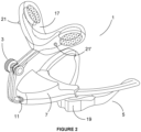
Figure 2 shows an isometric view of a mandibular advancement device showing another preferred form of the present invention. -
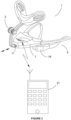
Figure 3 shows an isometric view of a mandibular advancement device showing yet another preferred form of the present invention. -
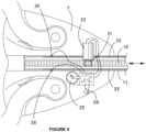
Figure 4 shows a plan view of a preferred form of the invention and shows the electric motor means of adjusting the extraoral portion. -
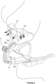
Figure 5 shows an isometric view of a mandibular advancement device showing yet another preferred form of the present invention. - Turning firstly to
Figure 1 , where we are shown an isometric view of amandibular advancement device 1. The device includes anextraoral portion 3 and anintraoral portion 5. Abody portion 7 is at the interface between the two portions and is therefore partly intraoral towards the posterior end and extraoral towards the anterior end. Electric motor means (not visible in this view) are encapsulated within thebody portion 7. Theextraoral portion 3 includes a lowerstraight arm 11 that is adapted to slide into or out of acorresponding opening 13 in the anterior end of thebody portion 7. Thestraight arm 11 may include arack 15 that engages with a pawl on the electric motor to cause the arm to move into or out of thebody portion 7 as shown by the double ended arrow. Arocker switch 9 is formed in the extraoral portion of thebody portion 7 and this is able to control the electric motor means. When theswitch 9 is rocked in a first position, the motorised means act upon thelower arm 11 and forces it to move outwardly, and when therocker switch 9 is rocked to a second position, the motorised means acts upon lower arm and forces it to move into the body portion . The upper portion of theextraoral portion 3 terminates at apad assembly 17. When themandibular advancement device 1 is worn, the pad assembly contacts the subnasal maxillary bone of the wearer. Theupper pad assembly 17 braces against alower pad 19 that is located on theintraoral portion 5 of thedevice 1 and contacts the gingiva and/or teeth of the wearer. The opposing forces applied by thepad assembly 17 and thelower pad 19 combine to adjust the position of the mandible of the wearer. By moving theextraoral portion 3 of thedevice 1, the operator of therocker switch 9 thereby adjusts the force applied upon the subnasal maxillary bone of the wearer, and thereby causes a change in the position of the wearer's mandible. - Now turning to
Figure 2 , where we are shown an alternative embodiment of the present invention. In this embodiment, the rocker switch is removed from thebody portion 7 and is relocated to thepad assembly 15 as a pair ofmomentary switches 21 and 21'. These momentary switches act similarly to therocker switch 9 as shown inFigure 1 . When an operator, perhaps the wearer, depressesmomentary switch 21, the electric motor encapsulated inside thebody portion 7 is activated and causes thelower arm 11 to retract into thebody portion 7, and when the operator depresses momentary switch 21', the electric motor is activated and causes thelower arm 11 to extend out from thebody portion 7. The extraoral portion includes electrical wiring, preferably encapsulated within its body that enables the action of either momentary switch to activate the electric motor means within thebody portion 7. - In
Figure 3 we are shown another preferred embodiment of the present invention. In this embodiment, all mechanical switches are removed from thedevice 1 and the electric motor means are instead controlled wirelessly. In this embodiment, thebody portion 7 includes wireless transmission and receiving means that are adapted to pair with an external computerised device. In this example, asmart phone 21 is shown. Thesmart phone 21 includes an app that is designed to work with thedevice 1. In one mode of the app, the operator can use virtual buttons displayed on the smart phone's 21 screen to cause the electric motor means to move thelower arm 11 into or out of thebody portion 7. - In
Figure 4 , we are shown a plan view of thebody portion 7 in accordance with one embodiment of the present invention. In this view we can see theelectric motor 23 mounted inside the lower half of thebody portion 7. Theelectric motor 23 is powered byrechargeable battery 25. Optionally, the invention may also include logic control means 27. The logic control means may be programmed to provide automatic functionality of thedevice 1. Wireless connectivity may also be included. Thebody portion 7 may also include awireless antenna 29 that enables thedevice 1 to wirelessly connect to an external computerised device. As shown in this view, theelectric motor 23 is fitted with apawl 31 that engages with therack 15 on thelower arm 11. Of course, other arrangements for engagement between theelectric motor 23 and thelower arm 11 are possible and fit within the scope of this invention. Also shown in this view is one preferred option usingelectrical rails 33 and 33' for transmitting electrical signals when momentary switches are included upon the pad assembly. Theelectrical rails 33 and 33' are electrically connected to theslide contacts 35 and 35' - In
Figure 5 , we are shown another embodiment of the present invention. In this embodiment, twoairflow sensors 37 and 37' are located directly below the nostrils of the wearer of the device. As the wearer breathes, thesensors 37 and 37' determine the airflow rate. This data is then fed to the logic control means viawires 39 and 39'. The logic control means are programmed to analyse the airflow data. If the logic control means determine that the flowrate associated with the wearer's breathing has changed sufficiently, then the logic control means are programmed to autonomously engage the electric motor means and adjust the position of the wearer's mandible in an attempt to affect the wearer's breathing and return the rate of airflow back within a set of control limits. The logic control means may also send telemetry wirelessly to an external computerised device. This can be done continuously or in batches. This arrangement makes thedevice 1 completely automatic. Once the nominal breathing rate is determined, and the maximum and minimum control points set, then the device will automatically alter the position of the wearer's mandible in an autonomous attempt to correct undesirable changes in breathing. The telemetry sent to the external computerised device is capable of giving the wearer and other carers and health service professionals valuable insights into the wearer's breathing patterns while using the device. - The device may also include a manual override, as shown in this example as
rocker switch 9 so that a wearer can take manual control of the device. A slider switch may be included on either the body, or the pad assembly that enables a wearer or care giver to switch off the automatic mode of operation. - While the above description includes the preferred embodiments of the invention, it is to be understood that many variations, alterations, modifications and/or additions may be introduced into the constructions and arrangements of parts previously described without departing from the essential features of the invention
- It will be also understood that where the word "comprise", and variations such as "comprises" and "comprising", are used in this specification, unless the context requires otherwise such use is intended to imply the inclusion of a stated feature or features but is not to be taken as excluding the presence of other feature or features.
- The reference to any prior art in this specification is not, and should not be taken as, an acknowledgment or any form of suggestion that such prior art forms part of the common general knowledge.
Claims (12)
- A mandibular advancement device of the type having both intraoral (5) and extraoral portions (3), the extraoral portion (3) including a lower arm (11) that is substantially straight and a curved upper arm that curves upwardly from the lower arm (11) and back towards a face of a wearer of the device, the posterior end of the upper arm including a pad assembly (17) that is adapted to make contact with, and apply pressure to, a subnasal maxillary bone of the wearer,the mandibular advancement device further including:
an adjustment means including a body portion (7) that is at an interface between the intraoral (5) and extraoral (3) portions and thereby is part intraoral and part extraoral, wherein the pad assembly (17) of the device includes sensor means (37,37') that are adapted to sense the airflow emanating from a nose of the wearer as they breathe while wearing the device,characterised by:the body portion (7) including motorised means encapsulated within the body portion (7), a substantial portion of the lower arm (11) being engageable with the motorised means, the motorised means being adapted to engage with the lower arm (11) and cause it to slidably extend from, or slidably retract into, the body portion (7), wherein the lower arm (11) extends directly outwardly from the extraoral part of the body portion;wherein sensor means (37, 37') are also adapted to feed sensor data collected in real time to logic control means (27) contained within the body portion (7); and wherein the logic control means (27) are adapted to process the sensor data they receive to determine if a position of a mandible of the wearer needs adjusting to improve airflow from the wearer, and if so, then the logic control means (27) are adapted to activate the motorised means to either extend or retract the lower arm (11) for an appropriate distance, thereby causing the pad assembly (17) to apply more or less pressure to the subnasal maxillary bone, and thereby change the position of the mandible of the wearer into a new position. - The mandibular advancement device as defined in claim 1 wherein the device includes a manual means adapted to enable manual control of the motorised means.
- The mandibular advancement device as defined in claim 2 wherein the manual means includes a switch that causes the motorised means to slidably extend the lower arm (11) from the body portion (7) when the switch is in a first position, and slidably retract the lower arm (11) into the body portion (7) when the switch is in an opposite position.
- The mandibular advancement device as defined in claim 3 wherein the switch is a rocker switch.
- The mandibular advancement device as defined in claim 3 or 4 wherein the switch is located on the extraoral part of the body portion (7).
- The mandibular advancement device as defined in claim 3 or 4 wherein the switch is located on the pad assembly (17) as a pair of momentary switches, one for retraction and one for extension.
- The mandibular advancement device as defined in claim 2 wherein the manual means includes a portable device, said portable device being wirelessly paired with the logic control means (27), the portable device including an app that includes manual control means that interact with the logic control means (27) and adapted to manually cause the motorised means to either extend or retract the lower arm (11).
- The mandibular advancement device as defined in claim 7 wherein the portable device includes an app that is adapted to enable a user of the device to create an account within the app, the app recording an optimal first position of the extraoral portion of the mandibular advancement device so that when subsequent mandibular advancement devices are paired to the portable device and linked to the account within the app, the app controls the optimal first position of a respective subsequent mandibular advancement device.
- The mandibular advancement device as defined in claim 8 wherein the app links to an account belonging to the wearer of the device, and the account belonging to the wearer is adapted to receive telemetry from the logic control means (27), either in real-time, or in batch mode, and this telemetry is logged for the wearer within their account for subsequent analysis of breathing patterns and movement of the wearer's mandible over a time period.
- The mandibular advancement device as defined in claim 9 wherein the app includes alarm means that are enabled if/when the telemetry is lost from the mandibular advancement device.
- The mandibular advancement device as defined in any one of claims 8 to 10 wherein the app includes alarm means that are enabled if/when a fault within the adjustment means is detected by the logic control means, or if a battery powering the motorised means reaches a pre-set minimum charge.
- A method of adjusting a position of an extraoral portion of a mandibular advancement device, the method including:a) pairing a mandibular advancement device to an account within an app on a portable device;b) waiting for the extraoral portion to move into a first position under control of the app;c) inserting an intraoral portion of the mandibular advancement device within an oral cavity of a wearer;d) ensuring the mandibular advancement device is properly fitted so a pad assembly of the mandibular advancement device makes proper contact with a subnasal maxillary bone of the wearer;e) using a manual adjustment means of the mandibular advancement device to fine tune the mandibular advancement device so that a mandible of the wearer is in its initial optimal position for both comfort and to provide airflow sensors on the pad assembly to sense an optimal based airflow for the wearer at a commencement of their use of the device;f) feeding airflow sensor data from the airflow sensors in real-time to a logic control means of an adjustment means;g) enabling the logic control means to analyse the sensor data to determine if a position of the mandible of the wearer should move, and if it is determined that the mandible should be moved; thenh) allowing the logic control means to operate a motorised means of the adjustment means to either extend or retract a lower arm of the extraoral portion to thereby cause the pad assembly to either exert more or less force upon the subnasal maxillary bone of the wearer, thereby causing the mandible of the wearer to move to a new position.
Applications Claiming Priority (2)
| Application Number | Priority Date | Filing Date | Title |
|---|---|---|---|
| AU2019903108A AU2019903108A0 (en) | 2019-08-26 | Device with Automatic Adjustment Means | |
| PCT/AU2020/000089 WO2021035279A1 (en) | 2019-08-26 | 2020-08-26 | Mandibular advancement device with automatic adjustment means |
Publications (4)
| Publication Number | Publication Date |
|---|---|
| EP4021358A1 EP4021358A1 (en) | 2022-07-06 |
| EP4021358A4 EP4021358A4 (en) | 2023-08-23 |
| EP4021358C0 EP4021358C0 (en) | 2024-12-18 |
| EP4021358B1 true EP4021358B1 (en) | 2024-12-18 |
Family
ID=74683305
Family Applications (1)
| Application Number | Title | Priority Date | Filing Date |
|---|---|---|---|
| EP20858076.1A Active EP4021358B1 (en) | 2019-08-26 | 2020-08-26 | Mandibular advancement device with automatic adjustment means |
Country Status (4)
| Country | Link |
|---|---|
| US (1) | US12383420B2 (en) |
| EP (1) | EP4021358B1 (en) |
| AU (1) | AU2020339848B2 (en) |
| WO (1) | WO2021035279A1 (en) |
Families Citing this family (1)
| Publication number | Priority date | Publication date | Assignee | Title |
|---|---|---|---|---|
| KR102749316B1 (en) * | 2022-10-20 | 2025-01-03 | 주식회사 엠디스테이지 | Sleep breathing disorder relief device and sleep breathing disorder relief system |
Family Cites Families (11)
| Publication number | Priority date | Publication date | Assignee | Title |
|---|---|---|---|---|
| US5678567A (en) | 1994-03-25 | 1997-10-21 | Thornton; W. Keith | Apparatus for adjusting a dental device |
| US5921241A (en) | 1996-03-01 | 1999-07-13 | Belfer; William A. | Anti-snoring device having an adjustable external oral shield |
| US6877513B2 (en) * | 2000-01-21 | 2005-04-12 | Respironics, Inc. | Intraoral apparatus for enhancing airway patency |
| CA2635438C (en) * | 2005-01-10 | 2014-10-21 | Guoping Yan | Method and device for mandibular advancement |
| US10195070B2 (en) | 2012-06-13 | 2019-02-05 | Zst Holdings, Inc. | Methods and apparatuses for performing remote titration of mandibular protrusion |
| US11246743B2 (en) * | 2014-06-04 | 2022-02-15 | Archis Health Investments | System and method for sensor driven intelligent oral appliance |
| US10537463B2 (en) * | 2015-01-13 | 2020-01-21 | Align Technology, Inc. | Systems and methods for positioning a patient's mandible in response to sleep apnea status |
| US20160354231A1 (en) | 2015-06-08 | 2016-12-08 | Airway Technologies, Llc | Device and system for improved breathing |
| KR101784416B1 (en) | 2016-12-15 | 2017-11-06 | 연세대학교 산학협력단 | Apparatus for preventing of snoring and sleep apnea |
| EP3694400A4 (en) * | 2017-10-13 | 2021-07-28 | Bioanalytics Holdings Pty Ltd | SLEEP MONITORING ADVANCEMENTS |
| CN109602534A (en) | 2019-01-15 | 2019-04-12 | 兴康明科技(深圳)有限公司 | A mandibular advancement snoring device with intelligent automatic adjustment |
-
2020
- 2020-08-26 WO PCT/AU2020/000089 patent/WO2021035279A1/en not_active Ceased
- 2020-08-26 US US17/638,691 patent/US12383420B2/en active Active
- 2020-08-26 EP EP20858076.1A patent/EP4021358B1/en active Active
- 2020-08-26 AU AU2020339848A patent/AU2020339848B2/en active Active
Also Published As
| Publication number | Publication date |
|---|---|
| EP4021358C0 (en) | 2024-12-18 |
| US12383420B2 (en) | 2025-08-12 |
| EP4021358A4 (en) | 2023-08-23 |
| AU2020339848A1 (en) | 2022-03-10 |
| EP4021358A1 (en) | 2022-07-06 |
| WO2021035279A1 (en) | 2021-03-04 |
| US20230023562A1 (en) | 2023-01-26 |
| AU2020339848B2 (en) | 2025-11-27 |
Similar Documents
| Publication | Publication Date | Title |
|---|---|---|
| JP7437316B2 (en) | Mandibular anterior fixation device with a set of separated electrical components | |
| KR101784416B1 (en) | Apparatus for preventing of snoring and sleep apnea | |
| CN113571151A (en) | Device and method for monitoring orofacial muscle training | |
| US12376987B2 (en) | Dynamic mandibular and lingual repositioning devices, controller station, and methods of treating and/or diagnosing medical disorders | |
| KR101929187B1 (en) | Exercisers for temporomandibular training | |
| CN109789031B (en) | Dental appliance for sleep apnea, snoring and tongue and mouth remodeling | |
| JP7053651B2 (en) | How to adjust the dimensions of the mandibular anterior fixation device and the connecting assembly of the mandibular anterior fixation device | |
| CN109602534A (en) | A mandibular advancement snoring device with intelligent automatic adjustment | |
| KR102222694B1 (en) | Wearable oral system and method of adjusting position of soft-palate and tongue | |
| US12383420B2 (en) | Mandibular advancement device with automatic adjustment means | |
| US20200330261A1 (en) | System and method for treating bruxism | |
| KR20200060715A (en) | Sensors and systems for monitoring the wearing duration of orthodontic elastic materials | |
| CN104434356A (en) | Intelligent braces | |
| US20180199857A1 (en) | Antisnoring device | |
| CN209827186U (en) | Mandibular advancement snore preventing device with intelligent automatic adjustment function | |
| US20240066291A1 (en) | Orthodontic devices and systems and methods for using such devices | |
| KR101911279B1 (en) | Apparatus for preventing of snoring and sleep apnea | |
| KR101640154B1 (en) | Apparatus for preventing aspiration of patient with dysphagia | |
| CN102949771B (en) | Noninvasive synchronous breathing airway opener | |
| CN219461453U (en) | Oral appliance | |
| US20220330888A1 (en) | Accessories for a mandible advancement device | |
| EP4193958A1 (en) | Dental orthodontic accelerator | |
| CN211934490U (en) | Tongue back elastic traction adjusting titration apparatus | |
| CN215900620U (en) | Wearable intelligent open airway and oxygen supply device | |
| CN120616815A (en) | Invisible appliance based on electromagnet principle |
Legal Events
| Date | Code | Title | Description |
|---|---|---|---|
| STAA | Information on the status of an ep patent application or granted ep patent |
Free format text: STATUS: THE INTERNATIONAL PUBLICATION HAS BEEN MADE |
|
| PUAI | Public reference made under article 153(3) epc to a published international application that has entered the european phase |
Free format text: ORIGINAL CODE: 0009012 |
|
| STAA | Information on the status of an ep patent application or granted ep patent |
Free format text: STATUS: REQUEST FOR EXAMINATION WAS MADE |
|
| 17P | Request for examination filed |
Effective date: 20220325 |
|
| AK | Designated contracting states |
Kind code of ref document: A1 Designated state(s): AL AT BE BG CH CY CZ DE DK EE ES FI FR GB GR HR HU IE IS IT LI LT LU LV MC MK MT NL NO PL PT RO RS SE SI SK SM TR |
|
| DAV | Request for validation of the european patent (deleted) | ||
| DAX | Request for extension of the european patent (deleted) | ||
| A4 | Supplementary search report drawn up and despatched |
Effective date: 20230721 |
|
| RIC1 | Information provided on ipc code assigned before grant |
Ipc: A61F 5/56 20060101AFI20230717BHEP |
|
| GRAP | Despatch of communication of intention to grant a patent |
Free format text: ORIGINAL CODE: EPIDOSNIGR1 |
|
| STAA | Information on the status of an ep patent application or granted ep patent |
Free format text: STATUS: GRANT OF PATENT IS INTENDED |
|
| INTG | Intention to grant announced |
Effective date: 20240510 |
|
| GRAJ | Information related to disapproval of communication of intention to grant by the applicant or resumption of examination proceedings by the epo deleted |
Free format text: ORIGINAL CODE: EPIDOSDIGR1 |
|
| STAA | Information on the status of an ep patent application or granted ep patent |
Free format text: STATUS: REQUEST FOR EXAMINATION WAS MADE |
|
| GRAP | Despatch of communication of intention to grant a patent |
Free format text: ORIGINAL CODE: EPIDOSNIGR1 |
|
| STAA | Information on the status of an ep patent application or granted ep patent |
Free format text: STATUS: GRANT OF PATENT IS INTENDED |
|
| INTC | Intention to grant announced (deleted) | ||
| INTG | Intention to grant announced |
Effective date: 20240916 |
|
| GRAS | Grant fee paid |
Free format text: ORIGINAL CODE: EPIDOSNIGR3 |
|
| GRAA | (expected) grant |
Free format text: ORIGINAL CODE: 0009210 |
|
| STAA | Information on the status of an ep patent application or granted ep patent |
Free format text: STATUS: THE PATENT HAS BEEN GRANTED |
|
| AK | Designated contracting states |
Kind code of ref document: B1 Designated state(s): AL AT BE BG CH CY CZ DE DK EE ES FI FR GB GR HR HU IE IS IT LI LT LU LV MC MK MT NL NO PL PT RO RS SE SI SK SM TR |
|
| REG | Reference to a national code |
Ref country code: CH Ref legal event code: EP |
|
| REG | Reference to a national code |
Ref country code: DE Ref legal event code: R096 Ref document number: 602020043486 Country of ref document: DE |
|
| REG | Reference to a national code |
Ref country code: IE Ref legal event code: FG4D |
|
| U01 | Request for unitary effect filed |
Effective date: 20241230 |
|
| U07 | Unitary effect registered |
Designated state(s): AT BE BG DE DK EE FI FR IT LT LU LV MT NL PT RO SE SI Effective date: 20250114 |
|
| PG25 | Lapsed in a contracting state [announced via postgrant information from national office to epo] |
Ref country code: HR Free format text: LAPSE BECAUSE OF FAILURE TO SUBMIT A TRANSLATION OF THE DESCRIPTION OR TO PAY THE FEE WITHIN THE PRESCRIBED TIME-LIMIT Effective date: 20241218 |
|
| PG25 | Lapsed in a contracting state [announced via postgrant information from national office to epo] |
Ref country code: GR Free format text: LAPSE BECAUSE OF FAILURE TO SUBMIT A TRANSLATION OF THE DESCRIPTION OR TO PAY THE FEE WITHIN THE PRESCRIBED TIME-LIMIT Effective date: 20250319 |
|
| PG25 | Lapsed in a contracting state [announced via postgrant information from national office to epo] |
Ref country code: RS Free format text: LAPSE BECAUSE OF FAILURE TO SUBMIT A TRANSLATION OF THE DESCRIPTION OR TO PAY THE FEE WITHIN THE PRESCRIBED TIME-LIMIT Effective date: 20250318 |
|
| U1N | Appointed representative for the unitary patent procedure changed after the registration of the unitary effect |
Representative=s name: METIDA; LT |
|
| PG25 | Lapsed in a contracting state [announced via postgrant information from national office to epo] |
Ref country code: SM Free format text: LAPSE BECAUSE OF FAILURE TO SUBMIT A TRANSLATION OF THE DESCRIPTION OR TO PAY THE FEE WITHIN THE PRESCRIBED TIME-LIMIT Effective date: 20241218 |
|
| PG25 | Lapsed in a contracting state [announced via postgrant information from national office to epo] |
Ref country code: PL Free format text: LAPSE BECAUSE OF FAILURE TO SUBMIT A TRANSLATION OF THE DESCRIPTION OR TO PAY THE FEE WITHIN THE PRESCRIBED TIME-LIMIT Effective date: 20241218 |
|
| PG25 | Lapsed in a contracting state [announced via postgrant information from national office to epo] |
Ref country code: ES Free format text: LAPSE BECAUSE OF FAILURE TO SUBMIT A TRANSLATION OF THE DESCRIPTION OR TO PAY THE FEE WITHIN THE PRESCRIBED TIME-LIMIT Effective date: 20241218 |
|
| PG25 | Lapsed in a contracting state [announced via postgrant information from national office to epo] |
Ref country code: IS Free format text: LAPSE BECAUSE OF FAILURE TO SUBMIT A TRANSLATION OF THE DESCRIPTION OR TO PAY THE FEE WITHIN THE PRESCRIBED TIME-LIMIT Effective date: 20250418 |
|
| PG25 | Lapsed in a contracting state [announced via postgrant information from national office to epo] |
Ref country code: SK Free format text: LAPSE BECAUSE OF FAILURE TO SUBMIT A TRANSLATION OF THE DESCRIPTION OR TO PAY THE FEE WITHIN THE PRESCRIBED TIME-LIMIT Effective date: 20241218 |
|
| PG25 | Lapsed in a contracting state [announced via postgrant information from national office to epo] |
Ref country code: CZ Free format text: LAPSE BECAUSE OF FAILURE TO SUBMIT A TRANSLATION OF THE DESCRIPTION OR TO PAY THE FEE WITHIN THE PRESCRIBED TIME-LIMIT Effective date: 20241218 |
|
| U20 | Renewal fee for the european patent with unitary effect paid |
Year of fee payment: 6 Effective date: 20250822 |
|
| PGFP | Annual fee paid to national office [announced via postgrant information from national office to epo] |
Ref country code: NO Payment date: 20250828 Year of fee payment: 6 |
|
| PGFP | Annual fee paid to national office [announced via postgrant information from national office to epo] |
Ref country code: GB Payment date: 20250822 Year of fee payment: 6 |
|
| PLBE | No opposition filed within time limit |
Free format text: ORIGINAL CODE: 0009261 |
|
| STAA | Information on the status of an ep patent application or granted ep patent |
Free format text: STATUS: NO OPPOSITION FILED WITHIN TIME LIMIT |
|
| REG | Reference to a national code |
Ref country code: CH Ref legal event code: L10 Free format text: ST27 STATUS EVENT CODE: U-0-0-L10-L00 (AS PROVIDED BY THE NATIONAL OFFICE) Effective date: 20251029 |
|
| 26N | No opposition filed |
Effective date: 20250919 |
|
| REG | Reference to a national code |
Ref country code: CH Ref legal event code: H13 Free format text: ST27 STATUS EVENT CODE: U-0-0-H10-H13 (AS PROVIDED BY THE NATIONAL OFFICE) Effective date: 20260324 |
|
| PG25 | Lapsed in a contracting state [announced via postgrant information from national office to epo] |
Ref country code: MC Free format text: LAPSE BECAUSE OF FAILURE TO SUBMIT A TRANSLATION OF THE DESCRIPTION OR TO PAY THE FEE WITHIN THE PRESCRIBED TIME-LIMIT Effective date: 20241218 |
|
| PG25 | Lapsed in a contracting state [announced via postgrant information from national office to epo] |
Ref country code: CH Free format text: LAPSE BECAUSE OF NON-PAYMENT OF DUE FEES Effective date: 20250831 |