EP4021353B1 - Bodenkontaktsensoranordnung für unterschenkelprothese und orthesen - Google Patents
Bodenkontaktsensoranordnung für unterschenkelprothese und orthesen Download PDFInfo
- Publication number
- EP4021353B1 EP4021353B1 EP20761029.6A EP20761029A EP4021353B1 EP 4021353 B1 EP4021353 B1 EP 4021353B1 EP 20761029 A EP20761029 A EP 20761029A EP 4021353 B1 EP4021353 B1 EP 4021353B1
- Authority
- EP
- European Patent Office
- Prior art keywords
- sensors
- ground
- prosthetic device
- sensor array
- sensor
- Prior art date
- Legal status (The legal status is an assumption and is not a legal conclusion. Google has not performed a legal analysis and makes no representation as to the accuracy of the status listed.)
- Active
Links
Images


Classifications
-
- A—HUMAN NECESSITIES
- A61—MEDICAL OR VETERINARY SCIENCE; HYGIENE
- A61F—FILTERS IMPLANTABLE INTO BLOOD VESSELS; PROSTHESES; DEVICES PROVIDING PATENCY TO, OR PREVENTING COLLAPSING OF, TUBULAR STRUCTURES OF THE BODY, e.g. STENTS; ORTHOPAEDIC, NURSING OR CONTRACEPTIVE DEVICES; FOMENTATION; TREATMENT OR PROTECTION OF EYES OR EARS; BANDAGES, DRESSINGS OR ABSORBENT PADS; FIRST-AID KITS
- A61F2/00—Filters implantable into blood vessels; Prostheses, i.e. artificial substitutes or replacements for parts of the body; Appliances for connecting them with the body; Devices providing patency to, or preventing collapsing of, tubular structures of the body, e.g. stents
- A61F2/50—Prostheses not implantable in the body
- A61F2/76—Means for assembling, fitting or testing prostheses, e.g. for measuring or balancing, e.g. alignment means
-
- A—HUMAN NECESSITIES
- A61—MEDICAL OR VETERINARY SCIENCE; HYGIENE
- A61F—FILTERS IMPLANTABLE INTO BLOOD VESSELS; PROSTHESES; DEVICES PROVIDING PATENCY TO, OR PREVENTING COLLAPSING OF, TUBULAR STRUCTURES OF THE BODY, e.g. STENTS; ORTHOPAEDIC, NURSING OR CONTRACEPTIVE DEVICES; FOMENTATION; TREATMENT OR PROTECTION OF EYES OR EARS; BANDAGES, DRESSINGS OR ABSORBENT PADS; FIRST-AID KITS
- A61F2/00—Filters implantable into blood vessels; Prostheses, i.e. artificial substitutes or replacements for parts of the body; Appliances for connecting them with the body; Devices providing patency to, or preventing collapsing of, tubular structures of the body, e.g. stents
- A61F2/50—Prostheses not implantable in the body
- A61F2/60—Artificial legs or feet or parts thereof
- A61F2/64—Knee joints
-
- A—HUMAN NECESSITIES
- A61—MEDICAL OR VETERINARY SCIENCE; HYGIENE
- A61F—FILTERS IMPLANTABLE INTO BLOOD VESSELS; PROSTHESES; DEVICES PROVIDING PATENCY TO, OR PREVENTING COLLAPSING OF, TUBULAR STRUCTURES OF THE BODY, e.g. STENTS; ORTHOPAEDIC, NURSING OR CONTRACEPTIVE DEVICES; FOMENTATION; TREATMENT OR PROTECTION OF EYES OR EARS; BANDAGES, DRESSINGS OR ABSORBENT PADS; FIRST-AID KITS
- A61F2/00—Filters implantable into blood vessels; Prostheses, i.e. artificial substitutes or replacements for parts of the body; Appliances for connecting them with the body; Devices providing patency to, or preventing collapsing of, tubular structures of the body, e.g. stents
- A61F2/50—Prostheses not implantable in the body
- A61F2/60—Artificial legs or feet or parts thereof
- A61F2/66—Feet; Ankle joints
- A61F2/6607—Ankle joints
-
- A—HUMAN NECESSITIES
- A61—MEDICAL OR VETERINARY SCIENCE; HYGIENE
- A61F—FILTERS IMPLANTABLE INTO BLOOD VESSELS; PROSTHESES; DEVICES PROVIDING PATENCY TO, OR PREVENTING COLLAPSING OF, TUBULAR STRUCTURES OF THE BODY, e.g. STENTS; ORTHOPAEDIC, NURSING OR CONTRACEPTIVE DEVICES; FOMENTATION; TREATMENT OR PROTECTION OF EYES OR EARS; BANDAGES, DRESSINGS OR ABSORBENT PADS; FIRST-AID KITS
- A61F2/00—Filters implantable into blood vessels; Prostheses, i.e. artificial substitutes or replacements for parts of the body; Appliances for connecting them with the body; Devices providing patency to, or preventing collapsing of, tubular structures of the body, e.g. stents
- A61F2/50—Prostheses not implantable in the body
- A61F2/68—Operating or control means
- A61F2/70—Operating or control means electrical
-
- A—HUMAN NECESSITIES
- A61—MEDICAL OR VETERINARY SCIENCE; HYGIENE
- A61F—FILTERS IMPLANTABLE INTO BLOOD VESSELS; PROSTHESES; DEVICES PROVIDING PATENCY TO, OR PREVENTING COLLAPSING OF, TUBULAR STRUCTURES OF THE BODY, e.g. STENTS; ORTHOPAEDIC, NURSING OR CONTRACEPTIVE DEVICES; FOMENTATION; TREATMENT OR PROTECTION OF EYES OR EARS; BANDAGES, DRESSINGS OR ABSORBENT PADS; FIRST-AID KITS
- A61F2/00—Filters implantable into blood vessels; Prostheses, i.e. artificial substitutes or replacements for parts of the body; Appliances for connecting them with the body; Devices providing patency to, or preventing collapsing of, tubular structures of the body, e.g. stents
- A61F2/50—Prostheses not implantable in the body
- A61F2002/5016—Prostheses not implantable in the body adjustable
- A61F2002/503—Prostheses not implantable in the body adjustable for adjusting elasticity, flexibility, spring rate or mechanical tension
-
- A—HUMAN NECESSITIES
- A61—MEDICAL OR VETERINARY SCIENCE; HYGIENE
- A61F—FILTERS IMPLANTABLE INTO BLOOD VESSELS; PROSTHESES; DEVICES PROVIDING PATENCY TO, OR PREVENTING COLLAPSING OF, TUBULAR STRUCTURES OF THE BODY, e.g. STENTS; ORTHOPAEDIC, NURSING OR CONTRACEPTIVE DEVICES; FOMENTATION; TREATMENT OR PROTECTION OF EYES OR EARS; BANDAGES, DRESSINGS OR ABSORBENT PADS; FIRST-AID KITS
- A61F2/00—Filters implantable into blood vessels; Prostheses, i.e. artificial substitutes or replacements for parts of the body; Appliances for connecting them with the body; Devices providing patency to, or preventing collapsing of, tubular structures of the body, e.g. stents
- A61F2/50—Prostheses not implantable in the body
- A61F2002/5081—Additional features
- A61F2002/5083—Additional features modular
-
- A—HUMAN NECESSITIES
- A61—MEDICAL OR VETERINARY SCIENCE; HYGIENE
- A61F—FILTERS IMPLANTABLE INTO BLOOD VESSELS; PROSTHESES; DEVICES PROVIDING PATENCY TO, OR PREVENTING COLLAPSING OF, TUBULAR STRUCTURES OF THE BODY, e.g. STENTS; ORTHOPAEDIC, NURSING OR CONTRACEPTIVE DEVICES; FOMENTATION; TREATMENT OR PROTECTION OF EYES OR EARS; BANDAGES, DRESSINGS OR ABSORBENT PADS; FIRST-AID KITS
- A61F2/00—Filters implantable into blood vessels; Prostheses, i.e. artificial substitutes or replacements for parts of the body; Appliances for connecting them with the body; Devices providing patency to, or preventing collapsing of, tubular structures of the body, e.g. stents
- A61F2/50—Prostheses not implantable in the body
- A61F2/60—Artificial legs or feet or parts thereof
- A61F2/66—Feet; Ankle joints
- A61F2002/6614—Feet
-
- A—HUMAN NECESSITIES
- A61—MEDICAL OR VETERINARY SCIENCE; HYGIENE
- A61F—FILTERS IMPLANTABLE INTO BLOOD VESSELS; PROSTHESES; DEVICES PROVIDING PATENCY TO, OR PREVENTING COLLAPSING OF, TUBULAR STRUCTURES OF THE BODY, e.g. STENTS; ORTHOPAEDIC, NURSING OR CONTRACEPTIVE DEVICES; FOMENTATION; TREATMENT OR PROTECTION OF EYES OR EARS; BANDAGES, DRESSINGS OR ABSORBENT PADS; FIRST-AID KITS
- A61F2/00—Filters implantable into blood vessels; Prostheses, i.e. artificial substitutes or replacements for parts of the body; Appliances for connecting them with the body; Devices providing patency to, or preventing collapsing of, tubular structures of the body, e.g. stents
- A61F2/50—Prostheses not implantable in the body
- A61F2/68—Operating or control means
- A61F2002/6827—Feedback system for providing user sensation, e.g. by force, contact or position
-
- A—HUMAN NECESSITIES
- A61—MEDICAL OR VETERINARY SCIENCE; HYGIENE
- A61F—FILTERS IMPLANTABLE INTO BLOOD VESSELS; PROSTHESES; DEVICES PROVIDING PATENCY TO, OR PREVENTING COLLAPSING OF, TUBULAR STRUCTURES OF THE BODY, e.g. STENTS; ORTHOPAEDIC, NURSING OR CONTRACEPTIVE DEVICES; FOMENTATION; TREATMENT OR PROTECTION OF EYES OR EARS; BANDAGES, DRESSINGS OR ABSORBENT PADS; FIRST-AID KITS
- A61F2/00—Filters implantable into blood vessels; Prostheses, i.e. artificial substitutes or replacements for parts of the body; Appliances for connecting them with the body; Devices providing patency to, or preventing collapsing of, tubular structures of the body, e.g. stents
- A61F2/50—Prostheses not implantable in the body
- A61F2/68—Operating or control means
- A61F2/70—Operating or control means electrical
- A61F2002/701—Operating or control means electrical operated by electrically controlled means, e.g. solenoids or torque motors
-
- A—HUMAN NECESSITIES
- A61—MEDICAL OR VETERINARY SCIENCE; HYGIENE
- A61F—FILTERS IMPLANTABLE INTO BLOOD VESSELS; PROSTHESES; DEVICES PROVIDING PATENCY TO, OR PREVENTING COLLAPSING OF, TUBULAR STRUCTURES OF THE BODY, e.g. STENTS; ORTHOPAEDIC, NURSING OR CONTRACEPTIVE DEVICES; FOMENTATION; TREATMENT OR PROTECTION OF EYES OR EARS; BANDAGES, DRESSINGS OR ABSORBENT PADS; FIRST-AID KITS
- A61F2/00—Filters implantable into blood vessels; Prostheses, i.e. artificial substitutes or replacements for parts of the body; Appliances for connecting them with the body; Devices providing patency to, or preventing collapsing of, tubular structures of the body, e.g. stents
- A61F2/50—Prostheses not implantable in the body
- A61F2/68—Operating or control means
- A61F2/70—Operating or control means electrical
- A61F2002/704—Operating or control means electrical computer-controlled, e.g. robotic control
-
- A—HUMAN NECESSITIES
- A61—MEDICAL OR VETERINARY SCIENCE; HYGIENE
- A61F—FILTERS IMPLANTABLE INTO BLOOD VESSELS; PROSTHESES; DEVICES PROVIDING PATENCY TO, OR PREVENTING COLLAPSING OF, TUBULAR STRUCTURES OF THE BODY, e.g. STENTS; ORTHOPAEDIC, NURSING OR CONTRACEPTIVE DEVICES; FOMENTATION; TREATMENT OR PROTECTION OF EYES OR EARS; BANDAGES, DRESSINGS OR ABSORBENT PADS; FIRST-AID KITS
- A61F2/00—Filters implantable into blood vessels; Prostheses, i.e. artificial substitutes or replacements for parts of the body; Appliances for connecting them with the body; Devices providing patency to, or preventing collapsing of, tubular structures of the body, e.g. stents
- A61F2/50—Prostheses not implantable in the body
- A61F2/76—Means for assembling, fitting or testing prostheses, e.g. for measuring or balancing, e.g. alignment means
- A61F2002/7615—Measuring means
- A61F2002/762—Measuring means for measuring dimensions, e.g. a distance
-
- A—HUMAN NECESSITIES
- A61—MEDICAL OR VETERINARY SCIENCE; HYGIENE
- A61F—FILTERS IMPLANTABLE INTO BLOOD VESSELS; PROSTHESES; DEVICES PROVIDING PATENCY TO, OR PREVENTING COLLAPSING OF, TUBULAR STRUCTURES OF THE BODY, e.g. STENTS; ORTHOPAEDIC, NURSING OR CONTRACEPTIVE DEVICES; FOMENTATION; TREATMENT OR PROTECTION OF EYES OR EARS; BANDAGES, DRESSINGS OR ABSORBENT PADS; FIRST-AID KITS
- A61F2/00—Filters implantable into blood vessels; Prostheses, i.e. artificial substitutes or replacements for parts of the body; Appliances for connecting them with the body; Devices providing patency to, or preventing collapsing of, tubular structures of the body, e.g. stents
- A61F2/50—Prostheses not implantable in the body
- A61F2/76—Means for assembling, fitting or testing prostheses, e.g. for measuring or balancing, e.g. alignment means
- A61F2002/7615—Measuring means
- A61F2002/7625—Measuring means for measuring angular position
-
- A—HUMAN NECESSITIES
- A61—MEDICAL OR VETERINARY SCIENCE; HYGIENE
- A61F—FILTERS IMPLANTABLE INTO BLOOD VESSELS; PROSTHESES; DEVICES PROVIDING PATENCY TO, OR PREVENTING COLLAPSING OF, TUBULAR STRUCTURES OF THE BODY, e.g. STENTS; ORTHOPAEDIC, NURSING OR CONTRACEPTIVE DEVICES; FOMENTATION; TREATMENT OR PROTECTION OF EYES OR EARS; BANDAGES, DRESSINGS OR ABSORBENT PADS; FIRST-AID KITS
- A61F2/00—Filters implantable into blood vessels; Prostheses, i.e. artificial substitutes or replacements for parts of the body; Appliances for connecting them with the body; Devices providing patency to, or preventing collapsing of, tubular structures of the body, e.g. stents
- A61F2/50—Prostheses not implantable in the body
- A61F2/76—Means for assembling, fitting or testing prostheses, e.g. for measuring or balancing, e.g. alignment means
- A61F2002/7615—Measuring means
- A61F2002/764—Measuring means for measuring acceleration
-
- A—HUMAN NECESSITIES
- A61—MEDICAL OR VETERINARY SCIENCE; HYGIENE
- A61F—FILTERS IMPLANTABLE INTO BLOOD VESSELS; PROSTHESES; DEVICES PROVIDING PATENCY TO, OR PREVENTING COLLAPSING OF, TUBULAR STRUCTURES OF THE BODY, e.g. STENTS; ORTHOPAEDIC, NURSING OR CONTRACEPTIVE DEVICES; FOMENTATION; TREATMENT OR PROTECTION OF EYES OR EARS; BANDAGES, DRESSINGS OR ABSORBENT PADS; FIRST-AID KITS
- A61F2/00—Filters implantable into blood vessels; Prostheses, i.e. artificial substitutes or replacements for parts of the body; Appliances for connecting them with the body; Devices providing patency to, or preventing collapsing of, tubular structures of the body, e.g. stents
- A61F2/50—Prostheses not implantable in the body
- A61F2/76—Means for assembling, fitting or testing prostheses, e.g. for measuring or balancing, e.g. alignment means
- A61F2002/7615—Measuring means
- A61F2002/7645—Measuring means for measuring torque, e.g. hinge or turning moment, moment of force
Definitions
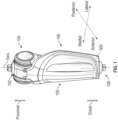
- the present disclosure is related to prosthetic or orthotic systems, in particular to systems and methods for a ground contact sensor array having one or more sensors to detect load applied to a lower-limb prosthetic or orthotic device for controlling the lower-limb prosthetic or orthotic.
- US 2008/276725 A1 discloses a sensor assembly that is provided for measuring forces and/or torques which are transmitted by means of a rigid transmitter having a first part and a second part.
- the sensor assembly includes a first connection, a second connection, electromechanical sensor elements, a first flange, a second flange and a plurality of struts.
- the first and second connections are connectable to the first and second parts of the transmitter, respectively.
- the electromechanical sensor elements convert mechanical parameters into electrical parameters.
- the first flange surrounds the first connection and originates at the first connection.
- the second flange is aligned substantially parallel to the first flange.
- the second connection is arranged on the second flange and has a first surface and a second surface.
- the plurality of struts are substantially perpendicular to the first flange and connect the first flange to the second flange.
- a gap is formed between the first flange, the second flange and the struts, and is larger than a width of the struts.
- the electromechanical sensor elements are designed for determining strains or compressions and are arranged next to the plurality of struts on at least one of the first and second surfaces of the second flange.
- US 2012/083901 A1 discloses prosthetic and/or orthotic devices (PODS), control systems for PODS and methods for controlling PODS.
- PODS prosthetic and/or orthotic devices
- an inference layer collects data regarding a vertical and horizontal displacement of the POD, as well as an angle of the POD with respect to gravity during a gait cycle of a user of the POD.
- a processor analyzes the data collected to determine a locomotion activity of the user and selects one or more control parameters based on the locomotion activity.
- the inference layer may be situated between a reactive layer control module and a learning layer control module of the control system architecture.
- EP 3 128 958 A1 discloses a prosthetic foot that can include an attachment member, at least one first brace, at least one first flexible member, an unpowered actuator, at least one second brace, and at least one second flexible member.
- the attachment member can include a connector configured to connect the attachment member to a user or another prosthetic device.
- the at least one first brace can mount to the attachment member and the at least one first flexible member can connect to the attachment member by the at least one first brace such that a force between the ground and the attachment member can be supported by the at least one first flexible member.
- the unpowered actuator can mount to the attachment member and the at least one second brace can be mounted to the actuator.
- the at least one second flexible member can connect to the attachment member by the at least one second brace such that a force between the ground and the attachment member can be supported by the at least one second flexible member.
- a sensor array for the lower-limb POD may include two or more sensors, which may be non-contact displacement sensors, that can determine a change in distance between a moving part and a non-moving part of the lower-limb POD.
- a moving part or a non-moving part of the POD may support the sensors.
- Ground contact with the lower-limb POD may cause the offset distance between the moving part and the non-moving part to change. For instance, the distance from each of the sensors to respective target portions of the other body, such as respective portions of the moving body, respective magnets, or other respective targets, may be detected by the sensors.
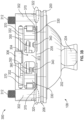
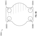
- the sensor assembly 300 includes a structural support 301.
- the structural support 301 may include a frame 302 and beam structures 304 and 305.
- the structural support 301 may include one or more first fasteners 306, one or more backing plates 308A, 308B, and/or one or more second fasteners 312.
- a portion of the structural support 301 is attached to a shank portion of the prosthetic device 100, such as the body 106, such that there is no relative movement between that portion of the structural support 301 and the shank portion, as further described.
- the base 200 is suspended from the structural support 301, such as from the beam structures 304, 305, of the sensor assembly 300. Since the beam structures 304, 305 may be compliant and thus flex when load is applied in the distal-proximal direction, additional structures may be provided to limit the effects of loads causing a distal pull on the base 200.
- the backing plates 330 may attach to the shank of the prosthetic device 100 and to the base 200. The backing plates 330 may be connected to the shank and/or base 200 via fasteners 332. Connection of the base 200 with the shank may prevent or limit the sensor assembly 300 and the base 200 of the distal connector 108 from moving in a distal direction. The backing plates 330 may thus limit displacement of the base 200 under distal pull forces.
- the backing plates 308A, 308B and the corresponding fasteners 312 may be provided in the medial and/or lateral areas of the sensor assembly 300.
- the backing plates 308A, 308B may be symmetrically positioned with respect to the sagittal plane and/or the frontal plane.
- At least a portion of the base 200 includes a magnetic element that can generate a magnetic field around the sensor assembly 300.
- a top surface of the base 200 facing the sensors 350 can be magnetic.
- at least a portion of the beam structures 304, 305 or the mating surface 202 can be magnetic such that the sensors 350 can detect changes in the magnitude of a magnetic field generated by the beam structures 304, 305 or the mating surface 202 under different load conditions.
- the sensors 350 may be positioned such that they are an initial offset distance apart from the base 200 when no load is applied to the prosthetic leg by the ground.
- the initial distance between the base 200 and the sensors 350 may represent a zero-load condition.
- the load may cause relative movement between the base 200 and the frame 302 of the support structure 301 of the sensor assembly 300, thereby changing the offset distance between the base 200 and the sensors 350.
- the change in the distance between the base 200 and the sensors 350 may directly correspond to the amount of load applied to the prosthetic device 100.
- the change in distance will produce a change in voltage generated by the non-contact sensors, which can be analyzed to determine ground contact, as further described.
- the beam structures 304 and/or 305 of the sensor assembly 300 may be compressed at least in an axial direction to reduce the distance between the base 200 and the sensors 350.
- the magnets 340 may move proximally.
- the change in proximity of the magnets 340 and the sensors 350 may change the strength of the magnetic field surrounding the sensors 350.
- reduced distance between the magnets 340 and sensors 350 may increase the magnitude of the magnetic field detected by the sensors 350.
- the increase in the magnitude of the magnetic field detected by the sensors 350 may represent the change in the distance between the magnets340 and the sensors 350, which may represent the change in the distance between the sensor assembly 300 and the base 200, which may be analyzed to determine the presence and/or characteristics of ground contact by the prosthetic device.
- the sensors 350 may generate signals corresponding to the change of the magnetic field.
- the sensors 350 may detect changes in the amount of current or voltage generated by the sensors 350 due to the magnetic field generated by the magnets 340.
- the changes in distance detected by the sensors 350 may be caused by axial translation movement of the base 200 relative to the structure 301, by transverse translational movement of the base 200 relative to the structure 301, and/or by rotational movement of the base 200 relative to the structure 301 about any three orthogonal axes.
- the beam structures 304, 305 of the sensor assembly 300 may allow selective compliance under different load conditions. While the beam structure 304 may be compliant to an axial load (distal-proximal direction), it may be relatively more rigid or less compliant to loads in the anterior-posterior and/or medial-lateral directions. The degree of compliance of the beam structure 304 may be varied by changing various dimensions of the beam structure 304.
- the selective compliance of the support structure 301 and the array of the sensors 350 allow for more accurate detection of loads due to ground contact.
- the separation distance between axially opposing beams 370 provides rigidity in response to sagittal plane torque loads.
- the sensors 350 are less likely to move or to move as much due to such loads, which may be applied due to influences other than ground contact, such as inertial loads during swing phase. Therefore axial loads during stance phase due to ground contact are better isolated and detected. This results in less complex signal processing as compared to other approaches, as discussed herein.
- the configuration of the support structure 301 and base 200 allow for relative movement between the two structures. Since the support structure 301 may be rigidly attached to the shank or other portion of the prosthetic device 100, movement of the base 200 as detected by the sensors 350 corresponds to relative movement between the base 200 and supports structure 301. Thus the resulting voltage changes detected by the sensors 350 is indicative of the relative movement of the respective structures.
- the layout of multiple sensors 350 in an array with such structural configurations can result in robust and reliable output data.
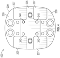
- Figure 4 illustrates an example array 400 of the magnets 340.
- the magnets 340 may be coupled to the base 200 of the distal connector 208. There may be four magnets 340 coupled to the base 200 as shown in Figure 4 . In some aspects, there may be less than four magnets 340 coupled to be base 200. In other aspects, there may be more than four magnets 340 coupled to the base 200.
- the magnets 340 may be arranged in symmetry with respect to the sagittal plane and/or coronal plane. The magnets 340 may be in symmetry with respect to any other planes. In some aspects the magnets 340 may be arranged in point symmetry with respect to a predetermined location of the sensor assembly 300 or the base 200.
- the magnets 340 may be positioned equidistant from each other.
- the magnets 340 may be positioned in a square array (as shown in Figure 4 ), a rectangular array, a circular array, an oval array, a hexagonal array, and the like.
- the magnets 340 can be integrated with the base 200.
- the base 200 can be made out of magnetic material such that at least a portion of the base 200 is magnetic and generates a magnetic field around the sensor assembly 300.
- Figure 5A illustrates an example array 500 of the sensors 350 coupled to the PCB 400.
- the sensors 350F and 350G may be positioned in the anterior portion of the PCB while the sensors 350A and 350B may be positioned in the posterior portion of the PCB.
- the sensors 350C, 350D, and 350E may be positioned between the rest of the sensors (that is, sensors 350A, 350B, 350F, and 350G).
- the sensors may be in symmetry with respect to the sagittal plane that bisects the sensor assembly 300 into a medial side and a lateral side.
- the sagittal plane may extend between the front side and the rear side through the sensor 350D.
- the sensor 350G and the sensor 350F may be in line symmetry with respect to the sagittal plane.
- the sensors 350C and 350E, and the sensors 350A and 350B may be in line symmetry with respect to the sagittal plane.
- the sensors 350 may be in symmetry with respect to any other plane.
- the difference in amplitude may be attributed to a difference in body weight between users or different gait characteristics or abnormalities.
- One aspect of a software process merging the information provided by the individual sensors (for example, the sensors 350A-350G) present in an array may include creating a contour plot from the individual sensor signals.
- a contour plot allows to sum contribution of all sensors.
- the contour plot may be generated by adding all the partial loading observed through the measurement points by all sensors.
- a contour plot of the data collected by an array of sensors may then present the total observed loading, which indicate a presence, or a lack of presence, of an interaction between the prosthetic foot and the ground.
- a simple hysteretic threshold process may then be used to determine whether the interaction is present or not.
- the contour plot may a pattern of the load applied to the prosthetic limb.
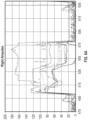
- Figure 8A shows an example contour plot 800 generated by using the data illustrated in Figure 7A .
- Such process may increase the signal amplitude and preserve the general shape attributes over the stance phase load cycle.
- Use of contour plot processing may minimize impacts of signals characteristics that are not coherent across all sensors in the array, and in facts may be used as a weak majority voting scheme at the same time. Characteristics that are common across all signals will get amplified.
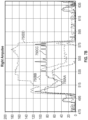
- a t max S 1 , t S 2 , t S 3 , t S 4 , t where A t is the maximum amplitude at time t and S x,t is sensor x signal amplitude at time t.
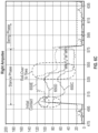
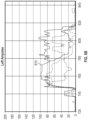
- Figure 8B illustrates an example plot 810 after applying the above maximum filter to the data presented in Figure 7A above.
- the plot 810 follows readings from the sensor 350AA (that is, a posterior-medial sensor) until mid-stance (after a few rapid transition during a heel strike) before switching to readings from the sensor 350CC (that is, an anterior-medial sensor) at the start of a rollover to the toes until loading is removed.
- firmware processing of the data streams such as heuristic rule-based decisions or weighted average.
- load line progression pattern of a specific user may be collected using the sensor assembly described above and be used to generate a user-specific methodology and/or signal processing algorithms/approaches.
- Such methodologies and/or signal processing algorithms/approaches may be used to detect different phases (for example, a stance phase and a swing phase) of the user's gait cycle.
- prosthetic devices may utilize a ground contact sensor assembly described above to accurately detect ground contacts for any user's gait cycle and, in turn, provide signals to operate its actuator to provide adequate stance phase control.
- Conditional language such as “may,” “could,” “might,” or “may,” unless specifically stated otherwise, or otherwise understood within the context as used, is generally intended to convey that certain embodiments include, while other embodiments do not include, certain features, elements, and/or steps. Thus, such conditional language is not generally intended to imply that features, elements, and/or steps are in any way required for one or more embodiments or that one or more embodiments necessarily include logic for deciding, with or without user input or prompting, whether these features, elements, and/or steps are included or are to be performed in any particular embodiment.
Landscapes
- Health & Medical Sciences (AREA)
- Transplantation (AREA)
- Heart & Thoracic Surgery (AREA)
- Oral & Maxillofacial Surgery (AREA)
- Engineering & Computer Science (AREA)
- Biomedical Technology (AREA)
- Cardiology (AREA)
- Vascular Medicine (AREA)
- Life Sciences & Earth Sciences (AREA)
- Animal Behavior & Ethology (AREA)
- General Health & Medical Sciences (AREA)
- Public Health (AREA)
- Veterinary Medicine (AREA)
- Orthopedic Medicine & Surgery (AREA)
- Prostheses (AREA)
Claims (15)
- Ein Bodenkontaktsensorsystem (500) für eine Unterschenkelprothese (100), das Folgendes (500) umfasst:ein erstes Element, das so konfiguriert ist, dass es an einem Schaft der Unterschenkelprothese (100) befestigt werden kann;ein zweites Element, das beweglich mit dem ersten Element verbunden ist und ein distales Verbindungsstück (108) aufweist, das zur Befestigung an einem Prothesenfuß oder - knöchel ausgelegt ist; undeine Vielzahl von Sensoren (350), die mit dem ersten oder zweiten Körper gekoppelt sind;dadurch gekennzeichnet, dass die Sensoren (350) dazu konfiguriert sind, Daten zu einer Vielzahl von Abständen zwischen dem ersten und dem zweiten Körper zu erzeugen.
- Bodenkontaktsensorsystem (500) nach Anspruch 1, wobei die Vielzahl von Sensoren (350) mit dem ersten Element verbunden sind.
- Bodenkontaktsensorsystem (500) nach Anspruch 1, wobei die Vielzahl von Sensoren (350) aus berührungslosen Abstandssensoren besteht, die mit dem ersten oder zweiten Element verbunden sind und dazu dienen, Daten in Bezug auf eine Vielzahl von Abständen zu jeweiligen Abschnitten des anderen Elements (erstes oder zweites Element) zu erzeugen.
- Bodenkontaktsensorsystem (500) nach einem der Ansprüche 1 oder 3, das ferner eine Vielzahl von Magneten (340) umfasst, die mit dem ersten oder zweiten Element verbunden sind, wobei die Vielzahl von Sensoren (350) aus einer Vielzahl von Hall-Effekt-Sensoren besteht, die mit dem jeweils anderen Element verbunden sind, und jeder Hall-Effekt-Sensor dazu konfiguriert ist, Daten in Bezug auf einen jeweiligen Abstand zu einem jeweiligen Magneten zu erzeugen.
- Bodenkontaktsensorsystem (500) nach einem der Ansprüche 1 bis 4, wobei die Daten in Bezug auf eine Vielzahl von Abständen erste Daten in Bezug auf eine Vielzahl von ersten Abständen und zweite Daten in Bezug auf eine Vielzahl von zweiten Abständen umfassen, wobei die ersten oder zweiten Daten als Reaktion auf eine nicht-träge Last erzeugt werden, die auf die Unterschenkelprothese (100) ausgeübt wird, und wobei die ersten und zweiten Daten anzeigen, dass mindestens einer der ersten Abstände sich von mindestens einem der zweiten Abstände unterscheidet.
- Bodenkontaktsensorsystem (500) nach einem der Ansprüche 1 bis 5, wobei die Vielzahl von Sensoren (350) in einer Querachsebene angeordnet sind.
- Bodenkontaktsensorsystem (500) nach einem der Ansprüche 1 bis 6, wobei das erste Element so konfiguriert ist, dass es sich in Bezug auf den Schaft nicht bewegt, während sich das zweite Element in Bezug auf das erste Element bewegt.
- Bodenkontaktsensorsystem (500) nach einem der Ansprüche 1 bis 7, wobei das erste Element eine teilweise anpassungsfähige Struktur aufweist, die Folgendes umfasst:ein erstes Paar von Balken (370), die sich an der medialen Seite des ersten Elements befinden und sich in anterior-posteriorer Richtung erstrecken, wobei die Balken (370) des ersten Paares in axialem Abstand zueinander stehen; undein zweites Paar von Balken (370), die sich an der lateralen Seite des ersten Elements befinden und sich in anterior-posteriorer Richtung erstrecken, wobei die Balken (370) des zweiten Paares in axialem Abstand zueinander stehen.
- Bodenkontaktsensorsystem (500) nach Anspruch 8, das ferner eine erste Brücke (372) umfasst, die das erste Balkenpaar (370) axial verbindet, und eine zweite Brücke, die das zweite Balkenpaar (370) axial verbindet.
- Bodenkontaktsensorsystem (500) nach einem der Ansprüche 1 bis 9, wobei die Daten in Bezug auf eine Vielzahl von Abständen zwischen dem ersten und zweiten Element als Reaktion auf eine Bodenkontaktlast erzeugt werden, die während der Standphase einer Schrittfolge auf das erste oder zweite Element ausgeübt wird.
- Bodenkontaktsensorsystem (500) nach einem der Ansprüche 1 bis 10, wobei die Vielzahl von Sensoren (350) dazu dient, Daten in Bezug auf eine vorbestimmte Vielzahl von axialen Abständen zwischen dem ersten und zweiten Element zu erzeugen, wenn keine Last auf den zweiten Körper ausgeübt wird.
- Bodenkontaktsensorsystem (500) nach einem der Ansprüche 1 bis 11, wobei zwischen dem ersten und dem zweiten Element mehrere Zwischenräume entstehen.
- Bodenkontaktsensorsystem (500) nach Anspruch 12, wobei sich die Größe der Zwischenräume entsprechend der Veränderungen in der Relativbewegung zwischen dem ersten und zweiten Element verändert.
- Verfahren zur Erkennung von Bodenkontakt durch eine Unterschenkelprothese (100), das Folgendes umfasst:Erfassen erster Daten in Bezug auf eine Vielzahl von ersten Abständen zwischen jedem Sensor einer Vielzahl von Sensoren (350) und einem sich bewegenden Elemente der Unterschenkelprothese (100);Erfassen zweiter Daten in Bezug auf eine Vielzahl von zweiten Abständen zwischen jedem Sensor der Vielzahl von Sensoren (350) und dem sich bewegenden Element der Unterschenkelprothese (100); undBestimmen, dass die Unterschenkelprothese (100) den Boden berührt hat, auf der Grundlage von ersten und zweiten Daten
- Verfahren nach Anspruch 14, das ferner Folgendes umfasst:Erfassen eines Magnetfelds, das von einer Vielzahl von Magneten (340) erzeugt wird, unter Verwendung jedes einzelnen der Sensoren (350);Bestimmen einer Stärke des Magnetfelds, das von jedem einzelnen der Sensoren (350) erfasst wird; undBerechnen der Vielzahl von zweiten Abständen, anhand der Stärke des Magnetfelds.
Applications Claiming Priority (2)
| Application Number | Priority Date | Filing Date | Title |
|---|---|---|---|
| US201962894442P | 2019-08-30 | 2019-08-30 | |
| PCT/US2020/045266 WO2021040998A1 (en) | 2019-08-30 | 2020-08-06 | Ground contact sensor array for lower-limb prosthetic and orthotic devices |
Publications (2)
| Publication Number | Publication Date |
|---|---|
| EP4021353A1 EP4021353A1 (de) | 2022-07-06 |
| EP4021353B1 true EP4021353B1 (de) | 2025-07-09 |
Family
ID=72193614
Family Applications (1)
| Application Number | Title | Priority Date | Filing Date |
|---|---|---|---|
| EP20761029.6A Active EP4021353B1 (de) | 2019-08-30 | 2020-08-06 | Bodenkontaktsensoranordnung für unterschenkelprothese und orthesen |
Country Status (3)
| Country | Link |
|---|---|
| US (1) | US20220401236A1 (de) |
| EP (1) | EP4021353B1 (de) |
| WO (1) | WO2021040998A1 (de) |
Families Citing this family (1)
| Publication number | Priority date | Publication date | Assignee | Title |
|---|---|---|---|---|
| EP4601589A1 (de) | 2022-10-10 | 2025-08-20 | Otto Bock Healthcare Products GmbH | Sensoreinrichtung |
Family Cites Families (8)
| Publication number | Priority date | Publication date | Assignee | Title |
|---|---|---|---|---|
| GB2302949B (en) * | 1995-07-01 | 1999-04-14 | Univ Salford | A transducer |
| DE10139333A1 (de) * | 2001-08-10 | 2003-03-06 | Biedermann Motech Gmbh | Sensoreinrichtung, insbesondere für eine Prothese und Prothese mit einer solchen Sensoreinrichtung |
| DE102005051495A1 (de) * | 2005-10-26 | 2007-05-03 | Otto Bock Healthcare Ip Gmbh & Co. Kg | Sensoranordnung für die Messung von Kräften und/oder Momenten und Verwendung der Sensoranordnung |
| EP2104475B1 (de) | 2007-01-05 | 2016-03-09 | Victhom Human Bionics Inc. | Gelenkbetätigungsmechanismus für eine prothesen- und/oder orthosenvorrichtung mit entsprechender übersetzung |
| EP2590598B1 (de) * | 2010-07-07 | 2019-03-13 | Össur HF | Bodenkontakterkennungssysteme und -verfahren für orthesen und prothesen für die unteren extremitäten |
| EP2621414B1 (de) * | 2010-09-29 | 2019-03-13 | Össur HF | Prothesen- und orthesenvorrichtung sowie verfahren und systeme zu ihrer steuerung |
| US9044346B2 (en) * | 2012-03-29 | 2015-06-02 | össur hf | Powered prosthetic hip joint |
| WO2015157723A1 (en) * | 2014-04-11 | 2015-10-15 | össur hf | Prosthetic foot with removable flexible members |
-
2020
- 2020-08-06 WO PCT/US2020/045266 patent/WO2021040998A1/en not_active Ceased
- 2020-08-06 US US17/638,493 patent/US20220401236A1/en active Pending
- 2020-08-06 EP EP20761029.6A patent/EP4021353B1/de active Active
Also Published As
| Publication number | Publication date |
|---|---|
| US20220401236A1 (en) | 2022-12-22 |
| EP4021353A1 (de) | 2022-07-06 |
| WO2021040998A1 (en) | 2021-03-04 |
Similar Documents
| Publication | Publication Date | Title |
|---|---|---|
| EP2809274B1 (de) | Parallelogrammwägezelle | |
| TWI563974B (zh) | 矯形感測器裝置 | |
| US7815689B2 (en) | Instrumented prosthetic foot | |
| KR101331091B1 (ko) | 보행 패턴 분석 방법 | |
| JP4320017B2 (ja) | 器械化義足 | |
| Park et al. | Flexible insole ground reaction force measurement shoes for jumping and running | |
| US8555715B2 (en) | Ground contact sensing systems and methods for lower-limb orthotic and prosthetic devices | |
| KR101648270B1 (ko) | 보행 단계 판정을 위한 발모듈, 이를 이용한 보행 단계 판정 방법, 보행 분석 시스템 및 능동형 보행 보조 장치 | |
| Chandel et al. | Pi-sole: A low-cost solution for gait monitoring using off-the-shelf piezoelectric sensors and imu | |
| EP4021353B1 (de) | Bodenkontaktsensoranordnung für unterschenkelprothese und orthesen | |
| KR101572183B1 (ko) | 압력 분석을 통한 내·외 족지 보행 분석방법 | |
| Yu et al. | A walking monitoring shoe system for simultaneous plantar-force measurement and gait-phase detection | |
| Lind et al. | Multi-axis foot reaction force/torque sensor for biomedical applications | |
| Billing et al. | Predicting ground reaction forces in running using micro-sensors and neural networks | |
| Kalamdani et al. | Robots with sensitive feet | |
| KR102251104B1 (ko) | 착용형 보행 분석 장치 | |
| CN107423658B (zh) | 步态识别方法及装置 | |
| Latsch et al. | A Review of Sensor Insoles | |
| Huang et al. | A Facile Low-Cost Wireless Self-Powered Footwear System for Monitoring Plantar Pressure | |
| KR102473667B1 (ko) | 보행단계분석 및 예측제어가 가능한 인공지능 기반 스마트 의족 시스템 | |
| US20240172993A1 (en) | Sensors for prostheses | |
| Roetenberg et al. | Camera-marker and inertial sensor fusion for improved motion tracking | |
| Orhan et al. | Assessing Balance During Gait | |
| Li et al. | A Review of Wearable Inertial Sensor Gait Modeling | |
| Gupta et al. | Biomechanics of Gait |
Legal Events
| Date | Code | Title | Description |
|---|---|---|---|
| STAA | Information on the status of an ep patent application or granted ep patent |
Free format text: STATUS: UNKNOWN |
|
| STAA | Information on the status of an ep patent application or granted ep patent |
Free format text: STATUS: THE INTERNATIONAL PUBLICATION HAS BEEN MADE |
|
| PUAI | Public reference made under article 153(3) epc to a published international application that has entered the european phase |
Free format text: ORIGINAL CODE: 0009012 |
|
| STAA | Information on the status of an ep patent application or granted ep patent |
Free format text: STATUS: REQUEST FOR EXAMINATION WAS MADE |
|
| 17P | Request for examination filed |
Effective date: 20220325 |
|
| AK | Designated contracting states |
Kind code of ref document: A1 Designated state(s): AL AT BE BG CH CY CZ DE DK EE ES FI FR GB GR HR HU IE IS IT LI LT LU LV MC MK MT NL NO PL PT RO RS SE SI SK SM TR |
|
| DAV | Request for validation of the european patent (deleted) | ||
| DAX | Request for extension of the european patent (deleted) | ||
| GRAP | Despatch of communication of intention to grant a patent |
Free format text: ORIGINAL CODE: EPIDOSNIGR1 |
|
| STAA | Information on the status of an ep patent application or granted ep patent |
Free format text: STATUS: GRANT OF PATENT IS INTENDED |
|
| INTG | Intention to grant announced |
Effective date: 20250224 |
|
| GRAS | Grant fee paid |
Free format text: ORIGINAL CODE: EPIDOSNIGR3 |
|
| GRAA | (expected) grant |
Free format text: ORIGINAL CODE: 0009210 |
|
| STAA | Information on the status of an ep patent application or granted ep patent |
Free format text: STATUS: THE PATENT HAS BEEN GRANTED |
|
| P01 | Opt-out of the competence of the unified patent court (upc) registered |
Free format text: CASE NUMBER: APP_23981/2025 Effective date: 20250520 |
|
| AK | Designated contracting states |
Kind code of ref document: B1 Designated state(s): AL AT BE BG CH CY CZ DE DK EE ES FI FR GB GR HR HU IE IS IT LI LT LU LV MC MK MT NL NO PL PT RO RS SE SI SK SM TR |
|
| REG | Reference to a national code |
Ref country code: GB Ref legal event code: FG4D |
|
| REG | Reference to a national code |
Ref country code: CH Ref legal event code: EP |
|
| REG | Reference to a national code |
Ref country code: IE Ref legal event code: FG4D |
|
| REG | Reference to a national code |
Ref country code: DE Ref legal event code: R096 Ref document number: 602020054216 Country of ref document: DE |
|
| PGFP | Annual fee paid to national office [announced via postgrant information from national office to epo] |
Ref country code: FR Payment date: 20250818 Year of fee payment: 6 |
|
| REG | Reference to a national code |
Ref country code: NL Ref legal event code: MP Effective date: 20250709 |
|
| PG25 | Lapsed in a contracting state [announced via postgrant information from national office to epo] |
Ref country code: PT Free format text: LAPSE BECAUSE OF FAILURE TO SUBMIT A TRANSLATION OF THE DESCRIPTION OR TO PAY THE FEE WITHIN THE PRESCRIBED TIME-LIMIT Effective date: 20251110 |
|
| PG25 | Lapsed in a contracting state [announced via postgrant information from national office to epo] |
Ref country code: NL Free format text: LAPSE BECAUSE OF FAILURE TO SUBMIT A TRANSLATION OF THE DESCRIPTION OR TO PAY THE FEE WITHIN THE PRESCRIBED TIME-LIMIT Effective date: 20250709 |
|
| REG | Reference to a national code |
Ref country code: AT Ref legal event code: MK05 Ref document number: 1811126 Country of ref document: AT Kind code of ref document: T Effective date: 20250709 |