EP4021072A1 - Procédé, appareil et système de traitement de données - Google Patents
Procédé, appareil et système de traitement de données Download PDFInfo
- Publication number
- EP4021072A1 EP4021072A1 EP20858600.8A EP20858600A EP4021072A1 EP 4021072 A1 EP4021072 A1 EP 4021072A1 EP 20858600 A EP20858600 A EP 20858600A EP 4021072 A1 EP4021072 A1 EP 4021072A1
- Authority
- EP
- European Patent Office
- Prior art keywords
- access network
- end marker
- data flow
- network device
- marker message
- Prior art date
- Legal status (The legal status is an assumption and is not a legal conclusion. Google has not performed a legal analysis and makes no representation as to the accuracy of the status listed.)
- Pending
Links
- 238000003672 processing method Methods 0.000 title claims description 19
- 239000003550 marker Substances 0.000 claims abstract description 327
- 238000000034 method Methods 0.000 claims abstract description 94
- 230000006870 function Effects 0.000 claims description 111
- 230000006854 communication Effects 0.000 claims description 42
- 238000004891 communication Methods 0.000 claims description 41
- 238000004590 computer program Methods 0.000 claims description 6
- 238000012545 processing Methods 0.000 abstract description 41
- 238000013461 design Methods 0.000 description 25
- 238000010586 diagram Methods 0.000 description 19
- 238000007726 management method Methods 0.000 description 19
- 230000008569 process Effects 0.000 description 19
- 230000005540 biological transmission Effects 0.000 description 18
- 230000004048 modification Effects 0.000 description 15
- 238000012986 modification Methods 0.000 description 15
- 230000011664 signaling Effects 0.000 description 10
- 230000004044 response Effects 0.000 description 8
- 230000003287 optical effect Effects 0.000 description 4
- 238000005516 engineering process Methods 0.000 description 3
- 238000013523 data management Methods 0.000 description 2
- 230000003068 static effect Effects 0.000 description 2
- 230000005641 tunneling Effects 0.000 description 2
- JZEPSDIWGBJOEH-UHFFFAOYSA-N 4-decylbicyclo[2.2.1]hept-2-ene Chemical compound C1CC2C=CC1(CCCCCCCCCC)C2 JZEPSDIWGBJOEH-UHFFFAOYSA-N 0.000 description 1
- 101150119040 Nsmf gene Proteins 0.000 description 1
- 230000003190 augmentative effect Effects 0.000 description 1
- 230000006399 behavior Effects 0.000 description 1
- 230000009286 beneficial effect Effects 0.000 description 1
- 230000008859 change Effects 0.000 description 1
- 238000013500 data storage Methods 0.000 description 1
- 230000001419 dependent effect Effects 0.000 description 1
- 230000004069 differentiation Effects 0.000 description 1
- 230000000694 effects Effects 0.000 description 1
- 239000000835 fiber Substances 0.000 description 1
- 238000013507 mapping Methods 0.000 description 1
- 239000013307 optical fiber Substances 0.000 description 1
- 239000004065 semiconductor Substances 0.000 description 1
- 239000007787 solid Substances 0.000 description 1
- XLYOFNOQVPJJNP-UHFFFAOYSA-N water Substances O XLYOFNOQVPJJNP-UHFFFAOYSA-N 0.000 description 1
Images


Classifications
-
- H—ELECTRICITY
- H04—ELECTRIC COMMUNICATION TECHNIQUE
- H04W—WIRELESS COMMUNICATION NETWORKS
- H04W28/00—Network traffic management; Network resource management
- H04W28/02—Traffic management, e.g. flow control or congestion control
- H04W28/0268—Traffic management, e.g. flow control or congestion control using specific QoS parameters for wireless networks, e.g. QoS class identifier [QCI] or guaranteed bit rate [GBR]
-
- H—ELECTRICITY
- H04—ELECTRIC COMMUNICATION TECHNIQUE
- H04W—WIRELESS COMMUNICATION NETWORKS
- H04W36/00—Hand-off or reselection arrangements
- H04W36/02—Buffering or recovering information during reselection ; Modification of the traffic flow during hand-off
- H04W36/023—Buffering or recovering information during reselection
-
- H—ELECTRICITY
- H04—ELECTRIC COMMUNICATION TECHNIQUE
- H04W—WIRELESS COMMUNICATION NETWORKS
- H04W36/00—Hand-off or reselection arrangements
- H04W36/0005—Control or signalling for completing the hand-off
- H04W36/0055—Transmission or use of information for re-establishing the radio link
- H04W36/0069—Transmission or use of information for re-establishing the radio link in case of dual connectivity, e.g. decoupled uplink/downlink
-
- H—ELECTRICITY
- H04—ELECTRIC COMMUNICATION TECHNIQUE
- H04W—WIRELESS COMMUNICATION NETWORKS
- H04W36/00—Hand-off or reselection arrangements
- H04W36/12—Reselecting a serving backbone network switching or routing node
-
- H—ELECTRICITY
- H04—ELECTRIC COMMUNICATION TECHNIQUE
- H04W—WIRELESS COMMUNICATION NETWORKS
- H04W76/00—Connection management
- H04W76/10—Connection setup
- H04W76/11—Allocation or use of connection identifiers
-
- H—ELECTRICITY
- H04—ELECTRIC COMMUNICATION TECHNIQUE
- H04W—WIRELESS COMMUNICATION NETWORKS
- H04W76/00—Connection management
- H04W76/10—Connection setup
- H04W76/15—Setup of multiple wireless link connections
-
- H—ELECTRICITY
- H04—ELECTRIC COMMUNICATION TECHNIQUE
- H04W—WIRELESS COMMUNICATION NETWORKS
- H04W76/00—Connection management
- H04W76/20—Manipulation of established connections
- H04W76/22—Manipulation of transport tunnels
-
- H—ELECTRICITY
- H04—ELECTRIC COMMUNICATION TECHNIQUE
- H04W—WIRELESS COMMUNICATION NETWORKS
- H04W88/00—Devices specially adapted for wireless communication networks, e.g. terminals, base stations or access point devices
- H04W88/02—Terminal devices
- H04W88/06—Terminal devices adapted for operation in multiple networks or having at least two operational modes, e.g. multi-mode terminals
Definitions
- This application relates to wireless communications technologies, and in particular, to a data processing method, an apparatus, and a system.
- a bandwidth resource and a coverage area of a single access network device are limited.
- a multi-connection mode for providing a service for a terminal device by using radio resources of a plurality of access network devices can increase a data throughput of the terminal device, improve communication performance of the terminal device, and increase radio resource utilization.
- a part of data flows in a session established by the terminal device through a first access network device may be switched from the first access network device to a second access network device, and the terminal may receive different data flows of a same session from the first access network device and the second access network device.
- transmission of the data flows may be interrupted.
- Embodiments of this application provide a data processing method, an apparatus, and a system, to avoid a service interruption in a data flow switch procedure.
- a data processing method includes:
- a first access network device receives an end marker message from a core network element, where the end marker message includes indication information, the indication information is used to indicate a first data flow on which the end marker message works in a first session, and the first data flow is a data flow switched from the first access network device to a second access network device;
- the first access network device can distinguish, based on the indication information included in the end marker message, a data flow on which the end marker message works, and after receiving the end marker message, the first access network device continues to send a data packet of the second data flow kept on the first access network device to the terminal device without discarding the data packet of the second data flow. This avoids a transmission interruption of the second data flow, and ensures service continuity.
- the first access network device discards the first data packet if the first access network device receives a first data packet of the first data flow after receiving the end marker message.
- the method includes:
- a first access network device receives an end marker message from a core network element, where the end marker message includes indication information, the indication information is used to indicate a data flow on which the end marker message works, and the data flow on which the end marker message works is a first data flow switched from the first access network device to a second access network device in a first session; and the first access network device determines, based on the indication information, that the end marker message works on the first data flow, so that the first access network device does not discard a data packet of a second data flow that is in the first session and that is kept on the first access network device.
- the data flow on which the end marker message works may alternatively be expressed as a data flow corresponding to the end marker message or a data flow associated with the end marker message. It may be understood that the end marker message affects the data flow on which the end marker message works, that corresponds to the end marker message, or that is associated with the end marker message.
- the method further includes: the first access network device forwards a data packet of the first data flow to the second access network device; and when the first access network device completes forwarding, to the second access network device, a data packet that is of the first data flow and that is received by the first access network device before the end marker message, the first access network device sends a second end marker message to the second access network device.
- the second end marker message may be the foregoing end marker message received by the first access network device.
- the second end marker message may be generated by the second access network device, and the second end marker message may include or not include the foregoing indication information.
- the indication information may include an identifier of a data flow on which the end marker message works.
- the indication information includes an identifier of the first data flow.
- identifiers of the plurality of data flows may be included.
- the indication information may include an identifier of a data flow on which the end marker message does not works.
- the indication information includes an identifier of the second data flow. The data flow on which the end marker message works may be learned based on the identifier of the data flow on which the end marker message does not works.
- the indication information includes a bit sequence.
- a plurality of bits in the bit sequence one-to-one correspond to a plurality of data flows in the first session.
- a value of the bit is a first value or a second value, the first value indicates that the end marker message works on a data flow, and the second value is used to indicate that the end marker message does not works on a data flow.
- a value of a bit corresponding to the first data flow is the first value
- a value of a bit corresponding to the second data flow is the second value.
- the indication information in the indication information, a correspondence is established between a plurality of bits in one field and a plurality of data flows. Compared with the foregoing implementation in which the identifier of the data flow on which the end marker message works is included in the end marker message, this manner reduces storage and transmission resources occupied by the indication information.
- that the end marker message includes the indication information includes: A protocol header of the end marker message includes the indication information; or a content information element of the end marker message includes the indication information.
- the first access network device is a master base station, and the second access network device is a secondary base station; or the first access network device is a secondary base station, and the second access network device is a master base station.
- the core network element is a user plane function network element.
- the core network element is a session management function network element.
- a data processing method includes: a core network element obtains an end marker message, where the end marker message includes indication information, the indication information is used to indicate a first data flow on which the end marker message works in a first session, and the first data flow is a data flow switched from a first access network device to a second access network device; and the core network element sends the end marker message to the first access network device.
- the core network element sends the end marker message to the first access network device, so that the first access network device can distinguish, based on the indication information included in the end marker message, a data flow on which the end marker works, and after receiving the end marker message, the first access network device continues to send a data packet of a second data flow kept on the first access network device to a terminal device without discarding the data packet of the second data flow. This avoids a transmission interruption of the second data flow, and ensures service continuity.
- the data flow on which the end marker message works may alternatively be expressed as a data flow corresponding to the end marker message or a data flow associated with the end marker message. It may be understood that the end marker message affects the data flow on which the end marker message works, that corresponds to the end marker message, or that is associated with the end marker message.
- that the core network element obtains the end marker message includes: The core network element generates the end marker message; or the core network element receives the end marker message from a control network element.
- the core network element may be a user plane function network element, and the control network element may be a session management function network element.
- the method further includes: After sending the end marker message, the core network element continues to send a second data packet of the second data flow in the first session to the first access network device, where the second data flow is a data flow kept on the first access network device.
- the indication information may include an identifier of a data flow on which the end marker message works.
- the indication information includes an identifier of the first data flow.
- identifiers of the plurality of data flows may be included.
- the indication information may include an identifier of a data flow on which the end marker message does not works.
- the indication information includes an identifier of the second data flow. The data flow on which the end marker message works may be learned based on the identifier of the data flow on which the end marker message does not works.
- the indication information includes a bit sequence.
- a plurality of bits in the bit sequence one-to-one correspond to a plurality of data flows in the first session.
- a value of the bit is a first value or a second value, the first value indicates that the end marker message works on a data flow, and the second value is used to indicate that the end marker message does not works on a data flow.
- a value of a bit corresponding to the first data flow is the first value
- a value of a bit corresponding to the second data flow is the second value.
- the indication information in the indication information, a correspondence is established between a plurality of bits in one field and a plurality of data flows. Compared with the foregoing implementation in which the identifier of the data flow on which the end marker message works is included in the end marker message, this manner reduces storage and transmission resources occupied by the indication information.
- that the end marker message includes the indication information includes: A protocol header of the end marker message includes the indication information; or a content information element of the end marker message includes the indication information.
- the first access network device is a master base station, and the second access network device is a secondary base station; or the first access network device is a secondary base station, and the second access network device is a master base station.
- a data processing method includes:
- the method includes:
- the first access network device can correctly distinguish, based on the learned data flow that is switched from the first access network device, the data flow on which the end marker message works, and after receiving the end marker message, the first access network device continues to send a data packet of the second data flow kept on the first access network device to the terminal device without discarding the data packet of the second data flow. This avoids a transmission interruption of the second data flow, and ensures service continuity.
- the first access network device may learn, in a data flow switch procedure, the data flow switched from the first access network device, and a specific learning manner is not limited.
- the first access network device discards the first data packet if the first access network device receives a first data packet of the first data flow after receiving the end marker message.
- the data flow on which the end marker message works may alternatively be expressed as a data flow corresponding to the end marker message or a data flow associated with the end marker message. It may be understood that the end marker message affects the data flow on which the end marker message works, that corresponds to the end marker message, or that is associated with the end marker message.
- the end marker message includes second indication information, and the second indication information is used to indicate that the end marker message works on a part of data flows in the first session.
- the first access network device may learn, based on the second indication information, that the end marker message is not used for all data flows of the first session. Therefore, the first access network device may determine, based on the second indication information, that the end marker message works on the first data flow.
- the end marker message includes second indication information, and the second indication information is used to indicate a data flow switch scenario.
- the data flow switch scenario means that the end marker message works on a part of data flows in the first session instead of all data flows in the first session. Therefore, the first access network device may use, based on the second indication information, the data flow switched from the first access network device as the data flow on which the end marker message works.
- the first access network device is a master base station, and a second access network device is a secondary base station; or the first access network device is a secondary base station, and a second access network device is a master base station.
- the first core network element is a session management function network element
- the second core network element is a user plane function network element
- the first core network element is an access and mobility management function network element
- the second core network element is a user plane function network element
- an access network apparatus is provided, and is configured to implement the method in the first aspect.
- the access network apparatus may be the first access network device in the first aspect, or an apparatus including the first access network device.
- the access network apparatus includes a corresponding module, unit, or means (means) for implementing the foregoing method.
- the module, unit, or means may be implemented by hardware, implemented by software, or implemented by hardware executing corresponding software.
- the hardware or the software includes one or more modules or units corresponding to the foregoing functions.
- a core network apparatus is provided, and is configured to implement the method in the second aspect.
- the core network apparatus may be the core network element in the second aspect, or an apparatus including the core network element.
- the core network apparatus includes a corresponding module, unit, or means (means) for implementing the foregoing method.
- the module, unit, or means may be implemented by hardware, implemented by software, or implemented by hardware executing corresponding software.
- the hardware or the software includes one or more modules or units corresponding to the foregoing functions.
- an access network apparatus is provided, and is configured to implement the method in the third aspect.
- the access network apparatus may be the first access network device in the third aspect, or an apparatus including the first access network device.
- the access network apparatus includes a corresponding module, unit, or means (means) for implementing the foregoing method.
- the module, unit, or means may be implemented by hardware, implemented by software, or implemented by hardware executing corresponding software.
- the hardware or the software includes one or more modules or units corresponding to the foregoing functions.
- an access network apparatus includes: a processor, where the processor is configured to read and run instructions in a memory, to implement the method provided in the first aspect.
- the access network apparatus may include the memory.
- the access network apparatus may be a base station or a chip.
- a core network apparatus includes: a processor, where the processor is configured to read and run instructions in a memory, to implement the method provided in the second aspect.
- the core network apparatus may include the memory.
- the core network apparatus may be a core network element or a chip.
- an access network apparatus includes: a processor, where the processor is configured to read and run instructions in a memory, to implement the method provided in the third aspect.
- the access network apparatus may include the memory.
- the access network apparatus may be a base station or a chip.
- a computer storage medium where the computer storage medium includes instructions.
- the apparatus is enabled to implement any one of the foregoing methods.
- an embodiment of this application provides a computer program product, including instructions.
- the instructions When the instructions are run on the foregoing access network apparatus or the foregoing core network apparatus, the apparatus is enabled to implement any one of the foregoing methods.
- a communications system includes the access network apparatus according to the fourth aspect or the seventh aspect and the core network apparatus according to the fifth aspect or the eighth aspect.
- a communications system includes the access network apparatus according to the sixth aspect or the ninth aspect.
- the communications system may further include a user plane function network element.
- the communications system may further include an access and mobility management function network element or a session management function network element.
- Table 1 lists English abbreviations and English full names in this application.
- Table 1 English abbreviation English full name 5GC 5G core network RAN radio access network AMF access and mobility management function SMF session management function UPF user plane function PCF policy control function AUSF authentication server function UDM unified data management NSSF network slice selection function AF application function DN data network UE user equipment SM session management IP internet protocol QoS quality of service QoS flow quality of service flow PDU packet data unit PDU session packet data unit session QFI quality of service flow identifier DC dual-connectivity end marker PDU Session ID packet data unit identifier AN Tunnel Info access node tunnel information NG-U next generation user plane interface NG-RAN next generation radio access network NG-U Tunnel next generation user plane interface tunnel GTP-U GPRS Tunneling Protocol-User Plane G-PDU GPRS Tunneling protocol-packet data unit T-PDU tunneled packet data unit Radio RB Radio Bearer gNB gNodeB eNB evolved No
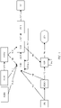
- FIG. 1 is a schematic diagram of an architecture of a 5G communications system.
- the communications system includes a core network part and an access network part.
- An access network may also be referred to as a radio access network RAN.
- a core network may include an AMF network element, an SMF network element, a UPF network element, a PCF network element, an AUSF network element, a UDM network element, and an NSSF network element.
- An AF network element may be connected to the PCF, to provide an application service.
- the UPF may be connected to a DN.
- UE may access the DN through the communications system.
- the AMF network element is a network element used for access and mobility management.
- the network element is mainly used for access control, mobility management, attach and detach, and SMF network element selection.
- the network element may serve as an anchor of a signaling connection between N1 and N2, to provide a route of an N1/N2 SM message for the SMF.
- the SMF network element is a network element used for session management.
- the network element is mainly used for providing control-plane functions for session management, such as session creation, modification, and release.
- the network element may assign an IP address to a UE and select and redirect a UPF network element.
- the UPF network element is a network element used for user plane processing.
- the network element is mainly used for processing a user plane service, for example, data packet routing and forwarding, and QoS mapping and execution.
- the network element may receive user data from the DN, and transmit the user data to the UE through an access network device.
- the network element may further receive user data from the UE through the access network device, and forward the user data to the DN.
- the SMF network element manages and controls a transmission resource and a scheduling function of the network element that are used for providing a service for the UE.
- the PCF network element is a network element used for policy control.
- the network element is mainly used for providing a unified policy framework to manage network behaviors and providing a policy rule for a control layer network function, and is responsible for obtaining policy-related subscription information of a subscriber.
- the AUSF network element is a network element used for authentication.
- the network element works on access authentication.
- the UDM network element is a network element used for data management.
- the network element is mainly used for generating an authentication parameter, storing and managing an ID of a permanent user in a system, and performing registration management on network elements serving the user, for example, an AMF and an SMF that currently provide a service for a terminal device.
- the NSSF network element is a network element used for selecting a network slice.
- the network element is mainly used for determining a network slice instance that is allowed to be accessed by the UE.
- the access network device is a device that provides a wireless communication function for the terminal device.
- the access network device includes but is not limited to an evolved NodeB (evolved NodeB, eNB), a radio network controller (radio network controller, RNC), a NodeB (NodeB, NB), a donor eNodeB (donor evolved NodeB, DeNB), a base station controller (base station controller, BSC), a base transceiver station (base transceiver station, BTS), a home NodeB (for example, a home evolved NodeB or a home NodeB, HNB), a baseband unit (baseband unit, BBU), an access point (access point, AP), a wireless relay node, a wireless backhaul node, a transmission point (transmission point, TP), or a transmission and reception point (transmission and reception point, TRP) in a wireless fidelity (wireless fidelity, Wi-Fi) system, or the like.
- RNC radio network controller
- the access network device may alternatively be a next generation NB (generation, gNB) or a transmission point (for example, a TRP or a TP) in a 5G system, for example, a new radio (new radio, NR) system, or one antenna panel or a group of antenna panels (including a plurality of antenna panels) of a base station in a 5G system, or may be a network node, for example, a BBU or a distributed unit (distributed unit, DU), that constitutes a gNB or a transmission point.
- the gNB may include a centralized unit (centralized unit, CU) and a DU.
- the gNB may further include a radio unit (radio unit, RU).
- the CU implements a part of functions of the gNB
- the DU implements a part of functions of the gNB.
- the CU implements functions of an RRC layer and a PDCP layer
- the DU implements functions of an RLC layer, a MAC layer, and a PHY layer.
- Information at the RRC layer eventually becomes information at the PHY layer, or is converted from information at the PHY layer.
- higher layer signaling for example, RRC layer signaling or PDCP layer signaling
- the access network device may be a CU node, a DU node, or a device including a CU node and a DU node.
- the CU may be classified as a network device in an access network, or the CU may be classified as a network device in a core network (core network, CN). This is not limited herein.
- the AF network element is a network element used for an application service.
- the network element is mainly used for interacting with a 3GPP core network to provide a service, for example, to affect a data routing decision, interact with a policy control function, or provide some services of a third party to a network side.
- the DN is a data network.
- the DN is mainly used for providing services for users, such as an operator's service, an internet access service, and a third-party service.
- the terminal device is a device having a wireless transceiving function, and is referred to as UE in the embodiments of this application.
- the terminal device may be deployed on land, including an indoor device, an outdoor device, a handheld device, or a vehicle-mounted device, or may be deployed on a water surface (for example, on a ship), or may be deployed in the air (for example, on an aircraft, a balloon, or a satellite).
- the terminal device may be a mobile phone, a tablet computer, a computer having a wireless transceiving function, a VR terminal, an AR terminal, a wireless terminal in industrial control, a wireless terminal in self-driving, a wireless terminal in telemedicine, a wireless terminal in a smart grid, a wireless terminal in transportation security, a wireless terminal in a smart city, a wireless terminal in a smart home, or the like.
- the access network device is connected to the UPF through a user plane interface N3, and is configured to transmit data of the UE.
- the access network device establishes a control plane signaling connection to the AMF through a control plane interface N2.
- the AMF establishes a signaling connection to the UE through an N1 interface.
- the AMF is connected to the SMF through an N11 interface.
- the AMF serves as an anchor of a signaling connection between N1 and N2, to provide a route of an N1 or N2 SM message for the SMF.
- the UPF is connected to the SMF through an N4 interface.
- a session in the embodiments of this application may be a PDU session in a 5G network.
- a data flow in the embodiments of this application may be a QoS flow in the 5G network.
- one UE may simultaneously create a plurality of PDU sessions to access a same DN or different DNs, and access one DN by using each PDU session.
- Establishment of one PDU session means establishment of one data transmission channel between the UE and the DN.
- a minimum QoS differentiation granularity in a PDU session is a QoS flow.
- One PDU session may include a plurality of QoS flows.
- One QFI identifies one QoS flow, and the identifier is unique in each PDU session.
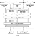
- a QoS flow is transmitted on a per data packet basis. Packets in a same QoS flow have a same QoS guarantee (such as a packet delay, a packet error rate, and a priority). Different QoS guarantees need to be provided by different QoS flows. As shown in FIG. 2 , one QoS flow can be mapped to one radio bearer, and one radio bearer can carry one or more QoS flows. In a single connection scenario in which UE establishes a PDU session through one access network device, one PDU session uses one N3 tunnel, and a plurality of QoS flows in the PDU session share the N3 tunnel.
- the N3 tunnel may be an NG-U tunnel. The tunnel uses a GTP-U protocol.
- the protocol is used to provide a data packet transmission and reception service for a user plane entity.
- the tunnel can be used to transmit a G-PDU message that includes a GTP-U protocol header and a T-PDU, or transmit a GTP-U signaling message that includes a GTP-U protocol header and an information element.
- the T-PDU includes a user data packet, and the data packet may be an IP datagram.
- One UE may receive signals of a plurality of access network devices having different frequency bands and strengths.
- One UE can simultaneously send or receive data to or from a plurality of access network devices. This is referred to as multi-connectivity.
- One UE simultaneously establishes connections to two access network devices, and sends or receives data through the two connections. This may be referred to as dual-connectivity.
- a person skilled in the art should learn that a technical solution applicable to a dual-connectivity scenario is also applicable to a multi-connectivity scenario.
- a part of QoS flows in a PDU session of the UE may be switched from a first access network device to a second access network device, and a part of QoS flows in the session are kept on the first access network device, so that the QoS flows of the PDU session can be offloaded to the two access network devices.
- the first access network device may be a master access network device
- the second access network device may be a secondary access network device.
- the first access network device may be a secondary access network device
- the second access network device may be a master access network device.
- an example in which the first access network device is a master access network device and the second access network device is a secondary access network device works on description.
- the master access network device is represented by an M-RAN node
- the secondary access network device is represented by an S-RAN node.
- this application provides a plurality of embodiments to describe in detail the technical solutions of this application.
- Embodiment 1 describes a QoS flow switch procedure in a dual-connectivity scenario.
- UE may switch, from an M-RAN node to an S-RAN node according to the QoS flow switch procedure, a part of QoS flows in a PDU session carried on the M-RAN node.
- an SMF or a UPF generates an end marker message to be sent to the M-RAN node.
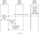
- FIG. 3A and FIG. 3B the following steps are included.
- the S-RAN node sends a data forwarding address to the M-RAN node.
- the M-RAN may forward data to the S-RAN based on the forwarding address.
- the M-RAN node may forward, to the S-RAN node, a data packet that is buffered on the M-RAN node and that is of a QoS flow switched from the M-RAN node to the S-RAN node in the PDU session.
- the M-RAN node may send a data packet of a QoS flow kept on the M-RAN to the UE.
- the M-RAN node may be considered as a source node, and the S-RAN node may be considered as a target node.
- N2 quality of service flow mobility indication N2 QoS Flow mobility Indication
- the S102 part may be as follows:
- the M-RAN node may send PDU session resource modify indication (PDU SESSION RESOURCE MODIFY INDICATION) information to the AMF
- the foregoing two types of indication information may include a PDU Session ID, QFI(s), and AN Tunnel Info.
- the PDU Session ID is used to indicate a PDU session in which a to-be-switched QoS flow is located.
- the QFI(s) is used to indicate the to-be-switched QoS flow.
- the AN Tunnel Info is used to indicate a downlink tunnel endpoint of the S-RAN node.
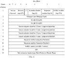
- UE A establishes two PDU sessions in a 5G communications system: PSession #1 and PSession #2.
- PSession #1 includes two QoS flows: Qflow #1-1 and Qflow #1-2.
- PSession #2 includes four QoS flows: Qflow #2-1, Qflow #2-2, Qflow #2-3, and Qflow #2-4. IDs of the PDU sessions and the QoS flows are shown in Table 2.
- the AN Tunnel Info of the S-RAN node is TInfo#02.
- the PDU Session ID is 010
- the QFIs are 00000001 and 00000010
- the AN Tunnel Info is TInfo#02.
- Embodiment 1 For ease of description, the following steps in Embodiment 1 are illustrated based on the foregoing example.
- the AMF sends a PDU session update management context request (Nsmf_PDUSession_UpdateSMContext request) to the SMF.
- the request includes the PDU Session ID, the QFI(s), and the AN Tunnel Info.
- the SMF sends an N4 session modification request (N4 Session Modification Request) to the UPF.
- N4 Session Modification Request N4 Session Modification Request
- the request includes the QFI(s), the AN Tunnel Info, and an identifier that is used to indicate PDU session information.
- the identifier may be an N4 interface session endpoint identifier (Session Endpoint Identifier), an N4 interface session identifier (N4 Session ID), or the PDU Session ID.
- An N4 interface is an interface between the SMF and the UPF.
- the UPF switches the to-be-switched QoS flow to the S-RAN node.
- N4 Session Modification Response N4 Session Modification Response
- the SMF sends a PDU session update management context response (Nsmf PDUSession UpdateSMContext response) to the AMF
- the UPF may send the data packet of the switched QoS flow to the S-RAN node.
- the UPF may send the data packet of the QoS flow kept on the M-RAN node to the M-RAN node.
- S107 The SMF sends a first end marker message to the UPF.
- the SMF learns that the to-be-switched QoS flow has been switched to the S-RAN, and the SMF may send the first end marker message to the UPF.
- the first end marker message is generated by the SMF.
- the first end marker message includes indication information.
- the indication information is used to indicate a QoS flow corresponding to the first end marker message (that is, a QoS flow on which the end marker message works), where the QoS flow is the QoS flow switched from the M-RAN to the S-RAN in the dual-connectivity scenario.
- the first end marker message may correspond to one or more QoS flows switched from the M-RAN to the S-RAN.
- a data flow corresponding to the end marker message and a data flow on which the end marker message works indicate a same meaning, and both mean that the data flow is affected by the end marker message.
- the first end marker message may alternatively be generated by the UPF.
- S107 may be expressed as: The UPF generates the first end marker message.
- carrying the indication information in the end marker message may be considered as that the end marker message works on the QoS flow indicated by the indication information, but is not used for another QoS flow in the PDU session.
- the QoS flow indicated by the indication information may be a switched QoS flow.
- the M-RAN node learns, based on the indication information in the first end marker message, that QoS flows on which the first end marker message works in the PDU session are switched QoS flows, for example, Qflow#2-1 and Qflow#2-2, and another QoS flow in the PDU session is a QoS flow kept on the M-RAN node, which is referred to as a kept QoS flow.
- the M-RAN node may receive the data packet of the switched QoS flow or the data packet of the kept QoS flow. Because the M-RAN node learns the QoS flow on which the first end marker message works, the M-RAN node may perform different processing on data packets of different QoS flows, as shown in S108a and S108b (which are not shown in FIG. 3A and FIG. 3B ).
- S108a The M-RAN node discards the data packet that is of the switched QoS flow and that is received after the first end marker message.
- the M-RAN node may discard the data packet that is received after the first end marker message and that is of the switched QoS flow on which the first end marker message works.
- S108b The M-RAN node continues to send the data packet of the kept data flow to a terminal device.
- the M-RAN node After learning the QoS flow on which the first end marker message works, the M-RAN node can correctly distinguish a QoS flow for which the first end marker message is not used.
- the M-RAN node may not discard a data packet that is received after the first end marker message and that is of the QoS flow for which the first end marker message is not used. In other words, the M-RAN node may continue to send, to the UE, the data packet that is received after the first end marker message and that is of the QoS flow for which the first end marker message is not used.
- a data flow switched from the first access network device to the second access network device is briefly referred to as a data flow that has been switched or a switched data flow
- a data flow kept on the first access network device that is, a data flow that is not switched from the first access network device to the second access network device
- a data flow that is not switched or a kept data flow is briefly referred to as a data flow that is not switched or a kept data flow.
- the UPF may send a plurality of first end marker messages to the M-RAN node, so that the M-RAN node can correctly receive the first end marker message.
- S109 The M-RAN node sends a second end marker message to the S-RAN node.
- the M-RAN node may send the second end marker message to the S-RAN node.
- the second end marker message may be the first end marker message that has been received by the M-RAN.
- the second end marker message may be generated by the M-RAN node, and the second end marker message may carry or not carry the indication information.
- the second end marker message is used to indicate that the M-RAN node has stopped forwarding, to the S-RAN node, the data packet of the QoS flow that has been switched to the S-RAN node, and the second end marker message may assist the S-RAN node in reordering the data packet of the switched QoS flow. This ensures that the S-RAN node sends the data packet received from the M-RAN node to the UE earlier than a data packet received from the UPF.
- S110 The AMF sends QoS switch acknowledgment information to the M-RAN node.
- S110 is performed at any moment after S106. This is not limited in this embodiment of this application.
- the indication information included in the first end marker message may be a QFI value of a switched QoS flow in the PDU session.
- one piece of indication information corresponds to one QoS flow.
- the indication information included in the first end marker message may be a QFI list (QFI list) including QFI values of all switched QoS flows in the PDU session, and one piece of indication information may correspond to a plurality of QoS flows.
- QFI list QFI list
- the indication information included in the first end marker message may be a bit sequence or a bitmap (bitmap). Bits used in the bit sequence one-to-one correspond to QoS flows, and different values of the bit are used to indicate whether the first end marker message corresponds to the QoS flow.
- the first end marker message may be a GTP-U signaling message, and the indication information may be carried in a GTP-U protocol header of the first end marker message.
- the GTP-U protocol header of the first end marker message includes a QFI field, and the QFI field is used as the indication information, as shown in FIG. 4 .
- a quantity of bits occupied by the QFI field is not limited. In this embodiment, a QFI field occupying 8 bits is used as an example for description.
- the SMF or the UPF generates two end marker messages in S107.
- a tunnel endpoint identifier is set to a tunnel endpoint identifier 0xABCDEF00 allocated by the M-RAN node to PSession #2, and a QFI is set to 00000001.
- a tunnel endpoint identifier is set to 0xABCDEF00, and a QFI is set to 00000010.
- the M-RAN receives the two first end marker messages, obtains values of the tunnel endpoint identifiers and the QFI fields in the protocol headers of the two first end marker messages, and learns that the two end markers are respectively used for the QoS flows Qflow#2-1 and Qflow#2-2.
- the GTP-U protocol header of the first end marker message includes a QFI list, and the QFI list is used as the indication information, as shown in FIG. 5 .
- a quantity of bits occupied by the QFI list is not limited. In this embodiment, a QFI list occupying 16 bits is used as an example for description.
- the SMF or the UPF generates one end marker message in S107.
- a tunnel endpoint identifier is set to a tunnel endpoint identifier 0xABCDEF00 allocated by the M-RAN node to PSession#2, and a QFI list includes two values: 00000001 and 00000010.
- the M-RAN receives the first end marker message, obtains the values included in the tunnel endpoint identifier and the QFI list in the protocol header of the first end marker message, and learns that the end marker works on the QoS flows Qflow#2-1 and Qflow#2-2.
- the GTP-U protocol header of the first end marker message includes a QFI field, and the QFI field is used as the indication information, as shown in FIG. 4 .
- a quantity of bits occupied by the QFI field is not limited. In this embodiment, a QFI field occupying 8 bits is used as an example for description.
- the QFI field is a bit sequence. A least significant bit corresponds to a QoS flow with a smallest QFI value in the PDU session, and other bits in the bit sequence sequentially correspond to other QoS flows. If a value of a bit is 1, it indicates that the first end marker message works on a QoS flow corresponding to the bit. If a value of a bit is 0, it indicates that the first end marker message is not used for a QoS flow corresponding to the bit.
- the SMF generates one first end marker message in S107.
- a tunnel endpoint identifier is set to a tunnel endpoint identifier 0xABCDEF00 allocated by the M-RAN node to PSession #2, and a QFI field is set to XXXX0011.
- the M-RAN receives the foregoing end marker message, obtains values of the tunnel endpoint identifier and the QFI field in the protocol header of the data packet, and learns that the end marker works on both Qflow#2-1 and Qflow#2-2.
- the first end marker message may be a GTP-U signaling message, and the indication information may be carried in a content information element (content information element, Content IE) of the first end marker message.
- content information element content information element, Content IE
- the content information element of the first end marker message includes a QFI field, and the QFI field is used as the indication information, as shown in FIG. 6 .
- a quantity of bits occupied by the QFI field is not limited.
- the content information element of the first end marker message includes a QFI list, and the QFI list is used as the indication information, as shown in FIG. 7 .
- a quantity of bits occupied by the QFI list is not limited.
- the content information element of the first end marker message includes a QFI field, and the QFI field is used as the indication information, as shown in FIG. 6 .
- the indication information included in the first end marker message may be a QFI value of a QoS flow that is not switched in the PDU session.
- the M-RAN node can also correctly distinguish a QoS flow that is in the PDU session and that has been switched to the S-RAN node.
- the M-RAN node can distinguish, based on the indication information included in the first end marker message, a QoS flow on which the end marker works in the PDU session. After learning the QoS flow on which the end marker works in the PDU session, when receiving a data packet of the QoS flow that is not switched to the S-RAN node after receiving the end marker message, the M-RAN node does not discard the data packet of the QoS flow that is not switched to the S-RAN node, and instead, sends the data packet of the QoS flow that is not switched to the S-RAN node to the UE. In this way, the data packet of the QoS flow that is not switched to the S-RAN node and that is received after the end marker message is not incorrectly discarded. This can ensure service continuity.
- Embodiment 2 describes another QoS flow switch procedure in a dual-connectivity scenario. Similar to Embodiment 1, after establishing dual-connectivity, UE may switch, from an M-RAN node to an S-RAN node according to the QoS flow switch procedure, a part of QoS flows in a PDU session carried on the M-RAN node.
- an end marker message in Embodiment 2 may not include the indication information in Embodiment 1, but the M-RAN node determines, based on QoS flow information stored on the M-RAN, a QoS flow corresponding to the end marker message. As shown in FIG. 8 , the following steps are included.
- the S-RAN node sends a data forwarding address to the M-RAN node.
- the M-RAN node sends N2 quality of service flow mobility indication information to an AMF
- the M-RAN node stores the QoS flow information.
- the QoS flow information is used to indicate a to-be-switched QoS flow in a session.
- the QoS flow information refer to the three designs of the indication information included in the first end marker message in Embodiment 1.
- the QoS flow information may alternatively be stored on another network element, and the M-RAN node may obtain the QoS flow information when required.
- S203 The AMF sends a PDU session update management context request to an SMF.
- S204 The SMF sends an N4 session modification request to a UPF.
- the SMF sends a PDU session update management context response to the AMF
- S207 The SMF sends a first end marker message to the UPF.
- the first end marker message may alternatively be generated by the UPF.
- S107 may be expressed as: The UPF generates the first end marker message.
- the first end marker message may include another type of indication information.
- the indication information is used to indicate whether the first end marker message works on all QoS flows in the PDU session.
- the indication information is used to indicate that the first end marker message works on a switched data flow.
- a first access network device determines, based on the indication information, that the end marker message works on a data flow switched from the M-RAN node to the S-RAN node.
- a GTP-U protocol header of the first end marker message may include an indicator field, and the indicator field is used as the indication information, as shown in FIG. 9 .
- a quantity of bits occupied by the indicator field is not limited.
- an indicator field occupying 1 bit is used as an example for description.
- a value of the indicator when a value of the indicator is 0, it indicates that the end marker message works on all QoS flows in the PDU session; or when a value of the indicator is 1, it indicates that the end marker message works on a part of QoS flows but not all QoS flows in the PDU session.
- Examples of the values of the indicator and meanings of the values of the indicator in this embodiment of this application are merely for better describing the solution, but do not constitute a limitation on the values of the indicator.
- the first end marker message may not include the indication information, that is, the first end marker message may reuse a related data structure in a communications protocol, for example, 3GPP TS 29.281 v11.6.0.
- the M-RAN node may learn a specific switched QoS flow based on the QoS flow information stored on the M-RAN node, and use the first end marker message for the switched QoS flow.
- the M-RAN node learns, based on the QoS flow information in S202 and the first end marker message, that the QoS flow on which the first end marker message works in the PDU session is a switched QoS flow, and another QoS flow in the PDU session is a QoS flow kept on the M-RAN node, which is referred to as a kept QoS flow.
- the M-RAN node may receive a data packet of the switched QoS flow or a data packet of the kept QoS flow. Because the M-RAN node learns the QoS flow on which the first end marker message works, the M-RAN node may perform different processing on data packets of different QoS flows, as shown in S208a and S208b (which are not shown in FIG. 8 ).
- S208a The M-RAN node discards the data packet that is of the switched QoS flow and that is received after the first end marker message.
- the M-RAN node may discard the data packet that is received after the first end marker message and that is of the switched QoS flow on which the first end marker message works.
- S208b The M-RAN node continues to send the data packet of the kept data flow to a terminal device.
- the M-RAN node After learning the QoS flow on which the first end marker message works, the M-RAN node can correctly distinguish a QoS flow for which the first end marker message is not used.
- the M-RAN node may not discard a data packet that is received after the first end marker message and that is of the QoS flow for which the first end marker message is not used. In other words, the M-RAN node may continue to send, to the UE, the data packet that is received after the first end marker message and that is of the QoS flow for which the first end marker message is not used.
- a data flow switched from the first access network device to a second access network device is briefly referred to as a data flow that has been switched or a switched data flow
- a data flow kept on the first access network device that is, a data flow that is not switched from the first access network device to the second access network device
- a data flow that is not switched or a kept data flow is briefly referred to as a data flow that is not switched or a kept data flow.
- the M-RAN node when the first end marker message includes the indication information in S207, when the value of the indicator in the GTP-U protocol header of the end marker message received by the M-RAN node is 0, the M-RAN node directly discards a data packet that is of the PDU session and that arrives after the end marker message.
- the M-RAN node learns, based on the QoS flow information in S202 and the first end marker message, the QoS flow on which the first end marker message works, and performs S208a and/or S208b.
- the UPF may send a plurality of first end marker messages to the M-RAN node, so that the M-RAN node can correctly receive the first end marker message.
- the M-RAN node sends a second end marker message to the S-RAN node.
- S210 The AMF sends QoS switch acknowledgment information to the M-RAN node.
- S210 may be performed at any moment after S206. This is not limited in this embodiment of this application.
- the M-RAN node may store the QoS flow information after receiving the QoS switch acknowledgment information.
- the M-RAN node can distinguish the QoS flow that is in the PDU session and that has been switched to the S-RAN node. After learning the QoS flow that is in the PDU session and that has been switched to the S-RAN node, when receiving a data packet of the QoS flow that is not switched to the S-RAN node after receiving the end marker message, the M-RAN node does not discard the data packet of the QoS flow that is not switched to the S-RAN node, and instead, sends the data packet of the QoS flow that is not switched to the S-RAN node to the UE. In this way, the data packet of the QoS flow that is not switched to the S-RAN node and that is received after the end marker message is not incorrectly discarded. This can ensure service continuity.
- Embodiment 3 describes, from a perspective of a source node based on Embodiment 1, a data processing method provided in this embodiment of this application. As shown in FIG. 10 , the method includes the following steps.
- a first access network device receives an end marker (end marker) message from a core network element.
- the end marker message includes indication information, the indication information is used to indicate a first data flow on which the end marker message works in a first session, and the first data flow is a first data flow switched from the first access network device to a second access network device.
- the first access network device may be the M-RAN node in FIG. 3A and FIG. 3B
- the second access network device may be the S-RAN node in FIG. 3A and FIG. 3B
- the core network element may be the UPF in FIG. 3A and FIG. 3B
- the end marker message may be the first end marker message in FIG. 3A and FIG. 3B
- the first session may be the packet data unit session PDU Session in Embodiment 1
- the data flow may be the QoS flow in Embodiment 1
- the first data flow may be the switched QoS flow in FIG. 3A and FIG. 3B .
- Embodiment 1 Details are not described herein again.
- the second data flow is a data flow kept on the first access network device.
- the first access network device may determine, based on the indication information included in the end marker message, that the end marker message works on the first data flow. Because the end marker message works on the first data flow, the end marker message does not works on a data flow other than the first data flow in the first session.
- S302 further includes: When the first access network device receives a first data packet of the first data flow after receiving the end marker message, the first access network device discards the first data packet.
- the first access network device receives a first data packet of the first data flow after receiving the end marker message.
- the indication information includes an identifier of the first data flow.
- the indication information includes a bit sequence.
- a plurality of bits in the bit sequence one-to-one correspond to a plurality of data flows in the first session.
- a value of the bit is a first value or a second value, the first value indicates that the end marker message works on a data flow, and the second value is used to indicate that the end marker message does not works on a data flow.
- a value of a bit corresponding to the first data flow is the first value
- a value of a bit corresponding to the second data flow is the second value.
- the end marker message includes the indication information includes: A protocol header of the end marker message includes the indication information; or a content information element of the end marker message includes the indication information.
- a protocol header of the end marker message includes the indication information; or a content information element of the end marker message includes the indication information.
- the first access network device can distinguish, based on the indication information included in the end marker message, a data flow that is in the first session and that has been switched to the second access network device. After learning the first data flow that is in the first session and that has been switched to the second access network device, when receiving a data packet of the second data flow that is not switched to the second access network device after receiving the end marker message, the first access network device does not discard the data packet of the second data flow, and instead, continues to send the data packet of the second data flow to the terminal device. In this way, the data packet of the second data flow that is received after the end marker message is not incorrectly discarded. This can ensure service continuity.
- Embodiment 4 describes, from a perspective of a core network element based on Embodiment 1, a data processing method provided in this embodiment of this application. As shown in FIG. 11 , the method includes the following steps.
- S401 A core network element obtains an end marker (end marker) message.
- the end marker message includes indication information, the indication information is used to indicate a first data flow on which the end marker message works in a first session, and the first data flow is a first data flow switched from a first access network device to a second access network device.
- the first access network device may be the M-RAN node in FIG. 3A and FIG. 3B
- the second access network device may be the S-RAN node in FIG. 3A and FIG. 3B
- the core network element may be the UPF in FIG. 3A and FIG. 3B
- the end marker message may be the first end marker message in FIG. 3A and FIG. 3B
- the first session may be the packet data unit session PDU Session in Embodiment 1
- the data flow may be the QoS flow in Embodiment 1
- the first data flow may be the switched QoS flow in FIG. 3A and FIG. 3B .
- Embodiment 1 Details are not described herein again.
- the core network element sends the end marker message to the first access network device.
- S401 further includes: The core network element generates the end marker message; or the core network element receives the end marker message from a control network element.
- the control network element may be a session management function network element.
- S402 further includes: After sending the end marker message, the core network element continues to send a second data packet of a second data flow in the first session to the first access network device, where the second data flow is a data flow kept on the first access network device.
- the core network element continues to send a second data packet of a second data flow in the first session to the first access network device, where the second data flow is a data flow kept on the first access network device.
- the indication information includes an identifier of the first data flow.
- the indication information includes a bit sequence.
- a plurality of bits in the bit sequence one-to-one correspond to a plurality of data flows in the first session.
- a value of the bit is a first value or a second value, the first value indicates that the end marker message works on a data flow, and the second value is used to indicate that the end marker message does not works on a data flow.
- a value of a bit corresponding to the first data flow is the first value
- a value of a bit corresponding to the second data flow is the second value.
- the end marker message includes the indication information includes: A protocol header of the end marker message includes the indication information; or a content information element of the end marker message includes the indication information.
- a protocol header of the end marker message includes the indication information; or a content information element of the end marker message includes the indication information.
- the core network element sends the end marker message to the first access network device, so that the first access network device can distinguish, based on the indication information included in the end marker message, a data flow on which the end marker works, and after receiving the end marker message, the first access network device continues to send a data packet of the second data flow kept on the first access network device to a terminal device without discarding the data packet of the second data flow. This avoids a transmission interruption of the second data flow, and ensures service continuity.
- Embodiment 5 describes, from a perspective of a source node based on Embodiment 2, a data processing method provided in this embodiment of this application. As shown in FIG. 12 , the method includes the following steps.
- S501 A first access network device sends indication information to a first core network element. For details, refer to S202.
- the indication information is used to indicate a first data flow that is in a first session and that is to be switched to a second access network device.
- the first access network device may be the M-RAN node in FIG. 8
- the second access network device may be the S-RAN node in FIG. 8
- the first core network element may be the AMF in FIG. 8
- An end marker message may be the first end marker message in FIG. 8
- the first session may be the packet data unit session PDU Session in Embodiment 2
- the data flow may be the QoS flow in Embodiment 2
- the first data flow may be the to-be-switched QoS flow in Embodiment 2.
- the first access network device receives an end marker (end marker) message from a second core network element.
- the second core network element may be the UPF in FIG. 8 .
- the first access network device receives a second data packet of a second data flow in the first session after receiving the end marker message, and the first access network device sends the second data packet to a terminal device.
- the second data flow is a data flow kept on the first access network device.
- S505 For a specific description of S505, refer to S208, S208a, and S208b. Details are not described herein again.
- the first access network device may determine, based on the to-be-switched first data flow, that the end marker message works on the first data flow. Because the end marker message works on the first data flow, the end marker message does not works on a data flow other than the first data flow in the first session. For details, refer to S208. Details are not described herein again.
- S501 may alternatively be: A first access network device receives indication information from a first core network element, where the indication information is used to indicate a first data flow that is in a first session and that is switched from the first access network device.
- the indication information is used to indicate a first data flow that is in a first session and that is switched from the first access network device.
- the first access network device may determine, based on the switched first data flow, that the end marker message works on the first data flow. Because the end marker message works on the first data flow, the end marker message does not works on a data flow other than the first data flow in the first session. For details, refer to S208. Details are not described herein again.
- S501 further includes:
- the first access network device may learn, in a data flow switch procedure, the data flow switched from the first access network device, and a specific learning manner is not limited.
- a specific description refer to S202 and S210. Details are not described herein again.
- the end marker message includes second indication information, and the second indication information is used to indicate a data flow switch scenario.
- the data flow switch scenario means that the end marker message works on a part of data flows in the first session instead of all data flows in the first session. Therefore, the first access network device may use, based on the second indication information, the data flow switched from the first access network device as the data flow on which the end marker message works.
- S207 For a specific description, refer to S207. Details are not described herein again.
- S503 includes: The first access network device receives a first data packet of the first data flow after receiving the end marker message, and the first access network device discards the first data packet.
- the first access network device receives a first data packet of the first data flow after receiving the end marker message, and the first access network device discards the first data packet.
- the first access network device can correctly distinguish, based on the learned data flow that is switched from the first access network device, the data flow on which the end marker works, and after receiving the end marker message, the first access network device continues to send a data packet of the second data flow kept on the first access network device to the terminal device without discarding the data packet of the second data flow. This avoids a transmission interruption of the second data flow, and ensures service continuity.
- FIG. 13 is a schematic diagram of a structure of an access network apparatus 600 according to an embodiment of this application.
- the access network apparatus 600 includes an antenna 601, a radio frequency apparatus 602, and a baseband apparatus 603.
- the antenna 601 is connected to the radio frequency apparatus 602.
- the radio frequency apparatus 602 receives, through the antenna 601, information sent by a terminal device, and sends the information sent by the terminal device to the baseband apparatus 603 for processing.
- the baseband apparatus 603 processes information of the terminal device, and sends processed information to the radio frequency apparatus 602.
- the radio frequency apparatus 602 processes the information of the terminal device, and sends processed information to the terminal device through the antenna 601.
- the baseband apparatus 603 may include one or more processing elements 6031, for example, include one main control CPU and another integrated circuit.
- the baseband apparatus 603 may further include a storage element 6032 and an interface 6033.
- the storage element 6032 is configured to store computer-executable instructions for executing the solutions of this application, and the processing element 6031 controls the execution.
- the interface 6033 is configured to exchange information with the radio frequency apparatus 602, and the interface is, for example, a common public radio interface (common public radio interface, CPRI).
- the processing element 6031 is configured to execute the computer-executable instructions stored in the storage element 6032, to implement the functions of the M-RAN node in Embodiment 1 of this application or the functions of the first access network device in Embodiment 3 of this application.
- the computer-executable instructions in this embodiment of this application may also be referred to as application program code. This is not specifically limited in this embodiment of this application.
- the method and/or steps implemented by the M-RAN node in Embodiment 1 or the first access network device in Embodiment 3 may alternatively be implemented by a chip on the baseband apparatus 603.
- the chip includes at least one processing element and an interface circuit.
- the processing element is configured to perform steps of any method performed by the M-RAN node or the first access network device, and the interface circuit is configured to communicate with another apparatus.
- the access network apparatus 600 may be a general-purpose apparatus or a dedicated apparatus.
- the access network apparatus 600 may be a network server, a base station, or a device having a structure similar to that shown in FIG. 13 .
- a type of the access network apparatus 600 is not limited in this embodiment of this application.
- the method and/or steps implemented by the M-RAN node in Embodiment 1 or the first access network device in Embodiment 3 may alternatively be implemented by a chip system that implements the functions of the M-RAN node in Embodiment 1 or the functions of the first access network device in Embodiment 3.
- FIG. 14 is a schematic diagram of a structure of a core network apparatus 700 according to an embodiment of this application.
- the core network apparatus 700 includes one or more processors 701, a communications line 702, and at least one communications interface (an example in which a communications interface 703 and one processor 701 are included is merely used for description in FIG. 14 ).
- the core network apparatus 700 may further include a memory 704.
- the processor 701 may be a general-purpose central processing unit (central processing unit, CPU), a microprocessor, an application-specific integrated circuit (application-specific integrated circuit, ASIC), or one or more integrated circuits configured to control program execution of the solutions of this application.
- CPU central processing unit
- ASIC application-specific integrated circuit
- the communications line 702 is used to connect different components.
- the communications interface 703 may be a transceiver module, and is configured to communicate with another device, a communications apparatus, or a communications network, for example, the Ethernet.
- the transceiver module may be a network interface card or a fiber switch apparatus.
- the communications interface 703 may alternatively be a transceiver circuit located in the processor 701, and is configured to implement signal input and signal output of the processor.
- the memory 704 may be an apparatus having a storage function.
- the memory 704 may be a read-only memory (read-only memory, ROM), another type of static storage device that can store static information and instructions, a random access memory (random access memory, RAM), or another type of dynamic storage device that can store information and instructions, or may be an electrically erasable programmable read-only memory (electrically erasable programmable read-only memory, EEPROM), a compact disc read-only memory (compact disc read-only memory, CD-ROM), another optical disk storage, an optical disc storage (including a compact disc, a laser disc, an optical disc, a digital versatile disc, a Blu-ray disc, or the like), a disk storage medium, another magnetic storage device, or any other medium that can be used to carry or store expected program code in a form of instructions or a data structure and that can be accessed by a computer.
- the memory may exist independently, and is connected to the processor through the communications line 702.
- the memory may exist independently, and
- the memory 704 is configured to store computer-executable instructions for executing the solutions of this application, and the processor 701 controls the execution.
- the processor 701 is configured to execute the computer-executable instructions stored in the memory 704, to implement the functions of the UPF in Embodiment 1 of this application or the functions of the core network element in Embodiment 4.
- the computer-executable instructions in this embodiment of this application may also be referred to as application program code. This is not specifically limited in this embodiment of this application.
- the processor 701 may include one or more CPUs, for example, a CPU 0 and a CPU 1 in FIG. 14 .
- the communications apparatus 700 may include a plurality of processors, for example, the processor 701 and a processor 705 in FIG. 14 .
- Each of the processors may be a single-core (single-CPU) processor, or may be a multi-core (multi-CPU) processor.
- the processor herein may be one or more devices, circuits, and/or processing cores used to process data (for example, computer program instructions).
- the core network apparatus 700 may be a general-purpose apparatus or a dedicated apparatus.
- the core network apparatus 700 may be a network server, an embedded device, or a device having a structure similar to that shown in FIG. 14 .
- a type of the core network apparatus 700 is not limited in this embodiment of this application.
- the method and/or steps implemented by the UPF in Embodiment 1 or the core network element in Embodiment 3 may alternatively be implemented by a chip system that implements the functions of the UPF or the functions of the core network element.
- the access network apparatus may be configured to implement, for example, functions of the M-RAN node in Embodiment 2, or functions of the first access network device in Embodiment 5.
- FIG. 13 For a schematic diagram of a structure of an access network apparatus provided in this embodiment of this application, refer to FIG. 13 .
- a processing element of a baseband apparatus is configured to execute computer-executable instructions stored in a storage element of the baseband apparatus, to implement the functions of the M-RAN node in Embodiment 2 of this application or the functions of the first access network device in Embodiment 5 of this application.
- the computer-executable instructions in this embodiment of this application may also be referred to as application program code. This is not specifically limited in this embodiment of this application.
- the method and/or steps implemented by the M-RAN node in Embodiment 2 or the first access network device in Embodiment 3 may alternatively be implemented by a chip on the baseband apparatus.
- the chip includes at least one processing element and an interface circuit.
- the processing element is configured to perform steps of any method performed by the M-RAN node in Embodiment 2 or the first access network device in Embodiment 5, and the interface circuit is configured to communicate with another apparatus.
- the method and/or steps implemented by the M-RAN node in Embodiment 2 or the first access network device in Embodiment 5 may alternatively be implemented by a chip system that implements the functions of the M-RAN node in Embodiment 2 or the functions of the first access network device in Embodiment 5.
- the access network apparatus may be configured to implement, for example, functions of the M-RAN node in Embodiment 1, or functions of the first access network device in Embodiment 3.
- the access network apparatus may be divided into functional units based on the foregoing method embodiment. For example, functional units may be obtained through division based on corresponding functions, or two or more units integrated into one processing module.
- the integrated unit may be implemented in a form of hardware, or may be implemented in a form of a software functional module. It should be noted that, in this embodiment of this application, division into the units is an example, and is merely logical function division. In actual implementation, another division manner may be used.
- FIG. 15 is a schematic diagram of a structure of an access network apparatus 900 according to an embodiment of this application.
- the access network apparatus 900 includes a processing unit 901 and a transceiver unit 902.
- the processing unit 901 is specifically configured to implement a function of determining the switched data flow based on the indication information in the end marker message in S108 and S302.
- the processing unit 901 is specifically configured to implement a function of discarding the data packet of the switched data flow in S108a and S302.
- the transceiver unit 902 is specifically configured to implement a function of receiving the data forwarding address in S101.
- the transceiver unit 902 is specifically configured to implement a function of sending a buffered data packet of the to-be-switched QoS flow in S101.
- the transceiver unit 902 is specifically configured to implement a function of sending the N2 quality of service flow mobility indication information in S102.
- the transceiver unit 902 is specifically configured to implement a function of receiving the end marker message in S108 and S301.
- the transceiver unit 902 is specifically configured to implement a function of sending the data packet of the second data flow in S108 and S302.
- the transceiver unit 902 is specifically configured to implement a function of sending the second end marker message in S109.
- the transceiver unit 902 is specifically configured to implement a function of receiving the QoS switch acknowledgment information in S110.
- functions/implementation processes of the transceiver unit 902 and the processing unit 901 in FIG. 15 may be implemented by the processor 601 in the access network apparatus 600 shown in FIG. 13 by invoking the computer-executable instructions stored in the memory 604.
- functions/an implementation process of the processing unit 901 in FIG. 15 may be implemented by the processor 601 in the access network apparatus 600 shown in FIG. 13 by invoking the computer-executable instructions stored in the memory 604.
- Functions/an implementation process of the transceiver unit 902 in FIG. 15 may be implemented by the communications interface 603 in the access network apparatus 600 shown in FIG. 13 .
- functions/implementation processes of the transceiver unit 902 and the processing unit 901 in FIG. 15 may be implemented by the processing element 6031 of the baseband apparatus 603 in the access network apparatus 600 shown in FIG. 13 by invoking the computer-executable instructions stored in the storage element 6032.
- functions/an implementation process of the processing unit 901 in FIG. 15 may be implemented by the processing element 6031 of the baseband apparatus 603 in the access network apparatus 600 shown in FIG. 13 by invoking the computer-executable instructions stored in the storage element 6032.
- Functions/an implementation process of the transceiver unit 902 in FIG. 15 may be implemented by the interface 6033, the radio frequency apparatus 602, and the antenna 601 in the access network apparatus 600 shown in FIG. 13 .
- the core network apparatus may be configured to implement, for example, functions of the UPF in Embodiment 1, or functions of the core network element in Embodiment 4.
- the core network apparatus may be divided into functional units based on the foregoing method embodiment. For example, functional units may be obtained through division based on corresponding functions, or two or more units integrated into one processing module.
- the integrated unit may be implemented in a form of hardware, or may be implemented in a form of a software functional module. It should be noted that, in this embodiment of this application, division into the units is an example, and is merely logical function division. In actual implementation, another division manner may be used.
- FIG. 16 is a schematic diagram of a structure of an access network apparatus 1000 according to an embodiment of this application.
- the core network apparatus 1000 includes a processing unit 1001 and a transceiver unit 1002.
- the processing unit 1001 is specifically configured to implement a function of switching the to-be-switched QoS flow to the S-RAN node in S104.
- the processing unit 1001 is specifically configured to implement a function of generating the end marker message in S107 and S401.
- the transceiver unit 1002 is specifically configured to implement a function of receiving the N4 session modification request in S104.
- the transceiver unit 1002 is specifically configured to implement a function of sending the N4 session modification response in S105.
- the transceiver unit 1002 is specifically configured to implement a function of receiving the end marker message in S107.
- the transceiver unit 1002 is specifically configured to implement a function of sending the end marker message in S108 and S401.
- functions/implementation processes of the transceiver unit 1002 and the processing unit 1001 in FIG. 16 may be implemented by the processor 701 in the core network apparatus 700 shown in FIG. 14 by invoking the computer-executable instructions stored in the memory 704.
- functions/an implementation process of the processing unit 1001 in FIG. 16 may be implemented by the processor 701 in the core network apparatus 700 shown in FIG. 14 by invoking the computer-executable instructions stored in the memory 704.
- Functions/an implementation process of the transceiver unit 1002 in FIG. 16 may be implemented by the communications interface 703 in the access network apparatus 700 shown in FIG. 14 .
- the access network apparatus may be configured to implement, for example, functions of the M-RAN node in Embodiment 2, or functions of the first access network device in Embodiment 5.
- the access network apparatus may be divided into functional units based on the foregoing method embodiment. For example, functional units may be obtained through division based on corresponding functions, or two or more units integrated into one processing module.
- the integrated unit may be implemented in a form of hardware, or may be implemented in a form of a software functional module. It should be noted that, in this embodiment of this application, division into the units is an example, and is merely logical function division. In actual implementation, another division manner may be used.
- FIG. 17 is a schematic diagram of a structure of an access network apparatus 1100 according to an embodiment of this application.
- the access network apparatus 1100 includes a processing unit 1101 and a transceiver unit 1102.
- the processing unit 1101 is specifically configured to implement a function of determining the switched data flow based on the indication information in the end marker message in S208 and S503.
- the processing unit 1101 is specifically configured to implement a function of discarding the data packet of the switched data flow in S208a and S503.
- the transceiver unit 1102 is specifically configured to implement a function of receiving the data forwarding address in S201.
- the transceiver unit 1102 is specifically configured to implement a function of sending a buffered data packet of the to-be-switched QoS flow in S201.
- the transceiver unit 1102 is specifically configured to implement a function of sending the indication information in S202 and S501.
- the transceiver unit 1102 is specifically configured to implement a function of receiving the end marker message in S208 and S502.
- the transceiver unit 1102 is specifically configured to implement a function of sending the data packet of the second data flow in S208 and S503.
- the transceiver unit 1102 is specifically configured to implement a function of sending the second end marker message in S209.
- the transceiver unit 1102 is specifically configured to implement a function of receiving the QoS switch acknowledgment information in S210.
- functions/implementation processes of the transceiver unit 1102 and the processing unit 1101 in FIG. 17 may be implemented by the processing element of the baseband apparatus in the access network apparatus in Embodiment 8 by invoking the computer-executable instructions stored in the storage element.
- functions/an implementation process of the processing unit 1101 in FIG. 17 may be implemented by the processing element of the baseband apparatus in the access network apparatus in Embodiment 8 by invoking the computer-executable instructions stored in the storage element.
- Functions/an implementation process of the transceiver unit 1102 in FIG. 17 may be implemented by the interface, the radio frequency apparatus, and the antenna in the access network apparatus in Embodiment 8.
- the communications system may include the access network apparatus in Embodiment 6 or the access network apparatus in Embodiment 9, and may further include the core network apparatus in Embodiment 7 or the core network apparatus in Embodiment 10.
- the communications system may include the access network apparatus in Embodiment 8 or the access network apparatus in Embodiment 11.
- All or a part of the foregoing embodiments may be implemented by software, hardware, firmware, or any combination thereof.
- a software program is used to implement the embodiments, all or a part of the embodiments may be implemented in a form of a computer program product.
- the computer program product includes one or more computer instructions.
- the computer may be a general-purpose computer, a dedicated computer, a computer network, or another programmable apparatus.
- the computer instructions may be stored in a computer-readable storage medium or may be transmitted from a computer-readable storage medium to another computer-readable storage medium.
- the computer instructions may be transmitted from a website, computer, server, or data center to another website, computer, server, or data center in a wired (for example, a coaxial cable, an optical fiber, or a digital subscriber line (digital subscriber line, DSL)) or wireless (for example, infrared, radio, or microwave) manner.
- the computer-readable storage medium may be any usable medium accessible by a computer, or a data storage device, such as a server or a data center, integrating one or more usable media.
- the usable medium may be a magnetic medium (for example, a floppy disk, a hard disk, or a magnetic tape), an optical medium (for example, a DVD), a semiconductor medium (for example, a solid-state drive (solid state disk, SSD)), or the like.
- the computer may include the apparatuses described above.
- a, b, or c may indicate: a, b, c, a and b, a and c, b and c, or a, b, and c, where a, b, and c may be singular or plural.
- terms such as “first” and “second” are used in the embodiments of this application to distinguish between same items or similar items that have basically same functions and purposes. A person skilled in the art may understand that the terms such as “first” and “second” do not limit a quantity or an execution sequence, and the terms such as “first” and “second” do not indicate a definite difference.
- the word such as “example” or “for example” is used to represent giving an example, an illustration, or a description. Any embodiment or design scheme described as “in an example” or “for example” in the embodiments of this application should not be explained as being more preferred or having more advantages than another embodiment or design scheme. Exactly, use of the word “example”, “for example”, or the like is intended to present a relative concept in a specific manner for ease of understanding.
Landscapes
- Engineering & Computer Science (AREA)
- Computer Networks & Wireless Communication (AREA)
- Signal Processing (AREA)
- Mobile Radio Communication Systems (AREA)
Applications Claiming Priority (2)
| Application Number | Priority Date | Filing Date | Title |
|---|---|---|---|
| CN201910819264.2A CN112449384B (zh) | 2019-08-31 | 2019-08-31 | 数据处理方法、装置和系统 |
| PCT/CN2020/110661 WO2021036963A1 (fr) | 2019-08-31 | 2020-08-22 | Procédé, appareil et système de traitement de données |
Publications (2)
| Publication Number | Publication Date |
|---|---|
| EP4021072A1 true EP4021072A1 (fr) | 2022-06-29 |
| EP4021072A4 EP4021072A4 (fr) | 2022-09-07 |
Family
ID=74683214
Family Applications (1)
| Application Number | Title | Priority Date | Filing Date |
|---|---|---|---|
| EP20858600.8A Pending EP4021072A4 (fr) | 2019-08-31 | 2020-08-22 | Procédé, appareil et système de traitement de données |
Country Status (4)
| Country | Link |
|---|---|
| US (1) | US20220182910A1 (fr) |
| EP (1) | EP4021072A4 (fr) |
| CN (1) | CN112449384B (fr) |
| WO (1) | WO2021036963A1 (fr) |
Families Citing this family (1)
| Publication number | Priority date | Publication date | Assignee | Title |
|---|---|---|---|---|
| CN117015073A (zh) * | 2022-04-28 | 2023-11-07 | 中兴通讯股份有限公司 | 数据反传控制方法、装置、mr-dc系统及网元 |
Family Cites Families (19)
| Publication number | Priority date | Publication date | Assignee | Title |
|---|---|---|---|---|
| JP5858148B2 (ja) * | 2012-04-09 | 2016-02-10 | 日本電気株式会社 | 基地局ゲートウェイ装置、無線通信システム、通信方法 |
| EP3043595B1 (fr) * | 2013-08-23 | 2019-04-10 | LG Electronics Inc. | Procédé de gestion d'une panne de liaison d'équipement d'utilisateur relié simultanément à des rat multiples et dispositif pour le réaliser |
| JP6480452B2 (ja) * | 2013-12-11 | 2019-03-13 | 華為技術有限公司Huawei Technologies Co.,Ltd. | パケット処理方法および装置 |
| WO2017078781A1 (fr) * | 2015-11-05 | 2017-05-11 | Intel IP Corporation | Procédures de connexion avec agrégation (lwa) de signaux du type long-term evolution (lte) et de signaux d'un réseau local sans fil (wlan) |
| EP3447978B1 (fr) * | 2016-05-24 | 2021-07-28 | Huawei Technologies Co., Ltd. | Procédé et dispositif de transmission de données |
| WO2018030982A1 (fr) * | 2016-08-08 | 2018-02-15 | Nokia Technologies Oy | Gestion de marqueur de fin pour la mobilité entre 5g et lte |
| EP4429296A2 (fr) * | 2016-08-09 | 2024-09-11 | Samsung Electronics Co., Ltd | Procédé et appareil de gestion de fonctionnement de plan utilisateur dans un système de communication sans fil |
| DK3499960T3 (da) * | 2016-08-12 | 2022-03-07 | Ntt Docomo Inc | Kernenetværk og basisstation |
| EP3533273A1 (fr) * | 2016-10-25 | 2019-09-04 | Nokia Technologies Oy | Relocalisation d'ancrage |
| US20180213540A1 (en) * | 2017-01-25 | 2018-07-26 | Acer Incorporated | Method of mapping data packets and related apparatuses using the same |
| CN108366391B (zh) * | 2017-01-26 | 2023-08-25 | 中兴通讯股份有限公司 | 一种通信方法、网络设备及系统 |
| CN110226344B (zh) * | 2017-03-17 | 2020-11-17 | 华为技术有限公司 | 一种发送结束标记的方法及相关设备 |
| CN111163495B (zh) * | 2017-05-08 | 2021-04-09 | 华为技术有限公司 | 一种通信系统间移动方法及装置 |
| CN108882334B (zh) * | 2017-08-11 | 2019-11-05 | 华为技术有限公司 | 一种数据传输方法、核心网用户面设备和源基站 |
| CN109548096B (zh) * | 2017-08-11 | 2021-12-03 | 华为技术有限公司 | 通信方法、基站、终端设备和系统 |
| CN109587732B (zh) * | 2017-09-29 | 2021-02-09 | 华为技术有限公司 | 一种服务质量流的传输方法及装置 |
| CN113630827B (zh) * | 2018-04-04 | 2023-12-29 | 北京三星通信技术研究有限公司 | 支持切换的方法及对应的基站和网络节点 |
| WO2020068952A1 (fr) * | 2018-09-27 | 2020-04-02 | Apple Inc. | Distribution de liaison montante dans l'ordre d'un flux qos délesté dans une connectivité double multi-rat 5gc |
| EP3874814B1 (fr) * | 2018-11-02 | 2022-03-16 | Telefonaktiebolaget Lm Ericsson (Publ) | Gestion de marqueurs d'extrémité de protocole d'application des données de service (sdapp) lors du transfert |
-
2019
- 2019-08-31 CN CN201910819264.2A patent/CN112449384B/zh active Active
-
2020
- 2020-08-22 EP EP20858600.8A patent/EP4021072A4/fr active Pending
- 2020-08-22 WO PCT/CN2020/110661 patent/WO2021036963A1/fr unknown
-
2022
- 2022-02-24 US US17/680,076 patent/US20220182910A1/en active Pending
Also Published As
| Publication number | Publication date |
|---|---|
| US20220182910A1 (en) | 2022-06-09 |
| CN112449384A (zh) | 2021-03-05 |
| EP4021072A4 (fr) | 2022-09-07 |
| CN112449384B (zh) | 2022-05-24 |
| WO2021036963A1 (fr) | 2021-03-04 |
Similar Documents
| Publication | Publication Date | Title |
|---|---|---|
| CN110383895B (zh) | 在切换过程期间获取按需系统信息的方法 | |
| US11864103B2 (en) | Network slicing method and device, and storage medium | |
| US20190174391A1 (en) | Wireless base station, first wireless control apparatus, second wireless control apparatus, and wireless apparatus | |
| WO2018029930A1 (fr) | Nœud de réseau d'accès radio, terminal sans fil, nœud de réseau central, et procédés associés | |
| US10680881B2 (en) | System and method of radio bearer management for multiple point transmission | |
| US10206219B2 (en) | Base station apparatus and resource management method and data processing method in wireless communication system | |
| CN107734563B (zh) | 切换场景下的QoS参数处理的方法及设备 | |
| JPWO2018029933A1 (ja) | 無線アクセスネットワークノード、無線端末、コアネットワークノード、及びこれらの方法 | |
| CN113133079B (zh) | 路由配置方法及装置 | |
| WO2020164175A1 (fr) | Procédé et appareil de gestion d'identificateur | |
| EP3761708A1 (fr) | Procédé et dispositif de communication | |
| US20220217505A1 (en) | Message transmission method and apparatus | |
| WO2020098747A1 (fr) | Procédé et appareil de configuration de trajet de transmission | |
| WO2021097858A1 (fr) | Procédé et appareil de communication | |
| US20230171823A1 (en) | Information transmission method, network device and terminal | |
| US20230156833A1 (en) | Packet Forwarding Method, Apparatus, and System | |
| US20220408317A1 (en) | Handover method and communication apparatus | |
| KR20240021244A (ko) | 다중-링크 동작을 위한 관리 링크 | |
| WO2022161676A1 (fr) | Circuits de courtage, circuits de courtage en réseau, dispositifs de courtage, station de base, dispositifs d'éditeur, dispositifs d'abonnés | |
| US20220182910A1 (en) | Data Processing Method, Apparatus, And System | |
| US10264521B2 (en) | System and method for paging in a communications system | |
| CN110876171B (zh) | 一种多跳数据传输方法及装置 | |
| US10506474B2 (en) | Method and device for establishing transmission channel in fusion networking system | |
| WO2021078170A1 (fr) | Procédé et appareil de communication | |
| WO2020063575A1 (fr) | Procédé d'acquisition d'informations de configuration d'un dispositif de réseau et appareil associé |
Legal Events
| Date | Code | Title | Description |
|---|---|---|---|
| STAA | Information on the status of an ep patent application or granted ep patent |
Free format text: STATUS: THE INTERNATIONAL PUBLICATION HAS BEEN MADE |
|
| PUAI | Public reference made under article 153(3) epc to a published international application that has entered the european phase |
Free format text: ORIGINAL CODE: 0009012 |
|
| STAA | Information on the status of an ep patent application or granted ep patent |
Free format text: STATUS: REQUEST FOR EXAMINATION WAS MADE |
|
| 17P | Request for examination filed |
Effective date: 20220322 |
|
| AK | Designated contracting states |
Kind code of ref document: A1 Designated state(s): AL AT BE BG CH CY CZ DE DK EE ES FI FR GB GR HR HU IE IS IT LI LT LU LV MC MK MT NL NO PL PT RO RS SE SI SK SM TR |
|
| A4 | Supplementary search report drawn up and despatched |
Effective date: 20220808 |
|
| RIC1 | Information provided on ipc code assigned before grant |
Ipc: H04W 36/00 20090101ALI20220802BHEP Ipc: H04W 76/15 20180101ALI20220802BHEP Ipc: H04W 88/06 20090101ALI20220802BHEP Ipc: H04W 36/18 20090101ALI20220802BHEP Ipc: H04W 36/16 20090101ALI20220802BHEP Ipc: H04W 36/08 20090101AFI20220802BHEP |
|
| DAV | Request for validation of the european patent (deleted) | ||
| DAX | Request for extension of the european patent (deleted) |