EP4020760A1 - Wireless power transmission system - Google Patents
Wireless power transmission system Download PDFInfo
- Publication number
- EP4020760A1 EP4020760A1 EP19942087.8A EP19942087A EP4020760A1 EP 4020760 A1 EP4020760 A1 EP 4020760A1 EP 19942087 A EP19942087 A EP 19942087A EP 4020760 A1 EP4020760 A1 EP 4020760A1
- Authority
- EP
- European Patent Office
- Prior art keywords
- wireless power
- power
- receiving apparatus
- power receiving
- signal
- Prior art date
- Legal status (The legal status is an assumption and is not a legal conclusion. Google has not performed a legal analysis and makes no representation as to the accuracy of the status listed.)
- Pending
Links
- 230000005540 biological transmission Effects 0.000 title claims abstract description 47
- 238000003860 storage Methods 0.000 claims description 36
- 230000007704 transition Effects 0.000 claims description 11
- 238000004519 manufacturing process Methods 0.000 description 29
- 238000012360 testing method Methods 0.000 description 21
- 102100032533 ADP/ATP translocase 1 Human genes 0.000 description 15
- 101000768061 Escherichia phage P1 Antirepressor protein 1 Proteins 0.000 description 15
- 101000796932 Homo sapiens ADP/ATP translocase 1 Proteins 0.000 description 15
- 102100026396 ADP/ATP translocase 2 Human genes 0.000 description 14
- 101000718417 Homo sapiens ADP/ATP translocase 2 Proteins 0.000 description 14
- 238000010586 diagram Methods 0.000 description 14
- 238000000034 method Methods 0.000 description 14
- 230000007423 decrease Effects 0.000 description 11
- 230000007257 malfunction Effects 0.000 description 6
- 230000007547 defect Effects 0.000 description 3
- 230000000694 effects Effects 0.000 description 3
- 238000009434 installation Methods 0.000 description 3
- 239000003990 capacitor Substances 0.000 description 2
- 238000004891 communication Methods 0.000 description 2
- 238000001514 detection method Methods 0.000 description 1
- 239000000284 extract Substances 0.000 description 1
- 238000012544 monitoring process Methods 0.000 description 1
- 238000012545 processing Methods 0.000 description 1
- 230000036962 time dependent Effects 0.000 description 1
- 238000003466 welding Methods 0.000 description 1
Images


Classifications
-
- H—ELECTRICITY
- H02—GENERATION; CONVERSION OR DISTRIBUTION OF ELECTRIC POWER
- H02J—CIRCUIT ARRANGEMENTS OR SYSTEMS FOR SUPPLYING OR DISTRIBUTING ELECTRIC POWER; SYSTEMS FOR STORING ELECTRIC ENERGY
- H02J50/00—Circuit arrangements or systems for wireless supply or distribution of electric power
- H02J50/80—Circuit arrangements or systems for wireless supply or distribution of electric power involving the exchange of data, concerning supply or distribution of electric power, between transmitting devices and receiving devices
-
- H—ELECTRICITY
- H02—GENERATION; CONVERSION OR DISTRIBUTION OF ELECTRIC POWER
- H02J—CIRCUIT ARRANGEMENTS OR SYSTEMS FOR SUPPLYING OR DISTRIBUTING ELECTRIC POWER; SYSTEMS FOR STORING ELECTRIC ENERGY
- H02J13/00—Circuit arrangements for providing remote indication of network conditions, e.g. an instantaneous record of the open or closed condition of each circuitbreaker in the network; Circuit arrangements for providing remote control of switching means in a power distribution network, e.g. switching in and out of current consumers by using a pulse code signal carried by the network
- H02J13/00006—Circuit arrangements for providing remote indication of network conditions, e.g. an instantaneous record of the open or closed condition of each circuitbreaker in the network; Circuit arrangements for providing remote control of switching means in a power distribution network, e.g. switching in and out of current consumers by using a pulse code signal carried by the network characterised by information or instructions transport means between the monitoring, controlling or managing units and monitored, controlled or operated power network element or electrical equipment
- H02J13/00022—Circuit arrangements for providing remote indication of network conditions, e.g. an instantaneous record of the open or closed condition of each circuitbreaker in the network; Circuit arrangements for providing remote control of switching means in a power distribution network, e.g. switching in and out of current consumers by using a pulse code signal carried by the network characterised by information or instructions transport means between the monitoring, controlling or managing units and monitored, controlled or operated power network element or electrical equipment using wireless data transmission
- H02J13/00026—Circuit arrangements for providing remote indication of network conditions, e.g. an instantaneous record of the open or closed condition of each circuitbreaker in the network; Circuit arrangements for providing remote control of switching means in a power distribution network, e.g. switching in and out of current consumers by using a pulse code signal carried by the network characterised by information or instructions transport means between the monitoring, controlling or managing units and monitored, controlled or operated power network element or electrical equipment using wireless data transmission involving a local wireless network, e.g. Wi-Fi, ZigBee or Bluetooth
-
- H—ELECTRICITY
- H02—GENERATION; CONVERSION OR DISTRIBUTION OF ELECTRIC POWER
- H02J—CIRCUIT ARRANGEMENTS OR SYSTEMS FOR SUPPLYING OR DISTRIBUTING ELECTRIC POWER; SYSTEMS FOR STORING ELECTRIC ENERGY
- H02J50/00—Circuit arrangements or systems for wireless supply or distribution of electric power
- H02J50/005—Mechanical details of housing or structure aiming to accommodate the power transfer means, e.g. mechanical integration of coils, antennas or transducers into emitting or receiving devices
-
- H—ELECTRICITY
- H02—GENERATION; CONVERSION OR DISTRIBUTION OF ELECTRIC POWER
- H02J—CIRCUIT ARRANGEMENTS OR SYSTEMS FOR SUPPLYING OR DISTRIBUTING ELECTRIC POWER; SYSTEMS FOR STORING ELECTRIC ENERGY
- H02J50/00—Circuit arrangements or systems for wireless supply or distribution of electric power
- H02J50/20—Circuit arrangements or systems for wireless supply or distribution of electric power using microwaves or radio frequency waves
-
- H—ELECTRICITY
- H02—GENERATION; CONVERSION OR DISTRIBUTION OF ELECTRIC POWER
- H02J—CIRCUIT ARRANGEMENTS OR SYSTEMS FOR SUPPLYING OR DISTRIBUTING ELECTRIC POWER; SYSTEMS FOR STORING ELECTRIC ENERGY
- H02J50/00—Circuit arrangements or systems for wireless supply or distribution of electric power
- H02J50/40—Circuit arrangements or systems for wireless supply or distribution of electric power using two or more transmitting or receiving devices
-
- H—ELECTRICITY
- H02—GENERATION; CONVERSION OR DISTRIBUTION OF ELECTRIC POWER
- H02J—CIRCUIT ARRANGEMENTS OR SYSTEMS FOR SUPPLYING OR DISTRIBUTING ELECTRIC POWER; SYSTEMS FOR STORING ELECTRIC ENERGY
- H02J7/00—Circuit arrangements for charging or depolarising batteries or for supplying loads from batteries
- H02J7/00032—Circuit arrangements for charging or depolarising batteries or for supplying loads from batteries characterised by data exchange
- H02J7/00034—Charger exchanging data with an electronic device, i.e. telephone, whose internal battery is under charge
Definitions
- the present disclosure relates to a wireless power transmission system including a wireless power transmitting apparatus, and a wireless power receiving apparatus, and also relates to the wireless power transmitting apparatus of the wireless power transmission system.
- a wireless power transmission system for wirelessly transmitting power from a power transmitting apparatus connected to a power source, to a power receiving apparatus including a load device, such as a rechargeable battery.
- a wireless power transmission system including a wireless power transmitting apparatus and a wireless power receiving apparatus is constructed in order to supply power to the sensors.
- Patent Document 1 discloses a power transmitting apparatus configured to increase transmitting power in accordance with surrounding conditions.
- PATENT DOCUMENT 1 Japanese Patent Laid-open Publication No. JP 2018-102087 A
- Power transmission from the wireless power transmitting apparatus to the wireless power receiving apparatus may temporarily fail due to changes in the radio wave propagation environment, and as a result, the load device may not operate normally due to power shortage.
- the load device is a sensor
- malfunction of the sensor causes an error in a measured value, resulting in malfunction of other apparatuses using the measured value of the sensor (e.g., a manufacturing apparatus in a factory, or the like). Therefore, regardless of changes in the radio wave propagation environment, it is required to wirelessly transmit power from the wireless power transmitting apparatus to the wireless power receiving apparatus, so that the load device is less likely to fail due to power shortage.
- An object of the present disclosure is to provide a wireless power transmitting apparatus capable of wirelessly transmitting power to a wireless power receiving apparatus so that a load device is less likely to fail due to power shortage.
- another object of the present disclosure is to provide a wireless power transmission system including such a wireless power transmitting apparatus.
- the wireless power transmitting apparatus wirelessly transmits power to at least one wireless power receiving apparatus.
- the wireless power receiving apparatus is provided with a load device configured to operate with power of a power storage device.
- the wireless power transmitting apparatus is provided with: a power transmitting circuit configured to transmit power for operating the load device, to the wireless power receiving apparatus; a signal transmitting circuit configured to transmit a control signal to control the load device, to the wireless power receiving apparatus; a signal receiving circuit configured to obtain an estimated value of a received power level indicating a level of the power transmitted from the wireless power transmitting apparatus and received by the wireless power receiving apparatus; and a control circuit configured to control operation of the wireless power transmitting apparatus.
- the control circuit periodically allocates a plurality of time slots to the wireless power receiving apparatus, so that in each of the plurality of time slots, the wireless power transmitting apparatus wirelessly transmits the power to the wireless power receiving apparatus.
- the control circuit extends a second time slot allocated to the one wireless power receiving apparatus, the second time slot preceding or following the first time slot.
- the wireless power transmitting apparatus wirelessly transmits power to at least one wireless power receiving apparatus.
- the wireless power receiving apparatus is provided with a load device configured to operate with power of a power storage device.
- the wireless power transmitting apparatus is provided with: a power transmitting circuit configured to transmit power for operating the load device, to the wireless power receiving apparatus; a signal transmitting circuit configured to transmit a control signal to control the load device, to the wireless power receiving apparatus; a signal receiving circuit configured to obtain an estimated value of a received power level indicating a level of the power transmitted from the wireless power transmitting apparatus and received by the wireless power receiving apparatus; and a control circuit configured to control operation of the wireless power transmitting apparatus.
- the control circuit waits for a predetermined standby time, and then transmits the control signal to operate the load device, using the signal transmitting circuit.
- the wireless power transmission system is provided with: the wireless power transmitting apparatus; and at least one wireless power receiving apparatus provided with a load device configured to operate with power of a power storage device.
- the wireless power transmission system it is possible to wirelessly transmit power from the wireless power transmitting apparatus to the wireless power receiving apparatus, so that the load device is less likely to fail due to power shortage.
- a wireless power transmission system according to a first embodiment will be described with reference to Figs. 1 to 11 .
- Fig. 1 is a schematic diagram showing a configuration of a system including a wireless power transmission system according to the first embodiment.
- the wireless power transmission system of Fig. 1 includes a wireless power transmitting apparatus 1 and at least one wireless power receiving apparatus 2-1 to 2-3, and wirelessly transmits power from the wireless power transmitting apparatus 1 to the wireless power receiving apparatuses 2-1 to 2-3.
- wireless power receiving apparatus 2 the wireless power receiving apparatuses 2-1 to 2-3 are collectively referred to as “wireless power receiving apparatus 2".
- Fig. 1 shows a case where the wireless power transmission system includes the three wireless power receiving apparatuses 2, the wireless power transmission system may include any number of wireless power receiving apparatuses 2.
- the wireless power transmitting apparatus 1 is referred to as a "power transmitting apparatus 1”
- the wireless power receiving apparatus 2 is referred to as a "power receiving apparatus 2".
- Fig. 2 is a block diagram showing a configuration of the power transmitting apparatus 1 of Fig. 1 .
- the power transmitting apparatus 1 is provided with at least a power transmitting control circuit 10, a power transmitting circuit 12, a signal transmitting circuit 13, and a signal receiving circuit 15.
- the power transmitting control circuit 10 is a control circuit of the power transmitting apparatus 1, that controls overall operations of the power transmitting apparatus 1.
- the power transmitting circuit 12 transmits power for operating a sensor 23 (described below) of the power receiving apparatus 2, to the power receiving apparatus 2.
- the signal transmitting circuit 13 transmits a control signal to the power receiving apparatus 2 to control the sensor 23.
- the signal receiving circuit 15 obtains an estimated value of a received power level indicating a level of the power transmitted from the power transmitting apparatus 1 and received by the power receiving apparatus 2.
- Fig. 3 is a block diagram showing a configuration of the power receiving apparatus 2 of Fig. 1 .
- the power receiving apparatus 2 is provided with at least a power storage device 22 and a sensor 23.
- the power storage device 22 stores the power wirelessly transmitted from the power transmitting apparatus 1 to the power receiving apparatus 2.
- the power storage device 22 includes, for example, a rechargeable battery or a capacitor.
- the sensor 23 is a load device operable with the power stored in the power storage device 22.
- the power transmitting control circuit 10 waits for a predetermined standby time Tw, and then transmits the control signal to operate the sensor 23, using the signal transmitting circuit 13.
- the power storage device 22 When the power storage device 22 has a charging voltage higher than a predetermined threshold Th2, the power storage device 22 can supply the sensor 23 with power allowing the sensor 23 to operate stably.
- the threshold Th1 of the received power level may be set, for example, so that the charging voltage of the power storage device 22 reaches the threshold Th2 after a sufficiently long time has elapsed.
- the standby time Tw is set to, for example, a time length during which the charging voltage of the power storage device 22 increases from zero to the threshold Th2, when the power receiving apparatus 2 is receiving the power at a standard received power level higher than the threshold Th 1.
- the control signal to operate the sensor 23 is transmitted after the standby time Tw has elapsed, as described above.
- Tw standby time
- the control signal to operate the sensor 23 may include, for example, turning on the sensor 23, measuring a predetermined physical quantity by the sensor 23, reading the physical quantity measured by the sensor 23, and the like.
- the power transmitting apparatus 1 and the power receiving apparatuses 2-1 to 2-3 are provided in a factory including a control apparatus 3, a manufacturing apparatus 4, and a belt conveyor 5.
- the belt conveyor 5 conveys a pallet 6 and a workpiece 7.
- the pallet 6 and the workpiece 7 are moved by the belt conveyor 5 so as to arrive at predetermined positions p1 to p3 at predetermined times.
- a predetermined work event is executed on the workpiece 7.
- the power receiving apparatuses 2-1 to 2-3 are provided near the positions p1 to p3, respectively, and are associated with the events executed at the positions p1 to p3, respectively.
- the sensors 23 of the power receiving apparatuses 2-1 to 2-3 measure predetermined physical quantities associated with these events.
- the power transmitting apparatus 1 collects the measured physical quantities from the power receiving apparatus 2-1 to 2-3, and sends the physical quantities to the control apparatus 3.
- the control apparatus 3 controls operations of the manufacturing apparatus 4 based on the measured physical quantity.
- the control apparatus 3 is, for example, a programmable logic controller.
- the manufacturing apparatus 4 executes a predetermined work event (e.g., a fabrication process, such as welding) on the workpiece 7.
- the power transmitting apparatus 1 is connected to the control apparatus 3 and the manufacturing apparatus 4 as external apparatuses.
- the power transmitting apparatus 1 is provided with the power transmitting control circuit 10, a power supply device 11, the power transmitting circuit 12, the signal transmitting circuit 13, an antenna control circuit 14, the signal receiving circuit 15, a circulator 16, an antenna device ANT1, and an interface (I/F) circuit 17, and a display device 18.
- the power transmitting control circuit 10 controls the overall operations of the power transmitting apparatus 1, as described above.
- the power supply device 11 supplies power to be transmitted to the power receiving apparatus 2.
- the power transmitting circuit 12 transmits the power for operating the sensor 23 of the power receiving apparatus 2 as described above, to the power receiving apparatus 2, via the circulator 16 and the antenna device ANT1.
- the power transmitting circuit 12 generates, for example, a continuous wave (CW) from the power supplied by the power supply device 11.
- CW continuous wave
- the signal transmitting circuit 13 transmits the control signal to control the sensor 23 (e.g., a read signal of the sensor 23), to the power receiving apparatus 2, via the circulator 16 and the antenna device ANT1.
- the signal receiving circuit 15 receives, for example, a response signal including the physical quantity measured by the sensor 23, from the power receiving apparatus 2, via the antenna device ANT1 and the circulator 16.
- the signal receiving circuit 15 obtains the estimated value of the received power level, as described above.
- the estimated value of the received power level may be generated by the power transmitting apparatus 1 as described below, or may be generated by the power receiving apparatus 2 and received from the power receiving apparatus 2 via the antenna device ANT1 and the circulator 16.
- the antenna device ANT1 has variable directivity (directional pattern).
- the antenna device ANT1 is, for example, an array antenna including a plurality of antenna elements, and its directivity changes by individually adjusting amplitudes and phases of signals transmitted or received by the antenna elements.
- the antenna control circuit 14 controls the directivity of the antenna device ANT1 under the control of the power transmitting control circuit 10.
- the circulator 16 combines and separates the power and the signal transmitted to the power receiving apparatus 2 via the antenna device ANT1, with/from the signal received from the power receiving apparatus 2 via the antenna device ANT1.
- the interface circuit 17 is connected to the control apparatus 3 via a wired or wireless communication line.
- the power transmitting control circuit 10 generates a state signal indicating whether or not the sensor 23 is operable, and outputs the state signal to the control apparatus 3 via the interface circuit 17.
- the power transmitting control circuit 10 generates a read result signal including the physical quantity measured by the sensor 23, and transmits the read result signal to the control apparatus 3 via the interface circuit 17.
- the display device 18 displays a state of the power transmitting apparatus 1, and a state of the power receiving apparatus 2 (the received power level, and the like) communicably connected to the power transmitting apparatus 1.
- the power receiving apparatus 2 is provided with a power receiving control circuit 20, a power converter circuit 21, the power storage device 22, the sensor 23, a matching circuit 24, a circulator 25, a signal transmitting circuit 26, a signal receiving circuit 27, a power receiving circuit 28, and an antenna device ANT2, and a switch SW.
- the power receiving control circuit 20 controls overall operations of the power receiving apparatus 2.
- the antenna device ANT2 has a predetermined directional pattern or omni-directional pattern.
- the matching circuit 24 matches an impedance of the antenna device ANT2 with impedances of the circulator 25 and the other circuits.
- the circulator 25 combines and separates the power and the signal transmitted from the power transmitting apparatus 1 via the antenna device ANT2, with/from the signal transmitted to the power transmitting apparatus 1 via the antenna device ANT2.
- the signal transmitting circuit 26 transmits, for example, the response signal including the physical quantity measured by the sensor 23, via the circulator 25, the matching circuit 24, and the antenna device ANT2.
- the signal receiving circuit 27 receives the control signal to control the sensor 23, from the power transmitting apparatus 1, via the antenna device ANT2, the matching circuit 24, and the circulator 25.
- the power receiving circuit 28 receives the power for operating the sensor 23, from the power transmitting apparatus 1, via the antenna device ANT2, the matching circuit 24, and the circulator 25.
- the power converter circuit 21 converts (rectifies) the power wirelessly transmitted from the power transmitting apparatus 1 to the power receiving apparatus 2, from an alternating current to a direct current, and then, boosts or drops the direct current power.
- the power storage device 22 stores the power wirelessly transmitted from the power transmitting apparatus 1 to the power receiving apparatus 2, and then boosted or dropped by the power converter circuit 21.
- the power storage device 22 includes, for example, a rechargeable battery or a capacitor.
- the sensor 23 operates with the power stored in the power storage device 22, and measures the predetermined physical quantity.
- the sensor 23 is connected to the power receiving control circuit 20 via the switch SW configured to turn on/off under the control of the power receiving control circuit 20.
- the switch SW When the switch SW is turned on, the power is supplied from the power storage device 22 to the sensor 23, and the physical quantity measured by the sensor 23 is sent to the power receiving control circuit 20.
- the physical quantity measured by the sensor 23 is wirelessly transmitted to the power transmitting apparatus 1.
- the signal transmitting circuit 26 of the power receiving apparatus 2 may wirelessly transmit a test signal, and the signal receiving circuit 15 of the power transmitting apparatus 1 may wirelessly receive the test signal to measure a received signal intensity of the test signal.
- the signal receiving circuit 15 of the power transmitting apparatus 1 may measure the received signal intensity of the test signal as it is, or measure a received signal intensity of an amplified test signal, or measure power of the test signal, instead of the received signal intensity of the test signal.
- the signal transmitting circuit 13 of the power transmitting apparatus 1 may wirelessly transmit a test signal, and the signal receiving circuit 27 of the power receiving apparatus 2 may wirelessly receive the test signal to measure a received signal intensity of the test signal.
- the signal receiving circuit 27 of the power receiving apparatus 2 may measure the received signal intensity of the test signal as it is, or measure a received signal intensity of an amplified test signal, or measure the power of the test signal, instead of the received signal intensity of the test signal.
- the signal transmitting circuit 13 of the power transmitting apparatus 1 may wirelessly transmit a test signal, and the signal receiving circuit 15 of the power transmitting apparatus 1 may wirelessly receive the test signal reflected by the power receiving apparatus 2, and measure a received signal intensity of the test signal.
- the power receiving apparatus 2 may be configured, for example, so that impedance mismatching is made selectively in any of the circuit portions under the control of the power receiving control circuit 20.
- the test signal may be a communication signal with a predetermined format, or may be a continuous wave (CW).
- the test signal may be transmitted in response to a command signal generated by the power transmitting apparatus 1 or the power receiving apparatus 2, or may be transmitted periodically without the command signal.
- the charging voltage of the power storage device 22 may be measured.
- the power supplied to the load device of the power receiving apparatus 2 for example, the power converter circuit 21, the power storage device 22, or the sensor 23, may be measured.
- Environments around the power transmitting apparatus 1 and the power receiving apparatuses 2 of Fig. 1 differ in various aspects, between installation of the power transmitting apparatus 1 and the power receiving apparatuses 2 in a factory, and actual operation of the factory. For example, during installation, the manufacturing apparatus 4 and the belt conveyor 5 are stopped, and on the other hand, during operation, the manufacturing apparatus 4 and the belt conveyor 5 are operating, and the pallet 6 and the workpiece 7 pass through near the power transmitting apparatus 1 and the power receiving apparatuses 2
- the radio wave propagation environment also changes. Therefore, even if main beam directions of the antenna devices ANT1 and ANT2 are adjusted during installation, that is, the main beam direction of the antenna device ANT1 of the power transmitting apparatus 1 is adjusted to a position of each of the power receiving apparatuses 2, and the main beam direction of the antenna device ANT2 of each of the power receiving apparatuses 2 is adjusted to a position of the power transmitting apparatus 1, propagation paths of radio waves may change or be blocked during operation.
- the received power level of any of the power receiving apparatuses 2 becomes smaller than the threshold Th1, and therefore, the power allowing the sensor 23 to operate stably cannot be supplied to the sensor 23. If the sensor 23 fails due to power shortage, defects may occur in products fabricated by the manufacturing apparatus 4, or malfunction of the manufacturing apparatus 4 may occur.
- the wireless power transmission system wirelessly transmits the power from the power transmitting apparatus 1 to the power receiving apparatus 2 so that the sensor 23 is less likely to fail due to power shortage, as described below.
- Fig. 4 is a timing chart showing variations in the charging voltage and the state signal, in the case where the received power level of the power receiving apparatus 2 of Fig. 1 constantly exceeds the threshold Th1.
- the power transmitting control circuit 10 generates the state signal based on the received power level, the state signal indicating whether or not the sensor 23 is operable, that is, whether or not the power allowing the sensor 23 to operate stably can be supplied from the power storage device 22 to the sensor 23.
- the state signal is constantly high, and indicates that the sensor 23 is constantly operable (enabled).
- the display device 18 may display at least one of the received power level, the charging voltage, and the state signal shown in Fig. 4 .
- Fig. 5 is a timing chart showing an example of variations in the charging voltage and the state signal, in the case where the received power level of the power receiving apparatus 2 of Fig. 1 becomes smaller than the threshold Th1.
- the manufacturing apparatus 4 and the belt conveyor 5 operate, and the pallet 6 and the workpiece 7 pass through near the power transmitting apparatus 1 and the power receiving apparatus 2.
- the propagation of radio waves is periodically blocked between the power transmitting apparatus 1 and the power receiving apparatus 2, the received power level periodically decreases below the threshold Th1, and the charging voltage of the power storage device 22 also periodically decreases below the threshold Th2.
- the power transmitting control circuit 10 sets the state signal to low.
- the power transmitting control circuit 10 waits for the standby time Tw, and then, transits the state signal from low to high.
- Fig. 6 is a timing chart showing another example of variations in the charging voltage and the state signal, in the case where the received power level of the power receiving apparatus 2 of Fig. 1 becomes smaller than the threshold Th1.
- the example of Fig. 5 shows that the sensor 23 is operable (enabled) when the state signal is high, and the sensor 23 is inoperable (disabled) when the state signal is low.
- the sensor 23 may be operable (enabled) when the state signal is low, and the sensor 23 may be inoperable (disabled) when the state signal is high.
- a plurality of time slots for wirelessly transmitting the power from the power transmitting apparatus 1 to the power receiving apparatuses 2 are periodically allocated to the power receiving apparatuses 2.
- the following steps are executed in a time-division manner:
- Fig. 7 is a sequence diagram showing one example of operation of the system of Fig. 1 .
- the power transmitting apparatus 1 obtains the estimated values of the received power levels of the power receiving apparatuses 2 in advance, and sets the state signals of the power receiving apparatuses 2 based on the received power levels.
- the manufacturing apparatus 4 When the manufacturing apparatus 4 itself is ready to operate, the manufacturing apparatus 4 transmits a sensing request signal to the control apparatus 3 to operate the sensors 23 of the power receiving apparatuses 2.
- control apparatus 3 transmits a read start signal to the power transmitting apparatus 1 to start reading the measured value of the sensor 23.
- the power transmitting apparatus 1 transmits the state signal to the control apparatus 3.
- the control apparatus 3 When the sensor 23 is inoperable (disabled), the control apparatus 3 repeatedly transmits the read start signal to the power transmitting apparatus 1, until the sensor 23 becomes operable (enabled).
- the control apparatus 3 transmits a read request signal to the power transmitting apparatus 1 to request the power transmitting apparatus 1 to read the measured values of the sensors 23.
- the power transmitting apparatus 1 transmits the read signal to the power receiving apparatus 2 to read the measured value of the sensor 23.
- the power receiving apparatus 2 transmits the response signal to the power transmitting apparatus 1, the response signal including the physical quantity measured by the sensor 23.
- the power transmitting apparatus 1 transmits the read result signal to the control apparatus 3, the read result signal including the physical quantity measured by the sensor 23.
- control apparatus 3 determines whether or not the physical quantity measured by the sensor 23 satisfies a predetermined criterion (e.g., a criterion indicating that the manufacturing apparatus 4 may operate), and transmits a sensing completion signal including a result of the determination, to the manufacturing apparatus 4. Thereafter, the control apparatus 3 transmits a control signal to the manufacturing apparatus 4 to control the manufacturing apparatus 4.
- a predetermined criterion e.g., a criterion indicating that the manufacturing apparatus 4 may operate
- Fig. 8 is a flowchart showing sensing process executed by the power transmitting control circuit 10 of the power transmitting apparatus 1 of Fig. 1 .
- step S1 the power transmitting control circuit 10 obtains the estimated values of the received power levels of the power receiving apparatuses 2, using the signal receiving circuit 15.
- step S2 the power transmitting control circuit 10 determines whether or not the received power level is equal to or higher than the threshold Th1; if YES, the process proceeds to step S3, and if NO, the process proceeds to step S12.
- step S3 the power transmitting control circuit 10 determines whether or not the state signal indicates "disabled”; if YES, the process proceeds to step S4, and if NO, the process proceeds to step S6. If YES in step S3, then in step S4, the power transmitting control circuit 10 waits for the standby period Tw, while the state signal remains indicating "disabled", and in step S5, the power transmitting control circuit 10 transitions indication of the state signal from "disabled” to "enabled". On the other hand, if NO in step S3, the power transmitting control circuit 10 keeps the state signal indicating "enabled".
- step S6 the power transmitting control circuit 10 determines whether or not the read start signal has been received from the control apparatus 3; if YES, the process proceeds to step S7, and if NO, the process proceeds to step S8.
- step S7 the power transmitting control circuit 10 transmits a state signal to the control apparatus 3.
- step S8 the power transmitting control circuit 10 determines whether or not the read request signal has been received from the control apparatus 3; if YES, the process proceeds to step S9, and if NO, the process returns to step S1.
- step S9 the power transmitting control circuit 10 transmits the read signal to the power receiving apparatus 2.
- the power receiving control circuit 20 obtains the physical quantity measured by the sensor 23.
- step S10 the power transmitting control circuit 10 receives the response signal from the power receiving apparatus 2, the response signal including the physical quantity measured by the sensor 23.
- step S11 the power transmitting control circuit 10 transmits the read result signal to the control apparatus 3, the read result signal including the physical quantity measured by the sensor 23.
- step S12 the power transmitting control circuit 10 sets the indication of the state signal to "disabled".
- the wireless power transmission system of the first embodiment by executing the process of Figs. 7 and 8 , it is possible to wirelessly transmit the power from the power transmitting apparatus 1 to the power receiving apparatus 2 so that the sensor 23 is less likely to fail due to power shortage.
- Fig. 9 is a sequence diagram showing a modified embodiment of the operation of the system of Fig. 1 .
- the system of Fig. 1 repeats the operation of Fig. 7 , and therefore, the control apparatus 3 collects the state signals each indicating whether or not the sensor 23 of each of the power receiving apparatuses 2 is operable.
- steps other than those related to generating and transmitting the state signals are omitted for ease of illustration.
- the control apparatus 3 executes automatic scheduling process based on the collected state signals, for automatically scheduling the operations of the manufacturing apparatus 4.
- the control apparatus 3 extracts time periods when the sensors 23 are operable, and time periods when the sensor 23 is inoperable, from the collected state signals, and schedules the operations of the manufacturing apparatus 4 so that the manufacturing apparatus 4 operates in the time period when the sensors 23 are operable.
- Fig. 10 is a schematic diagram showing a configuration of a power transmitting apparatus 1A of a wireless power transmission system according to a modified embodiment of the first embodiment.
- the power transmitting apparatus 1A is provided with antenna devices ANT11 and ANT12, and an antenna control circuit 14A, instead of the antenna device ANT1, the antenna control circuit 14, and the circulator 16 of Fig. 2 .
- the separate antenna devices ANT11, ANT12 may be used, instead of sharing the one antenna device ANT1 for transmitting and receiving.
- the antenna control circuit 14A controls directivities (directional patterns) of the antenna devices ANT 11 and ANT12 under control of the power transmitting control circuit 10.
- Fig. 11 is a schematic diagram showing a configuration of a power receiving apparatus 2A of a wireless power transmission system according to a modified embodiment of the first embodiment.
- the power receiving apparatus 2A is provided with antenna devices ANT21 and ANT22, a power receiving control circuit 20A, and matching circuits 24a, 24b, instead of the antenna device ANT2, the power receiving control circuit 20, and the matching circuit 24 of Fig. 3 .
- the separate antenna devices ANT21, ANT22 may be used, instead of sharing the one antenna device ANT2 for transmitting and receiving.
- the control signal to operate the sensor 23 is transmitted after the standby time Tw has elapsed.
- Tw the standby time
- the wireless power transmission system of the first embodiment can be applied to a radio wave propagation environment in which the received power level drops periodically, and also applied to a radio wave propagation environment in which the received power level drops non-periodically.
- the senor 23 is less likely to fail, and therefore, defects of the products fabricated by the manufacturing apparatus 4 are less likely occur, and a malfunction of the manufacturing apparatus 4 is less likely occur.
- the control apparatus 3 since the control apparatus 3 recognizes whether or not the sensors 23 of the power receiving apparatuses 2 are operable, the control apparatus 3 can operate the manufacturing apparatus 4 in the time period when the sensors 23 are operable, while monitoring the environment around the manufacturing apparatus 4 and the belt conveyor 5. As a result, defects of the products fabricated by the manufacturing apparatus 4 are less likely occur, and a malfunction of the manufacturing apparatus 4 is less likely occur.
- the wireless power transmission system of the first embodiment by visualizing the state of the power receiving apparatus 2 (the received power level and the like) using the display device 18, for example, a designer of a production lines of the factory can appropriately determine timing of the operations of the manufacturing apparatus 4, the belt conveyor 5, and the like, in accordance with whether or not the sensors 23 of the power receiving apparatuses 2 are operable (i.e., changes in the radio wave propagation environment).
- a wireless power transmission system according to a second embodiment will be described with reference to Figs. 12 to 18 .
- the wireless power transmission system according to the second embodiment is configured in a similar manner to that of the wireless power transmission system according to the first embodiment. Therefore, repeated description of the configuration will be omitted.
- the power transmitting control circuit 10 periodically allocates a plurality of time slots to the power receiving apparatuses 2, so that in each of the plurality of time slots 2, the power transmitting apparatus 1 wirelessly transmits the power to the power receiving apparatuses 2.
- the power transmitting control circuit 10 extends a second time slot allocated to the same power receiving apparatus 2, the second time slot preceding or following the first time slot.
- the wireless power transmission system of the second embodiment another time slot allocated to the same power receiving apparatus 2 is extended in order to compensate for the decrease in the charging voltage. As a result, it is possible to wirelessly transmit the power from the power transmitting apparatus 1 to the power receiving apparatuses 2 so that the sensor 23 is less likely to fail due to power shortage.
- Fig. 12 is a timing chart showing initial states of the time slots allocated to the power receiving apparatuses 2-1 to 2-3 of the wireless power transmission system according to the second embodiment.
- time slots T1(1), T1(2) are allocated to the power receiving apparatus 2-1
- time slots T2(1), T2(2) are allocated to the power receiving apparatus 2-2
- time slots T3(1), T3(2) are allocated to the power receiving apparatus 2-3.
- the received power level of the power receiving apparatus 2-2 becomes smaller than the threshold Th1 in a time interval including the time slot T2(2) allocated to the power receiving apparatus 2-2.
- Fig. 13 is a timing chart showing variations in the transmitted power and the charging voltage associated with the power receiving apparatus 2-1, in the case where the received power level of the power receiving apparatus 2-1 of Fig. 12 constantly exceeds the threshold Th1. In the example of Fig. 13 , the charging voltage constantly exceeds the threshold Th2.
- Fig. 14 is a timing chart showing variations in the transmitted power and the charging voltage associated with the power receiving apparatus 2-2, in the case where the received power level of the power receiving apparatus 2-2 of Fig. 12 becomes smaller than the threshold Th1 in the time slot T2(2), but lengths the time slots are not changed.
- the received power level becomes smaller than the threshold Th1 in the time slot T2(2) allocated to the power receiving apparatus 2-2 (referred to as a "first time slot"), and therefore, the charging voltage becomes smaller than the threshold Th2. This may result in malfunction of the sensor 23.
- Fig. 15 is a timing chart showing changes of the transmitted power and the charging voltage associated with the power receiving apparatus 2-2, in the case where the received power level of the power receiving apparatus 2-2 of Fig. 12 becomes smaller than the threshold Th1 in the time slot T2(2), and the preceding time slot T2(1) is extended.
- Fig. 16 is a timing chart showing variations in the transmitted power and the charging voltage associated with the power receiving apparatus 2-2, in the case where the received power level of the power receiving apparatus 2-2 of Fig. 12 becomes smaller than the threshold Th1 in the time slot T2(2), and the following time slot T2(3) is extended.
- Figs. 15 is a timing chart showing changes of the transmitted power and the charging voltage associated with the power receiving apparatus 2-2, in the case where the received power level of the power receiving apparatus 2-2 of Fig. 12 becomes smaller than the threshold Th1 in the time slot T2(2), and the following time slot T2(3) is extended.
- the time slot T2(1) or the time slot T2(3) (referred to as a "second time slot") allocated to the same power receiving apparatus 2-2 is extended, the time slot T2(1) preceding the time slot T2(2), and the time slot T2(3) following the time slot T2(2).
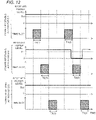
- Fig. 17 is a timing chart showing changes in the lengths of the time slots allocated to the power receiving apparatuses 2-1 to 2-3, in the case where the received power level of the power receiving apparatus 2-2 of Fig. 12 becomes smaller than the threshold Th1 in the time slot T2(2).
- the power transmitting control circuit 10 shortens the time slots T1(1), T3(1) (referred to as "third time slots") allocated to the power receiving apparatuses 2-1, 2-3 different from the power receiving apparatus 2-2 to which the time slots T2(1), T2(2) are allocated, the time slots T1(1), T3(1) being adjacent in time to the time slot T2(1).
- Fig. 18 is a timing chart showing a modified embodiment of changes in the lengths of the time slots allocated to the power receiving apparatuses 2-1 to 2-3, in the case where the received power level of the power receiving apparatus 2-2 of Fig. 12 becomes smaller than the threshold Th1 in the time slot T2(2).
- the power transmitting control circuit 10 extends the time slots T1(2), T3 (2) (referred to as "fourth time slots") allocated to the power receiving apparatuses 2-1, 2-3 to which the time slots T1(1), T3(1) are allocated, the time slots T1(2), T3 (2) being adjacent in time to the time slot T2(2).
- power transmission from the power transmitting apparatus 1 to the power receiving apparatus 2-2 may be stopped in the time slot T2(2).
- Figs. 17 and 18 by effectively using radio resources for the plurality of power receiving apparatuses 2it is possible to wirelessly transmit the power from the power transmitting apparatus 1 to the power receiving apparatuses 2 so that the sensor 23 is less likely to fail due to power shortage.
- the wireless power transmission system of the second embodiment by changing the lengths of the time slots allocated to the power receiving apparatuses 2, it is possible to wirelessly transmit the power from the power transmitting apparatus 1 to the power receiving apparatuses 2 so that the sensor 23 is less likely to fail due to power shortage.
- the power transmitting control circuit 10 may extend the second time slot allocated to the same power receiving apparatus 2, the second time slot preceding or following the first time slot, and further, when the transition occurs from the state where the received power level is smaller than the predetermined threshold Th1, to the state where the received power level is equal to or higher than the predetermined threshold Th1, the power transmitting control circuit 10 may wait for the predetermined standby time Tw, and then, transmit the control signal to operate the sensor 23, using the signal transmitting circuit 13.
- Tw the predetermined standby time
- the antenna device ANT2 of the power receiving apparatus 2 may also have variable directivity (directional pattern).
- the display device may be provided in another apparatus, for example, in the control apparatus 3, instead of in the power transmitting apparatus 1.
- the power receiving apparatus 2 and the like may be provided with any other load device, instead of or in addition to the sensor 23.
- the other load device may be, for example, a lighting device, a switch or a relay configured to control other devices, or a signal processing circuit configured to output a signal to other devices.
- the power receiving apparatus may control the other load device using the detection result of the sensor 23 as a trigger.
- the wireless power transmitting apparatuses and the wireless power transmission systems according to the aspects of the present disclosure may be expressed as follows.
- a wireless power transmitting apparatus wirelessly transmits power to at least one wireless power receiving apparatus 2.
- the wireless power receiving apparatus 2 is provided with a load device configured to operate with power of a power storage device 22.
- the wireless power transmitting apparatus 1 is provided with: a power transmitting circuit 12 configured to transmit power for operating the load device, to the wireless power receiving apparatus 2; a signal transmitting circuit 13 configured to transmit a control signal to control the load device, to the wireless power receiving apparatus 2; a signal receiving circuit 15 configured to obtain an estimated value of a received power level indicating a level of the power transmitted from the wireless power transmitting apparatus 1 and received by the wireless power receiving apparatus 2; and a power transmitting control circuit 10 configured to control operation of the wireless power transmitting apparatus 1.
- the power transmitting control circuit 10 periodically allocates a plurality of time slots to the wireless power receiving apparatus 2, so that in each of the plurality of time slots, the wireless power transmitting apparatus 1 wirelessly transmits the power to the wireless power receiving apparatus 2.
- the power transmitting control circuit 10 extends a second time slot allocated to the one wireless power receiving apparatus 2, the second time slot preceding or following the first time slot.
- the power transmitting control circuit 10 shortens a third time slot allocated to another wireless power receiving apparatus 2 different from the wireless power receiving apparatus 2 to which the first and second time slots are allocated, the third time slot being adjacent in time to the second time slot.
- the power transmitting control circuit 10 extends a fourth time slot allocated to a same wireless power receiving apparatus 2 as the wireless power receiving apparatus to which the third time slot is allocated, the fourth time slot being adjacent in time to the first time slot.
- the power transmitting control circuit 10 waits for a predetermined standby time, and then transmits the control signal using the signal transmitting circuit 13.
- the power transmitting control circuit 10 generates a state signal based on the received power level, the state signal indicating whether or not the load device is operable.
- the wireless power transmitting apparatus 1 is further provided with an interface circuit 17 configured to output the state signal to an external apparatus.
- a wireless power transmitting apparatus 1 wirelessly transmits power to at least one wireless power receiving apparatus 2.
- the wireless power receiving apparatus 2 is provided with a load device configured to operate with power of a power storage device 22.
- the wireless power transmitting apparatus 1 is provided with: a power transmitting circuit 12 configured to transmit power for operating the load device, to the wireless power receiving apparatus 2; a signal transmitting circuit 13 configured to transmit a control signal to control the load device, to the wireless power receiving apparatus 2; a signal receiving circuit 15 configured to obtain an estimated value of a received power level indicating a level of the power transmitted from the wireless power transmitting apparatus 1 and received by the wireless power receiving apparatus 2; and a power transmitting control circuit 10 configured to control operation of the wireless power transmitting apparatus 1.
- the power transmitting control circuit 10 waits for a predetermined standby time, and then transmits the control signal to operate the load device, using the signal transmitting circuit 13.
- the power transmitting control circuit 10 generates a state signal based on the received power level, the state signal indicating whether or not the load device is operable.
- the wireless power transmitting apparatus 1 is further provided with an interface circuit 17 configured to output the state signal to an external apparatus.
- a wireless power transmission system is provided with :the wireless power transmitting apparatus 1 of one of the first to seventh aspects; and at least one wireless power receiving apparatus 2 provided with a load device configured to operate with power of a power storage device 22.
- the wireless power receiving apparatus 2 is provided with a sensor 23 configured to measure a predetermined physical quantity, and wirelessly transmits the physical quantity measured by the sensor 23, to the wireless power transmitting apparatus 1.
- the wireless power transmission system can be used, for example, to supply power to a plurality of sensors in a sensor network including the sensors.
Landscapes
- Engineering & Computer Science (AREA)
- Power Engineering (AREA)
- Computer Networks & Wireless Communication (AREA)
- Transmitters (AREA)
- Charge And Discharge Circuits For Batteries Or The Like (AREA)
Abstract
Description
- The present disclosure relates to a wireless power transmission system including a wireless power transmitting apparatus, and a wireless power receiving apparatus, and also relates to the wireless power transmitting apparatus of the wireless power transmission system.
- There has been known a wireless power transmission system for wirelessly transmitting power from a power transmitting apparatus connected to a power source, to a power receiving apparatus including a load device, such as a rechargeable battery. For example, in a sensor network including a plurality of sensors, a wireless power transmission system including a wireless power transmitting apparatus and a wireless power receiving apparatus is constructed in order to supply power to the sensors.
- When a radio wave propagation environment around the wireless power transmitting apparatus and/or the wireless power receiving apparatus is constantly changing due to movement of a person or an item, it is necessary to adjust operating parameters of the wireless power transmitting apparatus or the wireless power receiving apparatus in accordance with the changes in the radio wave propagation environment.
-
Patent Document 1 discloses a power transmitting apparatus configured to increase transmitting power in accordance with surrounding conditions. - PATENT DOCUMENT 1: Japanese Patent Laid-open Publication No.
JP 2018-102087 A - Power transmission from the wireless power transmitting apparatus to the wireless power receiving apparatus may temporarily fail due to changes in the radio wave propagation environment, and as a result, the load device may not operate normally due to power shortage. For example, in the case where the load device is a sensor, malfunction of the sensor causes an error in a measured value, resulting in malfunction of other apparatuses using the measured value of the sensor (e.g., a manufacturing apparatus in a factory, or the like). Therefore, regardless of changes in the radio wave propagation environment, it is required to wirelessly transmit power from the wireless power transmitting apparatus to the wireless power receiving apparatus, so that the load device is less likely to fail due to power shortage.
- An object of the present disclosure is to provide a wireless power transmitting apparatus capable of wirelessly transmitting power to a wireless power receiving apparatus so that a load device is less likely to fail due to power shortage. In addition, another object of the present disclosure is to provide a wireless power transmission system including such a wireless power transmitting apparatus.
- According to a wireless power transmitting apparatus of an aspect of the present disclosure, the wireless power transmitting apparatus wirelessly transmits power to at least one wireless power receiving apparatus. The wireless power receiving apparatus is provided with a load device configured to operate with power of a power storage device. The wireless power transmitting apparatus is provided with: a power transmitting circuit configured to transmit power for operating the load device, to the wireless power receiving apparatus; a signal transmitting circuit configured to transmit a control signal to control the load device, to the wireless power receiving apparatus; a signal receiving circuit configured to obtain an estimated value of a received power level indicating a level of the power transmitted from the wireless power transmitting apparatus and received by the wireless power receiving apparatus; and a control circuit configured to control operation of the wireless power transmitting apparatus. The control circuit periodically allocates a plurality of time slots to the wireless power receiving apparatus, so that in each of the plurality of time slots, the wireless power transmitting apparatus wirelessly transmits the power to the wireless power receiving apparatus. When the received power level is smaller than a predetermined threshold in a first time slot allocated to one wireless power receiving apparatus, the control circuit extends a second time slot allocated to the one wireless power receiving apparatus, the second time slot preceding or following the first time slot.
- With such a configuration, it is possible to wirelessly transmit power from the wireless power transmitting apparatus to the wireless power receiving apparatus, so that the load device is less likely to fail due to power shortage.
- According to a wireless power transmitting apparatus of an aspect of the present disclosure, the wireless power transmitting apparatus wirelessly transmits power to at least one wireless power receiving apparatus. The wireless power receiving apparatus is provided with a load device configured to operate with power of a power storage device. The wireless power transmitting apparatus is provided with: a power transmitting circuit configured to transmit power for operating the load device, to the wireless power receiving apparatus; a signal transmitting circuit configured to transmit a control signal to control the load device, to the wireless power receiving apparatus; a signal receiving circuit configured to obtain an estimated value of a received power level indicating a level of the power transmitted from the wireless power transmitting apparatus and received by the wireless power receiving apparatus; and a control circuit configured to control operation of the wireless power transmitting apparatus. When a transition occurs from a state where the received power level is smaller than a predetermined threshold, to a state where the received power level is equal to or higher than the threshold, the control circuit waits for a predetermined standby time, and then transmits the control signal to operate the load device, using the signal transmitting circuit.
- With such a configuration, it is possible to wirelessly transmit power from the wireless power transmitting apparatus to the wireless power receiving apparatus, so that the load device is less likely to fail due to power shortage.
- According to a wireless power transmission system of an aspect of the present disclosure, the wireless power transmission system is provided with: the wireless power transmitting apparatus; and at least one wireless power receiving apparatus provided with a load device configured to operate with power of a power storage device.
- With such a configuration, for example, it is possible to supply power to a plurality of sensors in a sensor network including the sensors.
- According to the wireless power transmission system according to the aspect of the present disclosure, it is possible to wirelessly transmit power from the wireless power transmitting apparatus to the wireless power receiving apparatus, so that the load device is less likely to fail due to power shortage.
-
-
Fig. 1 is a schematic diagram showing a configuration of a system including a wireless power transmission system according to a first embodiment. -
Fig. 2 is a block diagram showing a configuration of a wirelesspower transmitting apparatus 1 ofFig. 1 . -
Fig. 3 is a block diagram showing a configuration of a wirelesspower receiving apparatus 2 ofFig. 1 . -
Fig. 4 is a timing chart showing variations in a charging voltage and a state signal, in the case where a received power level of the wirelesspower receiving apparatus 2 ofFig. 1 constantly exceeds a threshold Th1. -
Fig. 5 is a timing chart showing an example of variations in the charging voltage and the state signal, in the case where the received power level of the wirelesspower receiving apparatus 2 ofFig. 1 becomes smaller than the threshold Th1. -
Fig. 6 is a timing chart showing another example of variations in the charging voltage and the state signal, in the case where the received power level of the wirelesspower receiving apparatus 2 ofFig. 1 becomes smaller than the threshold Th1. -
Fig. 7 is a sequence diagram showing one example of operation of the system ofFig. 1 . -
Fig. 8 is a flowchart showing sensing process executed by the power transmittingcontrol circuit 10 of the wirelesspower transmitting apparatus 1 ofFig. 1 . -
Fig. 9 is a sequence diagram showing a modified embodiment of the operation of the system ofFig. 1 . -
Fig. 10 is a schematic diagram showing a configuration of a wirelesspower transmitting apparatus 1A of a wireless power transmission system according to a modified embodiment of the first embodiment. -
Fig. 11 is a schematic diagram showing a configuration of a wirelesspower receiving apparatus 2A of a wireless power transmission system according to a modified embodiment of the first embodiment. -
Fig. 12 is a timing chart showing an initial state of time slots allocated to wireless power receiving apparatuses 2-1 to 2-3 of the wireless power transmission system according to a second embodiment. -
Fig. 13 is a timing chart showing variations in transmitted power and a charging voltage associated with the wireless power receiving apparatus 2-1, in the case where the received power level of the wireless power receiving apparatus 2-1 ofFig. 12 constantly exceeds the threshold Th1. -
Fig. 14 is a timing chart showing variations in the transmitted power and the charging voltage associated with the wireless power receiving apparatus 2-2, in the case where the received power level of the wireless power receiving apparatus 2-2 ofFig. 12 becomes smaller than the threshold Th1 in a time slot T2(2), but lengths the time slots are not changed. -
Fig. 15 is a timing chart showing variations in the transmitted power and the charging voltage associated with the wireless power receiving apparatus 2-2, in the case where the received power level of the wireless power receiving apparatus 2-2 ofFig. 12 becomes smaller than the threshold Th1 in the time slot T2(2), and a preceding time slot T2(1) is extended. -
Fig. 16 is a timing chart showing variations in the transmitted power and the charging voltage associated with the wireless power receiving apparatus 2-2, in the case where the received power level of the wireless power receiving apparatus 2-2 ofFig. 12 becomes smaller than the threshold Th1 in the time slot T2(2), and a following time slot T2(3) is extended. -
Fig. 17 is a timing chart showing changes in lengths of the time slots allocated to the wireless power receiving apparatuses 2-1 to 2-3, in the case where the received power level of the wireless power receiving apparatus 2-2 ofFig. 12 becomes smaller than the threshold Th1 in the time slot T2(2). -
Fig. 18 is a timing chart showing a modified embodiment of changes in the lengths of the time slots allocated to the wireless power receiving apparatuses 2-1 to 2-3, in the case where the received power level of the wireless power receiving apparatus 2-2 ofFig. 12 becomes smaller than the threshold Th1 in the time slot T2(2). - Hereinafter, embodiments according to one aspect of the present disclosure (hereinafter, also referred to as "the present embodiment") will be described with reference to the drawings. In the drawings, the same reference sign indicates similar components.
- A wireless power transmission system according to a first embodiment will be described with reference to
Figs. 1 to 11 . -
Fig. 1 is a schematic diagram showing a configuration of a system including a wireless power transmission system according to the first embodiment. The wireless power transmission system ofFig. 1 includes a wirelesspower transmitting apparatus 1 and at least one wireless power receiving apparatus 2-1 to 2-3, and wirelessly transmits power from the wirelesspower transmitting apparatus 1 to the wireless power receiving apparatuses 2-1 to 2-3. - Hereinafter, the wireless power receiving apparatuses 2-1 to 2-3 are collectively referred to as "wireless
power receiving apparatus 2". AlthoughFig. 1 shows a case where the wireless power transmission system includes the three wireless power receivingapparatuses 2, the wireless power transmission system may include any number of wirelesspower receiving apparatuses 2. In addition, hereinafter, the wirelesspower transmitting apparatus 1 is referred to as a "power transmitting apparatus 1", and the wirelesspower receiving apparatus 2 is referred to as a "power receiving apparatus 2". -
Fig. 2 is a block diagram showing a configuration of thepower transmitting apparatus 1 ofFig. 1 . The power transmittingapparatus 1 is provided with at least a power transmittingcontrol circuit 10, a power transmittingcircuit 12, asignal transmitting circuit 13, and asignal receiving circuit 15. The power transmittingcontrol circuit 10 is a control circuit of thepower transmitting apparatus 1, that controls overall operations of thepower transmitting apparatus 1. Thepower transmitting circuit 12 transmits power for operating a sensor 23 (described below) of thepower receiving apparatus 2, to thepower receiving apparatus 2. Thesignal transmitting circuit 13 transmits a control signal to thepower receiving apparatus 2 to control thesensor 23. Thesignal receiving circuit 15 obtains an estimated value of a received power level indicating a level of the power transmitted from thepower transmitting apparatus 1 and received by thepower receiving apparatus 2. -
Fig. 3 is a block diagram showing a configuration of thepower receiving apparatus 2 ofFig. 1 . Thepower receiving apparatus 2 is provided with at least apower storage device 22 and asensor 23. Thepower storage device 22 stores the power wirelessly transmitted from thepower transmitting apparatus 1 to thepower receiving apparatus 2. Thepower storage device 22 includes, for example, a rechargeable battery or a capacitor. Thesensor 23 is a load device operable with the power stored in thepower storage device 22. - When a transition occurs from a state where the received power level is smaller than a predetermined threshold Th1, to a state where the received power level is equal to or higher than the threshold Th1, the power
transmitting control circuit 10 waits for a predetermined standby time Tw, and then transmits the control signal to operate thesensor 23, using thesignal transmitting circuit 13. - When the
power storage device 22 has a charging voltage higher than a predetermined threshold Th2, thepower storage device 22 can supply thesensor 23 with power allowing thesensor 23 to operate stably. The threshold Th1 of the received power level may be set, for example, so that the charging voltage of thepower storage device 22 reaches the threshold Th2 after a sufficiently long time has elapsed. - For example, when an obstacle passes through between the
power transmitting apparatus 1 and thepower receiving apparatus 2, radio waves are blocked, the received power level decreases, and the charging voltage of thepower storage device 22 also decreases. Once the power transmission is interrupted, and the charging voltage of thepower storage device 22 decreases below the threshold Th2, even when the power transmission is resumed, it takes some time dependent on a time constant of the circuit, for the charging voltage of thepower storage device 22 to becomes equal to or higher than the threshold Th2. Therefore, the standby time Tw is set to, for example, a time length during which the charging voltage of thepower storage device 22 increases from zero to the threshold Th2, when thepower receiving apparatus 2 is receiving the power at a standard received power level higher than thethreshold Th 1. - According to the wireless power transmission system of the first embodiment, when a transition occurs from the state where the received power level is smaller than the threshold Th1, to the state where the received power level is equal to or higher than the threshold Th1, the control signal to operate the
sensor 23 is transmitted after the standby time Tw has elapsed, as described above. At this time, since it is considered that the charging voltage of thepower storage device 22 is equal to or higher than the threshold Th2, it is possible to supply thesensor 23 with the power allowing thesensor 23 to operate stably. As a result, it is possible to wirelessly transmit the power from thepower transmitting apparatus 1 to thepower receiving apparatus 2 so that thesensor 23 is less likely to fail due to power shortage. - The control signal to operate the
sensor 23 may include, for example, turning on thesensor 23, measuring a predetermined physical quantity by thesensor 23, reading the physical quantity measured by thesensor 23, and the like. - Referring to the example of
Fig. 1 , thepower transmitting apparatus 1 and the power receiving apparatuses 2-1 to 2-3 are provided in a factory including acontrol apparatus 3, amanufacturing apparatus 4, and abelt conveyor 5. Thebelt conveyor 5 conveys apallet 6 and aworkpiece 7. Thepallet 6 and theworkpiece 7 are moved by thebelt conveyor 5 so as to arrive at predetermined positions p1 to p3 at predetermined times. At each of the positions p1 to p3, a predetermined work event is executed on theworkpiece 7. The power receiving apparatuses 2-1 to 2-3 are provided near the positions p1 to p3, respectively, and are associated with the events executed at the positions p1 to p3, respectively. Thesensors 23 of the power receiving apparatuses 2-1 to 2-3 measure predetermined physical quantities associated with these events. Thepower transmitting apparatus 1 collects the measured physical quantities from the power receiving apparatus 2-1 to 2-3, and sends the physical quantities to thecontrol apparatus 3. Thecontrol apparatus 3 controls operations of themanufacturing apparatus 4 based on the measured physical quantity. Thecontrol apparatus 3 is, for example, a programmable logic controller. Themanufacturing apparatus 4 executes a predetermined work event (e.g., a fabrication process, such as welding) on theworkpiece 7. - The
power transmitting apparatus 1 is connected to thecontrol apparatus 3 and themanufacturing apparatus 4 as external apparatuses. - Referring to
Fig. 2 , thepower transmitting apparatus 1 is provided with the powertransmitting control circuit 10, apower supply device 11, thepower transmitting circuit 12, thesignal transmitting circuit 13, anantenna control circuit 14, thesignal receiving circuit 15, acirculator 16, an antenna device ANT1, and an interface (I/F)circuit 17, and adisplay device 18. - The power
transmitting control circuit 10 controls the overall operations of thepower transmitting apparatus 1, as described above. - The
power supply device 11 supplies power to be transmitted to thepower receiving apparatus 2. - The
power transmitting circuit 12 transmits the power for operating thesensor 23 of thepower receiving apparatus 2 as described above, to thepower receiving apparatus 2, via thecirculator 16 and the antenna device ANT1. Thepower transmitting circuit 12 generates, for example, a continuous wave (CW) from the power supplied by thepower supply device 11. - The
signal transmitting circuit 13 transmits the control signal to control the sensor 23 (e.g., a read signal of the sensor 23), to thepower receiving apparatus 2, via thecirculator 16 and the antenna device ANT1. Thesignal receiving circuit 15 receives, for example, a response signal including the physical quantity measured by thesensor 23, from thepower receiving apparatus 2, via the antenna device ANT1 and thecirculator 16. In addition, thesignal receiving circuit 15 obtains the estimated value of the received power level, as described above. The estimated value of the received power level may be generated by thepower transmitting apparatus 1 as described below, or may be generated by thepower receiving apparatus 2 and received from thepower receiving apparatus 2 via the antenna device ANT1 and thecirculator 16. - The antenna device ANT1 has variable directivity (directional pattern). The antenna device ANT1 is, for example, an array antenna including a plurality of antenna elements, and its directivity changes by individually adjusting amplitudes and phases of signals transmitted or received by the antenna elements. The
antenna control circuit 14 controls the directivity of the antenna device ANT1 under the control of the powertransmitting control circuit 10. - The
circulator 16 combines and separates the power and the signal transmitted to thepower receiving apparatus 2 via the antenna device ANT1, with/from the signal received from thepower receiving apparatus 2 via the antenna device ANT1. - The
interface circuit 17 is connected to thecontrol apparatus 3 via a wired or wireless communication line. As will be described below, the powertransmitting control circuit 10 generates a state signal indicating whether or not thesensor 23 is operable, and outputs the state signal to thecontrol apparatus 3 via theinterface circuit 17. In addition, as will be described below, the powertransmitting control circuit 10 generates a read result signal including the physical quantity measured by thesensor 23, and transmits the read result signal to thecontrol apparatus 3 via theinterface circuit 17. - The
display device 18 displays a state of thepower transmitting apparatus 1, and a state of the power receiving apparatus 2 (the received power level, and the like) communicably connected to thepower transmitting apparatus 1. - Referring to
Fig. 3 , thepower receiving apparatus 2 is provided with a powerreceiving control circuit 20, apower converter circuit 21, thepower storage device 22, thesensor 23, a matchingcircuit 24, acirculator 25, asignal transmitting circuit 26, asignal receiving circuit 27, apower receiving circuit 28, and an antenna device ANT2, and a switch SW. - The power
receiving control circuit 20 controls overall operations of thepower receiving apparatus 2. - The antenna device ANT2 has a predetermined directional pattern or omni-directional pattern.
- The matching
circuit 24 matches an impedance of the antenna device ANT2 with impedances of thecirculator 25 and the other circuits. - The
circulator 25 combines and separates the power and the signal transmitted from thepower transmitting apparatus 1 via the antenna device ANT2, with/from the signal transmitted to thepower transmitting apparatus 1 via the antenna device ANT2. - The
signal transmitting circuit 26 transmits, for example, the response signal including the physical quantity measured by thesensor 23, via thecirculator 25, the matchingcircuit 24, and the antenna device ANT2. Thesignal receiving circuit 27 receives the control signal to control thesensor 23, from thepower transmitting apparatus 1, via the antenna device ANT2, the matchingcircuit 24, and thecirculator 25. - The
power receiving circuit 28 receives the power for operating thesensor 23, from thepower transmitting apparatus 1, via the antenna device ANT2, the matchingcircuit 24, and thecirculator 25. - The
power converter circuit 21 converts (rectifies) the power wirelessly transmitted from thepower transmitting apparatus 1 to thepower receiving apparatus 2, from an alternating current to a direct current, and then, boosts or drops the direct current power. Thepower storage device 22 stores the power wirelessly transmitted from thepower transmitting apparatus 1 to thepower receiving apparatus 2, and then boosted or dropped by thepower converter circuit 21. Thepower storage device 22 includes, for example, a rechargeable battery or a capacitor. - The
sensor 23 operates with the power stored in thepower storage device 22, and measures the predetermined physical quantity. Thesensor 23 is connected to the powerreceiving control circuit 20 via the switch SW configured to turn on/off under the control of the powerreceiving control circuit 20. When the switch SW is turned on, the power is supplied from thepower storage device 22 to thesensor 23, and the physical quantity measured by thesensor 23 is sent to the powerreceiving control circuit 20. The physical quantity measured by thesensor 23 is wirelessly transmitted to thepower transmitting apparatus 1. - In order to estimate the received power level, the
signal transmitting circuit 26 of thepower receiving apparatus 2 may wirelessly transmit a test signal, and thesignal receiving circuit 15 of thepower transmitting apparatus 1 may wirelessly receive the test signal to measure a received signal intensity of the test signal. Thesignal receiving circuit 15 of thepower transmitting apparatus 1 may measure the received signal intensity of the test signal as it is, or measure a received signal intensity of an amplified test signal, or measure power of the test signal, instead of the received signal intensity of the test signal. - In order to estimate the received power level, the
signal transmitting circuit 13 of thepower transmitting apparatus 1 may wirelessly transmit a test signal, and thesignal receiving circuit 27 of thepower receiving apparatus 2 may wirelessly receive the test signal to measure a received signal intensity of the test signal. Thesignal receiving circuit 27 of thepower receiving apparatus 2 may measure the received signal intensity of the test signal as it is, or measure a received signal intensity of an amplified test signal, or measure the power of the test signal, instead of the received signal intensity of the test signal. - In order to estimate the received power level, the
signal transmitting circuit 13 of thepower transmitting apparatus 1 may wirelessly transmit a test signal, and thesignal receiving circuit 15 of thepower transmitting apparatus 1 may wirelessly receive the test signal reflected by thepower receiving apparatus 2, and measure a received signal intensity of the test signal. In this case, in order to reflect the test signal transmitted from thepower transmitting apparatus 1, thepower receiving apparatus 2 may be configured, for example, so that impedance mismatching is made selectively in any of the circuit portions under the control of the powerreceiving control circuit 20. - The test signal may be a communication signal with a predetermined format, or may be a continuous wave (CW). In addition, the test signal may be transmitted in response to a command signal generated by the
power transmitting apparatus 1 or thepower receiving apparatus 2, or may be transmitted periodically without the command signal. - In order to estimate the received power level, the charging voltage of the
power storage device 22 may be measured. - In order to estimate the received power level, the power supplied to the load device of the
power receiving apparatus 2, for example, thepower converter circuit 21, thepower storage device 22, or thesensor 23, may be measured. - Environments around the
power transmitting apparatus 1 and thepower receiving apparatuses 2 ofFig. 1 differ in various aspects, between installation of thepower transmitting apparatus 1 and thepower receiving apparatuses 2 in a factory, and actual operation of the factory. For example, during installation, themanufacturing apparatus 4 and thebelt conveyor 5 are stopped, and on the other hand, during operation, themanufacturing apparatus 4 and thebelt conveyor 5 are operating, and thepallet 6 and theworkpiece 7 pass through near thepower transmitting apparatus 1 and thepower receiving apparatuses 2 - When the environment around the
power transmitting apparatus 1 and thepower receiving apparatuses 2 change, the radio wave propagation environment also changes. Therefore, even if main beam directions of the antenna devices ANT1 and ANT2 are adjusted during installation, that is, the main beam direction of the antenna device ANT1 of thepower transmitting apparatus 1 is adjusted to a position of each of thepower receiving apparatuses 2, and the main beam direction of the antenna device ANT2 of each of thepower receiving apparatuses 2 is adjusted to a position of thepower transmitting apparatus 1, propagation paths of radio waves may change or be blocked during operation. As a result, the received power level of any of thepower receiving apparatuses 2 becomes smaller than the threshold Th1, and therefore, the power allowing thesensor 23 to operate stably cannot be supplied to thesensor 23. If thesensor 23 fails due to power shortage, defects may occur in products fabricated by themanufacturing apparatus 4, or malfunction of themanufacturing apparatus 4 may occur. - The wireless power transmission system according to the first embodiment wirelessly transmits the power from the
power transmitting apparatus 1 to thepower receiving apparatus 2 so that thesensor 23 is less likely to fail due to power shortage, as described below. -
Fig. 4 is a timing chart showing variations in the charging voltage and the state signal, in the case where the received power level of thepower receiving apparatus 2 ofFig. 1 constantly exceeds the threshold Th1. The powertransmitting control circuit 10 generates the state signal based on the received power level, the state signal indicating whether or not thesensor 23 is operable, that is, whether or not the power allowing thesensor 23 to operate stably can be supplied from thepower storage device 22 to thesensor 23. As described above, when the received power level is equal to or higher than the threshold Th1, the charging voltage of thepower storage device 22 becomes equal to or higher than the threshold Th2, and therefore, it is possible to supply thesensor 23 with the power allowing thesensor 23 to operate stably. In the example ofFig. 4 , the state signal is constantly high, and indicates that thesensor 23 is constantly operable (enabled). - The
display device 18 may display at least one of the received power level, the charging voltage, and the state signal shown inFig. 4 . -
Fig. 5 is a timing chart showing an example of variations in the charging voltage and the state signal, in the case where the received power level of thepower receiving apparatus 2 ofFig. 1 becomes smaller than the threshold Th1. As described above, when the factory is in operation, themanufacturing apparatus 4 and thebelt conveyor 5 operate, and thepallet 6 and theworkpiece 7 pass through near thepower transmitting apparatus 1 and thepower receiving apparatus 2. As a result, the propagation of radio waves is periodically blocked between thepower transmitting apparatus 1 and thepower receiving apparatus 2, the received power level periodically decreases below the threshold Th1, and the charging voltage of thepower storage device 22 also periodically decreases below the threshold Th2. In this case, the powertransmitting control circuit 10 sets the state signal to low. As described above, once the power transmission is interrupted, and the charging voltage of thepower storage device 22 decreases below the threshold Th2, even when the power transmission is resumed, it takes some time depending on the time constant of the circuit, for the charging voltage of thepower storage device 22 to become equal to or higher than the threshold Th2. Therefore, when the transition occurs from the state where the received power level is smaller than the threshold Th1, to the state where the received power level is equal to or higher than the threshold Th1, the powertransmitting control circuit 10 waits for the standby time Tw, and then, transits the state signal from low to high. -
Fig. 6 is a timing chart showing another example of variations in the charging voltage and the state signal, in the case where the received power level of thepower receiving apparatus 2 ofFig. 1 becomes smaller than the threshold Th1. The example ofFig. 5 shows that thesensor 23 is operable (enabled) when the state signal is high, and thesensor 23 is inoperable (disabled) when the state signal is low. On the other hand, as shown inFig. 6 , thesensor 23 may be operable (enabled) when the state signal is low, and thesensor 23 may be inoperable (disabled) when the state signal is high. - A plurality of time slots for wirelessly transmitting the power from the
power transmitting apparatus 1 to thepower receiving apparatuses 2 are periodically allocated to thepower receiving apparatuses 2. In each one of the time slots, the following steps are executed in a time-division manner: - (1) estimating the received power level (i.e., transmitting and receiving the test signal),
- (2) wirelessky transmitting the power, and
- (3) transmitting and receiving the control signal to control the
sensor 23, and the measured physical quantity. -
Fig. 7 is a sequence diagram showing one example of operation of the system ofFig. 1 . - The
power transmitting apparatus 1 obtains the estimated values of the received power levels of thepower receiving apparatuses 2 in advance, and sets the state signals of thepower receiving apparatuses 2 based on the received power levels. - When the
manufacturing apparatus 4 itself is ready to operate, themanufacturing apparatus 4 transmits a sensing request signal to thecontrol apparatus 3 to operate thesensors 23 of thepower receiving apparatuses 2. - Next, the
control apparatus 3 transmits a read start signal to thepower transmitting apparatus 1 to start reading the measured value of thesensor 23. - Next, the
power transmitting apparatus 1 transmits the state signal to thecontrol apparatus 3. When thesensor 23 is inoperable (disabled), thecontrol apparatus 3 repeatedly transmits the read start signal to thepower transmitting apparatus 1, until thesensor 23 becomes operable (enabled). When thesensor 23 is operable (enabled), thecontrol apparatus 3 transmits a read request signal to thepower transmitting apparatus 1 to request thepower transmitting apparatus 1 to read the measured values of thesensors 23. - Next, the
power transmitting apparatus 1 transmits the read signal to thepower receiving apparatus 2 to read the measured value of thesensor 23. Next, thepower receiving apparatus 2 transmits the response signal to thepower transmitting apparatus 1, the response signal including the physical quantity measured by thesensor 23. Next, thepower transmitting apparatus 1 transmits the read result signal to thecontrol apparatus 3, the read result signal including the physical quantity measured by thesensor 23. - Next, the
control apparatus 3 determines whether or not the physical quantity measured by thesensor 23 satisfies a predetermined criterion (e.g., a criterion indicating that themanufacturing apparatus 4 may operate), and transmits a sensing completion signal including a result of the determination, to themanufacturing apparatus 4. Thereafter, thecontrol apparatus 3 transmits a control signal to themanufacturing apparatus 4 to control themanufacturing apparatus 4. -
Fig. 8 is a flowchart showing sensing process executed by the powertransmitting control circuit 10 of thepower transmitting apparatus 1 ofFig. 1 . - In step S1, the power
transmitting control circuit 10 obtains the estimated values of the received power levels of thepower receiving apparatuses 2, using thesignal receiving circuit 15. In step S2, the powertransmitting control circuit 10 determines whether or not the received power level is equal to or higher than the threshold Th1; if YES, the process proceeds to step S3, and if NO, the process proceeds to step S12. - In step S3, the power
transmitting control circuit 10 determines whether or not the state signal indicates "disabled"; if YES, the process proceeds to step S4, and if NO, the process proceeds to step S6. If YES in step S3, then in step S4, the powertransmitting control circuit 10 waits for the standby period Tw, while the state signal remains indicating "disabled", and in step S5, the powertransmitting control circuit 10 transitions indication of the state signal from "disabled" to "enabled". On the other hand, if NO in step S3, the powertransmitting control circuit 10 keeps the state signal indicating "enabled". - In step S6, the power
transmitting control circuit 10 determines whether or not the read start signal has been received from thecontrol apparatus 3; if YES, the process proceeds to step S7, and if NO, the process proceeds to step S8. In step S7, the powertransmitting control circuit 10 transmits a state signal to thecontrol apparatus 3. - In step S8, the power
transmitting control circuit 10 determines whether or not the read request signal has been received from thecontrol apparatus 3; if YES, the process proceeds to step S9, and if NO, the process returns to step S1. In step S9, the powertransmitting control circuit 10 transmits the read signal to thepower receiving apparatus 2. When the powerreceiving control circuit 20 receives the read signal, the powerreceiving control circuit 20 obtains the physical quantity measured by thesensor 23. In step S10, the powertransmitting control circuit 10 receives the response signal from thepower receiving apparatus 2, the response signal including the physical quantity measured by thesensor 23. In step S11, the powertransmitting control circuit 10 transmits the read result signal to thecontrol apparatus 3, the read result signal including the physical quantity measured by thesensor 23. - If NO in step S2, then in step S12, the power
transmitting control circuit 10 sets the indication of the state signal to "disabled". - According to the wireless power transmission system of the first embodiment, by executing the process of
Figs. 7 and8 , it is possible to wirelessly transmit the power from thepower transmitting apparatus 1 to thepower receiving apparatus 2 so that thesensor 23 is less likely to fail due to power shortage. -
Fig. 9 is a sequence diagram showing a modified embodiment of the operation of the system ofFig. 1 . The system ofFig. 1 repeats the operation ofFig. 7 , and therefore, thecontrol apparatus 3 collects the state signals each indicating whether or not thesensor 23 of each of thepower receiving apparatuses 2 is operable. Referring toFig. 9 , among the steps ofFig. 7 , steps other than those related to generating and transmitting the state signals are omitted for ease of illustration. When thecontrol apparatus 3 collects the state signals of thepower receiving apparatuses 2 over a predetermined time length, thecontrol apparatus 3 executes automatic scheduling process based on the collected state signals, for automatically scheduling the operations of themanufacturing apparatus 4. According to the automatic scheduling process, thecontrol apparatus 3 extracts time periods when thesensors 23 are operable, and time periods when thesensor 23 is inoperable, from the collected state signals, and schedules the operations of themanufacturing apparatus 4 so that themanufacturing apparatus 4 operates in the time period when thesensors 23 are operable. -
Fig. 10 is a schematic diagram showing a configuration of apower transmitting apparatus 1A of a wireless power transmission system according to a modified embodiment of the first embodiment. Thepower transmitting apparatus 1A is provided with antenna devices ANT11 and ANT12, and anantenna control circuit 14A, instead of the antenna device ANT1, theantenna control circuit 14, and thecirculator 16 ofFig. 2 . The separate antenna devices ANT11, ANT12 may be used, instead of sharing the one antenna device ANT1 for transmitting and receiving. Theantenna control circuit 14A controls directivities (directional patterns) of theantenna devices ANT 11 and ANT12 under control of the powertransmitting control circuit 10. -
Fig. 11 is a schematic diagram showing a configuration of apower receiving apparatus 2A of a wireless power transmission system according to a modified embodiment of the first embodiment. Thepower receiving apparatus 2A is provided with antenna devices ANT21 and ANT22, a powerreceiving control circuit 20A, and matchingcircuits receiving control circuit 20, and thematching circuit 24 ofFig. 3 . The separate antenna devices ANT21, ANT22 may be used, instead of sharing the one antenna device ANT2 for transmitting and receiving. - According to the wireless power transmission system of the first embodiment, when the transition occurs from the state where the received power level is smaller than the threshold Th1, to the state where the received power level is equal to or higher than the threshold Th1, the control signal to operate the
sensor 23 is transmitted after the standby time Tw has elapsed. At this time, since it is considered that the charging voltage of thepower storage device 22 is equal to or higher than the threshold Th2, it is possible to supply thesensor 23 with the power allowing thesensor 23 to operate stably. As a result, it is possible to wirelessly transmit the power from thepower transmitting apparatus 1 to thepower receiving apparatus 2 so that thesensor 23 is less likely to fail due to power shortage. - According to the wireless power transmission system of the first embodiment, it can be applied to a radio wave propagation environment in which the received power level drops periodically, and also applied to a radio wave propagation environment in which the received power level drops non-periodically.
- According to the wireless power transmission system of the first embodiment, the
sensor 23 is less likely to fail, and therefore, defects of the products fabricated by themanufacturing apparatus 4 are less likely occur, and a malfunction of themanufacturing apparatus 4 is less likely occur. - According to the wireless power transmission system of the first embodiment, since the
control apparatus 3 recognizes whether or not thesensors 23 of thepower receiving apparatuses 2 are operable, thecontrol apparatus 3 can operate themanufacturing apparatus 4 in the time period when thesensors 23 are operable, while monitoring the environment around themanufacturing apparatus 4 and thebelt conveyor 5. As a result, defects of the products fabricated by themanufacturing apparatus 4 are less likely occur, and a malfunction of themanufacturing apparatus 4 is less likely occur. - According to the wireless power transmission system of the first embodiment, by visualizing the state of the power receiving apparatus 2 (the received power level and the like) using the
display device 18, for example, a designer of a production lines of the factory can appropriately determine timing of the operations of themanufacturing apparatus 4, thebelt conveyor 5, and the like, in accordance with whether or not thesensors 23 of thepower receiving apparatuses 2 are operable (i.e., changes in the radio wave propagation environment). - A wireless power transmission system according to a second embodiment will be described with reference to
Figs. 12 to 18 . - The wireless power transmission system according to the second embodiment is configured in a similar manner to that of the wireless power transmission system according to the first embodiment. Therefore, repeated description of the configuration will be omitted.
- The power
transmitting control circuit 10 periodically allocates a plurality of time slots to thepower receiving apparatuses 2, so that in each of the plurality oftime slots 2, thepower transmitting apparatus 1 wirelessly transmits the power to thepower receiving apparatuses 2. When the received power level is smaller than thepredetermined threshold Th 1 in a first time slot allocated to one of thepower receiving apparatuses 2, the powertransmitting control circuit 10 extends a second time slot allocated to the samepower receiving apparatus 2, the second time slot preceding or following the first time slot. - For example, when an obstacle passes through between the
power transmitting apparatus 1 and thepower receiving apparatus 2 in a time slot allocated to one of thepower receiving apparatuses 2, the radio waves are blocked, the received power level decreases, and the charging voltage of thepower storage device 22 also decreases. According to the wireless power transmission system of the second embodiment, another time slot allocated to the samepower receiving apparatus 2 is extended in order to compensate for the decrease in the charging voltage. As a result, it is possible to wirelessly transmit the power from thepower transmitting apparatus 1 to thepower receiving apparatuses 2 so that thesensor 23 is less likely to fail due to power shortage. -
Fig. 12 is a timing chart showing initial states of the time slots allocated to the power receiving apparatuses 2-1 to 2-3 of the wireless power transmission system according to the second embodiment. In an example ofFig. 12 , time slots T1(1), T1(2) are allocated to the power receiving apparatus 2-1, time slots T2(1), T2(2) are allocated to the power receiving apparatus 2-2, and time slots T3(1), T3(2) are allocated to the power receiving apparatus 2-3. In the example ofFig. 12 , the received power level of the power receiving apparatus 2-2 becomes smaller than the threshold Th1 in a time interval including the time slot T2(2) allocated to the power receiving apparatus 2-2. -
Fig. 13 is a timing chart showing variations in the transmitted power and the charging voltage associated with the power receiving apparatus 2-1, in the case where the received power level of the power receiving apparatus 2-1 ofFig. 12 constantly exceeds the threshold Th1. In the example ofFig. 13 , the charging voltage constantly exceeds the threshold Th2. -
Fig. 14 is a timing chart showing variations in the transmitted power and the charging voltage associated with the power receiving apparatus 2-2, in the case where the received power level of the power receiving apparatus 2-2 ofFig. 12 becomes smaller than the threshold Th1 in the time slot T2(2), but lengths the time slots are not changed. In the example ofFig. 14 , the received power level becomes smaller than the threshold Th1 in the time slot T2(2) allocated to the power receiving apparatus 2-2 (referred to as a "first time slot"), and therefore, the charging voltage becomes smaller than the threshold Th2. This may result in malfunction of thesensor 23. -
Fig. 15 is a timing chart showing changes of the transmitted power and the charging voltage associated with the power receiving apparatus 2-2, in the case where the received power level of the power receiving apparatus 2-2 ofFig. 12 becomes smaller than the threshold Th1 in the time slot T2(2), and the preceding time slot T2(1) is extended.Fig. 16 is a timing chart showing variations in the transmitted power and the charging voltage associated with the power receiving apparatus 2-2, in the case where the received power level of the power receiving apparatus 2-2 ofFig. 12 becomes smaller than the threshold Th1 in the time slot T2(2), and the following time slot T2(3) is extended. In the examples ofFigs. 15 and 16 , in order to compensate for the decrease in the charging voltage, the time slot T2(1) or the time slot T2(3) (referred to as a "second time slot") allocated to the same power receiving apparatus 2-2 is extended, the time slot T2(1) preceding the time slot T2(2), and the time slot T2(3) following the time slot T2(2). - When the received power level of one of the
power receiving apparatuses 2 decreases periodically, by extending another time slot allocated to the samepower receiving apparatus 2, it is possible to wirelessly transmit the power from thepower transmitting apparatus 1 to thepower receiving apparatuses 2 so that thesensor 23 is less likely to fail due to power shortage. -
Fig. 17 is a timing chart showing changes in the lengths of the time slots allocated to the power receiving apparatuses 2-1 to 2-3, in the case where the received power level of the power receiving apparatus 2-2 ofFig. 12 becomes smaller than the threshold Th1 in the time slot T2(2). The powertransmitting control circuit 10 shortens the time slots T1(1), T3(1) (referred to as "third time slots") allocated to the power receiving apparatuses 2-1, 2-3 different from the power receiving apparatus 2-2 to which the time slots T2(1), T2(2) are allocated, the time slots T1(1), T3(1) being adjacent in time to the time slot T2(1). -
Fig. 18 is a timing chart showing a modified embodiment of changes in the lengths of the time slots allocated to the power receiving apparatuses 2-1 to 2-3, in the case where the received power level of the power receiving apparatus 2-2 ofFig. 12 becomes smaller than the threshold Th1 in the time slot T2(2). The powertransmitting control circuit 10 extends the time slots T1(2), T3 (2) (referred to as "fourth time slots") allocated to the power receiving apparatuses 2-1, 2-3 to which the time slots T1(1), T3(1) are allocated, the time slots T1(2), T3 (2) being adjacent in time to the time slot T2(2). - In the examples of
Figs. 17 and18 , power transmission from thepower transmitting apparatus 1 to the power receiving apparatus 2-2 may be stopped in the time slot T2(2). - According to
Figs. 17 and18 , by effectively using radio resources for the plurality of power receiving apparatuses 2it is possible to wirelessly transmit the power from thepower transmitting apparatus 1 to thepower receiving apparatuses 2 so that thesensor 23 is less likely to fail due to power shortage. - According to the wireless power transmission system of the second embodiment, by changing the lengths of the time slots allocated to the
power receiving apparatuses 2, it is possible to wirelessly transmit the power from thepower transmitting apparatus 1 to thepower receiving apparatuses 2 so that thesensor 23 is less likely to fail due to power shortage. - The features of the first embodiment and the features of the second embodiment may be combined with each other. That is, when the received power level becomes smaller than the
predetermined threshold Th 1 in the first time slot allocated to one of thepower receiving apparatuses 2, the powertransmitting control circuit 10 may extend the second time slot allocated to the samepower receiving apparatus 2, the second time slot preceding or following the first time slot, and further, when the transition occurs from the state where the received power level is smaller than the predetermined threshold Th1, to the state where the received power level is equal to or higher than the predetermined threshold Th1, the powertransmitting control circuit 10 may wait for the predetermined standby time Tw, and then, transmit the control signal to operate thesensor 23, using thesignal transmitting circuit 13. Thus, it is possible to wirelessly transmit the power from thepower transmitting apparatuses 1 to thepower receiving apparatus 2 so that thesensor 23 is much less likely to fail due to power shortage. - The antenna device ANT2 of the
power receiving apparatus 2 may also have variable directivity (directional pattern). - The display device may be provided in another apparatus, for example, in the
control apparatus 3, instead of in thepower transmitting apparatus 1. - The
power receiving apparatus 2 and the like may be provided with any other load device, instead of or in addition to thesensor 23. The other load device may be, for example, a lighting device, a switch or a relay configured to control other devices, or a signal processing circuit configured to output a signal to other devices. In this case, the power receiving apparatus may control the other load device using the detection result of thesensor 23 as a trigger. - The wireless power transmitting apparatuses and the wireless power transmission systems according to the aspects of the present disclosure may be expressed as follows.
- According to the first aspect of the present disclosure, a wireless power transmitting apparatus wirelessly transmits power to at least one wireless
power receiving apparatus 2. The wirelesspower receiving apparatus 2 is provided with a load device configured to operate with power of apower storage device 22. The wirelesspower transmitting apparatus 1 is provided with: apower transmitting circuit 12 configured to transmit power for operating the load device, to the wirelesspower receiving apparatus 2; asignal transmitting circuit 13 configured to transmit a control signal to control the load device, to the wirelesspower receiving apparatus 2; asignal receiving circuit 15 configured to obtain an estimated value of a received power level indicating a level of the power transmitted from the wirelesspower transmitting apparatus 1 and received by the wirelesspower receiving apparatus 2; and a powertransmitting control circuit 10 configured to control operation of the wirelesspower transmitting apparatus 1. - The power
transmitting control circuit 10 periodically allocates a plurality of time slots to the wirelesspower receiving apparatus 2, so that in each of the plurality of time slots, the wirelesspower transmitting apparatus 1 wirelessly transmits the power to the wirelesspower receiving apparatus 2. When the received power level is smaller than a predetermined threshold in a first time slot allocated to one wirelesspower receiving apparatus 2, the powertransmitting control circuit 10 extends a second time slot allocated to the one wirelesspower receiving apparatus 2, the second time slot preceding or following the first time slot. - According to the second aspect of the present disclosure, in the wireless power transmitting apparatus of the first aspect, in the case where the wireless
power transmitting apparatus 1 wirelessly transmits power to a plurality of the wirelesspower receiving apparatuses 2, the powertransmitting control circuit 10 shortens a third time slot allocated to another wirelesspower receiving apparatus 2 different from the wirelesspower receiving apparatus 2 to which the first and second time slots are allocated, the third time slot being adjacent in time to the second time slot. - According to the third aspect of the present disclosure, in the wireless power transmitting apparatus of the second aspect, the power
transmitting control circuit 10 extends a fourth time slot allocated to a same wirelesspower receiving apparatus 2 as the wireless power receiving apparatus to which the third time slot is allocated, the fourth time slot being adjacent in time to the first time slot. - According to the fourth aspect of the present disclosure, in the wireless power transmitting apparatus of one of the first to third aspects, when a transition occurs from a state where the received power level is smaller than a predetermined threshold, to a state where the received power level is equal to or higher than the threshold, the power
transmitting control circuit 10 waits for a predetermined standby time, and then transmits the control signal using thesignal transmitting circuit 13. - According to the fifth aspect of the present disclosure, in the wireless power transmitting apparatus of the fourth aspect, the power
transmitting control circuit 10 generates a state signal based on the received power level, the state signal indicating whether or not the load device is operable. The wirelesspower transmitting apparatus 1 is further provided with aninterface circuit 17 configured to output the state signal to an external apparatus. - According to the sixth aspect of the present disclosure, a wireless
power transmitting apparatus 1 wirelessly transmits power to at least one wirelesspower receiving apparatus 2. The wirelesspower receiving apparatus 2 is provided with a load device configured to operate with power of apower storage device 22. The wirelesspower transmitting apparatus 1 is provided with: apower transmitting circuit 12 configured to transmit power for operating the load device, to the wirelesspower receiving apparatus 2; asignal transmitting circuit 13 configured to transmit a control signal to control the load device, to the wirelesspower receiving apparatus 2; asignal receiving circuit 15 configured to obtain an estimated value of a received power level indicating a level of the power transmitted from the wirelesspower transmitting apparatus 1 and received by the wirelesspower receiving apparatus 2; and a powertransmitting control circuit 10 configured to control operation of the wirelesspower transmitting apparatus 1. When a transition occurs from a state where the received power level is smaller than a predetermined threshold, to a state where the received power level is equal to or higher than the threshold, the powertransmitting control circuit 10 waits for a predetermined standby time, and then transmits the control signal to operate the load device, using thesignal transmitting circuit 13. - According to the seventh aspect of the present disclosure, in the wireless power transmitting apparatus of the sixth aspect, the power
transmitting control circuit 10 generates a state signal based on the received power level, the state signal indicating whether or not the load device is operable. The wirelesspower transmitting apparatus 1 is further provided with aninterface circuit 17 configured to output the state signal to an external apparatus. - According to eighth aspect of the present disclosure, a wireless power transmission system is provided with :the wireless
power transmitting apparatus 1 of one of the first to seventh aspects; and at least one wirelesspower receiving apparatus 2 provided with a load device configured to operate with power of apower storage device 22. - According to ninth second aspect of the present disclosure, in the wireless power transmission system of the eighth aspect, the wireless
power receiving apparatus 2 is provided with asensor 23 configured to measure a predetermined physical quantity, and wirelessly transmits the physical quantity measured by thesensor 23, to the wirelesspower transmitting apparatus 1.. - The wireless power transmission system according to the aspect of the present disclosure can be used, for example, to supply power to a plurality of sensors in a sensor network including the sensors.
-
- 1, 1A: WIRELESS POWER TRANSMITTING APPARATUS (POWER TRANSMITTING APPARATUS)
- 2, 2A, 2-1 to 2-3: WIRELESS POWER RECEIVING APPARATUS (POWER RECEIVING APPARATUS)
- 3: CONTROL APPARATUS
- 4: MANUFACTURING APPARATUS
- 5: BELT CONVEYOR
- 6: PALLET
- 7: WORKPIECE
- 10: POWER TRANSMITTING CONTROL CIRCUIT
- 11: POWER SUPPLY DEVICE
- 12: POWER TRANSMITTING CIRCUIT
- 13: SIGNAL TRANSMITTING CIRCUIT
- 14, 14A: ANTENNA CONTROL CIRCUIT
- 15: SIGNAL RECEIVING CIRCUIT
- 16: CIRCULATOR
- 17: INTERFACE (I/F) CIRCUIT
- 18: DISPLAY DEVICE
- 20, 20A: POWER RECEIVING CONTROL CIRCUIT
- 21: POWER CONVERTER CIRCUIT
- 22: POWER STORAGE DEVICE
- 23: SENSOR
- 24: MATCHING CIRCUIT
- 25: CIRCULATOR
- 26: SIGNAL TRANSMITTING CIRCUIT
- 27: SIGNAL RECEIVING CIRCUIT
- 28: POWER RECEIVING CIRCUIT
- ANT1, ANT2, ANT2A, ANT11 to ANT22: ANTENNA DEVICE
- SW: SWITCH
Claims (9)
- A wireless power transmitting apparatus for wirelessly transmitting power to at least one wireless power receiving apparatus, the wireless power receiving apparatus comprising a load device configured to operate with power of a power storage device, the wireless power transmitting apparatus comprising:a power transmitting circuit configured to transmit power for operating the load device, to the wireless power receiving apparatus;a signal transmitting circuit configured to transmit a control signal to control the load device, to the wireless power receiving apparatus;a signal receiving circuit configured to obtain an estimated value of a received power level indicating a level of the power transmitted from the wireless power transmitting apparatus and received by the wireless power receiving apparatus; anda control circuit configured to control operation of the wireless power transmitting apparatus,wherein the control circuit periodically allocates a plurality of time slots to the wireless power receiving apparatus, so that in each of the plurality of time slots, the wireless power transmitting apparatus wirelessly transmits the power to the wireless power receiving apparatus, andwherein, when the received power level is smaller than a predetermined threshold in a first time slot allocated to one wireless power receiving apparatus, the control circuit extends a second time slot allocated to the one wireless power receiving apparatus, the second time slot preceding or following the first time slot.
- The wireless power transmitting apparatus as claimed in claim 1,
wherein, in the case where the wireless power transmitting apparatus wirelessly transmits power to a plurality of the wireless power receiving apparatuses, the control circuit shortens a third time slot allocated to another wireless power receiving apparatus different from the wireless power receiving apparatus to which the first and second time slots are allocated, the third time slot being adjacent in time to the second time slot. - The wireless power transmitting apparatus as claimed in claim 2,
wherein the control circuit extends a fourth time slot allocated to a same wireless power receiving apparatus as the wireless power receiving apparatus to which the third time slot is allocated, the fourth time slot being adjacent in time to the first time slot. - The wireless power transmitting apparatus as claimed in any one of claims 1 to 3,
wherein, when a transition occurs from a state where the received power level is smaller than a predetermined threshold, to a state where the received power level is equal to or higher than the threshold, the control circuit waits for a predetermined standby time, and then transmits the control signal using the signal transmitting circuit. - The wireless power transmitting apparatus as claimed in claim 4,wherein the control circuit generates a state signal based on the received power level, the state signal indicating whether or not the load device is operable, andwherein the wireless power transmitting apparatus further comprises an interface circuit configured to output the state signal to an external apparatus.
- A wireless power transmitting apparatus for wirelessly transmitting power to at least one wireless power receiving apparatus, the wireless power receiving apparatus comprising a load device configured to operate with power of a power storage device, the wireless power transmitting apparatus comprising:a power transmitting circuit configured to transmit power for operating the load device, to the wireless power receiving apparatus;a signal transmitting circuit configured to transmit a control signal to control the load device, to the wireless power receiving apparatus;a signal receiving circuit configured to obtain an estimated value of a received power level indicating a level of the power transmitted from the wireless power transmitting apparatus and received by the wireless power receiving apparatus; anda control circuit configured to control operation of the wireless power transmitting apparatus,wherein, when a transition occurs from a state where the received power level is smaller than a predetermined threshold, to a state where the received power level is equal to or higher than the threshold, the control circuit waits for a predetermined standby time, and then transmits the control signal to operate the load device, using the signal transmitting circuit.
- The wireless power transmitting apparatus as claimed in claim 6,wherein the control circuit generates a state signal based on the received power level, the state signal indicating whether or not the load device is operable, andwherein the wireless power transmitting apparatus further comprises an interface circuit configured to output the state signal to an external apparatus.
- A wireless power transmission system comprising:the wireless power transmitting apparatus as claimed in any one of claims 1 to 7; andat least one wireless power receiving apparatus comprising a load device configured to operate with power of a power storage device.
- The wireless power transmission system as claimed in claim 8,
wherein the wireless power receiving apparatus comprises a sensor configured to measure a predetermined physical quantity, and wirelessly transmits the physical quantity measured by the sensor, to the wireless power transmitting apparatus..
Applications Claiming Priority (1)
| Application Number | Priority Date | Filing Date | Title |
|---|---|---|---|
| PCT/JP2019/032283 WO2021033236A1 (en) | 2019-08-19 | 2019-08-19 | Wireless power transmission system |
Publications (2)
| Publication Number | Publication Date |
|---|---|
| EP4020760A1 true EP4020760A1 (en) | 2022-06-29 |
| EP4020760A4 EP4020760A4 (en) | 2023-06-07 |
Family
ID=74659680
Family Applications (1)
| Application Number | Title | Priority Date | Filing Date |
|---|---|---|---|
| EP19942087.8A Pending EP4020760A4 (en) | 2019-08-19 | 2019-08-19 | Wireless power transmission system |
Country Status (5)
| Country | Link |
|---|---|
| US (1) | US11979035B2 (en) |
| EP (1) | EP4020760A4 (en) |
| JP (1) | JP7259970B2 (en) |
| CN (1) | CN114175453A (en) |
| WO (1) | WO2021033236A1 (en) |
Families Citing this family (3)
| Publication number | Priority date | Publication date | Assignee | Title |
|---|---|---|---|---|
| JPWO2020137815A1 (en) * | 2018-12-25 | 2021-11-04 | 三洋電機株式会社 | How to charge the standby power supply and secondary battery |
| JP7173349B2 (en) * | 2019-07-19 | 2022-11-16 | オムロン株式会社 | Feeding device and feeding system |
| JP7446027B1 (en) | 2023-05-23 | 2024-03-08 | エイターリンク株式会社 | Receiver, program, method and wireless power supply system |
Family Cites Families (17)
| Publication number | Priority date | Publication date | Assignee | Title |
|---|---|---|---|---|
| JP4600464B2 (en) * | 2007-11-22 | 2010-12-15 | セイコーエプソン株式会社 | Power transmission control device, power transmission device, electronic device, and non-contact power transmission system |
| JP4544339B2 (en) | 2008-04-28 | 2010-09-15 | ソニー株式会社 | Power transmission device, power transmission method, program, and power transmission system |
| KR101730406B1 (en) * | 2010-09-15 | 2017-04-26 | 삼성전자주식회사 | Apparatus for wireless power transmission and reception |
| KR101779344B1 (en) * | 2011-02-07 | 2017-09-19 | 삼성전자주식회사 | Method and Apparatus for controlling wireless power transmission and reception, and wireless power transmission system |
| KR101813129B1 (en) * | 2011-05-04 | 2017-12-28 | 삼성전자주식회사 | Wireless power transmission and reception system |
| KR20120125180A (en) * | 2011-05-06 | 2012-11-14 | 주식회사 엘씨링크 | Apparatus and method for anticollision in wireless power transmission |
| KR20130128514A (en) * | 2012-05-17 | 2013-11-27 | 엘에스전선 주식회사 | Method and device for time divisional wireless power transmission |
| JP6200167B2 (en) * | 2013-02-27 | 2017-09-20 | デクセリアルズ株式会社 | Power receiving device, received power adjusting method, received power adjusting program, and semiconductor device |
| WO2014148369A1 (en) * | 2013-03-19 | 2014-09-25 | 株式会社村田製作所 | Wireless power transmission system |
| CN105164888A (en) * | 2013-04-19 | 2015-12-16 | 佳能株式会社 | Power transmitting apparatus, power receiving apparatus, control methods thereof, and program |
| JP6195351B2 (en) * | 2013-05-14 | 2017-09-13 | キヤノン株式会社 | Power transmission device, power transmission method and program |
| JP6242311B2 (en) * | 2013-10-29 | 2017-12-06 | パナソニック株式会社 | Wireless power transmission apparatus and wireless power transmission system |
| JP6337797B2 (en) * | 2015-02-13 | 2018-06-06 | オムロン株式会社 | Wireless power supply control system, wireless power supply control device, wireless power supply control method, and directivity information generation method |
| JP7028554B2 (en) | 2016-12-21 | 2022-03-02 | Kddi株式会社 | Power transmission device and power transmission output control method |
| JP2018133922A (en) * | 2017-02-15 | 2018-08-23 | キヤノン株式会社 | Charge control device and control method thereof, and program |
| WO2018190578A1 (en) * | 2017-04-12 | 2018-10-18 | Samsung Electronics Co., Ltd. | Wireless power transmitter, wireless power receiving electronic device, and method for operating the same |
| WO2020049853A1 (en) * | 2018-09-05 | 2020-03-12 | 三菱電機株式会社 | Non-contact power feeding system and power transmission device |
-
2019
- 2019-08-19 WO PCT/JP2019/032283 patent/WO2021033236A1/en unknown
- 2019-08-19 CN CN201980098872.7A patent/CN114175453A/en active Pending
- 2019-08-19 JP JP2021541358A patent/JP7259970B2/en active Active
- 2019-08-19 EP EP19942087.8A patent/EP4020760A4/en active Pending
- 2019-08-19 US US17/629,929 patent/US11979035B2/en active Active
Also Published As
| Publication number | Publication date |
|---|---|
| JPWO2021033236A1 (en) | 2021-02-25 |
| CN114175453A (en) | 2022-03-11 |
| EP4020760A4 (en) | 2023-06-07 |
| US11979035B2 (en) | 2024-05-07 |
| US20220294273A1 (en) | 2022-09-15 |
| JP7259970B2 (en) | 2023-04-18 |
| WO2021033236A1 (en) | 2021-02-25 |
Similar Documents
| Publication | Publication Date | Title |
|---|---|---|
| US11979035B2 (en) | Wireless power transmission system for wirelessly transmitting power to prevent power shortage in load device of wireless power receiving apparatus | |
| US9961618B2 (en) | Apparatus and method for performing low-power geo-fence operations | |
| US10091748B2 (en) | Communications node, system, and synchronizing method | |
| JP7087210B2 (en) | Simplified wireless power receiver architecture | |
| KR102168343B1 (en) | Energy harvesting wireless power temperature circuit breaker combined supervisory control system | |
| JP6802776B2 (en) | Wireless power supply device, wireless power receiving terminal and wireless power supply method | |
| US10505592B2 (en) | Detection of a NFC device | |
| US9929898B2 (en) | System, communications node, and switching method | |
| US10338148B2 (en) | Communication device and communication system | |
| JP6969315B2 (en) | Wireless power transmission system | |
| EP3836351A1 (en) | Wireless power transmission device, and wireless power transmission system | |
| EP3836350B1 (en) | Wireless power transmission system | |
| KR20130011214A (en) | Power control method and system using wireless communication | |
| KR20160121220A (en) | Apparatus and method for transmiting power wirelessly | |
| US20170003729A1 (en) | Apparatus and method | |
| JP2009294911A (en) | Monitor information gathering terminal and measuring device, and facility maintenance check system | |
| JP2007256059A (en) | Radio communication device | |
| JP7287466B2 (en) | Wireless communication device and wireless communication system | |
| KR101962334B1 (en) | Switching device for serial communication and operation method thereof | |
| JP7000211B2 (en) | Information terminals, communication systems, and terminal control methods | |
| JP2013115509A (en) | Radio tag system | |
| CN108282344A (en) | A kind of wireless beacon broadcast periodic time self-adapting adjusting method and device, power supply system | |
| JP2023039146A (en) | Communication device, communication method, and communication system | |
| US10356659B2 (en) | Base station, relay station, and wireless communication system | |
| EP2961031A1 (en) | Frequency control method and frequency control system |
Legal Events
| Date | Code | Title | Description |
|---|---|---|---|
| STAA | Information on the status of an ep patent application or granted ep patent |
Free format text: STATUS: THE INTERNATIONAL PUBLICATION HAS BEEN MADE |
|
| PUAI | Public reference made under article 153(3) epc to a published international application that has entered the european phase |
Free format text: ORIGINAL CODE: 0009012 |
|
| STAA | Information on the status of an ep patent application or granted ep patent |
Free format text: STATUS: REQUEST FOR EXAMINATION WAS MADE |
|
| 17P | Request for examination filed |
Effective date: 20220124 |
|
| AK | Designated contracting states |
Kind code of ref document: A1 Designated state(s): AL AT BE BG CH CY CZ DE DK EE ES FI FR GB GR HR HU IE IS IT LI LT LU LV MC MK MT NL NO PL PT RO RS SE SI SK SM TR |
|
| DAV | Request for validation of the european patent (deleted) | ||
| DAX | Request for extension of the european patent (deleted) | ||
| A4 | Supplementary search report drawn up and despatched |
Effective date: 20230509 |
|
| RIC1 | Information provided on ipc code assigned before grant |
Ipc: H02J 50/80 20160101ALI20230502BHEP Ipc: H02J 50/20 20160101ALI20230502BHEP Ipc: H02J 50/40 20160101AFI20230502BHEP |
|
| GRAP | Despatch of communication of intention to grant a patent |
Free format text: ORIGINAL CODE: EPIDOSNIGR1 |
|
| STAA | Information on the status of an ep patent application or granted ep patent |
Free format text: STATUS: GRANT OF PATENT IS INTENDED |
|
| INTG | Intention to grant announced |
Effective date: 20240315 |