EP4020675A1 - Pouch cell - Google Patents
Pouch cell Download PDFInfo
- Publication number
- EP4020675A1 EP4020675A1 EP21208556.7A EP21208556A EP4020675A1 EP 4020675 A1 EP4020675 A1 EP 4020675A1 EP 21208556 A EP21208556 A EP 21208556A EP 4020675 A1 EP4020675 A1 EP 4020675A1
- Authority
- EP
- European Patent Office
- Prior art keywords
- pouch
- degassing channel
- bag
- cell
- degassing
- Prior art date
- Legal status (The legal status is an assumption and is not a legal conclusion. Google has not performed a legal analysis and makes no representation as to the accuracy of the status listed.)
- Pending
Links
Images

Classifications
-
- H—ELECTRICITY
- H01—ELECTRIC ELEMENTS
- H01M—PROCESSES OR MEANS, e.g. BATTERIES, FOR THE DIRECT CONVERSION OF CHEMICAL ENERGY INTO ELECTRICAL ENERGY
- H01M50/00—Constructional details or processes of manufacture of the non-active parts of electrochemical cells other than fuel cells, e.g. hybrid cells
- H01M50/30—Arrangements for facilitating escape of gases
- H01M50/342—Non-re-sealable arrangements
-
- H—ELECTRICITY
- H01—ELECTRIC ELEMENTS
- H01M—PROCESSES OR MEANS, e.g. BATTERIES, FOR THE DIRECT CONVERSION OF CHEMICAL ENERGY INTO ELECTRICAL ENERGY
- H01M10/00—Secondary cells; Manufacture thereof
- H01M10/05—Accumulators with non-aqueous electrolyte
- H01M10/052—Li-accumulators
-
- H—ELECTRICITY
- H01—ELECTRIC ELEMENTS
- H01M—PROCESSES OR MEANS, e.g. BATTERIES, FOR THE DIRECT CONVERSION OF CHEMICAL ENERGY INTO ELECTRICAL ENERGY
- H01M50/00—Constructional details or processes of manufacture of the non-active parts of electrochemical cells other than fuel cells, e.g. hybrid cells
- H01M50/10—Primary casings, jackets or wrappings of a single cell or a single battery
- H01M50/102—Primary casings, jackets or wrappings of a single cell or a single battery characterised by their shape or physical structure
- H01M50/105—Pouches or flexible bags
-
- H—ELECTRICITY
- H01—ELECTRIC ELEMENTS
- H01M—PROCESSES OR MEANS, e.g. BATTERIES, FOR THE DIRECT CONVERSION OF CHEMICAL ENERGY INTO ELECTRICAL ENERGY
- H01M50/00—Constructional details or processes of manufacture of the non-active parts of electrochemical cells other than fuel cells, e.g. hybrid cells
- H01M50/20—Mountings; Secondary casings or frames; Racks, modules or packs; Suspension devices; Shock absorbers; Transport or carrying devices; Holders
- H01M50/249—Mountings; Secondary casings or frames; Racks, modules or packs; Suspension devices; Shock absorbers; Transport or carrying devices; Holders specially adapted for aircraft or vehicles, e.g. cars or trains
-
- H—ELECTRICITY
- H01—ELECTRIC ELEMENTS
- H01M—PROCESSES OR MEANS, e.g. BATTERIES, FOR THE DIRECT CONVERSION OF CHEMICAL ENERGY INTO ELECTRICAL ENERGY
- H01M50/00—Constructional details or processes of manufacture of the non-active parts of electrochemical cells other than fuel cells, e.g. hybrid cells
- H01M50/30—Arrangements for facilitating escape of gases
- H01M50/317—Re-sealable arrangements
-
- H—ELECTRICITY
- H01—ELECTRIC ELEMENTS
- H01M—PROCESSES OR MEANS, e.g. BATTERIES, FOR THE DIRECT CONVERSION OF CHEMICAL ENERGY INTO ELECTRICAL ENERGY
- H01M2220/00—Batteries for particular applications
- H01M2220/20—Batteries in motive systems, e.g. vehicle, ship, plane
-
- H—ELECTRICITY
- H01—ELECTRIC ELEMENTS
- H01M—PROCESSES OR MEANS, e.g. BATTERIES, FOR THE DIRECT CONVERSION OF CHEMICAL ENERGY INTO ELECTRICAL ENERGY
- H01M50/00—Constructional details or processes of manufacture of the non-active parts of electrochemical cells other than fuel cells, e.g. hybrid cells
- H01M50/30—Arrangements for facilitating escape of gases
- H01M50/308—Detachable arrangements, e.g. detachable vent plugs or plug systems
Definitions
- the invention relates to a pouch cell and a vehicle battery with such a pouch cell.
- Motor vehicles that are driven or can be driven electrically or by an electric motor such as electric or hybrid vehicles, generally include an electric motor with which one or both vehicle axles can be driven.
- the electric motor is usually connected to a vehicle-internal (high-voltage) battery as an electrical energy store.
- a battery in particular an electrochemical battery, is to be understood here and in the following in particular as a so-called secondary battery (secondary battery) of the motor vehicle.
- secondary battery secondary battery
- Such vehicle batteries are designed, for example, as electrochemical accumulators, in particular as lithium-ion accumulators.
- electrochemical accumulators in particular as lithium-ion accumulators.
- vehicle batteries typically have at least one battery cell module in which several individual battery cells are connected in a modular manner.
- the battery cells are designed, for example, as electrochemical (thin) layer cells.
- the thin-film cells have a layered structure with a cathode layer (cathode) and with an anode layer (anode) and with a separator layer (separator) introduced in between.
- These components are permeated, for example, by a liquid electrolyte (liquid electrolyte), which creates an ionically conductive connection between the components or charge equalization.
- liquid electrolyte liquid electrolyte
- several layered cells are arranged stacked on top of one another as a cell stack.
- an active material or electrode material layer is applied to a current conductor (conductor tab).
- the conductor lugs are often designed as metal foils, with copper foils typically being used for the anode layers and aluminum foils for the cathode layers.
- Coated like that Current collectors or collector tabs are used as stacked electrodes (electrode stack).
- the conductor lugs of the electrode or cell stack are electrically contacted with one another to form a common anode and a common cathode, which are also referred to below as current collectors.
- a cell housing In order to protect the cell stack (electrode stack) against the ingress of moisture and/or dirt and, on the other hand, to prevent chemicals or the liquid electrolyte from escaping in the event of damage to the battery cell, a cell housing is usually provided as an enclosure or casing.
- the cell housing is designed, for example, as an aluminum composite film or as an aluminum laminate film, such flexible or film-like cell housings also being referred to as pouch bags or pouch film jackets and battery cells with such a cell housing also being referred to as pouch cells or soft pack cells.
- Such pouches are made, for example, from a single folded pouch sheet or from two joined pouch halves.
- the bag sheet or the bag halves are generally designed as deep-drawn pouch films, which are joined to form a tight pouch bag all the way around, for example by means of a heat-sealing process.
- decomposition reactions occur within the battery or pouch cell, which outgas, i.e. produce a gaseous reaction or formation product. This gas formation or gas development occurs increasingly during a charging process.
- the gases that form accumulate inside the pouch cell and cause an increase in volume or volume expansion of the pouch cell or the pouch bag and/or other undesired side reactions.
- the gas-related increase in volume of the pouch cell can lead to damage (cracks) or complete destruction of the battery or the pouch bag, in particular due to aging gases or thermal runaway.
- the pouch cell can open in an uncontrolled manner along the circumferential sealing seams, i.e. at an unforeseeable position, and outgas in an undirected or uncontrolled manner into the installation space of the battery module or battery system.
- Such uncontrolled degassing of the pouch cell in all spatial directions can lead to damage or complete destruction of components in the installation space environment. This is particularly critical with regard to components that perform important or safety-related functions. These components must therefore be protected from damage by additional package measures will. These measures cause additional costs and require space, which consequently reduces the energy density of the battery system.
- the degassing valve has a gas-permeable membrane, which is designed as a porous solid membrane.
- the membrane is covered, for example, with a material or a film that melts at a critical temperature of the battery cell and/or detaches from the pores at a critical pressure.
- the invention is based on the object of specifying a particularly suitable pouch cell.
- a controlled opening of the pouch should be made possible in the event of an impermissible internal pressure.
- the invention also relates to a vehicle battery with such a pouch cell.
- the object is achieved with the features of claim 1 and with regard to the vehicle battery with the features of claim 10.
- Advantageous refinements and developments are the subject of the dependent claims.
- the advantages and configurations listed with regard to the pouch cell can also be transferred to the vehicle battery and vice versa.
- the pouch cell according to the invention is designed as a battery cell in pouch or soft bag format and has a particularly fluid-tight pouch bag as the cell housing, through which a degassing channel passes, for example vertically.
- a degassing channel is integrated into the pouch bag.
- the degassing channel here connects a bag interior with an environment.
- the interior of the pouch is the volume or installation space enclosed by the pouch, the environment being the space surrounding the pouch cell.
- The, for example, tubular or hollow-cylindrical degassing channel is therefore designed as a through-opening of the pouch bag.
- the degassing channel is a closing one locking element used.
- the closure element is designed in such a way that when excess pressure occurs in the interior of the bag, the closure element is pressed out of the degassing channel by the excess pressure, thereby releasing or opening the degassing channel. In the released or open state, a flow and pressure connection is established between the interior of the bag and the environment.
- the degassing channel can be arranged individually on each side of the pouch.
- the degassing channel and the closing element thus act in the manner of an overpressure valve (safety valve) or a bursting disc in order to reduce a critical overpressure from the inside of the bag and thus to avoid damage or destruction of the pouch bag.
- a particularly suitable pouch cell is thereby realized.
- the pouch cell in the event of an error (overpressure), the pouch cell is automatically or automatically opened locally at a defined point or position. This enables local, controlled and directed degassing, which improves the security of the pouch cell.
- safety is improved.
- the pouch is sealed in a fluid-tight manner by means of a joint, with the degassing channel penetrating the pouch in the area of the joint.
- the degassing channel can preferably be arranged individually on each side of the pouch with a joint.
- the pouch bag is formed, for example, from two bag halves joined circumferentially.
- the halves of the bag are designed as deep-drawn pouch films.
- the pouch film is designed, for example, as an aluminum composite film or as an aluminum laminate film and has a polypropylene (PP) and/or polyester (PET) component, for example.
- PP polypropylene
- PET polyester
- the bag halves, which are in particular deep-drawn, are joined to form the pouch bag in a materially bonded manner.
- the halves of the bag are joined, for example, with a defined pressure and with a defined (sealing) time and a defined (sealing) temperature in a heat-sealing process, so that a peripheral, edge, welded or sealed seam is produced as a joint.
- the pouch bag can also be designed as a single bag sheet or (pouch) film sheet, which is folded into a bag shape by means of bends.
- the sheet of the bag is folded in the middle (horizontally), with a circumferential three-sided seal or joint connection taking place on the opened bag sides.
- An electrode stack (cell stack) is preferably accommodated in the pouch of the pouch cell.
- the electrode stack has, for example, a number of thin-film cells arranged stacked one on top of the other, with a cathode layer and with an anode layer and with a separator layer (separator) introduced in between.
- a liquid electrolyte for example, which penetrates the electrode stack, is accommodated in the pouch.
- the degassing channel is preferably arranged on a side of the pouch which does not face a subsurface or a bottom of the vehicle battery. This means that the degassing channel is arranged upwards or horizontally in the installation situation, so that the liquid electrolyte does not run out when the degassing channel is opened.
- the degassing channel is closed in a fluid-tight and pressure-tight manner by the closing element.
- the closing element is preferably chemically inert with respect to the liquid electrolyte.
- the closing element is introduced into the degassing channel as a plastic mass.
- the plastic mass is in particular an elastic sealing or adhesive mass.
- the plasticity or (deformable) formability of the closing element ensures that the volume of the degassing channel is filled as completely as possible, so that the pouch bag is reliably closed in a fluid-tight and pressure-tight manner by means of the closing element.
- the plastic mass can, for example, be hardened or solidified after it has been introduced into the degassing channel, so that the closing element is essentially designed as a plug.
- the mass is designed as a two-component epoxy, which hardens after it has been introduced into the degassing channel.
- the closing element that is to say the plastic mass, is not hardened after it has been introduced.
- the plastic mass can be designed as a permanently plastic mass.
- the closing element is made from a butyl rubber or an adhesive putty.
- degassing channel is open in the course of an evacuation process of the interior of the bag, and after the evacuation process is sealed with the closing element in a fluid-tight and pressure-tight manner.
- the degassing channel is thus introduced into the pouch bag or into the joint in such a way that the pouch cell can be evacuated after formation.
- the degassing channel is then closed with the closing element.
- the degassing channel is designed as a cannula.
- a cannula is to be understood in particular as a small tube which is inserted into the pouch bag and transports air or liquid into it or drains it out of it.
- a particularly suitable design of the degassing channel is realized.
- the cannula has, for example, a round, in particular circular, cross-sectional shape with a diameter of between 1 mm (millimeter) and 1 cm (centimeter), in particular between 1 mm and 5 mm, preferably between 2 mm and 3 mm.
- a round, in particular circular, cross-sectional shape with a diameter of between 1 mm (millimeter) and 1 cm (centimeter), in particular between 1 mm and 5 mm, preferably between 2 mm and 3 mm.
- Equally conceivable are, for example, oval or polygonal cross-sectional shapes, such as triangular or rectangular.
- the cannula is preferably arranged between the halves of the bag and then joined to them in a materially bonded manner and sealed on the peripheral side.
- the geometry or cross-sectional shape of the cannula is preferably designed in such a way that the cannula can be easily heat-sealed.
- the cannula is sealed off from the pouch by means of a sealant or adhesive, in particular a hot-melt adhesive. It is also conceivable for the cannula to be sheathed or coated with a plastic material, which is joined to the plastic material of the pouch films.
- the degassing channel or the cannula is made from a corresponding plastic material.
- the degassing channel is preferably bonded to the material of the pouch.
- the degassing channel is made from the plastic of the pouch film, such as polypropylene (PP), so that in the course of a heat-sealing process for producing the peripheral joint connection, a direct or immediate material joint connection between the degassing channel and the pouch films is also effected.
- a (dimensionally) stable core is suitably introduced into the degassing channel during the heat-sealing process, so that it is not deformed or closed during the heat-sealing. The core is removed after the joining process.
- the closure element is pushed or pressed out of the degassing channel automatically or automatically when the overpressure or internal pressure of the bag interior is sufficiently high.
- An integral connection is preferably realized between the closing element and the degassing channel. Additionally or alternatively, a non-positive and/or positive connection can also be provided between the closing element and the degassing channel.
- a “material connection” or a “material connection” between at least two parts connected to one another is understood here and in the following in particular to mean that the parts connected to one another at their contact surfaces through material union or crosslinking (e.g. due to atomic or molecular bonding forces) may be under the effect an additive are held together.
- a "positive fit” or a "positive connection” between at least two parts connected to one another is understood here and in the following in particular to mean that the parts connected to one another are held together at least in one direction by direct interlocking of the contours of the parts themselves or by indirect interlocking via an additional connection part.
- the "blocking" of a mutual movement in this direction is therefore due to the shape.
- a “positive connection” or a “positive connection” between at least two parts connected to one another is understood here and in the following in particular to mean that the parts connected to one another are prevented from sliding off one another due to a frictional force acting between them. If there is no "connection force” that causes this frictional force (this means the force that presses the parts against one another, for example a screw force or the force of weight itself), the non-positive connection cannot be maintained and can therefore be released.
- the setting at which excess pressure the degassing channel is opened can thus be made by a suitable choice of the geometry and dimensioning and material of the degassing channel and by selecting the material and the dimensioning of the closing element.
- the overpressure for an uncontrolled bursting open of the sealing seams of the pouch is around 3 bar, for example.
- the closing element is designed in such a way that it is pressed out of the degassing channel at an overpressure of between 2 bar and 3 bar, in particular between 2 bar and 2.5 bar.
- opening pressure At least a certain safety distance or safety offset to the critical (fault) pressure is preferably always provided. This ensures that the pouch is opened locally before it degasses in an uncontrolled and undirected manner.
- the vehicle battery according to the invention is designed in particular as a traction battery of an electrically driven or drivable motor vehicle, for example an electric or hybrid vehicle.
- the vehicle battery has, for example, a battery module with at least one pouch cell described above.
- the battery module suitably has a number of pouch cells according to the invention, which are electrically interconnected.
- the pouch cells according to the invention advantageously and easily avoid uncontrolled degassing in all spatial directions. As a result, damage to or destruction of components in the installation space surrounding the pouch cells is essentially ruled out. This means that additional package measures for safety-relevant battery components can be dispensed with.
- the vehicle battery according to the invention is therefore particularly inexpensive and has a particularly high energy density.
- the 1 shows a pouch cell 2 with an approximately rectangular pouch bag 4, in which an electrode stack, not shown, is arranged.
- the pouch cell 2 is, for example, part of a vehicle battery that is not shown in detail.
- Two connection tabs 6 protrude from the pouch bag 4 on the opposite short or end sides as electrical connection contacts for contacting and interconnecting the pouch cell 2 or the electrode stack.
- the connection tabs 6 form the cathode and anode of the pouch cell 2.
- the pouch bag 4 is formed by two peripherally joined bag halves.
- the bag halves are in this case designed as deep-drawn pouch films, which are designed, for example, as aluminum composite films or as aluminum laminate films.
- the halves of the bag are joined to the pouch bag 4 in a fluid-tight and pressure-tight manner all the way around by means of a joint connection 8 designed as a sealed seam.
- a degassing channel 10 is integrated into the pouch bag 4, which is closed fluid-tight and pressure-tight by means of a plastic compound, in particular a sealing compound or adhesive compound, as the closing element 12.
- the degassing channel 10 is designed as a cannula, which penetrates the joint 8 essentially perpendicularly on one of the end faces, and thus couples an interior space of the pouch bag 4 with the environment.
- the degassing channel 10 is arranged on that end face which faces away from the ground when installed in the vehicle battery.
- the degassing channel which is approximately vertically aligned in this case, is arranged on an upper side or upper edge of the pouch cell 2 .
- the cannula or the degassing channel 10 has, for example, a circular cross-sectional shape with a diameter of between 2 mm and 3 mm.
- the degassing channel 10 is sealed off from the pouch bag 4 for example by means of a sealant or adhesive, in particular by means of a hot-melt adhesive. It is also conceivable to encase or coat the degassing channel 6 from a plastic material, which is joined to the plastic material of the pouch films. Furthermore, it is conceivable that the degassing channel 10 is made of a plastic material and is joined directly to the pouch bag 4 in a materially bonded manner when the joint connection 8 is produced.
- the degassing channel 10 is open, for example, in the course of an evacuation process of the interior of the bag, and after the evacuation process is closed in a fluid-tight and pressure-tight manner with the closure element 12 .
- the degassing channel is thus introduced into the pouch bag 4 or into the joint 8 in such a way that the pouch cell 2 can be evacuated after formation.
- the degassing channel 10 is also closed with the closing element 12 during the formation and vacuuming.
- a formation and gas pocket of the pouch bag 4 can be carried out in such a way that the degassing channel 10 is merely sealed in and the formation pressure is significantly below the “opening pressure”.
- a joint in particular a material joint, is realized between the closing element 12 and the degassing channel 10 .
- the closure element 12 or the joint is designed in such a way that the closure element 12 is automatically or automatically pushed or pressed out of the degassing channel 10 when there is a sufficiently high overpressure or internal pressure in the bag interior, and the ventilation channel 10 is thus opened or released.
- the closing element 12 is pressed out of the degassing channel 10 at an overpressure of between 2 bar and 3 bar, in particular between 2 bar and 2.5 bar.
Abstract
Die Erfindung betrifft eine Pochzelle (2) aufweisend einen Pouchbeutel (4), wobei ein den Pouchbeutel (4) durchsetzender Entgasungskanal (10) vorgesehen ist, welcher einen Beutelinnenraum mit einer Umgebung verbindet, wobei ein Verschließelement (12) in dem Entgasungskanal (10) einsitzt, und wobei das Verschließelement (12) derart ausgelegt ist, dass wenn ein Überdruck in dem Beutelinnenraum auftritt, das Verschließelement (12) durch den Überdruck aus dem Entgasungskanal (10) heraus gedrückt wird, und dabei den Entgasungskanal (10) freigibt.The invention relates to a Poch cell (2) having a pouch (4), with a degassing channel (10) penetrating the pouch (4) being provided, which connects the interior of the bag with an environment, with a closing element (12) in the degassing channel (10) seated, and wherein the closure element (12) is designed such that when overpressure occurs in the interior of the bag, the closure element (12) is pressed out of the degassing channel (10) by the overpressure, thereby releasing the degassing channel (10).
Description
Die Erfindung betrifft eine Pouchzelle sowie eine Fahrzeugbatterie mit einer solchen Pouchzelle.The invention relates to a pouch cell and a vehicle battery with such a pouch cell.
Elektrisch beziehungsweise elektromotorisch angetriebene oder antreibbare Kraftfahrzeuge, wie beispielsweise Elektro- oder Hybridfahrzeuge, umfassen in der Regel einen Elektromotor, mit dem eine oder beide Fahrzeugachsen antreibbar sind. Zur Versorgung mit elektrischer Energie ist der Elektromotor üblicherweise an eine fahrzeuginterne (Hochvolt-)Batterie als elektrischen Energiespeicher angeschlossen.Motor vehicles that are driven or can be driven electrically or by an electric motor, such as electric or hybrid vehicles, generally include an electric motor with which one or both vehicle axles can be driven. To supply electrical energy, the electric motor is usually connected to a vehicle-internal (high-voltage) battery as an electrical energy store.
Unter einer insbesondere elektrochemischen Batterie ist hier und im Folgenden insbesondere eine sogenannte sekundäre Batterie (Sekundärbatterie) des Kraftfahrzeugs zu verstehen. Bei einer solchen (sekundären) Fahrzeugbatterie ist eine verbrauchte chemische Energie mittels eines elektrischen (Auf-)Ladevorgangs wiederherstellbar. Derartige Fahrzeugbatterien sind beispielsweise als elektrochemische Akkumulatoren, insbesondere als Lithium-Ionen-Akkumulatoren, ausgeführt. Zur Erzeugung oder Bereitstellung einer ausreichend hohen Betriebsspannung weisen solche Fahrzeugbatterien typischerweise mindestens ein Batteriezellmodul auf, bei welchem mehrere einzelne Batteriezellen modular verschaltet sind.A battery, in particular an electrochemical battery, is to be understood here and in the following in particular as a so-called secondary battery (secondary battery) of the motor vehicle. In such a (secondary) vehicle battery, chemical energy that has been consumed can be restored by means of an electrical (charging) charging process. Such vehicle batteries are designed, for example, as electrochemical accumulators, in particular as lithium-ion accumulators. In order to generate or provide a sufficiently high operating voltage, such vehicle batteries typically have at least one battery cell module in which several individual battery cells are connected in a modular manner.
Die Batteriezellen sind beispielsweise als elektrochemische (Dünn-)Schichtzellen ausgeführt. Die Dünnschichtzellen weisen einen geschichteten Aufbau mit einer Kathodenschicht (Kathode) und mit einer Anodenschicht (Anode) sowie mit einer dazwischen eingebrachten Separatorschicht (Separator) auf. Diese Bestandteile werden beispielsweise von einem flüssigen Elektrolyten (Flüssigelektrolyt) durchdrungen, welcher eine ionenleitfähige Verbindung der Bestandteile beziehungsweise einen Ladungsausgleich erzeugt. In der Regel sind hierbei mehrere Schichtzellen als ein Zellenstapel übereinandergestapelt angeordnet.The battery cells are designed, for example, as electrochemical (thin) layer cells. The thin-film cells have a layered structure with a cathode layer (cathode) and with an anode layer (anode) and with a separator layer (separator) introduced in between. These components are permeated, for example, by a liquid electrolyte (liquid electrolyte), which creates an ionically conductive connection between the components or charge equalization. As a rule, several layered cells are arranged stacked on top of one another as a cell stack.
Zur Herstellung von Batteriezellen wird beispielsweise eine Aktivmaterial- oder Elektrodenmaterialschicht, auf einen Stromableiter (Ableiterfähnchen) aufgetragen. Die Ableiterfähnchen sind hierbei häufig als Metallfolien ausgeführt, wobei typischerweise Kupferfolien für die Anodenschichten und Aluminiumfolien für die Kathodenschichten eingesetzt werden. Derart beschichtete Stromableiter oder Ableiterfähnchen werden als gestapelte Elektroden (Elektrodenstapel) verwendet. Die Ableiterfähnchen des Elektroden- oder Zellenstapels werden miteinander zu einer gemeinsamen Anode und einer gemeinsamen Kathode, welche nachfolgend auch als Stromsammler oder Kollektoren bezeichnet werden, elektrisch kontaktiert.To produce battery cells, for example, an active material or electrode material layer is applied to a current conductor (conductor tab). The conductor lugs are often designed as metal foils, with copper foils typically being used for the anode layers and aluminum foils for the cathode layers. Coated like that Current collectors or collector tabs are used as stacked electrodes (electrode stack). The conductor lugs of the electrode or cell stack are electrically contacted with one another to form a common anode and a common cathode, which are also referred to below as current collectors.
Um den Zellenstapel (Elektrodenstapel) gegen ein Eindringen von Feuchtigkeit und/oder Schmutz zu schützen, sowie andererseits ein Austreten von Chemikalien beziehungsweise des Flüssigelektrolyten im Falle einer Beschädigung der Batteriezelle zu verhindern, ist in der Regel ein Zellengehäuse als Einhausung oder Ummantelung vorgesehen. Das Zellengehäuse ist beispielsweise als eine Aluminium-Verbundfolie oder als eine Aluminium-Laminatfolie ausgeführt, wobei derartige flexible oder folienartige Zellengehäuse auch als Pouchbeutel oder Pouchfolien-Mantel und Batteriezellen mit einem solchen Zellengehäuse auch als Pouchzellen oder Softpack-Zellen bezeichnet sind.In order to protect the cell stack (electrode stack) against the ingress of moisture and/or dirt and, on the other hand, to prevent chemicals or the liquid electrolyte from escaping in the event of damage to the battery cell, a cell housing is usually provided as an enclosure or casing. The cell housing is designed, for example, as an aluminum composite film or as an aluminum laminate film, such flexible or film-like cell housings also being referred to as pouch bags or pouch film jackets and battery cells with such a cell housing also being referred to as pouch cells or soft pack cells.
Derartige Pouchbeutel sind beispielsweise aus einem einzelnen gefalteten Beutelblatt oder aus zwei gefügten Beutelhälften hergestellt. Das Beutelblatt oder die Beutelhälften sind hierbei in der Regel als tiefgezogene Pouchfolien ausgeführt, welche beispielsweise mittels eines Heißsiegelverfahrens umlaufend zu einem dichten Pouchbeutel stoffschlüssig gefügt werden.Such pouches are made, for example, from a single folded pouch sheet or from two joined pouch halves. The bag sheet or the bag halves are generally designed as deep-drawn pouch films, which are joined to form a tight pouch bag all the way around, for example by means of a heat-sealing process.
Während des Betriebs von Lithium-Ionen-Zellen treten Zersetzungsreaktionen innerhalb der Batterie- oder Pouchzelle auf, welche ausgasen, also ein gasförmiges Reaktions- oder Entstehungsprodukt erzeugen. Diese Gasentstehung oder Gasentwicklung tritt vermehrt während eines Ladevorgangs auf. Die entstehenden Gase sammeln sich im Inneren der Pouchzelle an und bewirken eine Volumenzunahme oder Volumenexpansion der Pouchzelle beziehungsweise des Pouchbeutels und/oder weitere ungewünschte Nebenreaktionen.During the operation of lithium-ion cells, decomposition reactions occur within the battery or pouch cell, which outgas, i.e. produce a gaseous reaction or formation product. This gas formation or gas development occurs increasingly during a charging process. The gases that form accumulate inside the pouch cell and cause an increase in volume or volume expansion of the pouch cell or the pouch bag and/or other undesired side reactions.
Die gasbedingte Volumenzunahme der Pouchzelle kann insbesondere aufgrund von Alterungsgasen oder bei einem thermischen Durchgehen (thermal runaway) zu Beschädigungen (Risse) oder vollständigen Zerstörung der Batterie beziehungsweise des Pouchbeutels führen. Hierbei kann die Pouchzelle unkontrolliert entlang der umlaufenden Siegelnähte, also an einer nicht vorhersehbaren Position, öffnen und ungerichtet oder unkontrolliert in den Bauraum des Batteriemoduls oder Batteriesystems entgasen. Ein solches unkontrolliertes Entgasen der Pouchzelle in alle Raumrichtungen kann zur Beschädigung oder vollständigen Zerstörung von Komponenten in der Bauraumumgebung führen. Dies ist insbesondere hinsichtlich Komponenten, welche wichtige oder sicherheitsrelevante Funktionen erfüllen, als kritisch zu bewerten. Diese Komponenten müssen daher durch weitere Packagemaßnahmen vor einer Beschädigung geschützt werden. Diese Maßnahmen verursachen zusätzliche Kosten und weisen einen Bauraumbedarf auf, welcher in der Folge die Energiedichte des Batteriesystems vermindert.The gas-related increase in volume of the pouch cell can lead to damage (cracks) or complete destruction of the battery or the pouch bag, in particular due to aging gases or thermal runaway. In this case, the pouch cell can open in an uncontrolled manner along the circumferential sealing seams, i.e. at an unforeseeable position, and outgas in an undirected or uncontrolled manner into the installation space of the battery module or battery system. Such uncontrolled degassing of the pouch cell in all spatial directions can lead to damage or complete destruction of components in the installation space environment. This is particularly critical with regard to components that perform important or safety-related functions. These components must therefore be protected from damage by additional package measures will. These measures cause additional costs and require space, which consequently reduces the energy density of the battery system.
Hierbei ist es beispielsweise möglich, den in der Pouchzelle vorhandenen Bauraum hinsichtlich einer solchen Volumenvergrößerten Batteriezelle auszulegen, wodurch jedoch der Bauraumbedarf der Pouchzelle erhöht und deren Energiedichte reduziert wird. Zusätzlich oder alternativ ist es beispielsweise ebenfalls möglich, ein zusätzliches Überdruckventil am Pouchbeutel vorzusehen, welches ein (Auf-)Platzen des Pouchbeutels verhindern soll.In this case, it is possible, for example, to design the installation space available in the pouch cell with regard to such a volume-enlarged battery cell, which, however, increases the installation space requirement of the pouch cell and reduces its energy density. In addition or as an alternative, it is also possible, for example, to provide an additional overpressure valve on the pouch bag, which is intended to prevent the pouch bag from bursting.
In der
Der Erfindung liegt die Aufgabe zugrunde, eine besonders geeignete Pouchzelle anzugeben. Insbesondere soll eine kontrollierte Öffnung des Pouchbeutels bei einem unzulässigen Innendruck ermöglicht werden. Die Erfindung betrifft weiterhin eine Fahrzeugbatterie mit einer solchen Pouchzelle.The invention is based on the object of specifying a particularly suitable pouch cell. In particular, a controlled opening of the pouch should be made possible in the event of an impermissible internal pressure. The invention also relates to a vehicle battery with such a pouch cell.
Hinsichtlich der Pouchzelle wird die Aufgabe mit den Merkmalen des Anspruchs 1 und hinsichtlich der Fahrzeugbatterie mit den Merkmalen des Anspruchs 10 erfindungsgemäß gelöst. Vorteilhafte Ausgestaltungen und Weiterbildungen sind Gegenstand der Unteransprüche. Die im Hinblick auf die Pouchzelle angeführten Vorteile und Ausgestaltungen sind sinngemäß auch auf die Fahrzeugbatterie übertragbar und umgekehrt.With regard to the pouch cell, the object is achieved with the features of claim 1 and with regard to the vehicle battery with the features of
Die erfindungsgemäße Pouchzelle ist als eine Batteriezelle im Pouch- oder Softbagformat ausgeführt, und weist einen insbesondere fluiddichten Pouchbeutel als Zellgehäuse auf, welcher an von einem Entgasungskanal beispielsweise senkrecht durchsetzt ist. Mit anderen Worten ist ein Entgasungskanal in den Pouchbeutel integriert. Der Entgasungskanal verbindet hierbei einen Beutelinnenraum mit einer Umgebung. Der Beutelinnenraum ist das (der) durch den Pouchbeutel eingefasste Volumen oder Bauraum, wobei die Umgebung der die Pouchzelle umgebende Raum ist.The pouch cell according to the invention is designed as a battery cell in pouch or soft bag format and has a particularly fluid-tight pouch bag as the cell housing, through which a degassing channel passes, for example vertically. In other words, a degassing channel is integrated into the pouch bag. The degassing channel here connects a bag interior with an environment. The interior of the pouch is the volume or installation space enclosed by the pouch, the environment being the space surrounding the pouch cell.
Der beispielsweise rohrförmige oder hohlzylindrische Entgasungskanal ist also als eine Durchführöffnung des Pouchbeutels ausgeführt. In den Entgasungskanal ist ein diesen verschließendes Verschließelement eingesetzt. Das Verschließelement ist erfindungsgemäß derart ausgelegt, dass wenn ein Überdruck in dem Beutelinnenraum auftritt, das Verschließelement durch den Überdruck aus dem Entgasungskanal herausgedrückt wird, und dabei den Entgasungskanal freigibt oder öffnet. Im freigegebenen oder geöffneten Zustand ist eine strömungs- und drucktechnische Verbindung zwischen dem Beutelinnenraum und der Umgebung realisiert. Der Entgasungskanal kann hierbei individuell an jeder Seite des Pouchbeutels angeordnet werden.The, for example, tubular or hollow-cylindrical degassing channel is therefore designed as a through-opening of the pouch bag. In the degassing channel is a closing one locking element used. According to the invention, the closure element is designed in such a way that when excess pressure occurs in the interior of the bag, the closure element is pressed out of the degassing channel by the excess pressure, thereby releasing or opening the degassing channel. In the released or open state, a flow and pressure connection is established between the interior of the bag and the environment. The degassing channel can be arranged individually on each side of the pouch.
Der Entgasungskanal und das Verschließelement wirken somit nach Art eines Überdruckventils (Sicherheitsventil) oder einer Berstscheibe, um einen kritischen Überdruck aus dem Beutelinneren zu reduzieren, und somit eine Beschädigung oder Zerstörung des Pouchbeutels zu vermeiden. Dadurch ist eine besonders geeignete Pouchzelle realisiert. Insbesondere wird die Pouchzelle im Fehlerfall (Überdruck) automatisch oder selbsttätig an einer definierten Stelle oder Position lokal geöffnet. Somit ist eine lokale, kontrollierte und gerichtete Entgasung ermöglicht, wodurch die Sicherheit der Pouchzelle verbessert wird. Insbesondere ist es somit möglich, ein unkontrolliertes Aufplatzen des Pouchbeutels zu verhindern. Dadurch kann sichergestellt werden, dass benachbarte Pouchzellen in einem Batteriemodul oder einem Batteriepack weniger oder kein Gas, oder Deformation der fehlerhaften Pouchzelle abbekommen. Somit wird die Sicherheit bei einer Anwendung in einem Batteriemodul oder einem Batteriepack verbessert.The degassing channel and the closing element thus act in the manner of an overpressure valve (safety valve) or a bursting disc in order to reduce a critical overpressure from the inside of the bag and thus to avoid damage or destruction of the pouch bag. A particularly suitable pouch cell is thereby realized. In particular, in the event of an error (overpressure), the pouch cell is automatically or automatically opened locally at a defined point or position. This enables local, controlled and directed degassing, which improves the security of the pouch cell. In particular, it is thus possible to prevent the pouch bag from bursting open in an uncontrolled manner. This can ensure that neighboring pouch cells in a battery module or a battery pack get less or no gas, or deformation of the faulty pouch cell. Thus, when used in a battery module or a battery pack, safety is improved.
In einer vorteilhaften Ausführung ist der der Pouchbeutel mittels einer Fügeverbindung fluiddicht abgedichtet, wobei der Entgasungskanal den Pouchbeutel im Bereich der Fügeverbindung durchsetzt. Dadurch ist eine besonders zweckmäßige Anordnung oder Positionierung des Entgasungskanals realisiert. Dies bedeutet, dass der Entgasungskanal vorzugsweise individuell an jeder Seite des Pouchbeutels mit einer Fügeverbindung angeordnet werden kann.In an advantageous embodiment, the pouch is sealed in a fluid-tight manner by means of a joint, with the degassing channel penetrating the pouch in the area of the joint. As a result, a particularly expedient arrangement or positioning of the degassing channel is realized. This means that the degassing channel can preferably be arranged individually on each side of the pouch with a joint.
Der Pouchbeutel ist beispielsweise aus zwei umlaufend gefügten Beutelhälften gebildet. Die Beutelhälften sind hierbei als tiefgezogene Pouchfolien ausgeführt. Die Pouchfolie ist beispielsweise als eine Aluminium-Verbundfolie oder als eine Aluminium-Laminatfolie ausgeführt, und weist beispielsweise einen Polypropylen- (PP) und/oder Polyester-Anteil (PET) auf. Die insbesondere tiefgezogenen Beutelhälften werden hierbei umlaufend stoffschlüssig zu dem Pouchbeutel gefügt. Die Beutelhälften werden beispielsweise mit einem definierten Druck und mit einer definierten (Siegel-)Zeit sowie einer definierten (Siegel-)Temperatur in einem Heißsiegelverfahren gefügt, so dass eine umlaufende, randseitige, Schweiß- oder Siegelnaht als Fügeverbindung erzeugt wird.The pouch bag is formed, for example, from two bag halves joined circumferentially. The halves of the bag are designed as deep-drawn pouch films. The pouch film is designed, for example, as an aluminum composite film or as an aluminum laminate film and has a polypropylene (PP) and/or polyester (PET) component, for example. The bag halves, which are in particular deep-drawn, are joined to form the pouch bag in a materially bonded manner. The halves of the bag are joined, for example, with a defined pressure and with a defined (sealing) time and a defined (sealing) temperature in a heat-sealing process, so that a peripheral, edge, welded or sealed seam is produced as a joint.
Der Pouchbeutel kann alternativ auch als ein einzelnes Beutelblatt oder (Pouch-)Folienblatt ausgeführt sein, welches mittels Biegungen in eine Beutelform gefaltet wird. Beispielsweise wird bei einem sogenannten Bottomfolding oder Bookfolding das Beutelblatt in der Mitte (horizontal) zusammen geklappt, wobei eine umlaufende dreiseitige Versiegelung oder Fügeverbindung an den geöffneten Beutelseiten erfolgt.Alternatively, the pouch bag can also be designed as a single bag sheet or (pouch) film sheet, which is folded into a bag shape by means of bends. For example, in so-called bottom folding or book folding, the sheet of the bag is folded in the middle (horizontally), with a circumferential three-sided seal or joint connection taking place on the opened bag sides.
In dem Pouchbeutel der Pouchzelle ist vorzugsweise ein Elektrodenstapel (Zellstapel) aufgenommen. Der Elektrodenstapel weist beispielsweise eine Anzahl von übereinander gestapelt angeordneten Dünnschichtzellen mit einer Kathodenschicht und mit einer Anodenschicht sowie mit einer dazwischen eingebrachten Separatorschicht (Separator) auf. In dem Pouchbeutel ist beispielsweise ein Flüssigelektrolyt aufgenommen, welcher den Elektrodenstapel durchsetzt. Bezogen auf eine Einbausituation in einem Batteriemodul einer Fahrzeugbatterie ist der Entgasungskanal vorzugsweise an einer Seite des Pouchbeutels angeordnet, welche nicht einem Untergrund oder einem Boden der Fahrzeugbatterie zugewandt ist. Dies bedeutet, dass der Entgasungskanal in der Einbausituation nach oben oder horizontal angeordnet ist, so dass der Flüssigelektrolyt bei einem Öffnen des Entgasungskanals nicht ausläuft.An electrode stack (cell stack) is preferably accommodated in the pouch of the pouch cell. The electrode stack has, for example, a number of thin-film cells arranged stacked one on top of the other, with a cathode layer and with an anode layer and with a separator layer (separator) introduced in between. A liquid electrolyte, for example, which penetrates the electrode stack, is accommodated in the pouch. With regard to an installation situation in a battery module of a vehicle battery, the degassing channel is preferably arranged on a side of the pouch which does not face a subsurface or a bottom of the vehicle battery. This means that the degassing channel is arranged upwards or horizontally in the installation situation, so that the liquid electrolyte does not run out when the degassing channel is opened.
In einer zweckmäßigen Ausgestaltung ist der Entgasungskanal durch das Verschließelement fluiddicht und druckdicht verschlossen. Dadurch wird sichergestellt, dass der Pouchbeutel zuverlässig verschlossen ist. Somit wird der Elektrodenstapel zuverlässig vor äußeren Einflüssen geschützt, und ein ungewünschtes Austreten des Flüssigelektrolyten wird verhindert. Das Verschließelement ist hierbei vorzugsweise chemisch inert gegenüber dem Flüssigelektrolyt.In an expedient embodiment, the degassing channel is closed in a fluid-tight and pressure-tight manner by the closing element. This ensures that the pouch bag is reliably sealed. The electrode stack is thus reliably protected from external influences and the liquid electrolyte is prevented from escaping undesirably. In this case, the closing element is preferably chemically inert with respect to the liquid electrolyte.
In einer geeigneten Ausbildung ist das Verschließelement als eine plastische Masse in den Entgasungskanal eingebracht. Bei der plastischen Masse handelt es sich insbesondere um eine elastische Dicht- oder Klebemasse. Die Plastizität oder (Ver-)Formbarkeit des Verschließelements gewährleistet, dass das Volumen des Entgasungskanals möglichst vollständig ausgefüllt wird, so dass der Pouchbeutel zuverlässig fluid- und druckdicht mittels des Verschließelements verschlossen ist.In a suitable embodiment, the closing element is introduced into the degassing channel as a plastic mass. The plastic mass is in particular an elastic sealing or adhesive mass. The plasticity or (deformable) formability of the closing element ensures that the volume of the degassing channel is filled as completely as possible, so that the pouch bag is reliably closed in a fluid-tight and pressure-tight manner by means of the closing element.
Die plastische Masse kann beispielsweise nach dem Einbringen in den Entgasungskanal ausgehärtet oder verfestigt werden, so dass das Verschließelement im Wesentlichen als ein Stopfen ausgeführt ist. Beispielsweise ist die Masse als ein Zwei-Komponenten-Epoxid ausgebildet, welches nach dem Einbringen in den Entgasungskanal erhärtet. Ebenso denkbar ist, dass das Verschließelement, also die plastische Masse nach dem Einbringen nicht ausgehärtet wird. Mit anderen Worten kann die plastische Masse als eine dauerplastische Masse ausgeführt sein. Beispielsweise ist das Verschließelement hierbei aus einem Butylkautschuk oder einer Klebeknete hergestellt.The plastic mass can, for example, be hardened or solidified after it has been introduced into the degassing channel, so that the closing element is essentially designed as a plug. For example, the mass is designed as a two-component epoxy, which hardens after it has been introduced into the degassing channel. It is also conceivable that the closing element, that is to say the plastic mass, is not hardened after it has been introduced. In other words, the plastic mass can be designed as a permanently plastic mass. For example, the closing element is made from a butyl rubber or an adhesive putty.
Ein zusätzlicher oder weiterer Effekt sieht vor, dass der Entgasungskanal im Zuge eines Evakuierungsprozesses des Beutelinnenraums offen ist, und nach dem Evakuierungsprozess fluid- und druckdicht mit dem Verschließelement verschlossen ist. Der Entgasungskanal ist somit derart in den Pouchbeutel beziehungsweise in die Fügeverbindung eingebracht, dass die Pouchzelle nach einer Formierung vakuumiert werden kann. Anschließend wird der Entgasungskanal mit dem Verschließelement verschlossen. Dadurch ist eine vorteilhafte Funktionsintegration realisiert, bei welcher die für die Evakuierung genutzte Beutelöffnung (Entgasungskanal) als Überdruckschutz weiterverwendet wird. Mit anderen Worten wird als Entgasungskanal das für die Evakuierung des Pouchbeutels in diesem eingebrachten Element verwendet.An additional or further effect provides that the degassing channel is open in the course of an evacuation process of the interior of the bag, and after the evacuation process is sealed with the closing element in a fluid-tight and pressure-tight manner. The degassing channel is thus introduced into the pouch bag or into the joint in such a way that the pouch cell can be evacuated after formation. The degassing channel is then closed with the closing element. This results in an advantageous functional integration, in which the bag opening (degassing channel) used for the evacuation continues to be used as overpressure protection. In other words, the element introduced into this element for the evacuation of the pouch bag is used as the degassing channel.
In einer bevorzugten Ausführung ist der Entgasungskanal als eine Kanüle ausgeführt. Unter einer Kanüle ist hierbei insbesondere ein Röhrchen zu verstehen, welches in den Pouchbeutel eingeführt ist und Luft oder Flüssigkeit in ihn befördert oder aus ihm ableitet. Dadurch ist eine besonders geeignete Ausführung des Entgasungskanals realisiert.In a preferred embodiment, the degassing channel is designed as a cannula. In this case, a cannula is to be understood in particular as a small tube which is inserted into the pouch bag and transports air or liquid into it or drains it out of it. As a result, a particularly suitable design of the degassing channel is realized.
Die Kanüle weist beispielsweise eine runde, insbesondere kreisrunde, Querschnittsform mit einem Durchmesser zwischen 1 mm (Millimeter) und 1 cm (Zentimeter), insbesondere zwischen 1 mm und 5 mm, vorzugsweise zwischen 2 mm und 3 mm, auf. Ebenso denkbar sind beispielsweise ovale oder mehreckige Querschnittsformen, wie beispielsweise dreieckförmig oder rechteckförmig.The cannula has, for example, a round, in particular circular, cross-sectional shape with a diameter of between 1 mm (millimeter) and 1 cm (centimeter), in particular between 1 mm and 5 mm, preferably between 2 mm and 3 mm. Equally conceivable are, for example, oval or polygonal cross-sectional shapes, such as triangular or rectangular.
Die Kanüle wird vorzugsweise zwischen den Beutelhälften angeordnet, und anschließend mit diesen stoffschlüssig gefügt und umfangsseitig abgedichtet. Vorzugsweise ist die Geometrie oder Querschnittsform der Kanüle hierbei derart ausgeführt, dass die Kanüle einfach heißversiegelt werden kann. Beispielsweise ist die Kanüle mittels eines Dicht- oder Klebemittels, insbesondere einem Schmelzkleber (Hotmelt-Kleber), gegenüber dem Pouchbeutel abgedichtet. Ebenso denkbar ist eine Ummantelung oder Beschichtung der Kanüle aus einem Kunststoffmaterial, welche mit dem Kunststoffmaterial der Pouchfolien gefügt wird.The cannula is preferably arranged between the halves of the bag and then joined to them in a materially bonded manner and sealed on the peripheral side. The geometry or cross-sectional shape of the cannula is preferably designed in such a way that the cannula can be easily heat-sealed. For example, the cannula is sealed off from the pouch by means of a sealant or adhesive, in particular a hot-melt adhesive. It is also conceivable for the cannula to be sheathed or coated with a plastic material, which is joined to the plastic material of the pouch films.
In einer denkbaren Weiterbildung ist der Entgasungskanal beziehungsweise die Kanüle aus einem entsprechenden Kunststoffmaterial hergestellt. Vorzugsweise ist der Entgasungskanal hierbei stoffschlüssig mit dem Material des Pouchbeutels verbunden. Beispielsweise ist der Entgasungskanal aus dem Kunststoff der Pouchfolie, beispielsweise Polypropylen (PP), hergestellt, so dass im Zuge eines Heißsiegelverfahrens zur Herstellung der umlaufenden Fügeverbindung auch eine direkte oder unmittelbare stoffschlüssige Fügeverbindung zwischen dem Entgasungskanal und den Pouchfolien bewirkt wird. Geeigneterweise ist hierbei während des Heißsiegelprozesses ein (form-)stabiler Kern in den Entgasungskanal eingebracht, so dass dieser beim Heißsiegeln nicht verformt oder verschlossen wird. Der Kern wird nach dem Fügeprozess entfernt.In a conceivable development, the degassing channel or the cannula is made from a corresponding plastic material. The degassing channel is preferably bonded to the material of the pouch. For example, the degassing channel is made from the plastic of the pouch film, such as polypropylene (PP), so that in the course of a heat-sealing process for producing the peripheral joint connection, a direct or immediate material joint connection between the degassing channel and the pouch films is also effected. A (dimensionally) stable core is suitably introduced into the degassing channel during the heat-sealing process, so that it is not deformed or closed during the heat-sealing. The core is removed after the joining process.
Erfindungsgemäß wird das Verschließelement bei einem hinreichend hohen Überdruck oder Innendruck des Beutelinnenraums selbsttätig oder automatisch aus dem Entgasungskanal gedrückt oder gepresst. Welcher Überdruck hierbei als hinreichend gilt und wie groß der Überdruck konkret ist, ist dabei zunächst nebensächlich. Dies lässt sich beispielsweise aus vergangenen Fahrzeugbatteriedaten oder aus entsprechenden Versuchen oder Erprobungen ermitteln. Für unterschiedliche Pouchzellen ergeben sich aufgrund von unterschiedlichen Batteriegrößen, Batterieleistung oder chemischer Zusammensetzung des Elektrolytstapels und/oder Flüssigelektrolyts unter Umständen unterschiedliche Überdrücke.According to the invention, the closure element is pushed or pressed out of the degassing channel automatically or automatically when the overpressure or internal pressure of the bag interior is sufficiently high. Which overpressure is considered to be sufficient and how large the overpressure actually is is initially irrelevant. This can be determined, for example, from past vehicle battery data or from corresponding experiments or trials. Different overpressures may arise for different pouch cells due to different battery sizes, battery performance or the chemical composition of the electrolyte stack and/or liquid electrolyte.
Vorzugsweise wird ist eine stoffschlüssige Verbindung zwischen dem Verschließelement und dem Entgasungskanal realisiert. Zusätzlich oder alternativ kann auch eine kraft- und/oder formschlüssige Verbindung zwischen dem Verschließelement und dem Entgasungskanal vorgesehen sein. Durch die Dimensionierung und Auslegung der Fügeverbindung zwischen dem Verschließelement und dem Entgasungskanal kann ein gewünschter Überdruck definiert werden, ab welchem sich die Fügeverbindung löst, und das Verschließelement aus dem Entgasungskanal gedrückt wird.An integral connection is preferably realized between the closing element and the degassing channel. Additionally or alternatively, a non-positive and/or positive connection can also be provided between the closing element and the degassing channel. By dimensioning and designing the joint connection between the closure element and the degassing duct, a desired overpressure can be defined, from which the joint connection is released and the closure element is pressed out of the degassing duct.
Unter einem "Stoffschluss" oder einer "stoffschlüssigen Verbindung" zwischen wenigstens zwei miteinander verbundenen Teilen wird hier und im Folgenden insbesondere verstanden, dass die miteinander verbundenen Teile an Ihren Kontaktflächen durch stoffliche Vereinigung oder Vernetzung (beispielsweise aufgrund von atomaren oder molekularen Bindungskräften) gegebenenfalls unter Wirkung eines Zusatzstoffs zusammengehalten werden.A "material connection" or a "material connection" between at least two parts connected to one another is understood here and in the following in particular to mean that the parts connected to one another at their contact surfaces through material union or crosslinking (e.g. due to atomic or molecular bonding forces) may be under the effect an additive are held together.
Unter einem "Formschluss" oder einer "formschlüssigen Verbindung" zwischen wenigstens zwei miteinander verbundenen Teilen wird hier und im Folgenden insbesondere verstanden, dass der Zusammenhalt der miteinander verbundenen Teile zumindest in einer Richtung durch ein unmittelbares Ineinandergreifen von Konturen der Teile selbst oder durch ein mittelbares Ineinandergreifen über ein zusätzliches Verbindungsteil erfolgt. Das "Sperren" einer gegenseitigen Bewegung in dieser Richtung erfolgt also formbedingt.A "positive fit" or a "positive connection" between at least two parts connected to one another is understood here and in the following in particular to mean that the parts connected to one another are held together at least in one direction by direct interlocking of the contours of the parts themselves or by indirect interlocking via an additional connection part. The "blocking" of a mutual movement in this direction is therefore due to the shape.
Unter einem "Kraftschluss" oder einer "kraftschlüssigen Verbindung" zwischen wenigstens zwei miteinander verbundenen Teilen wird hier und im Folgenden insbesondere verstanden, dass die miteinander verbundenen Teile aufgrund einer zwischen ihnen wirkenden Reibkraft gegen ein Abgleiten aneinander gehindert sind. Fehlt eine diese Reibkraft hervorrufende "Verbindungskraft" (dies bedeutet diejenige Kraft, welche die Teile gegeneinanderdrückt, beispielsweise eine Schraubenkraft oder die Gewichtskraft selbst), kann die kraftschlüssige Verbindung nicht aufrechterhalten und somit gelöst werden.A “positive connection” or a “positive connection” between at least two parts connected to one another is understood here and in the following in particular to mean that the parts connected to one another are prevented from sliding off one another due to a frictional force acting between them. If there is no "connection force" that causes this frictional force (this means the force that presses the parts against one another, for example a screw force or the force of weight itself), the non-positive connection cannot be maintained and can therefore be released.
Die Einstellung ab welchem Überdruck der Entgasungskanal geöffnet wird, kann somit durch eine geeignete Wahl der Geometrie und Dimensionierung sowie Material des Entgasungskanals sowie durch Wahl des Materials und der Dimensionierung des Verschließelements erfolgen.The setting at which excess pressure the degassing channel is opened can thus be made by a suitable choice of the geometry and dimensioning and material of the degassing channel and by selecting the material and the dimensioning of the closing element.
In einer möglichen Anwendung beträgt der Überdruck für ein unkontrolliertes Aufplatzen der Siegelnähte des Pouchbeutels (kritischer Druck, Fehlerdruck) beispielsweise etwa 3 bar. Das Verschließelement ist hierbei derart ausgelegt, dass es bei einem Überdruck zwischen 2 bar und 3 bar, insbesondere zwischen 2 bar und 2,5 bar, aus dem Entgasungskanal herausgedrückt wird. Bei der Auslegung und Dimensionierung der Fügeverbindung beziehungsweise des Überdruckniveaus an welcher der Entgasungskanal öffnet (Öffnungsdruck) ist vorzugsweise stets zumindest ein gewisser Sicherheitsabstand oder Sicherheitsoffset zum kritischen (Fehler-)Druck vorgesehen. Dadurch wird sichergestellt, dass der Pochbeutel lokal geöffnet wird, bevor er unkontrolliert und ungerichtet entgast.In one possible application, the overpressure for an uncontrolled bursting open of the sealing seams of the pouch (critical pressure, error pressure) is around 3 bar, for example. The closing element is designed in such a way that it is pressed out of the degassing channel at an overpressure of between 2 bar and 3 bar, in particular between 2 bar and 2.5 bar. When designing and dimensioning the joint connection or the overpressure level at which the degassing channel opens (opening pressure), at least a certain safety distance or safety offset to the critical (fault) pressure is preferably always provided. This ensures that the pouch is opened locally before it degasses in an uncontrolled and undirected manner.
Die erfindungsgemäße Fahrzeugbatterie ist insbesondere als eine Traktionsbatterie eines elektrisch angetriebenen oder antreibbaren Kraftfahrzeugs, beispielsweise eines Elektro- oder Hybridfahrzeugs, ausgeführt. Die Fahrzeugbatterie weist hierbei beispielsweise ein Batteriemodul mit mindestens einer vorstehend beschriebenen Pouchzelle auf. Geeigneterweise weist das Batteriemodul eine Anzahl von erfindungsgemäßen Pouchzellen auf, welche elektrisch miteinander verschaltet sind. Durch die erfindungsgemäßen Pouchzellen wird ein unkontrolliertes Entgasen in alle Raumrichtungen vorteilhaft und einfach vermieden. Dadurch ist eine Beschädigung oder Zerstörung von Komponenten in der Bauraumumgebung der Pouchzellen im Wesentlichen ausgeschlossen. Somit kann auf zusätzliche Packagemaßnahmen von sicherheitsrelevanten Batteriekomponenten verzichtet werden. Die erfindungsgemäße Fahrzeugbatterie ist somit besonders kostengünstig und weist eine besonders hohe Energiedichte auf.The vehicle battery according to the invention is designed in particular as a traction battery of an electrically driven or drivable motor vehicle, for example an electric or hybrid vehicle. In this case, the vehicle battery has, for example, a battery module with at least one pouch cell described above. The battery module suitably has a number of pouch cells according to the invention, which are electrically interconnected. The pouch cells according to the invention advantageously and easily avoid uncontrolled degassing in all spatial directions. As a result, damage to or destruction of components in the installation space surrounding the pouch cells is essentially ruled out. This means that additional package measures for safety-relevant battery components can be dispensed with. The vehicle battery according to the invention is therefore particularly inexpensive and has a particularly high energy density.
Nachfolgend ist ein Ausführungsbeispiel der Erfindung anhand einer Zeichnung näher erläutert. Darin zeigen in schematischen und vereinfachten Darstellungen:
-
Fig. 1 in perspektivischer Darstellung eine Pouchzelle, -
Fig. 2 in Draufsicht ausschnittsweise die Pouchzelle, und -
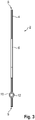
Fig. 3 in Frontansicht die Pouchzelle.
-
1 a perspective view of a pouch cell, -
2 a section of the pouch cell in a plan view, and -
3 the pouch cell in front view.
Einander entsprechende Teile und Größen sind in allen Figuren stets mit den gleichen Bezugszeichen versehen.Corresponding parts and sizes are always provided with the same reference symbols in all figures.
Die
Der Pouchbeutel 4 ist durch zwei umlaufend gefügte Beutelhälften gebildet. Die Beutelhälften sind hierbei als tiefgezogene Pouchfolien ausgeführt, welche beispielsweise als Aluminium-Verbundfolien oder als eine Aluminium-Laminatfolien ausgeführt sind. Die Beutelhälften sind hierbei umlaufend mittels einer als Siegelnaht ausgeführten Fügeverbindung 8 stoffschlüssig fluid- und druckdicht zu dem Pouchbeutel 4 gefügt.The
Wie insbesondere in den Darstellungen der
In dem Pouchbeutel 4 ist beispielsweise ein Flüssigelektrolyt aufgenommen, welcher den Elektrodenstapel durchsetzt. Der Entgasungskanal 10 ist hierbei an derjenigen Stirnseite angeordnet, welche in einer Einbausituation in der Fahrzeugbatterie dem Untergrund abgewandt ist. Mit anderen Worten ist der hierbei etwa vertikal ausgerichtete Entgasungskanal an einer Oberseite oder Oberkante der Pouchzelle 2 angeordnet.A liquid electrolyte, for example, which penetrates the electrode stack, is accommodated in the
Die Kanüle beziehungsweise der Entgasungskanal 10 weist beispielsweise eine kreisrunde Querschnittsform mit einem Durchmesser zwischen 2 mm bis 3 mm auf. Der Entgasungskanal 10 ist hierbei beispielsweise mittels eines Dicht- oder Klebemittels, insbesondere mittels eines Schmelzklebers, gegenüber dem Pouchbeutel 4 abgedichtet. Ebenso denkbar ist eine Ummantelung oder Beschichtung des Entgasungskanals 6 aus einem Kunststoffmaterial, welche mit dem Kunststoffmaterial der Pouchfolien gefügt wird. Weiterhin ist es denkbar, dass der Entgasungskanal 10 aus einem Kunststoffmaterial gefertigt ist, und unmittelbar stoffschlüssig mit dem Pouchbeutel 4 gefügt wird, wenn die Fügeverbindung 8 erzeugt wird.The cannula or the
Der Entgasungskanal 10 ist im Zuge eines Evakuierungsprozesses des Beutelinnenraums beispielswese offen, und wird nach dem Evakuierungsprozess fluid- und druckdicht mit dem Verschließelement 12 verschlossen. Der Entgasungskanal ist somit derart in den Pouchbeutel 4 beziehungsweise in die Fügeverbindung 8 eingebracht, dass die Pouchzelle 2 nach einer Formierung vakuumiert werden kann.The degassing
Ebenso möglich ist, dass der Entgasungskanal 10 auch während der Formierung und Vakuumierung mit dem Verschließelement 12 verschlossen ist. Insbesondere können eine Formierung und Gastasche des Pouchbeutels 4 derart ausgeführt werden, dass der Entgasungskanal 10 lediglich eingesiegelt wird, und der Formierungsdruck deutlich unter dem "Öffnungsdruck" liegt. Somit ist es möglich, alle Prozesse bei der Herstellung herkömmlich auszuführen, wodurch die Herstellungskosten reduziert werden.It is also possible that the degassing
Zwischen dem Verschließelement 12 und dem Entgasungskanal 10 ist eine Fügeverbindung, insbesondere eine stoffschlüssige Fügeverbindung, realisiert. Das Verschließelement 12 beziehungsweise die Fügeverbindung ist hierbei derart ausgelegt, dass das Verschließelement 12 bei einem hinreichend hohen Überdruck oder Innendruck des Beutelinnenraums selbsttätig oder automatisch aus dem Entgasungskanal 10 gedrückt oder gepresst, und somit der Entlüftungskanal 10 geöffnet oder freigegeben wird. In einer geeigneten Dimensionierung wird das Verschließelement 12 bei einem Überdruck zwischen 2 bar und 3 bar, insbesondere zwischen 2 bar und 2,5 bar, aus dem Entgasungskanal 10 herausgedrückt.A joint, in particular a material joint, is realized between the closing
Die beanspruchte Erfindung ist nicht auf die vorstehend beschriebenen Ausführungsbeispiele beschränkt. Vielmehr können auch andere Varianten der Erfindung von dem Fachmann hieraus im Rahmen der offenbarten Ansprüche abgeleitet werden, ohne den Gegenstand der beanspruchten Erfindung zu verlassen. Insbesondere sind ferner alle im Zusammenhang mit den verschiedenen Ausführungsbeispielen beschriebenen Einzelmerkmale im Rahmen der offenbarten Ansprüche auch auf andere Weise kombinierbar, ohne den Gegenstand der beanspruchten Erfindung zu verlassen.The claimed invention is not limited to the embodiments described above. Rather, other variants of the invention can also be derived from this by the person skilled in the art within the scope of the disclosed claims without departing from the subject matter of the claimed invention. In particular, all of the individual features described in connection with the various exemplary embodiments are also within the scope of those disclosed Claims can also be combined in other ways without departing from the subject matter of the claimed invention.
- 22
- Pouchzellepouch cell
- 44
- Pouchbeutelpouch bag
- 66
- Anschlusstabconnection tab
- 88th
- Fügeverbindungjoint connection
- 1010
- Entgasungskanaldegassing channel
- 1212
- Verschließelementclosing element
Claims (10)
dadurch gekennzeichnet,
characterized,
dadurch gekennzeichnet,
dass das Verschließelement (12) den Entgasungskanal (10) fluiddicht verschließt.Pouch cell (2) according to claim 1 or 2,
characterized,
that the closing element (12) closes the degassing channel (10) in a fluid-tight manner.
dadurch gekennzeichnet,
dass das Verschließelement (12) als eine plastische Masse in den Entgasungskanal (10) eingebracht ist.Pouch cell (2) according to one of claims 1 to 3,
characterized,
that the closing element (12) is introduced into the degassing channel (10) as a plastic mass.
dadurch gekennzeichnet,
dass der Entgasungskanal (10) im Zuge eines Evakuierungsprozesses des Beutelinnenraums offen ist, und nach dem Evakuierungsprozess fluiddicht mit dem Verschließelement (12) verschlossen ist.Pouch cell (2) according to one of claims 1 to 4,
characterized,
that the degassing channel (10) is open in the course of an evacuation process of the interior of the bag and is closed in a fluid-tight manner with the closure element (12) after the evacuation process.
dadurch gekennzeichnet,
dass der Entgasungskanal (10) als eine Kanüle ausgeführt ist.Pouch cell (2) according to any one of claims 1 to 5,
characterized,
that the degassing channel (10) is designed as a cannula.
dadurch gekennzeichnet,
dass der Entgasungskanal (10) aus einem Kunststoffmaterial hergestellt ist.Pouch cell (2) according to any one of claims 1 to 6,
characterized,
that the degassing channel (10) is made of a plastic material.
dadurch gekennzeichnet,
dass der Entgasungskanal (10) stoffschlüssig mit dem Material des Pouchbeutels (4) verbunden ist.Pouch cell (2) according to any one of claims 1 to 7,
characterized,
that the degassing channel (10) is materially connected to the material of the pouch bag (4).
dadurch gekennzeichnet,
dass das Verschließelement (12) derart ausgelegt ist, dass es bei einem Überdruck zwischen 2 bar und 3 bar aus dem Entgasungskanal (10) herausgedrückt wird.Pouch cell (2) according to any one of claims 1 to 8,
characterized,
that the closing element (12) is designed in such a way that it is pressed out of the degassing channel (10) at an overpressure of between 2 bar and 3 bar.
Applications Claiming Priority (1)
| Application Number | Priority Date | Filing Date | Title |
|---|---|---|---|
| DE102020216452.5A DE102020216452A1 (en) | 2020-12-22 | 2020-12-22 | pouch cell |
Publications (1)
| Publication Number | Publication Date |
|---|---|
| EP4020675A1 true EP4020675A1 (en) | 2022-06-29 |
Family
ID=78676373
Family Applications (1)
| Application Number | Title | Priority Date | Filing Date |
|---|---|---|---|
| EP21208556.7A Pending EP4020675A1 (en) | 2020-12-22 | 2021-11-16 | Pouch cell |
Country Status (4)
| Country | Link |
|---|---|
| EP (1) | EP4020675A1 (en) |
| KR (1) | KR20220090428A (en) |
| CN (1) | CN114665139A (en) |
| DE (1) | DE102020216452A1 (en) |
Families Citing this family (1)
| Publication number | Priority date | Publication date | Assignee | Title |
|---|---|---|---|---|
| DE102022209895A1 (en) | 2022-09-20 | 2024-03-21 | Volkswagen Aktiengesellschaft | Method for producing a battery pouch cell |
Citations (4)
| Publication number | Priority date | Publication date | Assignee | Title |
|---|---|---|---|---|
| EP2709191A1 (en) * | 2012-03-28 | 2014-03-19 | Optnics Precision Co., Ltd. | Safety valve and electrochemical element |
| DE102013219223A1 (en) | 2013-09-25 | 2015-03-26 | Robert Bosch Gmbh | Degassing valve for battery cells |
| JP2020063058A (en) * | 2018-10-15 | 2020-04-23 | 大日本印刷株式会社 | Valve and package with the same |
| KR20200103474A (en) * | 2019-02-25 | 2020-09-02 | 주식회사 엘지화학 | The Apparatus For Venting |
Family Cites Families (1)
| Publication number | Priority date | Publication date | Assignee | Title |
|---|---|---|---|---|
| DE102018127482A1 (en) | 2018-11-05 | 2020-05-07 | Sunrise Energy International GmbH | Safety device for softpack lithium titanate batteries |
-
2020
- 2020-12-22 DE DE102020216452.5A patent/DE102020216452A1/en active Pending
-
2021
- 2021-11-16 EP EP21208556.7A patent/EP4020675A1/en active Pending
- 2021-12-14 KR KR1020210178463A patent/KR20220090428A/en not_active Application Discontinuation
- 2021-12-22 CN CN202111577407.7A patent/CN114665139A/en active Pending
Patent Citations (4)
| Publication number | Priority date | Publication date | Assignee | Title |
|---|---|---|---|---|
| EP2709191A1 (en) * | 2012-03-28 | 2014-03-19 | Optnics Precision Co., Ltd. | Safety valve and electrochemical element |
| DE102013219223A1 (en) | 2013-09-25 | 2015-03-26 | Robert Bosch Gmbh | Degassing valve for battery cells |
| JP2020063058A (en) * | 2018-10-15 | 2020-04-23 | 大日本印刷株式会社 | Valve and package with the same |
| KR20200103474A (en) * | 2019-02-25 | 2020-09-02 | 주식회사 엘지화학 | The Apparatus For Venting |
Non-Patent Citations (1)
| Title |
|---|
| "Battery Pouch Cell Relief Valve With Fuse Plug", RESEARCH DISCLOSURE, KENNETH MASON PUBLICATIONS, HAMPSHIRE, UK, GB, vol. 628, no. 33, 1 August 2016 (2016-08-01), pages 611, XP007145007, ISSN: 0374-4353, [retrieved on 20160714] * |
Also Published As
| Publication number | Publication date |
|---|---|
| DE102020216452A1 (en) | 2022-06-23 |
| KR20220090428A (en) | 2022-06-29 |
| CN114665139A (en) | 2022-06-24 |
Similar Documents
| Publication | Publication Date | Title |
|---|---|---|
| EP2606520B1 (en) | Electrochemical cell having at least one pressure-relief device | |
| EP2448040A2 (en) | Magnetically sealing valve device for a battery casing | |
| DE102008059956A1 (en) | Battery i.e. lithium-ion-battery, for e.g. hybrid vehicle, has free space formed between cell bottom of single cells and battery housing bottom, where free space is pressure-tightly and/or gas-tightly separated in direction of single cells | |
| DE102012218188B4 (en) | Battery cell with cover plate fixed in the housing by gluing | |
| DE102009020185A1 (en) | Energy storage for hybrid vehicle, has safety device that is dimensioned to release closure of opening of battery case during exceeding pressure threshold value and/or temperature threshold value in battery case | |
| DE102011088636A1 (en) | Hard shell housing with superhydrophobic material | |
| DE102012018128A1 (en) | Single cell e.g. lithium ion cell, for use in elliptic column-type non-aqueous electrolyte battery for electric car, has electrode film arrangement pressed against wall of cell housing by elastic element that is designed as hollow body | |
| DE102012213110A1 (en) | Method for manufacturing film battery e.g. lithium ion battery mounted in vehicle, involves forming frame by casting around edge region of film stack, and opening casting tool after removal of a frame which is provided film stack | |
| DE112018006692T5 (en) | ENERGY STORAGE DEVICE | |
| DE102015014343A1 (en) | cell holder | |
| DE102013021331A1 (en) | battery | |
| EP4020675A1 (en) | Pouch cell | |
| DE102012018041A1 (en) | Isolation of electrochemical energy storage | |
| DE102014018751A1 (en) | Electrochemical energy storage and battery | |
| WO2022101062A1 (en) | Battery cell, housing of such a battery cell, battery having a multiplicity of such battery cells, and method for producing such a housing | |
| DE102013223361A1 (en) | Battery cell with safety valve and semi-permeable closure element | |
| WO2011051174A1 (en) | Battery cell having a gas reservoir | |
| EP2467886A1 (en) | Electrochemical cell | |
| WO2008098555A1 (en) | Fastening of energy storage cells in an enclosure | |
| DE102008059958B4 (en) | Single cell and battery with a plurality of electrically connected in series and / or parallel single cells | |
| DE102010055604A1 (en) | Bipolar flat cell for use in lithium-ion battery utilized as energy storage unit of electric drive assembly of e.g. hybrid vehicle, has opening, and shell bottom formed in region of recess corresponding to housing frame edge | |
| DE102010050046A1 (en) | Electrochemical cell and process for its preparation | |
| WO2012022453A1 (en) | Electrochemical cell having at least one pressure relief apparatus | |
| DE102013203106A1 (en) | Housing for battery cell e.g. lithium ion battery cell, has gastight and fluid-conductive connected channel portions that are arranged for forming degassing channel, and safety valve that is opened into channel portion | |
| DE102013016782A1 (en) | Single cell for a battery |
Legal Events
| Date | Code | Title | Description |
|---|---|---|---|
| PUAI | Public reference made under article 153(3) epc to a published international application that has entered the european phase |
Free format text: ORIGINAL CODE: 0009012 |
|
| STAA | Information on the status of an ep patent application or granted ep patent |
Free format text: STATUS: THE APPLICATION HAS BEEN PUBLISHED |
|
| AK | Designated contracting states |
Kind code of ref document: A1 Designated state(s): AL AT BE BG CH CY CZ DE DK EE ES FI FR GB GR HR HU IE IS IT LI LT LU LV MC MK MT NL NO PL PT RO RS SE SI SK SM TR |
|
| STAA | Information on the status of an ep patent application or granted ep patent |
Free format text: STATUS: REQUEST FOR EXAMINATION WAS MADE |
|
| 17P | Request for examination filed |
Effective date: 20230102 |
|
| RBV | Designated contracting states (corrected) |
Designated state(s): AL AT BE BG CH CY CZ DE DK EE ES FI FR GB GR HR HU IE IS IT LI LT LU LV MC MK MT NL NO PL PT RO RS SE SI SK SM TR |