EP4020405A1 - Road lane condition detection with lane assist for a vehicle using infrared detecting device - Google Patents
Road lane condition detection with lane assist for a vehicle using infrared detecting device Download PDFInfo
- Publication number
- EP4020405A1 EP4020405A1 EP21209749.7A EP21209749A EP4020405A1 EP 4020405 A1 EP4020405 A1 EP 4020405A1 EP 21209749 A EP21209749 A EP 21209749A EP 4020405 A1 EP4020405 A1 EP 4020405A1
- Authority
- EP
- European Patent Office
- Prior art keywords
- road
- detecting device
- vehicle
- infrared detecting
- heat
- Prior art date
- Legal status (The legal status is an assumption and is not a legal conclusion. Google has not performed a legal analysis and makes no representation as to the accuracy of the status listed.)
- Granted
Links
Images

Classifications
-
- G—PHYSICS
- G06—COMPUTING OR CALCULATING; COUNTING
- G06V—IMAGE OR VIDEO RECOGNITION OR UNDERSTANDING
- G06V20/00—Scenes; Scene-specific elements
- G06V20/50—Context or environment of the image
- G06V20/56—Context or environment of the image exterior to a vehicle by using sensors mounted on the vehicle
- G06V20/588—Recognition of the road, e.g. of lane markings; Recognition of the vehicle driving pattern in relation to the road
-
- G—PHYSICS
- G01—MEASURING; TESTING
- G01S—RADIO DIRECTION-FINDING; RADIO NAVIGATION; DETERMINING DISTANCE OR VELOCITY BY USE OF RADIO WAVES; LOCATING OR PRESENCE-DETECTING BY USE OF THE REFLECTION OR RERADIATION OF RADIO WAVES; ANALOGOUS ARRANGEMENTS USING OTHER WAVES
- G01S17/00—Systems using the reflection or reradiation of electromagnetic waves other than radio waves, e.g. lidar systems
- G01S17/88—Lidar systems specially adapted for specific applications
- G01S17/89—Lidar systems specially adapted for specific applications for mapping or imaging
-
- G—PHYSICS
- G01—MEASURING; TESTING
- G01S—RADIO DIRECTION-FINDING; RADIO NAVIGATION; DETERMINING DISTANCE OR VELOCITY BY USE OF RADIO WAVES; LOCATING OR PRESENCE-DETECTING BY USE OF THE REFLECTION OR RERADIATION OF RADIO WAVES; ANALOGOUS ARRANGEMENTS USING OTHER WAVES
- G01S17/00—Systems using the reflection or reradiation of electromagnetic waves other than radio waves, e.g. lidar systems
- G01S17/88—Lidar systems specially adapted for specific applications
- G01S17/93—Lidar systems specially adapted for specific applications for anti-collision purposes
- G01S17/931—Lidar systems specially adapted for specific applications for anti-collision purposes of land vehicles
-
- G—PHYSICS
- G01—MEASURING; TESTING
- G01S—RADIO DIRECTION-FINDING; RADIO NAVIGATION; DETERMINING DISTANCE OR VELOCITY BY USE OF RADIO WAVES; LOCATING OR PRESENCE-DETECTING BY USE OF THE REFLECTION OR RERADIATION OF RADIO WAVES; ANALOGOUS ARRANGEMENTS USING OTHER WAVES
- G01S7/00—Details of systems according to groups G01S13/00, G01S15/00, G01S17/00
- G01S7/48—Details of systems according to groups G01S13/00, G01S15/00, G01S17/00 of systems according to group G01S17/00
- G01S7/481—Constructional features, e.g. arrangements of optical elements
-
- H—ELECTRICITY
- H04—ELECTRIC COMMUNICATION TECHNIQUE
- H04N—PICTORIAL COMMUNICATION, e.g. TELEVISION
- H04N23/00—Cameras or camera modules comprising electronic image sensors; Control thereof
- H04N23/20—Cameras or camera modules comprising electronic image sensors; Control thereof for generating image signals from infrared radiation only
- H04N23/23—Cameras or camera modules comprising electronic image sensors; Control thereof for generating image signals from infrared radiation only from thermal infrared radiation
-
- G—PHYSICS
- G01—MEASURING; TESTING
- G01J—MEASUREMENT OF INTENSITY, VELOCITY, SPECTRAL CONTENT, POLARISATION, PHASE OR PULSE CHARACTERISTICS OF INFRARED, VISIBLE OR ULTRAVIOLET LIGHT; COLORIMETRY; RADIATION PYROMETRY
- G01J5/00—Radiation pyrometry, e.g. infrared or optical thermometry
- G01J2005/0077—Imaging
-
- G—PHYSICS
- G01—MEASURING; TESTING
- G01J—MEASUREMENT OF INTENSITY, VELOCITY, SPECTRAL CONTENT, POLARISATION, PHASE OR PULSE CHARACTERISTICS OF INFRARED, VISIBLE OR ULTRAVIOLET LIGHT; COLORIMETRY; RADIATION PYROMETRY
- G01J5/00—Radiation pyrometry, e.g. infrared or optical thermometry
- G01J5/02—Constructional details
- G01J5/08—Optical arrangements
- G01J5/0853—Optical arrangements having infrared absorbers other than the usual absorber layers deposited on infrared detectors like bolometers, wherein the heat propagation between the absorber and the detecting element occurs within a solid
-
- G—PHYSICS
- G06—COMPUTING OR CALCULATING; COUNTING
- G06T—IMAGE DATA PROCESSING OR GENERATION, IN GENERAL
- G06T2207/00—Indexing scheme for image analysis or image enhancement
- G06T2207/10—Image acquisition modality
- G06T2207/10048—Infrared image
Definitions
- This invention relates to Advanced Driver-Assistance Systems (ADAS) and, in particular, to a system that detects road lane conditions and provides vehicle lane assist using an infrared detecting device.
- ADAS Advanced Driver-Assistance Systems
- ADAS technology has come a long way over the years and has saved multiple lives in the process. However, such systems can be improved further, particularly during driving at night. Although there is significantly less traffic on the road at night (60 percent less), 40 percent of all fatal car accidents occur at night. Lane conditions at night are some of the hardest things to gauge as a driver.
- Patent Application Publication US2018/0141561 A1 discloses a system, having a conventional camera, for detecting and assessing reflections of light on a road to determine road conditions. However, such systems may have difficulty accessing road conditions at night when visible light is at a minimum.
- conventional lane assist systems for vehicles use conventional cameras to detect road lane markers typically painted on the road.
- these systems may be unable to be detect the lane markings.
- a system for a vehicle having a front, a rear, a right side and a left side.
- the system includes an infrared detecting device mounted on the front of the vehicle.
- the infrared detecting device is constructed and arranged to 1) detect variations in road temperature and 2) detect heat tracks left on a road lane by preceding vehicles.
- a control unit is mounted in the vehicle and is connected to the infrared detecting device so as to process signals received from the infrared detecting device.
- the control unit is constructed and arranged 1) to predict road conditions based on the variations in road temperature detected by the infrared detecting device or 2) to predict road lane location, based on a path defined by the heat tracks detected by the infrared detecting device.
- a method provides road condition data for a vehicle.
- the vehicle has a front, a rear, a right side and a left side.
- the method provides an infrared detecting device on the front of the vehicle. Variations in road temperature is detected with the infrared detecting device. Road conditions are predicted in a control unit based on the variations in road temperature detected by the infrared detecting device.
- a method of provides lane assist for a vehicle.
- the method provides an infrared detecting device on a front of the vehicle. Heat tracks left on a road lane by preceding vehicles are detected with the infrared detecting device. Road lane location is predicted by a control unit based on a path defined by the heat tracks detected by the infrared detecting device.
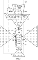
- an advanced driver assist or autonomous vehicle system is shown, generally indicated at 10, for a vehicle 12 in accordance with an embodiment.
- the system 10 includes an infrared measuring device 14, preferably mounted on the front 16 of the vehicle 12, such as on or in the grill or front bumper.
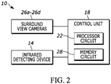
- the system also includes a control unit 18 mounted in the vehicle 12 and connected to the infrared detecting device 14 so as to process signals received from the infrared detecting device 14.
- the infrared detecting device's field of view (FOV) in front of the vehicle 10 is shown at 20.
- FOV field of view
- the infrared (IR) detecting device 14 comprises an infrared camera or a thermal imaging camera.
- the infrared camera typically uses short wavelength infrared light to illuminate an area of interest. Some of the infrared energy is reflected back to the infrared camera and interpreted to generate an image data.
- a thermal imaging camera typically uses mid or long wavelength infrared energy. Thermal imaging cameras are passive, and only sense differences in heat.
- the infrared detecting device 14 can detect variations in road temperature (heat signature) without the presence of light. This allows algorithms, executed by the processor circuit 22 of the control unit 18, to use this temperature variation data to determine predictions of road conditions. As shown in FIG.
- the infrared detecting device 14 can identify that there is water 24 on the road 25, based on the infrared data.
- the processor circuit 22 can execute an algorithm including the steps of receiving a heat signature of an object (e.g., water) on the road that has a heat signature different from a heat signature of surrounding areas on the road; comparing the received heat signal to known heat signals stored in a memory circuit 28; and predicting or identifying the type of object defining a road condition on the road based on the comparison.
- the output from the infrared road condition algorithm can then be compared to the output from the standard systems already present on the vehicle and these outputs can then be sent to the main computer system that is controlling the vehicle actuation for fusion.
- the data provided by the infrared detecting device 14 can be used in collaboration with the data from a conventional surround view camera system having a plurality of normal (non IR) cameras 26a-26d, each configure to obtain an image.
- First camera 26a is located on the front 16 of the vehicle 12
- second camera 26b is located on the rear 17 of the vehicle 12
- third camera 26c is located on the left side 19 of the vehicle 12
- fourth camera 26d is located on the right side 21 of the vehicle 12.
- These cameras 26a-26d are typically mono cameras having a FOV 27 of up to 125 degrees or fish-eye cameras having a FOV greater than 180 degrees, which can be used at least for lane assist, parking assist, and emergency braking for crash avoidance.
- Cameras 26a-26d are connected to the control unit 18.
- the cameras 26a-26d can also be used for road condition observance, as disclosed Patent Application Publication US2018/0141561 A1 , the content of which is hereby incorporated by refence herein.
- the light-reflective image capturing cameras 26a-26d can provide image data to the control unit 18 regarding road conditions when sufficient light is available, with the infrared detecting device 14 providing thermal data regarding road conditions to the control unit 18 when sufficient light is unavailable.
- the control unit 18 or other vehicle controller can control various vehicle systems (e.g., vehicle braking, speed control, etc.) depending on the sensed or predicted road conditions.
- Memory circuit 28 of the control unit 18 can store the algorithms and/or data from the infrared detecting device 14, and cameras 26a-26d.
- the infrared detecting device 14 can detect water, ice, or any lane irregularities much easier at night.
- the infrared detecting device 14 is able to determine road conditions based on variations in infrared readings across the road and these readings can then be compared to the output provided by the surround view cameras 26a-26d for improved accuracy.
- the control unit 18 can receive data other than from just the infrared detecting device 14 and/or the cameras 26a-26d, such as outside temperature, humidity, wind speed data, whether the vehicle wipers are on, etc. for use in predicting road conditions.
- the infrared detecting device 14 can be always on, or can be activated based on an ambient light sensors (e.g., the conventional light sensor that can automatically turn on the vehicle's lights as daylight fades)..
- the infrared detecting device 14 can be employed in a lane assist application by detecting heat tracks 30 on a road lane L left by another vehicle 30 or vehicles preceding the vehicle 12 traveling down the road 25.
- the heat from the tires of a vehicle 32 driving on the road creates a trail behind the vehicle 32.
- specific portions of the road lane L are warmer than others. High traffic and higher speed roads will provide better heat tracks 30 to follow.
- the processor circuit 22 of the control unit 18 can execute an algorithm to predict the road lane L location, based on the path most traveled by the other vehicles 32.
- the processor circuit 22 can execute an algorithm including the steps of receiving a heat signature of heat tracks 30 on the road that have a heat signature different from a heat signature of surrounding areas on the road; and calculating or predicting a lane location L on the road based on the location of the heat tracks 30. If the driver deviates from the lane L, the control unit 18 can activate a warning signal or can cause automatic control of the steering to bring the vehicle back into the lane.
- the output from the infrared lane assist algorithm can then be compared to the output from the standard systems already present on the vehicle and these outputs can then be sent to the main computer system that is controlling the vehicle actuation for fusion.
- the use of the infrared detecting device 14 reduces the need for quality lane markers 34 that are employed in conventional lane keeping technologies.
- the infrared detecting device 14 should be mounted to the front of the vehicle 12 as close to the road as possible. Infrared detecting device 14 can be used alone, or in conjunction with the surround view cameras 26a-26d of FIG. 1 that can provide data on the location of the lane markers 34.
- the infrared detecting device 14 can be used to enhance or as a backup to the regular lane marker detection system (e.g., mono-cameras) that is used for conventional lane assist.
- the infrared detecting device 14 can use the heat tracks 30 from other vehicles as a reference to where the lane L should be.
- the operations and algorithms described herein can be implemented as executable code within a micro-controller or control unit 18 having processor circuit 22 as described, or stored on a standalone computer or machine readable non-transitory tangible storage medium that are completed based on execution of the code by a processor circuit implemented using one or more integrated circuits.
- Example implementations of the disclosed circuits include hardware logic that is implemented in a logic array such as a programmable logic array (PLA), a field programmable gate array (FPGA), or by mask programming of integrated circuits such as an application-specific integrated circuit (ASIC).
- PLA programmable logic array
- FPGA field programmable gate array
- ASIC application-specific integrated circuit
- any of these circuits also can be implemented using a software-based executable resource that is executed by a corresponding internal processor circuit such as a micro-processor circuit (not shown) and implemented using one or more integrated circuits, where execution of executable code stored in an internal memory circuit causes the integrated circuit(s) implementing the processor circuit to store application state variables in processor memory, creating an executable application resource (e.g., an application instance) that performs the operations of the circuit as described herein.
- a software-based executable resource that is executed by a corresponding internal processor circuit such as a micro-processor circuit (not shown) and implemented using one or more integrated circuits, where execution of executable code stored in an internal memory circuit causes the integrated circuit(s) implementing the processor circuit to store application state variables in processor memory, creating an executable application resource (e.g., an application instance) that performs the operations of the circuit as described herein.
- a software-based executable resource that is executed by a corresponding internal processor circuit such as a micro-processor circuit (not shown)
- circuit refers to both a hardware-based circuit implemented using one or more integrated circuits and that includes logic for performing the described operations, or a software-based circuit that includes a processor circuit (implemented using one or more integrated circuits), the processor circuit including a reserved portion of processor memory for storage of application state data and application variables that are modified by execution of the executable code by a processor circuit.
- the memory circuit 28 can be implemented, for example, using a non-volatile memory such as a programmable read only memory (PROM) or an EPROM, and/or a volatile memory such as a DRAM, etc.
Landscapes
- Engineering & Computer Science (AREA)
- Physics & Mathematics (AREA)
- General Physics & Mathematics (AREA)
- Multimedia (AREA)
- Computer Networks & Wireless Communication (AREA)
- Radar, Positioning & Navigation (AREA)
- Remote Sensing (AREA)
- Electromagnetism (AREA)
- Signal Processing (AREA)
- Health & Medical Sciences (AREA)
- Toxicology (AREA)
- Theoretical Computer Science (AREA)
- Traffic Control Systems (AREA)
- Control Of Driving Devices And Active Controlling Of Vehicle (AREA)
Abstract
Description
- This invention relates to Advanced Driver-Assistance Systems (ADAS) and, in particular, to a system that detects road lane conditions and provides vehicle lane assist using an infrared detecting device.
- ADAS technology has come a long way over the years and has saved multiple lives in the process. However, such systems can be improved further, particularly during driving at night. Although there is significantly less traffic on the road at night (60 percent less), 40 percent of all fatal car accidents occur at night. Lane conditions at night are some of the hardest things to gauge as a driver. Patent Application Publication
US2018/0141561 A1 discloses a system, having a conventional camera, for detecting and assessing reflections of light on a road to determine road conditions. However, such systems may have difficulty accessing road conditions at night when visible light is at a minimum. - Furthermore, conventional lane assist systems for vehicles use conventional cameras to detect road lane markers typically painted on the road. However, during night driving with poor lighting, or when the lane markings lack sufficient paint, these systems may be unable to be detect the lane markings.
- Thus, there is a need to provide an improved ADAS system using an infrared detecting device to detect road conditions and that can aid in the lane assist function.
- An objective of the invention is to fulfill the need referred to above. In accordance with the principles of an embodiment, this objective is achieved by a system for a vehicle having a front, a rear, a right side and a left side. The system includes an infrared detecting device mounted on the front of the vehicle. The infrared detecting device is constructed and arranged to 1) detect variations in road temperature and 2) detect heat tracks left on a road lane by preceding vehicles. A control unit is mounted in the vehicle and is connected to the infrared detecting device so as to process signals received from the infrared detecting device. The control unit is constructed and arranged 1) to predict road conditions based on the variations in road temperature detected by the infrared detecting device or 2) to predict road lane location, based on a path defined by the heat tracks detected by the infrared detecting device.
- In accordance with another aspect of an embodiment, a method provides road condition data for a vehicle. The vehicle has a front, a rear, a right side and a left side. The method provides an infrared detecting device on the front of the vehicle. Variations in road temperature is detected with the infrared detecting device. Road conditions are predicted in a control unit based on the variations in road temperature detected by the infrared detecting device.
- In accordance with yet another aspect of an embodiment, a method of provides lane assist for a vehicle. The method provides an infrared detecting device on a front of the vehicle. Heat tracks left on a road lane by preceding vehicles are detected with the infrared detecting device. Road lane location is predicted by a control unit based on a path defined by the heat tracks detected by the infrared detecting device.
- Other objectives, features and characteristics of the present invention, as well as the methods of operation and the functions of the related elements of the structure, the combination of parts and economics of manufacture will become more apparent upon consideration of the following detailed description and appended claims with reference to the accompanying drawings, all of which form a part of this specification.
- The invention will be better understood from the following detailed description of the preferred embodiments thereof, taken in conjunction with the accompanying drawings, wherein like reference numerals refer to like parts, in which:
-
FIG. 1 is a plan view of a vehicle equipped with an advanced driver assist or autonomous vehicle system for determining road condition in accordance with an embodiment of the invention. -
FIG. 2 is a schematic view of the system ofFIG. 1 . -
FIG. 3 is a plan view of a vehicle equipped with an advanced driver assist or autonomous vehicle system for lane assist in accordance with another aspect of the invention. - With reference to
FIG. 1 , an advanced driver assist or autonomous vehicle system is shown, generally indicated at 10, for avehicle 12 in accordance with an embodiment. Thesystem 10 includes aninfrared measuring device 14, preferably mounted on thefront 16 of thevehicle 12, such as on or in the grill or front bumper. As best shown inFIG. 2 , the system also includes acontrol unit 18 mounted in thevehicle 12 and connected to theinfrared detecting device 14 so as to process signals received from theinfrared detecting device 14. The infrared detecting device's field of view (FOV) in front of thevehicle 10 is shown at 20. - In the embodiment, the infrared (IR) detecting
device 14 comprises an infrared camera or a thermal imaging camera. The infrared camera typically uses short wavelength infrared light to illuminate an area of interest. Some of the infrared energy is reflected back to the infrared camera and interpreted to generate an image data. A thermal imaging camera typically uses mid or long wavelength infrared energy. Thermal imaging cameras are passive, and only sense differences in heat. Thus, theinfrared detecting device 14 can detect variations in road temperature (heat signature) without the presence of light. This allows algorithms, executed by theprocessor circuit 22 of thecontrol unit 18, to use this temperature variation data to determine predictions of road conditions. As shown inFIG. 1 , for example, theinfrared detecting device 14 can identify that there iswater 24 on theroad 25, based on the infrared data. Thus, for example, theprocessor circuit 22 can execute an algorithm including the steps of receiving a heat signature of an object (e.g., water) on the road that has a heat signature different from a heat signature of surrounding areas on the road; comparing the received heat signal to known heat signals stored in amemory circuit 28; and predicting or identifying the type of object defining a road condition on the road based on the comparison. The output from the infrared road condition algorithm can then be compared to the output from the standard systems already present on the vehicle and these outputs can then be sent to the main computer system that is controlling the vehicle actuation for fusion. - The data provided by the
infrared detecting device 14 can be used in collaboration with the data from a conventional surround view camera system having a plurality of normal (non IR)cameras 26a-26d, each configure to obtain an image.First camera 26a is located on thefront 16 of thevehicle 12,second camera 26b is located on the rear 17 of thevehicle 12,third camera 26c is located on theleft side 19 of thevehicle 12 andfourth camera 26d is located on theright side 21 of thevehicle 12. Thesecameras 26a-26d are typically mono cameras having aFOV 27 of up to 125 degrees or fish-eye cameras having a FOV greater than 180 degrees, which can be used at least for lane assist, parking assist, and emergency braking for crash avoidance.Cameras 26a-26d are connected to thecontrol unit 18. Certain of thecameras 26a-26d can also be used for road condition observance, as disclosed Patent Application PublicationUS2018/0141561 A1 , the content of which is hereby incorporated by refence herein. Thus, the light-reflectiveimage capturing cameras 26a-26d, can provide image data to thecontrol unit 18 regarding road conditions when sufficient light is available, with theinfrared detecting device 14 providing thermal data regarding road conditions to thecontrol unit 18 when sufficient light is unavailable. With such data, thecontrol unit 18 or other vehicle controller can control various vehicle systems (e.g., vehicle braking, speed control, etc.) depending on the sensed or predicted road conditions.Memory circuit 28 of thecontrol unit 18 can store the algorithms and/or data from theinfrared detecting device 14, andcameras 26a-26d. - Thus, the
infrared detecting device 14 can detect water, ice, or any lane irregularities much easier at night. Theinfrared detecting device 14 is able to determine road conditions based on variations in infrared readings across the road and these readings can then be compared to the output provided by thesurround view cameras 26a-26d for improved accuracy. It can be appreciated that thecontrol unit 18 can receive data other than from just theinfrared detecting device 14 and/or thecameras 26a-26d, such as outside temperature, humidity, wind speed data, whether the vehicle wipers are on, etc. for use in predicting road conditions. Also, theinfrared detecting device 14 can be always on, or can be activated based on an ambient light sensors (e.g., the conventional light sensor that can automatically turn on the vehicle's lights as daylight fades).. - With reference to
FIG. 3 , theinfrared detecting device 14 can be employed in a lane assist application by detectingheat tracks 30 on a road lane L left by anothervehicle 30 or vehicles preceding thevehicle 12 traveling down theroad 25. The heat from the tires of avehicle 32 driving on the road creates a trail behind thevehicle 32. With multiple vehicles driving in the same road lane L, specific portions of the road lane L are warmer than others. High traffic and higher speed roads will providebetter heat tracks 30 to follow. - The
processor circuit 22 of thecontrol unit 18 can execute an algorithm to predict the road lane L location, based on the path most traveled by theother vehicles 32. For example, theprocessor circuit 22 can execute an algorithm including the steps of receiving a heat signature of heat tracks 30 on the road that have a heat signature different from a heat signature of surrounding areas on the road; and calculating or predicting a lane location L on the road based on the location of the heat tracks 30. If the driver deviates from the lane L, thecontrol unit 18 can activate a warning signal or can cause automatic control of the steering to bring the vehicle back into the lane. Alternatively, the output from the infrared lane assist algorithm can then be compared to the output from the standard systems already present on the vehicle and these outputs can then be sent to the main computer system that is controlling the vehicle actuation for fusion. - The use of the infrared detecting
device 14 reduces the need forquality lane markers 34 that are employed in conventional lane keeping technologies. The infrared detectingdevice 14 should be mounted to the front of thevehicle 12 as close to the road as possible. Infrared detectingdevice 14 can be used alone, or in conjunction with thesurround view cameras 26a-26d ofFIG. 1 that can provide data on the location of thelane markers 34. Thus, the infrared detectingdevice 14 can be used to enhance or as a backup to the regular lane marker detection system (e.g., mono-cameras) that is used for conventional lane assist. Whenlane markers 34 are unable to be detected by certain of themono cameras 26a-26d due to poor lighting or lack of paint, the infrared detectingdevice 14 can use the heat tracks 30 from other vehicles as a reference to where the lane L should be. - The operations and algorithms described herein can be implemented as executable code within a micro-controller or
control unit 18 havingprocessor circuit 22 as described, or stored on a standalone computer or machine readable non-transitory tangible storage medium that are completed based on execution of the code by a processor circuit implemented using one or more integrated circuits. Example implementations of the disclosed circuits include hardware logic that is implemented in a logic array such as a programmable logic array (PLA), a field programmable gate array (FPGA), or by mask programming of integrated circuits such as an application-specific integrated circuit (ASIC). Any of these circuits also can be implemented using a software-based executable resource that is executed by a corresponding internal processor circuit such as a micro-processor circuit (not shown) and implemented using one or more integrated circuits, where execution of executable code stored in an internal memory circuit causes the integrated circuit(s) implementing the processor circuit to store application state variables in processor memory, creating an executable application resource (e.g., an application instance) that performs the operations of the circuit as described herein. Hence, use of the term "circuit" in this specification refers to both a hardware-based circuit implemented using one or more integrated circuits and that includes logic for performing the described operations, or a software-based circuit that includes a processor circuit (implemented using one or more integrated circuits), the processor circuit including a reserved portion of processor memory for storage of application state data and application variables that are modified by execution of the executable code by a processor circuit. Thememory circuit 28 can be implemented, for example, using a non-volatile memory such as a programmable read only memory (PROM) or an EPROM, and/or a volatile memory such as a DRAM, etc. - The foregoing preferred embodiments have been shown and described for the purposes of illustrating the structural and functional principles of the present invention, as well as illustrating the methods of employing the preferred embodiments and are subject to change without departing from such principles. Therefore, this invention includes all modifications encompassed within the scope of the following claims.
- Further Embodiments:
- 1. A system for a vehicle, the vehicle having a front, a rear, a right side and a left side, the system comprising:
- an infrared detecting device mounted on the front of the vehicle, the infrared detecting device being constructed and arranged to 1) detect variations in road temperature and 2) detect heat tracks left on a road lane by preceding vehicles, and
- control unit mounted in the vehicle and connected to the infrared detecting device so as to process signals received from the infrared detecting device, the control unit being constructed and arranged 1) to predict road conditions based on the variations in road temperature detected by the infrared detecting device or 2) to predict road lane location, based on a path defined by the heat tracks detected by the infrared detecting device.
- 2. The system of embodiment 1, wherein the infrared detecting device is an infrared camera.
- 3. The system of embodiment 1, wherein the infrared detecting device is a thermal imaging camera.
- 4. The system of embodiment 1, wherein the control unit includes a processor circuit constructed and arranged to execute algorithms to predict the road conditions or to predict the road lane location.
- 5. The system of embodiment 4, wherein the processor circuit is constructed and arranged to execute the algorithm including the steps of receiving a heat signature of an object on the road that has a heat signature different from a heat signature of surrounding areas on the road; comparing the received heat signal to known heat signals stored in a memory circuit; and predicting or identifying the type of object defining a road condition on the road based on the comparison.
- 6. The system of embodiment 4, the
processor circuit 22 is constructed and arranged to execute an algorithm including the steps of receiving a heat signature of heat tracks on the road that have a heat signature different from a heat signature of surrounding areas on the road, and calculating or predicting a lane location on the road based on the location of the heat tracks. - 7. The system of embodiment 1, further comprising:
- a first camera mounted on the front of the vehicle,
- a second camera mounted on the rear of the vehicle,
- a third camera mounted on the left side of the vehicle, and
- a fourth camera mounted on the right side of the vehicle,
- wherein the first, second, third and fourth cameras define image capturing cameras and are each connected with the control unit such that the infrared detecting device in conjunction with certain of the image capturing cameras can 1) provide image data to the control unit regarding road conditions when sufficient light is available, and the infrared detecting device can provide thermal data to the control unit regarding road conditions when sufficient light is unavailable, or 2) to provide lane assist data based on the detected heat tracks alone or in conjunction with image data from the cameras.
- 8. The system of embodiment 7, wherein each of first, second, third and fourth camera is a mono camera having a field of view of up to 125 degrees.
- 9. The system of embodiment 7, wherein each of first, second, third and fourth camera is a fish-eye camera having a field of view greater than 180 degrees.
- 10. The system of embodiment 7, wherein certain of the first, second, third and fourth cameras are configured to detect road lane markers.
- 11. The system of embodiment 7, wherein certain of the first, second, third and fourth cameras are configured to detect reflection of light on the road.
- 12. A method of providing road condition data for a vehicle, the vehicle having a front, a rear, a right side and a left side, the method comprising:
- providing an infrared detecting device on the front of the vehicle, detecting, with the infrared detecting device, variations in road temperature, and
- predicting, in a control unit, road conditions based on the variations in road temperature detected by the infrared detecting device.
- 13. The method of
embodiment 12, wherein the infrared detecting device is provided as an infrared camera. - 14. The method of
embodiment 12, wherein the infrared detecting device is provided as a thermal imaging camera. - 15. The method of
embodiment 12, wherein the control unit includes a processor circuit and the method further comprises:- executing, via the processor circuit, an algorithm to predict the road conditions by receiving a heat signature of an object on the road that has a heat signature different from a heat signature of surrounding areas on the road; comparing the received heat signal to known heat signals stored in a memory circuit; and
- predicting or identifying the type of object defining a road condition on the road based on the comparison.
- 16. The method of
embodiment 12, further comprising:- providing a first camera mounted on the front of the vehicle,
- providing a second camera mounted on the rear of the vehicle,
- providing a third camera mounted on the left side of the vehicle,
- providing a fourth camera mounted on the right side of the vehicle,
- wherein the first, second, third and fourth cameras define image capturing cameras and are each connected with the control unit,
- providing, via certain of the image capturing cameras, image data to the control unit regarding road conditions when sufficient light is available, and
- providing, with the infrared detecting device, thermal data to the control unit regarding road conditions when sufficient light is unavailable.
- 17. A method of providing lane assist for a vehicle, the vehicle having a front, a rear, a right side and a left side, the method comprising:
- providing an infrared detecting device on the front of the vehicle, detecting, with the infrared detecting device, heat tracks left on a road lane by preceding vehicles, and
- predicting, in a control unit, road lane location, based on a path defined by the heat tracks detected by the infrared detecting device.
- 18. The method of
embodiment 17, wherein the infrared detecting device is provided as an infrared camera. - 19. The method of
embodiment 17, wherein the infrared detecting device is provided as a thermal imaging camera. - 20. The method of
embodiment 17, wherein the control unit includes a processor circuit and the method further comprises:
executing, via the processor circuit, an algorithm to receiving a heat signature of the heat tracks on the road that have a heat signature different from a heat signature of surrounding areas on the road, and calculating or predicting a lane location on the road based on the location of the heat tracks.
Claims (15)
- A system for a vehicle, the vehicle having a front, a rear, a right side and a left side, the system comprising:an infrared detecting device mounted on the front of the vehicle, the infrared detecting device being constructed and arranged to 1) detect variations in road temperature and 2) detect heat tracks left on a road lane by preceding vehicles, andcontrol unit mounted in the vehicle and connected to the infrared detecting device so as to process signals received from the infrared detecting device, the control unit being constructed and arranged 1) to predict road conditions based on the variations in road temperature detected by the infrared detecting device or 2) to predict road lane location, based on a path defined by the heat tracks detected by the infrared detecting device.
- The system of claim 1, wherein the infrared detecting device is an infrared camera or a thermal imaging camera.
- The system according to any of the preceding claims, wherein the control unit includes a processor circuit constructed and arranged to execute algorithms to predict the road conditions or to predict the road lane location.
- The system of claim 3, wherein the processor circuit (22) is constructed and arranged to execute the algorithm including the steps of receiving a heat signature of an object on the road that has a heat signature different from a heat signature of surrounding areas on the road; comparing the received heat signal to known heat signals stored in a memory circuit; and predicting or identifying the type of object defining a road condition on the road based on the comparison.
- The system of claim 3 or 4, wherein the processor circuit (22) is constructed and arranged to execute an algorithm including the steps of receiving a heat signature of heat tracks on the road that have a heat signature different from a heat signature of surrounding areas on the road, and calculating or predicting a lane location on the road based on the location of the heat tracks.
- The system according to any of the preceding claims, further comprising:a first camera mounted on the front of the vehicle,a second camera mounted on the rear of the vehicle,a third camera mounted on the left side of the vehicle, anda fourth camera mounted on the right side of the vehicle,wherein the first, second, third and fourth cameras define image capturing cameras and are each connected with the control unit such that the infrared detecting device in conjunction with certain of the image capturing cameras can 1) provide image data to the control unit regarding road conditions when sufficient light is available, and the infrared detecting device can provide thermal data to the control unit regarding road conditions when sufficient light is unavailable, or 2) to provide lane assist data based on the detected heat tracks alone or in conjunction with image data from the cameras.
- The system of claim 6, wherein each of first, second, third and fourth camera is a mono camera having a field of view of up to 125 degrees or a fish-eye camera having a field of view greater than 180 degrees.
- The system of claim 6 or 7, wherein certain of the first, second, third and fourth cameras are configured to detect road lane markers or reflection of light on the road.
- A method of providing road condition data for a vehicle, in particular by employing a system according to any of the claims 1 to 8,the vehicle having a front, a rear, a right side and a left side, the method comprising:providing an infrared detecting device on the front of the vehicle,detecting, with the infrared detecting device, variations in road temperature,
andpredicting, in a control unit, road conditions based on the variations in road temperature detected by the infrared detecting device. - The method of claim 9, wherein the infrared detecting device is provided as an infrared camera or as a thermal imaging camera.
- The method of claim 9 or 10, wherein the control unit includes a processor circuit and the method further comprises:
executing, via the processor circuit, an algorithm to predict the road conditions by receiving a heat signature of an object on the road that has a heat signature different from a heat signature of surrounding areas on the road; comparing the received heat signal to known heat signals stored in a memory circuit; and predicting or identifying the type of object defining a road condition on the road based on the comparison. - The method according to any of the claims 9 to 11, further comprising:providing a first camera mounted on the front of the vehicle,providing a second camera mounted on the rear of the vehicle,providing a third camera mounted on the left side of the vehicle,providing a fourth camera mounted on the right side of the vehicle,wherein the first, second, third and fourth cameras define image capturing cameras and are each connected with the control unit,providing, via certain of the image capturing cameras, image data to the control unit regarding road conditions when sufficient light is available, andproviding, with the infrared detecting device, thermal data to the control unit regarding road conditions when sufficient light is unavailable.
- A method of providing lane assist for a vehicle, in particular by employing a system according to any of the claims 1 to 8, the vehicle having a front, a rear, a right side and a left side, the method comprising:providing an infrared detecting device on the front of the vehicle, detecting, with the infrared detecting device, heat tracks left on a road lane by preceding vehicles, andpredicting, in a control unit, road lane location, based on a path defined by the heat tracks detected by the infrared detecting device.
- The method of claim 13, wherein the infrared detecting device is provided as an infrared camera or as a thermal imaging camera.
- The method of claim 13 or 14, wherein the control unit includes a processor circuit and the method further comprises:
executing, via the processor circuit, an algorithm to receiving a heat signature of the heat tracks on the road that have a heat signature different from a heat signature of surrounding areas on the road, and calculating or predicting a lane location on the road based on the location of the heat tracks.
Applications Claiming Priority (1)
| Application Number | Priority Date | Filing Date | Title |
|---|---|---|---|
| US17/247,751 US20220198200A1 (en) | 2020-12-22 | 2020-12-22 | Road lane condition detection with lane assist for a vehicle using infrared detecting device |
Publications (2)
| Publication Number | Publication Date |
|---|---|
| EP4020405A1 true EP4020405A1 (en) | 2022-06-29 |
| EP4020405B1 EP4020405B1 (en) | 2026-03-18 |
Family
ID=78770389
Family Applications (1)
| Application Number | Title | Priority Date | Filing Date |
|---|---|---|---|
| EP21209749.7A Active EP4020405B1 (en) | 2020-12-22 | 2021-11-23 | Road lane condition detection with lane assist for a vehicle using infrared detecting device |
Country Status (3)
| Country | Link |
|---|---|
| US (1) | US20220198200A1 (en) |
| EP (1) | EP4020405B1 (en) |
| JP (1) | JP7604357B2 (en) |
Families Citing this family (5)
| Publication number | Priority date | Publication date | Assignee | Title |
|---|---|---|---|---|
| US20210215798A1 (en) * | 2020-01-10 | 2021-07-15 | Continental Automotive Systems, Inc. | Lidar system |
| US12037757B2 (en) | 2021-03-04 | 2024-07-16 | Nec Corporation Of America | Infrared retroreflective spheres for enhanced road marks |
| US12104911B2 (en) * | 2021-03-04 | 2024-10-01 | Nec Corporation Of America | Imperceptible road markings to support automated vehicular systems |
| US12002270B2 (en) | 2021-03-04 | 2024-06-04 | Nec Corporation Of America | Enhanced detection using special road coloring |
| US20230286500A1 (en) * | 2022-03-11 | 2023-09-14 | Fusion Processing Limited | System for monitoring a position of a vehicle |
Citations (4)
| Publication number | Priority date | Publication date | Assignee | Title |
|---|---|---|---|---|
| US20180134281A1 (en) * | 2016-11-16 | 2018-05-17 | NextEv USA, Inc. | System for controlling a vehicle based on thermal profile tracking |
| US20180141561A1 (en) | 2015-05-06 | 2018-05-24 | Continental Teves Ag & Co. Ohg | Method and Apparatus for Detecting and Assessing Road Reflections |
| WO2019195404A1 (en) * | 2018-04-03 | 2019-10-10 | Mobileye Vision Technologies Ltd. | Systems and methods for vehicle navigation |
| US20200249681A1 (en) * | 2018-05-11 | 2020-08-06 | Arnold Chase | Passive infra-red guidance system |
Family Cites Families (33)
| Publication number | Priority date | Publication date | Assignee | Title |
|---|---|---|---|---|
| US20150235094A1 (en) * | 2014-02-17 | 2015-08-20 | General Electric Company | Vehicle imaging system and method |
| US20150269722A1 (en) * | 2014-03-18 | 2015-09-24 | General Electric Company | Optical route examination system and method |
| US20070035625A9 (en) * | 2002-12-20 | 2007-02-15 | Hamdan Majed M | Vehicle video processing system |
| US7463281B2 (en) * | 2003-08-06 | 2008-12-09 | Microsoft Corporation | Smart vehicle video management |
| JP2007036831A (en) * | 2005-07-28 | 2007-02-08 | Sumitomo Electric Ind Ltd | Image display system, image display method, and imaging apparatus |
| NL1030678C1 (en) * | 2005-12-15 | 2006-02-06 | Internova Holding Bvba | Camera system. |
| WO2008043795A1 (en) * | 2006-10-13 | 2008-04-17 | Continental Teves Ag & Co. Ohg | Method and apparatus for identifying concealed objects in road traffic |
| JP2008302746A (en) | 2007-06-05 | 2008-12-18 | Fujitsu Ten Ltd | Vehicle control device and vehicle control method |
| DE102007042481B4 (en) * | 2007-09-06 | 2022-04-07 | Zf Cv Systems Hannover Gmbh | Vehicle control system for an automobile |
| US9921584B2 (en) * | 2014-04-03 | 2018-03-20 | General Electric Company | Route examination system and method |
| WO2015157410A1 (en) * | 2014-04-08 | 2015-10-15 | Tk Holdings Inc. | System and method for night vision object detection and driver assistance |
| US9475491B1 (en) * | 2015-06-08 | 2016-10-25 | Toyota Motor Engineering & Manufacturing North America, Inc. | Lane changing for autonomous vehicles |
| WO2017020142A1 (en) * | 2015-08-03 | 2017-02-09 | 深圳市好航科技有限公司 | Multi-purpose vehicle smart monitoring system and method |
| CN105599765A (en) * | 2015-12-11 | 2016-05-25 | 上海卓易科技股份有限公司 | Lane departure judging and early warning method |
| SE541041C2 (en) * | 2016-02-24 | 2019-03-19 | Scania Cv Ab | Method and system for controlling a vehicle on a road with wheel grooves |
| US9760806B1 (en) * | 2016-05-11 | 2017-09-12 | TCL Research America Inc. | Method and system for vision-centric deep-learning-based road situation analysis |
| US10339391B2 (en) * | 2016-08-24 | 2019-07-02 | Gm Global Technology Operations Llc. | Fusion-based wet road surface detection |
| US20180075308A1 (en) * | 2016-09-14 | 2018-03-15 | GM Global Technology Operations LLC | Methods And Systems For Adaptive On-Demand Infrared Lane Detection |
| WO2018049678A1 (en) * | 2016-09-19 | 2018-03-22 | 华为技术有限公司 | Base, mobile terminal, headphone, and headphone base |
| KR20180090610A (en) * | 2017-02-03 | 2018-08-13 | 삼성전자주식회사 | Method and apparatus for outputting information about a lane |
| US10445928B2 (en) * | 2017-02-11 | 2019-10-15 | Vayavision Ltd. | Method and system for generating multidimensional maps of a scene using a plurality of sensors of various types |
| JP7136106B2 (en) * | 2017-08-18 | 2022-09-13 | ソニーグループ株式会社 | VEHICLE DRIVING CONTROL DEVICE, VEHICLE DRIVING CONTROL METHOD, AND PROGRAM |
| US10467903B1 (en) * | 2018-05-11 | 2019-11-05 | Arnold Chase | Passive infra-red pedestrian detection and avoidance system |
| FR3082812B1 (en) * | 2018-06-20 | 2020-09-11 | Psa Automobiles Sa | METHOD AND SYSTEM FOR MANAGING A CHANGE OF TRACK OF AN AUTONOMOUS OR PARTLY AUTONOMOUS VEHICLE |
| CN109383371A (en) * | 2018-09-19 | 2019-02-26 | 行为科技(北京)有限公司 | A kind of ADAS product driveway deviation alarming system |
| EP3627378A1 (en) * | 2018-09-19 | 2020-03-25 | Conti Temic microelectronic GmbH | Enhancing the detection of non-structured objects on a driveway |
| CN109709961B (en) * | 2018-12-28 | 2021-12-07 | 百度在线网络技术(北京)有限公司 | Road obstacle detection method and device and automatic driving automobile |
| KR102061445B1 (en) * | 2019-02-22 | 2019-12-31 | 써모아이 주식회사 | Method and apparatus for object recognition based on visible light and infrared fusion image |
| SG11202108455PA (en) * | 2019-02-28 | 2021-09-29 | Shenzhen Sensetime Technology Co Ltd | Vehicle intelligent driving control method and apparatus, electronic device and storage medium |
| US11077846B2 (en) * | 2019-03-31 | 2021-08-03 | Gm Cruise Holdings Llc | Controlling an autonomous vehicle based upon a predicted imminent lane change |
| US12399015B2 (en) * | 2019-04-12 | 2025-08-26 | Nvidia Corporation | Neural network training using ground truth data augmented with map information for autonomous machine applications |
| US11453410B2 (en) * | 2019-11-18 | 2022-09-27 | Hitachi, Ltd. | Reducing processing requirements for vehicle control |
| US11303827B2 (en) * | 2020-04-27 | 2022-04-12 | Samsung Electronics Co., Ltd. | Optical device for a thermal sensor and a hybrid thermal sensor |
-
2020
- 2020-12-22 US US17/247,751 patent/US20220198200A1/en not_active Abandoned
-
2021
- 2021-11-23 EP EP21209749.7A patent/EP4020405B1/en active Active
- 2021-12-21 JP JP2021206788A patent/JP7604357B2/en active Active
Patent Citations (4)
| Publication number | Priority date | Publication date | Assignee | Title |
|---|---|---|---|---|
| US20180141561A1 (en) | 2015-05-06 | 2018-05-24 | Continental Teves Ag & Co. Ohg | Method and Apparatus for Detecting and Assessing Road Reflections |
| US20180134281A1 (en) * | 2016-11-16 | 2018-05-17 | NextEv USA, Inc. | System for controlling a vehicle based on thermal profile tracking |
| WO2019195404A1 (en) * | 2018-04-03 | 2019-10-10 | Mobileye Vision Technologies Ltd. | Systems and methods for vehicle navigation |
| US20200249681A1 (en) * | 2018-05-11 | 2020-08-06 | Arnold Chase | Passive infra-red guidance system |
Also Published As
| Publication number | Publication date |
|---|---|
| EP4020405B1 (en) | 2026-03-18 |
| JP7604357B2 (en) | 2024-12-23 |
| US20220198200A1 (en) | 2022-06-23 |
| JP2022099309A (en) | 2022-07-04 |
Similar Documents
| Publication | Publication Date | Title |
|---|---|---|
| US20220198200A1 (en) | Road lane condition detection with lane assist for a vehicle using infrared detecting device | |
| EP2922033B1 (en) | A vehicle sensor diagnosis system and method and a vehicle comprising such a system | |
| US8396655B2 (en) | Motor vehicle control system | |
| CN113119963B (en) | Intelligent ultrasonic system, vehicle rear collision warning device and control method thereof | |
| US10140531B2 (en) | Detection of brake lights of preceding vehicles for adaptation of an initiation of active safety mechanisms | |
| CN108137054B (en) | Replacement of sensor measurement data | |
| EP3366539B1 (en) | Information processing apparatus and information processing method | |
| US9020747B2 (en) | Method for recognizing a turn-off maneuver | |
| US9400897B2 (en) | Method for classifying parking scenarios for a system for parking a motor vehicle | |
| JP7000639B2 (en) | Intelligent roadside unit | |
| JP7845526B2 (en) | Potential accident liability determining device | |
| US20080291276A1 (en) | Method for Driver Assistance and Driver Assistance Device on the Basis of Lane Information | |
| KR102004062B1 (en) | Method for operating a driver assistance system of a motor vehicle, driver assistance system and motor vehicle | |
| US20140379218A1 (en) | Method and device for ascertaining a positionof an object in the surroundings of a vehicle | |
| US9805527B2 (en) | Intelligent logging | |
| US20190275942A1 (en) | Display control device, display control system, display control method, and program | |
| JP2020506104A (en) | Maneuvering autonomous powered vehicles | |
| EP2487505B1 (en) | Blind area warning for vehicles | |
| JP2022502642A (en) | How to evaluate the effect of objects around the means of transportation on the driving operation of the means of transportation | |
| US10437881B2 (en) | Information retrieval arrangement | |
| CN107826108A (en) | For the adaptively method and system of infrared lane detection on demand | |
| US20100277298A1 (en) | Detection system and method thereof | |
| JP2018534660A (en) | Functional normality test of driver support system | |
| RU2708998C2 (en) | Method of controlling side-view mirrors in autonomous vehicles, computer and vehicle | |
| CN115556722A (en) | Control method and device of vehicle active emergency braking system, vehicle and medium |
Legal Events
| Date | Code | Title | Description |
|---|---|---|---|
| PUAI | Public reference made under article 153(3) epc to a published international application that has entered the european phase |
Free format text: ORIGINAL CODE: 0009012 |
|
| STAA | Information on the status of an ep patent application or granted ep patent |
Free format text: STATUS: THE APPLICATION HAS BEEN PUBLISHED |
|
| AK | Designated contracting states |
Kind code of ref document: A1 Designated state(s): AL AT BE BG CH CY CZ DE DK EE ES FI FR GB GR HR HU IE IS IT LI LT LU LV MC MK MT NL NO PL PT RO RS SE SI SK SM TR |
|
| RAP1 | Party data changed (applicant data changed or rights of an application transferred) |
Owner name: CONTINENTAL AUTONOMOUS MOBILITY US, LLC |
|
| STAA | Information on the status of an ep patent application or granted ep patent |
Free format text: STATUS: REQUEST FOR EXAMINATION WAS MADE |
|
| 17P | Request for examination filed |
Effective date: 20221228 |
|
| RBV | Designated contracting states (corrected) |
Designated state(s): AL AT BE BG CH CY CZ DE DK EE ES FI FR GB GR HR HU IE IS IT LI LT LU LV MC MK MT NL NO PL PT RO RS SE SI SK SM TR |
|
| STAA | Information on the status of an ep patent application or granted ep patent |
Free format text: STATUS: EXAMINATION IS IN PROGRESS |
|
| 17Q | First examination report despatched |
Effective date: 20240325 |
|
| REG | Reference to a national code |
Ref country code: DE Ref legal event code: R079 Free format text: PREVIOUS MAIN CLASS: G06V0020560000 Ipc: H04N0023230000 Ref country code: DE Ref legal event code: R079 Ref document number: 602021050093 Country of ref document: DE Free format text: PREVIOUS MAIN CLASS: G06V0020560000 Ipc: H04N0023230000 |
|
| GRAP | Despatch of communication of intention to grant a patent |
Free format text: ORIGINAL CODE: EPIDOSNIGR1 |
|
| STAA | Information on the status of an ep patent application or granted ep patent |
Free format text: STATUS: GRANT OF PATENT IS INTENDED |
|
| RIC1 | Information provided on ipc code assigned before grant |
Ipc: H04N 23/23 20230101AFI20251014BHEP Ipc: G06V 20/56 20220101ALI20251014BHEP |
|
| INTG | Intention to grant announced |
Effective date: 20251031 |
|
| RAP3 | Party data changed (applicant data changed or rights of an application transferred) |
Owner name: AUMOVIO AUTONOMOUS MOBILITY US, LLC |
|
| GRAS | Grant fee paid |
Free format text: ORIGINAL CODE: EPIDOSNIGR3 |
|
| GRAA | (expected) grant |
Free format text: ORIGINAL CODE: 0009210 |
|
| STAA | Information on the status of an ep patent application or granted ep patent |
Free format text: STATUS: THE PATENT HAS BEEN GRANTED |
|
| AK | Designated contracting states |
Kind code of ref document: B1 Designated state(s): AL AT BE BG CH CY CZ DE DK EE ES FI FR GB GR HR HU IE IS IT LI LT LU LV MC MK MT NL NO PL PT RO RS SE SI SK SM TR |
|
| REG | Reference to a national code |
Ref country code: CH Ref legal event code: F10 Free format text: ST27 STATUS EVENT CODE: U-0-0-F10-F00 (AS PROVIDED BY THE NATIONAL OFFICE) Effective date: 20260318 Ref country code: GB Ref legal event code: FG4D |
|
| REG | Reference to a national code |
Ref country code: DE Ref legal event code: R096 Ref document number: 602021050093 Country of ref document: DE |
|
| REG | Reference to a national code |
Ref country code: IE Ref legal event code: FG4D |