EP4020078A2 - Support device - Google Patents
Support device Download PDFInfo
- Publication number
- EP4020078A2 EP4020078A2 EP21214114.7A EP21214114A EP4020078A2 EP 4020078 A2 EP4020078 A2 EP 4020078A2 EP 21214114 A EP21214114 A EP 21214114A EP 4020078 A2 EP4020078 A2 EP 4020078A2
- Authority
- EP
- European Patent Office
- Prior art keywords
- frame
- mount
- support device
- attached
- support material
- Prior art date
- Legal status (The legal status is an assumption and is not a legal conclusion. Google has not performed a legal analysis and makes no representation as to the accuracy of the status listed.)
- Pending
Links
- 239000000463 material Substances 0.000 claims abstract description 96
- 238000005286 illumination Methods 0.000 claims abstract description 59
- 230000005484 gravity Effects 0.000 claims description 5
- XLYOFNOQVPJJNP-UHFFFAOYSA-N water Substances O XLYOFNOQVPJJNP-UHFFFAOYSA-N 0.000 description 32
- NJPPVKZQTLUDBO-UHFFFAOYSA-N novaluron Chemical compound C1=C(Cl)C(OC(F)(F)C(OC(F)(F)F)F)=CC=C1NC(=O)NC(=O)C1=C(F)C=CC=C1F NJPPVKZQTLUDBO-UHFFFAOYSA-N 0.000 description 14
- 229910052751 metal Inorganic materials 0.000 description 7
- 239000002184 metal Substances 0.000 description 7
- XEEYBQQBJWHFJM-UHFFFAOYSA-N Iron Chemical compound [Fe] XEEYBQQBJWHFJM-UHFFFAOYSA-N 0.000 description 4
- 239000010935 stainless steel Substances 0.000 description 4
- 229910001220 stainless steel Inorganic materials 0.000 description 4
- 229910000838 Al alloy Inorganic materials 0.000 description 3
- 239000006260 foam Substances 0.000 description 3
- 239000004033 plastic Substances 0.000 description 3
- 229920003023 plastic Polymers 0.000 description 3
- 229910000669 Chrome steel Inorganic materials 0.000 description 2
- PPBRXRYQALVLMV-UHFFFAOYSA-N Styrene Chemical compound C=CC1=CC=CC=C1 PPBRXRYQALVLMV-UHFFFAOYSA-N 0.000 description 2
- 238000010586 diagram Methods 0.000 description 2
- 238000005516 engineering process Methods 0.000 description 2
- 229910052742 iron Inorganic materials 0.000 description 2
- 239000007769 metal material Substances 0.000 description 2
- 230000002265 prevention Effects 0.000 description 2
- 239000002990 reinforced plastic Substances 0.000 description 2
- 230000003014 reinforcing effect Effects 0.000 description 2
- 229920000049 Carbon (fiber) Polymers 0.000 description 1
- JOYRKODLDBILNP-UHFFFAOYSA-N Ethyl urethane Chemical compound CCOC(N)=O JOYRKODLDBILNP-UHFFFAOYSA-N 0.000 description 1
- 229920002430 Fibre-reinforced plastic Polymers 0.000 description 1
- 125000002066 L-histidyl group Chemical group [H]N1C([H])=NC(C([H])([H])[C@](C(=O)[*])([H])N([H])[H])=C1[H] 0.000 description 1
- 239000004698 Polyethylene Substances 0.000 description 1
- 241000221535 Pucciniales Species 0.000 description 1
- 229920006328 Styrofoam Polymers 0.000 description 1
- 230000000903 blocking effect Effects 0.000 description 1
- 239000004917 carbon fiber Substances 0.000 description 1
- 230000009189 diving Effects 0.000 description 1
- 239000011151 fibre-reinforced plastic Substances 0.000 description 1
- 239000011152 fibreglass Substances 0.000 description 1
- 239000003365 glass fiber Substances 0.000 description 1
- 238000003384 imaging method Methods 0.000 description 1
- JEIPFZHSYJVQDO-UHFFFAOYSA-N iron(III) oxide Inorganic materials O=[Fe]O[Fe]=O JEIPFZHSYJVQDO-UHFFFAOYSA-N 0.000 description 1
- VNWKTOKETHGBQD-UHFFFAOYSA-N methane Chemical compound C VNWKTOKETHGBQD-UHFFFAOYSA-N 0.000 description 1
- 239000003973 paint Substances 0.000 description 1
- -1 polyethylene Polymers 0.000 description 1
- 229920000573 polyethylene Polymers 0.000 description 1
- 230000003449 preventive effect Effects 0.000 description 1
- 230000008054 signal transmission Effects 0.000 description 1
- 239000008261 styrofoam Substances 0.000 description 1
- 238000003466 welding Methods 0.000 description 1
Images


Classifications
-
- F—MECHANICAL ENGINEERING; LIGHTING; HEATING; WEAPONS; BLASTING
- F16—ENGINEERING ELEMENTS AND UNITS; GENERAL MEASURES FOR PRODUCING AND MAINTAINING EFFECTIVE FUNCTIONING OF MACHINES OR INSTALLATIONS; THERMAL INSULATION IN GENERAL
- F16M—FRAMES, CASINGS OR BEDS OF ENGINES, MACHINES OR APPARATUS, NOT SPECIFIC TO ENGINES, MACHINES OR APPARATUS PROVIDED FOR ELSEWHERE; STANDS; SUPPORTS
- F16M13/00—Other supports for positioning apparatus or articles; Means for steadying hand-held apparatus or articles
- F16M13/02—Other supports for positioning apparatus or articles; Means for steadying hand-held apparatus or articles for supporting on, or attaching to, an object, e.g. tree, gate, window-frame, cycle
-
- G—PHYSICS
- G03—PHOTOGRAPHY; CINEMATOGRAPHY; ANALOGOUS TECHNIQUES USING WAVES OTHER THAN OPTICAL WAVES; ELECTROGRAPHY; HOLOGRAPHY
- G03B—APPARATUS OR ARRANGEMENTS FOR TAKING PHOTOGRAPHS OR FOR PROJECTING OR VIEWING THEM; APPARATUS OR ARRANGEMENTS EMPLOYING ANALOGOUS TECHNIQUES USING WAVES OTHER THAN OPTICAL WAVES; ACCESSORIES THEREFOR
- G03B17/00—Details of cameras or camera bodies; Accessories therefor
- G03B17/56—Accessories
- G03B17/561—Support related camera accessories
-
- B—PERFORMING OPERATIONS; TRANSPORTING
- B63—SHIPS OR OTHER WATERBORNE VESSELS; RELATED EQUIPMENT
- B63B—SHIPS OR OTHER WATERBORNE VESSELS; EQUIPMENT FOR SHIPPING
- B63B35/00—Vessels or similar floating structures specially adapted for specific purposes and not otherwise provided for
-
- F—MECHANICAL ENGINEERING; LIGHTING; HEATING; WEAPONS; BLASTING
- F16—ENGINEERING ELEMENTS AND UNITS; GENERAL MEASURES FOR PRODUCING AND MAINTAINING EFFECTIVE FUNCTIONING OF MACHINES OR INSTALLATIONS; THERMAL INSULATION IN GENERAL
- F16M—FRAMES, CASINGS OR BEDS OF ENGINES, MACHINES OR APPARATUS, NOT SPECIFIC TO ENGINES, MACHINES OR APPARATUS PROVIDED FOR ELSEWHERE; STANDS; SUPPORTS
- F16M11/00—Stands or trestles as supports for apparatus or articles placed thereon Stands for scientific apparatus such as gravitational force meters
- F16M11/02—Heads
- F16M11/04—Means for attachment of apparatus; Means allowing adjustment of the apparatus relatively to the stand
- F16M11/06—Means for attachment of apparatus; Means allowing adjustment of the apparatus relatively to the stand allowing pivoting
-
- G—PHYSICS
- G03—PHOTOGRAPHY; CINEMATOGRAPHY; ANALOGOUS TECHNIQUES USING WAVES OTHER THAN OPTICAL WAVES; ELECTROGRAPHY; HOLOGRAPHY
- G03B—APPARATUS OR ARRANGEMENTS FOR TAKING PHOTOGRAPHS OR FOR PROJECTING OR VIEWING THEM; APPARATUS OR ARRANGEMENTS EMPLOYING ANALOGOUS TECHNIQUES USING WAVES OTHER THAN OPTICAL WAVES; ACCESSORIES THEREFOR
- G03B15/00—Special procedures for taking photographs; Apparatus therefor
- G03B15/02—Illuminating scene
- G03B15/03—Combinations of cameras with lighting apparatus; Flash units
-
- G—PHYSICS
- G03—PHOTOGRAPHY; CINEMATOGRAPHY; ANALOGOUS TECHNIQUES USING WAVES OTHER THAN OPTICAL WAVES; ELECTROGRAPHY; HOLOGRAPHY
- G03B—APPARATUS OR ARRANGEMENTS FOR TAKING PHOTOGRAPHS OR FOR PROJECTING OR VIEWING THEM; APPARATUS OR ARRANGEMENTS EMPLOYING ANALOGOUS TECHNIQUES USING WAVES OTHER THAN OPTICAL WAVES; ACCESSORIES THEREFOR
- G03B17/00—Details of cameras or camera bodies; Accessories therefor
- G03B17/02—Bodies
- G03B17/08—Waterproof bodies or housings
-
- G—PHYSICS
- G03—PHOTOGRAPHY; CINEMATOGRAPHY; ANALOGOUS TECHNIQUES USING WAVES OTHER THAN OPTICAL WAVES; ELECTROGRAPHY; HOLOGRAPHY
- G03B—APPARATUS OR ARRANGEMENTS FOR TAKING PHOTOGRAPHS OR FOR PROJECTING OR VIEWING THEM; APPARATUS OR ARRANGEMENTS EMPLOYING ANALOGOUS TECHNIQUES USING WAVES OTHER THAN OPTICAL WAVES; ACCESSORIES THEREFOR
- G03B37/00—Panoramic or wide-screen photography; Photographing extended surfaces, e.g. for surveying; Photographing internal surfaces, e.g. of pipe
-
- B—PERFORMING OPERATIONS; TRANSPORTING
- B63—SHIPS OR OTHER WATERBORNE VESSELS; RELATED EQUIPMENT
- B63B—SHIPS OR OTHER WATERBORNE VESSELS; EQUIPMENT FOR SHIPPING
- B63B35/00—Vessels or similar floating structures specially adapted for specific purposes and not otherwise provided for
- B63B2035/006—Unmanned surface vessels, e.g. remotely controlled
-
- G—PHYSICS
- G03—PHOTOGRAPHY; CINEMATOGRAPHY; ANALOGOUS TECHNIQUES USING WAVES OTHER THAN OPTICAL WAVES; ELECTROGRAPHY; HOLOGRAPHY
- G03B—APPARATUS OR ARRANGEMENTS FOR TAKING PHOTOGRAPHS OR FOR PROJECTING OR VIEWING THEM; APPARATUS OR ARRANGEMENTS EMPLOYING ANALOGOUS TECHNIQUES USING WAVES OTHER THAN OPTICAL WAVES; ACCESSORIES THEREFOR
- G03B2215/00—Special procedures for taking photographs; Apparatus therefor
- G03B2215/05—Combinations of cameras with electronic flash units
- G03B2215/0514—Separate unit
- G03B2215/0517—Housing
- G03B2215/0542—Housing watertight
Definitions
- the present invention relates to a support device for a photographing apparatus used for photogrammetry that analyzes parallax information from a plurality of two-dimensional photographs to generate a three-dimensional photograph.
- a support device used for an unmanned submarine such as an underwater drone.
- Photogrammetry has begun to attract attention by recent improvements in image processing technology and computer processing speed. Photogrammetry is a technology that precisely digitizes images and positions from photographs taken from various angles and reproduces realistic three-dimensional objects from them.
- JP Unexamined Patent Publication No. 2017-527812 A1 discloses a scanner including a camera unit having two cameras and an irradiation unit.
- the photographing camera and the illumination light are fixed at predetermined positions on the arm, and an operator must hold the scanner in his /her hands and point the scanner in an appropriate direction. Further, since the scanner is carried by the operator, it is not suitable for photography for photogrammetry in water or in the sea (hereinafter, "in water” and “in the sea” are collectively referred to as in water, except special case) where it is difficult for the operator to move.
- the present invention provides a support device that can be attached to and detached from an unmanned submarine and can be attached with a photographing camera and an illumination light.
- the support device of this embodiment comprises a first flame that is detachable to an unmanned submarine, a second frame provided corresponding to the first frame, and a support material formed of a buoyancy material with a specific density of less than 1.
- the support device comprises a lighting mount for illumination lights attached to the first frame, the second frame or the support material, and a shooting mount for photographing cameras attached to the first flame, second frame or the support material.
- the first frame may be formed in a cross shape
- the second frame may be formed in a cross shape with arranged facing the first flame
- the support material may be arranged between the first frame and the second frame to be coupled to the first frame and the second frame.
- the second frame has a flat plate having a size that covers the second frame, and a shooting mount may be attached to the flat plate instead of the support material or the second frame.
- the support device may include a connecting arm for connecting the first frame and the second frame, the first frame is formed in a straight line, and the support device has a first mounting portion for mounting the support material and a second mounting portion for mounting the support material. Then, it is preferable that the support material is arranged so as to intersect the first frame and connected by a connecting arm, and the support material is arranged on at least one of the first mounting portion and the second mounting portion.
- the support device of another embodiment comprises the first frame formed in a cross shape to which the unmanned submarine is attached and detached, a flat plate corresponding to the size of the first frame, the support material which is arranged between the first frame and the flat plate so as to connect the first frame and the flat plate and formed of a buoyancy material having a specific density of less than 1.
- the support device further comprises a lighting mount for illumination lights that can be attached to the support material, and a shooting mount for photographing cameras that can be attached on a flat plat.
- the lighting mount is rotatable around an axis so that the lighting direction of the illumination light attached to the lighting mount can be adjusted
- the shooting mount is rotatable around an axis so that the shooting direction of the photographing camera attached to the shooting mount can be adjusted. Further, it is preferable that the lighting mount and the shooting mount are positioned so that the light source position of the illumination light attached to the lighting mount is arranged behind the shooting angle of view of the photographing camera attached to the shooting mount.
- the support material may have a first surface on which the lighting mount is arranged and a second surface recessed inward from the first surface.
- the support device may comprise a pointer mount for a laser pointer that irradiates an object with a laser beam on at least one of the first frame, the second frame, and the support material.
- the pointer mount is preferably rotatable around an axis so that the irradiation direction of the laser pointer attached to the pointer mount can be adjusted.
- the support material may comprise a weight mount for weights for adjusting the balance of the support device. Further, the support material may comprise a detachable mount on which the unmanned submarine is attached/detached to the first frame, and a rail for moving the detachable mount.
- the support device of the present invention can be attached to and detached from an unmanned submarine, and can be attached a photographing camera and an illumination light.
- FIG. 1 is a perspective view of the support device 100 of a first embodiment, and shows a state before mounting an unmanned submarine ROV such as an underwater drone.
- the support device 100 can be equipped with at least one or more photographing camera CA (with a waterproof housing), an illumination light LT, a laser pointer LP, and the like.
- each direction of up/down, front/back, and left/right is defined as shown in FIG 1 .
- the water surface side is defined as the upper side (+ Z axis) and the water bottom side is defined as the lower side (-Z axis).
- the direction in which the laser pointer LP is arranged is defined as the front (+ X-axis) in the one-axis direction of one of the cross-shaped first frames described later, and the opposite side is defined as the rear (-X-axis).
- the back side of the paper surface in FIG. 1 is the right side (+ Y axis)
- the front side of the paper surface is the left side (-Y axis).
- the direction of rotation centered on the front-rear axis is the roll direction
- the direction of rotation centered on the right-left axis is the pitch direction
- the direction of rotation centered on the vertical axis is the yaw direction.
- the support device 100 is detachably attached to an unmanned submarine ROV such as an underwater drone.
- the support device 100 can be flexibly attached to and detached from the newly introduced unmanned submarine ROV almost every year.
- the size of the support device 100 is configured to fit within, for example, 50 cm in the X-axis direction, 50 cm in the Y-axis direction, and 50 cm in the Z-axis direction. Since the unmanned submarine ROV is becoming smaller, the support device 100 may be even smaller in size.
- the support device 100 of the first embodiment does not have an electrical connection or wireless / wired signal transmission / reception with the unmanned submarine ROV. However, the support device 100 may be electrically connected (power supply/signal) to the unmanned submarine ROV if necessary.
- the photographing camera CA including the still image camera and the moving image camera and the illumination light LT attached to the support device 100 can be freely changed according to the application.
- the photographing camera CA there are a waterproof housing having a water depth of 60 m water resistant and a waterproof housing having a water depth of 250 m water resistant.
- the illumination light LT also has a limit water depth of 60 m, 100 m, 150 m water resistant, or the like.
- the type of the photographing camera CA and its waterproof housing attached to the support device 100, or the illumination light LT can be changed.
- the support device 100 has a cross-shaped upper first frame 10U and a cross-shaped lower second frame 10B.
- the first frame 10U and the second frame 10B are arranged so as to face each other.
- the support device 100 has a support material 20 arranged between the first frame 10U and the second frame 10U so as to connect the first frame 10U and the second frame 10B.
- the support material 20 is formed by a buoyancy material having a specific density of less than 1.
- the support device 100 includes a lighting mount 30 for an illumination light attached to the support material 20, a shooting mount 40 for a photographing camera attached to the second frame 10B, and a pointer mount 60 for a laser pointer attached to the support material 20.
- FIG. 2 is a plan view of the support device 100 observed from + Z axis direction
- FIG. 3 is a bottom view of the support device 100 observed from -Z axis direction.
- the first frame 10U shown in FIG. 2 is formed of a metal such as stainless steel, an aluminum alloy, or chrome steel, or a fiber reinforced plastic having high strength made of glass fiber, carbon fiber, or the like, and made by a 3D printer and so on.
- a metal that easily rusts, for example, an iron material is not preferable in consideration of being used in the sea, but when an iron material is used for the first frame 10U, it is preferably protected by a rust preventive paint.
- the width of the first frame 10U is, for example, 3 cm to 8 cm, and the length of the first frame 10U in the front-rear direction or the right-left direction is, for example, 30 cm to 60 cm.
- the lengths of the first frame 10U in the front-rear direction and the right-left direction are the same, but the lengths may be different from each other.
- the second frame 10B shown in FIG. 3 is also made of the same metal material or reinforced plastic as the first frame 10U. Since the first frame 10U and the second frame 10B are connected by the plate-shaped support material 20 described later, they overlap each other when observed from upward or downward.
- the first and second cross-shaped frames are formed in a cross shape orthogonal to the X-axis direction and the Y-axis direction at 90 degrees, but the intersection angles may be changeable, for example, 45 degrees and 135 degrees.
- the support material 20 is fixed to the front-rear end (X-axis direction) and the left-right end (Y-axis direction) of the first frame 10U and the second frame 10B.
- the support material 20 is a buoyant body having a specific gravity of 1 or less, and may be made of, for example, a glass fiber reinforced plastic material such as urethane foam, polyethylene foam, or, styrene foam. Since the unmanned submarine ROV may move deep into the water, reinforced styrofoam with pressure resistance and water resistance is particularly preferable.
- the support device 100 is attached with a photographing camera CA (with a waterproof housing), an illumination light LT, a laser pointer LP, and so on. In the first embodiment, at most five photographing cameras CA, eight illumination lights LT, and two laser pointer LPs are attached.
- the volume of the support material 20 buoyant body and the material of the support material 20 maybe selected so that the maximum weights of the attached photographing camera CA, the illumination light LT, the laser pointer LP, and so on can be offset.
- a weight (not shown) is attached to the support device 100.
- a weight of 1 kg may be taped to the second frame 10B.
- the support material 20 of the first embodiment is arranged at the front-rear end and the left-right end of the first frame 10U and the second frame 10B, respectively.
- the front-rear support material 20 may be one support material 20 having a length equivalent to the length in the front-rear direction of the first frame 10U. That is, it may be composed of three support materials, one support material 20 extending in the X-axis direction and two support materials 20 extending in the Y-axis direction as shown in FIG. 2 or 3 .
- the volume of the buoyant body can be increased by preparing one support material 20 that extends long in the X-axis direction and maximum weight can be offset.
- a lighting mount 30 for the illumination light LT is attached to the first surface 21 of the support material 20 by screwing or bonding.
- eight lighting mounts 30 are attached to eight first surfaces 21 of the four support materials 20.
- the light holder 32 may be rotatable to the axis of the base of the lighting mount 30 so that the lighting mount 30 can direct the lighting direction of the illumination light LT according to the shooting direction of the photographing camera CA.
- screw holes for attaching the lighting mount 30 to the support material 20 are arranged on the circumference, for example, every 30 degrees, and the base of 30 may be rotatable about the axis with respect to the support material 20.
- a turntable may be provided under the base of the lighting mount 30.
- the photograph taken is sharp or not blur.
- F value aperture value
- ISO value ISO value
- two pointer mounts 60 for laser pointer LP are attached to the fourth surfaces 27 at both ends of the support material 20 in the X-axis direction by screwing or bonding.
- Pointer mounts 60 may be attached to both ends of the support material 20 in the Y-axis direction.
- the pointer mounts 60 are attached to both ends of the longer one.
- the laser pointers LP create to form the light spots emitted from the laser pointer LP on the bottom of the water or a cliff (wall surface) in the water, and utilize the distance between the two light spots in the photograph taken by the photographing camera CA.
- the pointer mount 60 is configured so that the direction of the light spot can be rotated about the axis according to the shooting direction of the photographing camera.
- the pointer mount 60 is attached to the fourth surface 27 of the support material 20, but it may be provided on the first frame 10U or the second frame 10B.
- the detachable mount 70 shown in FIG. 2 is a mount for attaching and detaching the unmanned submarine ROV. If the unmanned submarine ROV has an attachment / detachment device, it can be fitted with the attachment / detachment device. When the unmanned submarine ROV does not have an attachment / detachment device, the unmanned submarine ROV can be attached / detached with the tape by passing a tape or band by passing band through the hole (not shown) of the detachable mount 70.
- three detachable mounts 70 are provided, not limited to three. For example, only one at the center of the cross may be provided, or five at the center and five on the front, back, left, and right may be provided, these arrangements are good. Further, the detachable mount 70 may be movable on the first frame 10U. The first frame 10U and the unmanned submarine ROV may be attached or detached with a tape or a band without providing the detachable mount 70.
- the shooting mount 40 shown in FIG. 3 is a mount for attaching and detaching the waterproof housing of the photographing camera CA. Since the bottom of the water (seabed) is often photographed, it is preferable that the shooting mount 40 is attached to the second frame 10B. Further, if the support material 20 has a structure (see FIG. 6 ) that penetrates the second frame 10B downward (-Z axis), the shooting mount 40 may be attached to the bottom surface of the support member 20.
- the shooting mount 40 has a function equivalent to that of a universal head of a tripod.
- the function of shooting mount 40 is configured so that the roll direction, pitch direction, and yaw direction can be freely set.
- the reference axis of the shooting mount 40 is the -Z axis direction in which the photographing camera CA housed in the waterproof housing observes the water bottom (seabed). Assuming that the -Z axis direction of the shooting mount 40 is 0 degrees, it is preferable that the photographing camera CA can photograph from the -90 degree direction to the +90 degree direction in the roll direction and from the -90 degree direction to the +90 degree direction in the pitch direction.
- Photographing for creating a digital 3D model with photogrammetry is that each photo has sufficient overlap. That is, it is preferable that the first photograph and the second photograph overlap by 60% (horizontal direction) or 80% (vertical direction) or more. In order to create a more precise 3D model, it is preferable that the object to be photographed is shot from at least 3 different angles. Therefore, it is preferable that the support device 100 can be equipped with five photographing cameras CA in advance in the directions of downward, diagonally forward, downward, diagonally downward to the left, diagonally downward to the right, and diagonally downward to the rear. Conventional photogrammetry in water was done by a handheld camera and a diver takes pictures of one place from multiple angles.
- FIG. 4 (A1) is the support material 20 of the first embodiment
- FIG. 4 (A1) is a view of observing the support material 20 from the + Y axis direction
- FIG. 4 (A2) is a view of observing the support material 20 from the -X axis direction
- FIG. 4B is a view of the support material 20 of the second embodiment observed from the + Y axis direction.
- the support material 20 has a first surface 21, a second surface 23, and a third surface 25 on one side, and the first surface 21 and the second surface 23 and a third surface 25 on the opposite side. Therefore, the first surface 21 and the first surface 21 form a thickness D1, the second surface 23 and the second surface 23 form a thickness D2, and the third surface 25 and the third surface 25 are Form thickness D3.
- the lighting mount 30 is arranged on the first surface 21.
- the illumination light LT generally has a circular body cross section and a light source head LTH having a trumpet-shaped diameter. Further, the illumination light LT generally has a battery lid LTT for inserting a primary battery or a secondary battery, and the battery lid LTT is often larger in diameter than the body. Therefore, in the rotation range of the illumination light LT attached to the lighting mount 30, it is preferable that the second surface 23 is recessed inward from the first surface 21 so that the light source head LTH or the battery lid LTT does not interfere with the support material 20. And the third surface 25 is preferably recessed inward from the first surface 21. Since there are various shapes of the illumination light LT, it is not necessary to provide the second surface 23 or the third surface 25 which are recessed inward from the first surface 21.
- the step 22 (step between the first surface and the second surface and the step between the first surface and the third surface) of the support material 20 shown in FIG. 4 (A) is formed a straight line parallel to the X-axis or the Y-axis.
- the step 22 of the support material 20 may be formed in a circumferential shape.
- the photographing camera CA captures a sharp photograph. Therefore, it is preferable that the light from the illumination light LT is as strong as possible. However, when the light from the illumination light LT hits a floating object in water, a backscatter (backscattering) phenomenon occurs in which the light is scattered and diffusely reflected in the direction in which the light comes, then blocking the view. In order to reduce this backscatter, the positional relationship between the illumination light LT and the photographing camera CA is adjusted.
- backscatter backscattering
- FIG. 5 is a right-side view of the support device 100 on which four illumination lights LT and three photographing cameras CA are described.
- the illumination light LT on the + X-axis side of the four illumination lights LT faces forward (+ X-axis direction), and the illumination light LT on the -X-axis side faces rearward (-X-axis direction). Further, the two illumination lights LT of the four illumination lights LT are directed downward (in the -Z axis direction).
- the locus LC of the light source head LTH of the illumination light LT becomes a locus indicated by a dotted line.
- the front (+ X-axis direction) photographing camera CA is drawn with the front (+ X-axis direction) as the shooting direction.
- the rear (-X-axis direction) photographing camera CA is drawn with the rear (-X-axis direction) as the shooting direction.
- the photographing camera CA in the center is drawn so as to shoot in the water bottom direction (-Z axis direction).
- the angle of view AF varies depending on whether the shooting lens of each photographing camera CA is a wide-angle lens or a telephoto lens.
- the locus LC of the light source head LTH is inside (+ Z-axis direction) from the maximum angle of view WAF of the photographing camera CA.
- the locus LC of the light source head LTH is inside the maximum angle of view WAF of the photographing camera CA, the backscatter can be reduced.
- the length of the illumination light LT varies from about 10 cm to 40 cm or more. It is preferable that the locus LC of the various light source heads LTH is inside the maximum angle of view WAF of the photographing camera CA. Therefore, it is preferable that the center position of the illumination mount 30 is located above half the length of the support material 20 in the Z-axis direction.
- the shooting mount 40 is attached to the bottom surface of the second frame 10B or the support material 20 so as to be as lower as possible in the support device 100.
- the lighting mount 30 may be provided at the upper end (+ Z axis) of the support material 20.
- the right-side view of the support device 100 is shown in FIG. 5 , the positional relationship between the lighting mount 30 and the shooting mount 40 is the same in the left-side view, the front-side view, and the rear-side view.
- FIG. 6 is a side view of the support device 100A of the second embodiment.
- the support material 20A of the support device 100A has a structure that connects the first frame 10U and the second frame 10B and penetrates the second frame 10B downward (-Z axis). Therefore, the shooting mount 40 is attached to the bottom surface of the support material 20A. Further, the support device 100A has a weight mount 80 that the support device 100 of the first embodiment does not have.
- the support device 100 (and 100A) has a center of gravity in an axial shape connecting the cross-shaped intersection of the first frame 10U and the cross-shaped intersection of the first frame 10U in a well-balanced manner.
- the center of gravity deviates from the axis connecting the intersections of the crosses.
- the support device 100 even if the support device 100 is equipped with the illumination light LT and the photographing camera CA in a well-balanced manner, the support device 100 (and 100A) may be tilted due to the water flow (ocean current). On the contrary, when photographing a steep cliff (wall surface) in water, it may be better to keep the support device 100 (and 100A) tilted at a certain angle and photograph with the photographing camera CA.
- the weight mount 80 shown in FIG. 6 has a rail 82, a pedestal 84, and a locking mechanism 86.
- the rail 82 has a groove and is made of a metal such as plastic or stainless steel or an aluminum alloy.
- the pedestal 84 is made of plastic or metal and has a retaining rod 85 for fastening the weight WT and a protrusion (not shown) that enters the groove of the rail 82, and the pedestal 84 can move along the rail 82. Further, the pedestal 84 has a lock mechanism 86 for locking the pedestal 84 on the rail 82.
- the weight WT has a hole (not shown) and unevenness so that the stacking does not shift. And it is preferable that the weight of the weight WT can be adjusted by inserting the hole of the weight WT into the fastening rod 85 and stacking, for example, 250g of the weight WT in 1 step, 2 steps, and 5 steps.
- the weight WT of the flat plate may be fastened with tape or the like without providing the fastening rod 85 on the pedestal 84.
- the balance adjustment of the support device 100A will be explained with reference to FIG 6 . It is assumed that the balance between the total weight and buoyancy of the support device 100A including the photographing camera CA, the illumination light LT, and the laser pointer LP matches the front (+ X-axis side) pedestal 84, the four weight WTs, and the rear (-X-axis side) pedestal 84 with two weights WT. Further, it is assumed that the front pedestal 84 is locked by the lock mechanism 86 at the center position of the rail 82, and the rear pedestal 84 is also locked by the lock mechanism 86 at the center position of the rail 82.
- the lock of the pedestal 84 on which the two rear weight WTs are placed is released, and the pedestal 84 is moved forward and locked by the lock mechanism 86. It is easier to make fine adjustments when the weight WT moves the pedestal 84 a long distance.
- FIG. 6 shows an example in which the pedestal 84 is manually moved and locked by the lock mechanism 86, a ball screw, an electric motor, and an electric circuit may be added to the rail 82 to automatically adjust the balance.
- the right-side view of the support device 100A is shown in FIG. 6 , when observed from the front side view, the support device 100A also has a weight mount 80 having a rail 82 extending in the Y-axis direction.
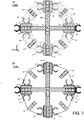
- FIG. 7A is a bottom view of the support device 100B of the third embodiment.
- the support device 100B has an annular flat plate 90 that substantially covers the second frame 10B below the second frame 10B (in the -Z axis direction).
- the annular flat plate 90 is connected to the second frame 10B by screwing or welding.
- the annular flat plate 90 is preferably made of a metal such as stainless steel, aluminum alloy, or chrome steel, and has a mesh structure so as not to be affected by water flow.
- the shooting mount 40 is arranged at every 45 degrees of the annular flat plate 90, and together with the shooting mount 40 arranged at the center of the cross of the second frame 10B, a maximum of nine photographing cameras CA (with a waterproof housing) can be arranged. Since the number of photographing cameras CA is large, it is possible to sufficiently secure overlap between each photograph in the photography of photogrammetry.
- FIG. 7B is a bottom view of the support device 100C of the fourth embodiment.
- the support device 100C has an octagonal flat plate 95 having substantially the same length in the XY axis direction as the second frame 10B instead of the second frame 10B.
- the octagonal flat plate 95 is connected to the first frame 10U by a support material 20.
- the octagonal flat plate 95 is also made of a metal such as stainless steel.
- the shooting mount 40 is arranged at the corner of the octagonal flat plate 95, and the shooting mount 40 is also arranged at the center of the octagonal flat plate 95, so that a maximum of nine photographing cameras CA can be arranged.
- the octagonal flat plate 95 of FIG. 7B is not formed with holes, but it is preferable that the octagonal flat plate 95 has a large hole like the flat plate 90 in order to make it less susceptible to the influence of water flow, and it is preferably a mesh structure.
- the annular flat plate 90 is attached below the second frame 10B, but as in the fourth embodiment, the annular flat plate 90 may be attached instead of the second frame 10B.
- the octagonal flat plate 95 is attached, Not limited to the octagonal flat plate, it may be a polygonal flat plate. Further, as in the third embodiment, a polygonal flat plate may be attached below the second frame 10B.
- the weight mount 80 shown in the second embodiment may be attached in the radial direction (in the case of a circular shape) or the longitudinal direction (in case of polygonal shape) of the flat plate.
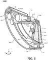
- FIGS. 8 to 10 show the support device 100D of the fifth embodiment.
- FIG. 8 is a perspective view of the support device 100D, showing a state before mounting an Unmanned submarine ROV such as an underwater drone.
- FIG. 9 is a perspective view of the frame of the support device 100D.
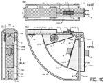
- FIG.10 (A) is a plan view of the support device 100D
- FIG.10 (B) is a front view thereof
- FIG.10 (C) is a side view thereof.
- the support device 100D can be equipped with at least one or more photographing camera CA (with a waterproof housing), an illumination light LT, a laser pointer LP, and the like. In the following description, each direction of up/down, front/back, and left/right is defined as shown in FIG. 8 .
- the support device 100D is detachably attached to an unmanned submarine ROV such as an underwater drone, as in the first to fourth embodiments. Further, the support device 100D is lighter and smaller than the first to fourth embodiments. It is preferable that the size of the support device 100D is configured to fit, for example, 40 cm or less in the X-axis direction, 15 cm or less in the Y-axis direction, and 40 cm or less in the Z-axis direction, and can be stored in a travel suitcase.
- the photographing camera CA and the illumination light LT attached to the support device 100D can be freely changed according to the application.
- the support device 100D includes a support material 20 and a lighting mount 30 for an illumination light attached to the second frame 10V, and a shooting mount 40 for a photographing camera attached to the first frame 10H and the second frame 10V, respectively.
- the laser pointer LP is not attached, but a pointer mount 60 for a laser pointer similar to that in the first embodiment may be attached to the support device 100D.
- the pointer mount 60 may be attached to the first frame 10H, the second frame 10V, or the support material 20, which will be described later.
- the support material 20 of the fifth embodiment may be a buoyant body similar to that of the first embodiment and so on.
- the support device 100D has a plate-shaped first frame 10H extending horizontally and a plate-shaped second frame 10V extending vertically so as to intersect the first frame 10U.
- the first frame 10H and the second frame 10V are formed of the same metal material or reinforced plastic by a 3D printer as the first frame 10U of the first embodiment.
- the width D4 of the first frame 10H and the second frame 10V is, for example, 3 cm to 8 cm, and the length of the first frame 10U in the front-rear direction and the length of the second frame 10V in the vertical direction are, for example, 20 cm to 40 cm.
- the widths D4 of the first frame 10H and the second frame 10V are the same, but may be different from each other.
- One end of the first frame 10H and one end of the second frame 10V are reinforced with a brace material 10AA and joined at an angle of 80-100 degrees.
- the other end of the first frame 10H and the other end of the second frame 10V are reinforced by the first reinforcing arm 10A1.
- first frame 10H has first mounting portions 10SH (10SH1, 10SH2) for mounting the support material 20 on the upper side (+ Z axis side) and the lower side (-Z axis side), respectively
- second frame 10V has a second mounting portion 10SV (10SV2, 10SV1) for mounting the support material 20 in the front (+ X-axis side) and the rear (-X-axis side) each.
- a part of the lower first mounting portion 10SH2 and a part of the front second mounting portion 10SV2 are reinforced by the second reinforcing arm 10A2.
- a rectangular support material 20 is attached to the first attachment portion 10SH1 and the second attachment portion 10SV1 when viewed from the Y-axis direction (XZ plane), and the first attachment portion 10SH2 and the second attachment portion 10SV2 can be attached the trapezoidal support material 20 when viewed from the Y-axis direction, but the shape is not limited to this.
- the shape of the first mounting portion 10SH and the second mounting portion 10SV may be a semicircular shape or a triangular shape.
- the first mounting portion 10SH and the second mounting portion 10SV are formed so as to cover four surfaces of the rectangular or trapezoidal support material 20, but have at least one surface, and it may be a structure to be tied up the support material 20 with a string or a rope.
- the support member 20 is a buoyant body having a shape that matches the first mounting portion 10SH1 and the second mounting portion 10SV1, and is a buoyant body having a shape that matches the first mounting portion 10SH2 and the second mounting portion 10SV2.
- the width (Y-axis direction) of the support material 20 coincides with the width D4 of the first mounting portion 10SH or the second mounting portion 10SH, but the support material 20 may be adjusted to be wide or narrow so that the weight of the attached photographing camera CA and lighting light LT, etc. can be offset.
- the support device 100D of the fifth embodiment also adjusts the positional relationship between the illumination light LT and the photographing camera CA in order to reduce the backscatter.
- Two lighting mounts 30 for the illumination lights LT are arranged behind the shooting mount 40 of one photographing camera CA facing forward (in the -X-axis direction), and two lighting mounts 30 for the illumination light LT are arranged above the imaging mount 40 of one photographing camera CA facing downward (in the + Z-axis direction).
- Each illumination light LT will be installed at the rear portion of the photographing camera CA in the photographing direction, and the backscatter caused by the light hitting the floating matter in the water can be minimized.
- the detachable mount 70 shown in FIGS. 10A and 10C is a mount for attaching / detaching the unmanned submarine ROV.
- the support devices 100 (100A to 100C) of the first to fourth embodiments have an axial center of gravity connecting the cross-shaped intersections of the first frame 10U and the cross-shaped intersections of the first frame 10U.
- the support device 100D of the fifth embodiment is symmetrical in the left-right (Y-axis) direction, but is not configured symmetrically in the front-rear (X-axis) direction. Therefore, when the unmanned submarine ROV mounts the support device 100D via the detachable mount 70, it may not be possible to balance in the front-rear direction. Therefore, the detachable mount 70 shown in FIGS. 10A and 10C is provided with a rail 72 for moving the detachable mount 70 and a lock mechanism 76 for locking the detachable mount 70.
- the rail 72 is made of plastic or metal, and the detachable mount 70 is movable along the rail 72.
- the operator attaches the photographing camera CA to the shooting mount 40 and the illumination light LT to the lighting mount 30 of the support device 100D, and then attaches the unmanned submarine ROV to the support device 100D via the detachable mount 70.
- the unmanned submarine ROV attached to the support device 100D is submerged in water, while the position of the detachable mount 70 is determined by the lock mechanism 76 in consideration of the balance of the support device 100D.
- the detachable mount 70 can be moved in the front-rear direction, but the detachable mount 70 may be fixed. In this case, it is preferable to provide the weight mount 80 described in FIG. 6 on the support device 100D. The weight mount 80 can move the weight WT in the front-rear direction to balance the support device 100D.
- the unmanned submarine ROV since five photographing cameras CA can be mounted on the support device 100, photographs for photogrammetry can be taken only by moving the unmanned submarine ROV in one direction (for example, the + X-axis direction).
- the unmanned submarine ROV since only two photographing cameras CA can be mounted, it is preferable that the unmanned submarine ROV reciprocates in one direction.
- the unmanned submarine ROV moves in the + X-axis direction, rolls +30 degrees to move in the -X-axis direction, and finally rolls -30 degrees and moves in the + X-axis direction, and photographs for photogrammetry can be taken, which is almost the same as that of the first embodiment.
- the support device of the present disclosure is effective for photogrammetry because a photographing camera that shoots from various angles can be arranged.
- a photographing camera that shoots from various angles can be arranged.
- it since it is possible for an operator to easily take a picture without diving into the water, it can be widely applied to a device for performing various operations in water.
Abstract
Description
- The present invention relates to a support device for a photographing apparatus used for photogrammetry that analyzes parallax information from a plurality of two-dimensional photographs to generate a three-dimensional photograph. In particular, it relates to a support device used for an unmanned submarine such as an underwater drone.
- Photogrammetry has begun to attract attention by recent improvements in image processing technology and computer processing speed. Photogrammetry is a technology that precisely digitizes images and positions from photographs taken from various angles and reproduces realistic three-dimensional objects from them. In order to facilitate photography for photogrammetry, for example,
JP Unexamined Patent Publication No. 2017-527812 A1 - However, in the scanner disclosed in
JP Unexamined Patent Publication No. 2017-527812 A1 - Therefore, the present invention provides a support device that can be attached to and detached from an unmanned submarine and can be attached with a photographing camera and an illumination light.
- The support device of this embodiment comprises a first flame that is detachable to an unmanned submarine, a second frame provided corresponding to the first frame, and a support material formed of a buoyancy material with a specific density of less than 1. The support device comprises a lighting mount for illumination lights attached to the first frame, the second frame or the support material, and a shooting mount for photographing cameras attached to the first flame, second frame or the support material.
- Further, the first frame may be formed in a cross shape, the second frame may be formed in a cross shape with arranged facing the first flame, and the support material may be arranged between the first frame and the second frame to be coupled to the first frame and the second frame.
The second frame has a flat plate having a size that covers the second frame, and a shooting mount may be attached to the flat plate instead of the support material or the second frame.
Further, it is preferable that the support device may include a connecting arm for connecting the first frame and the second frame, the first frame is formed in a straight line, and the support device has a first mounting portion for mounting the support material and a second mounting portion for mounting the support material. Then, it is preferable that the support material is arranged so as to intersect the first frame and connected by a connecting arm, and the support material is arranged on at least one of the first mounting portion and the second mounting portion. - The support device of another embodiment comprises the first frame formed in a cross shape to which the unmanned submarine is attached and detached, a flat plate corresponding to the size of the first frame, the support material which is arranged between the first frame and the flat plate so as to connect the first frame and the flat plate and formed of a buoyancy material having a specific density of less than 1. The support device further comprises a lighting mount for illumination lights that can be attached to the support material, and a shooting mount for photographing cameras that can be attached on a flat plat.
- The lighting mount is rotatable around an axis so that the lighting direction of the illumination light attached to the lighting mount can be adjusted, and the shooting mount is rotatable around an axis so that the shooting direction of the photographing camera attached to the shooting mount can be adjusted.
Further, it is preferable that the lighting mount and the shooting mount are positioned so that the light source position of the illumination light attached to the lighting mount is arranged behind the shooting angle of view of the photographing camera attached to the shooting mount. - The support material may have a first surface on which the lighting mount is arranged and a second surface recessed inward from the first surface.
Further, the support device may comprise a pointer mount for a laser pointer that irradiates an object with a laser beam on at least one of the first frame, the second frame, and the support material. The pointer mount is preferably rotatable around an axis so that the irradiation direction of the laser pointer attached to the pointer mount can be adjusted. - The support material may comprise a weight mount for weights for adjusting the balance of the support device.
Further, the support material may comprise a detachable mount on which the unmanned submarine is attached/detached to the first frame, and a rail for moving the detachable mount. - The support device of the present invention can be attached to and detached from an unmanned submarine, and can be attached a photographing camera and an illumination light.
-
-
FIG. 1 is a perspective view of a support device in a state where a photographing camera, an illumination light, and the like are attached. -
FIG. 2 is a plan view of a support device. -
FIG. 3 is a bottom view of the support device. -
FIG. 4 (A1) is a front view of the support material, andFIG. 4 (A2) is a side view of the support material.FIG. 4 (B) is a front view of the support device of another embodiment. -
FIG. 5 is an explanatory diagram showing a reason why a backscatter does not occur in the support device. -
FIG. 6 is a support device of a second embodiment, and is a diagram showing a weight mount particularly for weights. -
FIG. 7 (A) and FIG. 7 (B) are bottom views of the support devices of a third embodiment and a fourth embodiment in which nine photographing cameras can be mounted. -
FIG. 8 is a perspective view of a support device according to a fifth embodiment in a state where a photographing camera, an illumination light, and the like are attached. The support device of the fifth embodiment has a structure that emphasizes portability. -
FIG. 9 is a perspective view of a frame of a support device according to a fifth embodiment. -
FIG. 10(A) is a plan view of the support device of the fifth embodiment,FIG. 10(B) is a front view thereof, andFIG. 10(C) is a side view thereof. - Hereinafter, embodiments according to the present invention will be described in detail with reference to the drawings. In the present specification and the drawings, components having substantially the same functional configuration are designated by the same reference numerals. Therefore, duplicate description will be omitted. Also, in each drawing, the members of the device are not described according to the actual dimensions in order to emphasize them.
-
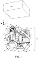
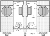
FIG. 1 is a perspective view of thesupport device 100 of a first embodiment, and shows a state before mounting an unmanned submarine ROV such as an underwater drone. Thesupport device 100 can be equipped with at least one or more photographing camera CA (with a waterproof housing), an illumination light LT, a laser pointer LP, and the like. In the following description, each direction of up/down, front/back, and left/right is defined as shown inFIG 1 . In the basic posture when thesupport device 100 is submerged in water, the water surface side is defined as the upper side (+ Z axis) and the water bottom side is defined as the lower side (-Z axis). The direction in which the laser pointer LP is arranged is defined as the front (+ X-axis) in the one-axis direction of one of the cross-shaped first frames described later, and the opposite side is defined as the rear (-X-axis). Then, in the other two-axis directions of the first frame, the back side of the paper surface inFIG. 1 is the right side (+ Y axis), and the front side of the paper surface is the left side (-Y axis). Further, in the following description, the direction of rotation centered on the front-rear axis is the roll direction, the direction of rotation centered on the right-left axis is the pitch direction, and the direction of rotation centered on the vertical axis is the yaw direction. - The
support device 100 is detachably attached to an unmanned submarine ROV such as an underwater drone. Thesupport device 100 can be flexibly attached to and detached from the newly introduced unmanned submarine ROV almost every year. - The size of the
support device 100 is configured to fit within, for example, 50 cm in the X-axis direction, 50 cm in the Y-axis direction, and 50 cm in the Z-axis direction. Since the unmanned submarine ROV is becoming smaller, thesupport device 100 may be even smaller in size. Thesupport device 100 of the first embodiment does not have an electrical connection or wireless / wired signal transmission / reception with the unmanned submarine ROV. However, thesupport device 100 may be electrically connected (power supply/signal) to the unmanned submarine ROV if necessary. - The photographing camera CA including the still image camera and the moving image camera and the illumination light LT attached to the
support device 100 can be freely changed according to the application. For example, for the photographing camera CA, there are a waterproof housing having a water depth of 60 m water resistant and a waterproof housing having a water depth of 250 m water resistant. Similarly, the illumination light LT also has a limit water depth of 60 m, 100 m, 150 m water resistant, or the like. Depending on the limit water depth of the unmanned submarine ROV, the water depth of the operating location, or the purpose of the user, the type of the photographing camera CA and its waterproof housing attached to thesupport device 100, or the illumination light LT can be changed. - The
support device 100 has a cross-shaped upperfirst frame 10U and a cross-shaped lowersecond frame 10B. Thefirst frame 10U and thesecond frame 10B are arranged so as to face each other. Further, thesupport device 100 has asupport material 20 arranged between thefirst frame 10U and thesecond frame 10U so as to connect thefirst frame 10U and thesecond frame 10B. Thesupport material 20 is formed by a buoyancy material having a specific density of less than 1. Further, thesupport device 100 includes alighting mount 30 for an illumination light attached to thesupport material 20, ashooting mount 40 for a photographing camera attached to thesecond frame 10B, and apointer mount 60 for a laser pointer attached to thesupport material 20. These members will be described in detail below with reference toFIGS.2 and3 . -
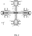
FIG. 2 is a plan view of thesupport device 100 observed from + Z axis direction, andFIG. 3 is a bottom view of thesupport device 100 observed from -Z axis direction. Thefirst frame 10U shown inFIG. 2 is formed of a metal such as stainless steel, an aluminum alloy, or chrome steel, or a fiber reinforced plastic having high strength made of glass fiber, carbon fiber, or the like, and made by a 3D printer and so on. A metal that easily rusts, for example, an iron material is not preferable in consideration of being used in the sea, but when an iron material is used for thefirst frame 10U, it is preferably protected by a rust preventive paint. The width of thefirst frame 10U is, for example, 3 cm to 8 cm, and the length of thefirst frame 10U in the front-rear direction or the right-left direction is, for example, 30 cm to 60 cm. In the first embodiment, the lengths of thefirst frame 10U in the front-rear direction and the right-left direction are the same, but the lengths may be different from each other. - The
second frame 10B shown inFIG. 3 is also made of the same metal material or reinforced plastic as thefirst frame 10U. Since thefirst frame 10U and thesecond frame 10B are connected by the plate-shapedsupport material 20 described later, they overlap each other when observed from upward or downward. In the first embodiment, the first and second cross-shaped frames are formed in a cross shape orthogonal to the X-axis direction and the Y-axis direction at 90 degrees, but the intersection angles may be changeable, for example, 45 degrees and 135 degrees. - The
support material 20 is fixed to the front-rear end (X-axis direction) and the left-right end (Y-axis direction) of thefirst frame 10U and thesecond frame 10B. Thesupport material 20 is a buoyant body having a specific gravity of 1 or less, and may be made of, for example, a glass fiber reinforced plastic material such as urethane foam, polyethylene foam, or, styrene foam. Since the unmanned submarine ROV may move deep into the water, reinforced styrofoam with pressure resistance and water resistance is particularly preferable. As described above, thesupport device 100 is attached with a photographing camera CA (with a waterproof housing), an illumination light LT, a laser pointer LP, and so on. In the first embodiment, at most five photographing cameras CA, eight illumination lights LT, and two laser pointer LPs are attached. - It is preferable that the volume of the
support material 20 buoyant body and the material of thesupport material 20 maybe selected so that the maximum weights of the attached photographing camera CA, the illumination light LT, the laser pointer LP, and so on can be offset. For example, when the photographing camera CA is lighter or the number of photographing cameras to be attached is small, a weight (not shown) is attached to thesupport device 100. For example, a weight of 1 kg may be taped to thesecond frame 10B. - The
support material 20 of the first embodiment is arranged at the front-rear end and the left-right end of thefirst frame 10U and thesecond frame 10B, respectively. For example, the front-rear support material 20 may be onesupport material 20 having a length equivalent to the length in the front-rear direction of thefirst frame 10U. That is, it may be composed of three support materials, onesupport material 20 extending in the X-axis direction and twosupport materials 20 extending in the Y-axis direction as shown inFIG. 2 or3 . When the total weight of the attached photographing camera CA, illumination light LT, and laser pointer LP becomes very heavy, the volume of the buoyant body can be increased by preparing onesupport material 20 that extends long in the X-axis direction and maximum weight can be offset. - As shown in
FIGS. 2 and3 , alighting mount 30 for the illumination light LT is attached to thefirst surface 21 of thesupport material 20 by screwing or bonding. In this embodiment, eight lighting mounts 30 are attached to eightfirst surfaces 21 of the foursupport materials 20. Thelight holder 32 may be rotatable to the axis of the base of thelighting mount 30 so that thelighting mount 30 can direct the lighting direction of the illumination light LT according to the shooting direction of the photographing camera CA. Alternatively, when the base of thelighting mount 30 and thelight holder 32 are fixed (non-rotatable), screw holes for attaching thelighting mount 30 to thesupport material 20 are arranged on the circumference, for example, every 30 degrees, and the base of 30 may be rotatable about the axis with respect to thesupport material 20. When the base of thelighting mount 30 and thelight holder 32 are fixed, a turntable may be provided under the base of thelighting mount 30. - When the shooting direction of the photographing camera CA is limited, it is not always necessary to provide eight lighting mounts 30, and for example, only four lighting mounts 30 may be arranged. However, when creating a 3D model with photogrammetry, it is preferable that the photograph taken is sharp or not blur. In order to take a sharp picture, increase the shutter speed to make a picture without blurring due to movement, raise the aperture value (F value) to make a picture without blur, and lower the ISO value to make a picture with less noise. Therefore, it is preferable to arrange
lighting mount 30 with 4 or more, preferably 6 or more to secure the amount of light from the illumination light LT. - As shown in
FIGS. 2 and3 , two pointer mounts 60 for laser pointer LP are attached to thefourth surfaces 27 at both ends of thesupport material 20 in the X-axis direction by screwing or bonding. Pointer mounts 60 may be attached to both ends of thesupport material 20 in the Y-axis direction. When the length of thefirst frame 10U in the front-rear direction is longer than the length in the left-right direction, it is preferable that the pointer mounts 60 are attached to both ends of the longer one. The laser pointers LP create to form the light spots emitted from the laser pointer LP on the bottom of the water or a cliff (wall surface) in the water, and utilize the distance between the two light spots in the photograph taken by the photographing camera CA. Then it is possible to give dimensions to the created digital 3D model. It is preferable that thepointer mount 60 is configured so that the direction of the light spot can be rotated about the axis according to the shooting direction of the photographing camera. In the first embodiment, thepointer mount 60 is attached to thefourth surface 27 of thesupport material 20, but it may be provided on thefirst frame 10U or thesecond frame 10B. - The
detachable mount 70 shown inFIG. 2 is a mount for attaching and detaching the unmanned submarine ROV. If the unmanned submarine ROV has an attachment / detachment device, it can be fitted with the attachment / detachment device. When the unmanned submarine ROV does not have an attachment / detachment device, the unmanned submarine ROV can be attached / detached with the tape by passing a tape or band by passing band through the hole (not shown) of thedetachable mount 70. InFIG. 2 , although threedetachable mounts 70 are provided, not limited to three. For example, only one at the center of the cross may be provided, or five at the center and five on the front, back, left, and right may be provided, these arrangements are good. Further, thedetachable mount 70 may be movable on thefirst frame 10U. Thefirst frame 10U and the unmanned submarine ROV may be attached or detached with a tape or a band without providing thedetachable mount 70. - The shooting mount 40 shown in
FIG. 3 is a mount for attaching and detaching the waterproof housing of the photographing camera CA. Since the bottom of the water (seabed) is often photographed, it is preferable that theshooting mount 40 is attached to thesecond frame 10B. Further, if thesupport material 20 has a structure (seeFIG. 6 ) that penetrates thesecond frame 10B downward (-Z axis), theshooting mount 40 may be attached to the bottom surface of thesupport member 20. - The
shooting mount 40 has a function equivalent to that of a universal head of a tripod. For example, the function of shootingmount 40 is configured so that the roll direction, pitch direction, and yaw direction can be freely set. The reference axis of theshooting mount 40 is the -Z axis direction in which the photographing camera CA housed in the waterproof housing observes the water bottom (seabed). Assuming that the -Z axis direction of theshooting mount 40 is 0 degrees, it is preferable that the photographing camera CA can photograph from the -90 degree direction to the +90 degree direction in the roll direction and from the -90 degree direction to the +90 degree direction in the pitch direction. - Photographing for creating a digital 3D model with photogrammetry is that each photo has sufficient overlap. That is, it is preferable that the first photograph and the second photograph overlap by 60% (horizontal direction) or 80% (vertical direction) or more. In order to create a more precise 3D model, it is preferable that the object to be photographed is shot from at least 3 different angles. Therefore, it is preferable that the
support device 100 can be equipped with five photographing cameras CA in advance in the directions of downward, diagonally forward, downward, diagonally downward to the left, diagonally downward to the right, and diagonally downward to the rear. Conventional photogrammetry in water was done by a handheld camera and a diver takes pictures of one place from multiple angles. When five photographing cameras CA with a different shooting direction are installed, pictures for photogrammetry are taken just by moving the unmanned submarine ROV in one direction (for example, + X axis direction). It is preferable that five shooting mounts 40 are provided, but for example, if a steep cliff (wall surface) in water is mainly photographed, three shooting mounts 40 may be provided. -
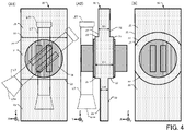
FIG. 4 (A1) is thesupport material 20 of the first embodiment,FIG. 4 (A1) is a view of observing thesupport material 20 from the + Y axis direction, andFIG. 4 (A2) is a view of observing thesupport material 20 from the -X axis direction.FIG. 4B is a view of thesupport material 20 of the second embodiment observed from the + Y axis direction. As shown inFIG. 4 (A2) , thesupport material 20 has afirst surface 21, asecond surface 23, and athird surface 25 on one side, and thefirst surface 21 and thesecond surface 23 and athird surface 25 on the opposite side. Therefore, thefirst surface 21 and thefirst surface 21 form a thickness D1, thesecond surface 23 and thesecond surface 23 form a thickness D2, and thethird surface 25 and thethird surface 25 are Form thickness D3. Thelighting mount 30 is arranged on thefirst surface 21. - As shown in
FIG. 4(A) , the illumination light LT generally has a circular body cross section and a light source head LTH having a trumpet-shaped diameter. Further, the illumination light LT generally has a battery lid LTT for inserting a primary battery or a secondary battery, and the battery lid LTT is often larger in diameter than the body. Therefore, in the rotation range of the illumination light LT attached to thelighting mount 30, it is preferable that thesecond surface 23 is recessed inward from thefirst surface 21 so that the light source head LTH or the battery lid LTT does not interfere with thesupport material 20. And thethird surface 25 is preferably recessed inward from thefirst surface 21. Since there are various shapes of the illumination light LT, it is not necessary to provide thesecond surface 23 or thethird surface 25 which are recessed inward from thefirst surface 21. - The step 22 (step between the first surface and the second surface and the step between the first surface and the third surface) of the
support material 20 shown inFIG. 4 (A) is formed a straight line parallel to the X-axis or the Y-axis. However, as shown inFIG. 4B , thestep 22 of thesupport material 20 may be formed in a circumferential shape. - As described above, in order to create a 3D model by photogrammetry, it is desired that the photographing camera CA captures a sharp photograph. Therefore, it is preferable that the light from the illumination light LT is as strong as possible. However, when the light from the illumination light LT hits a floating object in water, a backscatter (backscattering) phenomenon occurs in which the light is scattered and diffusely reflected in the direction in which the light comes, then blocking the view. In order to reduce this backscatter, the positional relationship between the illumination light LT and the photographing camera CA is adjusted.
-
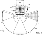
FIG. 5 is a right-side view of thesupport device 100 on which four illumination lights LT and three photographing cameras CA are described. The illumination light LT on the + X-axis side of the four illumination lights LT faces forward (+ X-axis direction), and the illumination light LT on the -X-axis side faces rearward (-X-axis direction). Further, the two illumination lights LT of the four illumination lights LT are directed downward (in the -Z axis direction). When the four illumination lights LT attached to thelighting mount 30 are rotatably moved downward from the horizontal direction, the locus LC of the light source head LTH of the illumination light LT becomes a locus indicated by a dotted line. - In
FIG. 5 , the front (+ X-axis direction) photographing camera CA is drawn with the front (+ X-axis direction) as the shooting direction. The rear (-X-axis direction) photographing camera CA is drawn with the rear (-X-axis direction) as the shooting direction. And the photographing camera CA in the center is drawn so as to shoot in the water bottom direction (-Z axis direction). The angle of view AF varies depending on whether the shooting lens of each photographing camera CA is a wide-angle lens or a telephoto lens. When theshooting mount 40 is rotated in each direction, the total angle of view range of these three photographing camera CA becomes maximum angle of view WAF shown in a fan-shaped. - As shown in
FIG. 5 , the locus LC of the light source head LTH is inside (+ Z-axis direction) from the maximum angle of view WAF of the photographing camera CA. When the locus LC of the light source head LTH is inside the maximum angle of view WAF of the photographing camera CA, the backscatter can be reduced. The length of the illumination light LT varies from about 10 cm to 40 cm or more. It is preferable that the locus LC of the various light source heads LTH is inside the maximum angle of view WAF of the photographing camera CA. Therefore, it is preferable that the center position of theillumination mount 30 is located above half the length of thesupport material 20 in the Z-axis direction. Further, it is preferable that theshooting mount 40 is attached to the bottom surface of thesecond frame 10B or thesupport material 20 so as to be as lower as possible in thesupport device 100. Although not shown, thelighting mount 30 may be provided at the upper end (+ Z axis) of thesupport material 20. Although the right-side view of thesupport device 100 is shown inFIG. 5 , the positional relationship between thelighting mount 30 and theshooting mount 40 is the same in the left-side view, the front-side view, and the rear-side view. -
FIG. 6 is a side view of thesupport device 100A of the second embodiment. Thesupport material 20A of thesupport device 100A has a structure that connects thefirst frame 10U and thesecond frame 10B and penetrates thesecond frame 10B downward (-Z axis). Therefore, theshooting mount 40 is attached to the bottom surface of thesupport material 20A. Further, thesupport device 100A has aweight mount 80 that thesupport device 100 of the first embodiment does not have. - When the
lighting mount 30 and theshooting mount 40 are equipped with an illumination light LT and a photographing camera CA of the same weight, The support device 100 (and 100A) has a center of gravity in an axial shape connecting the cross-shaped intersection of thefirst frame 10U and the cross-shaped intersection of thefirst frame 10U in a well-balanced manner. However, when the weights of the illumination light LT and the photographing camera CA are different, or when the illumination light LT or the photographing camera CA is attached to some of the lighting mounts 30 or some of the shooting mounts, The center of gravity deviates from the axis connecting the intersections of the crosses. Further, even if thesupport device 100 is equipped with the illumination light LT and the photographing camera CA in a well-balanced manner, the support device 100 (and 100A) may be tilted due to the water flow (ocean current). On the contrary, when photographing a steep cliff (wall surface) in water, it may be better to keep the support device 100 (and 100A) tilted at a certain angle and photograph with the photographing camera CA. - The weight mount 80 shown in
FIG. 6 has arail 82, apedestal 84, and alocking mechanism 86. Therail 82 has a groove and is made of a metal such as plastic or stainless steel or an aluminum alloy. Thepedestal 84 is made of plastic or metal and has a retainingrod 85 for fastening the weight WT and a protrusion (not shown) that enters the groove of therail 82, and thepedestal 84 can move along therail 82. Further, thepedestal 84 has alock mechanism 86 for locking thepedestal 84 on therail 82. - It is preferable that the weight WT has a hole (not shown) and unevenness so that the stacking does not shift. And it is preferable that the weight of the weight WT can be adjusted by inserting the hole of the weight WT into the
fastening rod 85 and stacking, for example, 250g of the weight WT in 1 step, 2 steps, and 5 steps. The weight WT of the flat plate may be fastened with tape or the like without providing thefastening rod 85 on thepedestal 84. - An example of the balance adjustment of the
support device 100A will be explained with reference toFIG 6 . It is assumed that the balance between the total weight and buoyancy of thesupport device 100A including the photographing camera CA, the illumination light LT, and the laser pointer LP matches the front (+ X-axis side)pedestal 84, the four weight WTs, and the rear (-X-axis side)pedestal 84 with two weights WT. Further, it is assumed that thefront pedestal 84 is locked by thelock mechanism 86 at the center position of therail 82, and therear pedestal 84 is also locked by thelock mechanism 86 at the center position of therail 82. If the front is slightly lighter (about 50g) in this state, the lock of thepedestal 84 on which the two rear weight WTs are placed is released, and thepedestal 84 is moved forward and locked by thelock mechanism 86. It is easier to make fine adjustments when the weight WT moves the pedestal 84 a long distance. - Although
FIG. 6 shows an example in which thepedestal 84 is manually moved and locked by thelock mechanism 86, a ball screw, an electric motor, and an electric circuit may be added to therail 82 to automatically adjust the balance. Although the right-side view of thesupport device 100A is shown inFIG. 6 , when observed from the front side view, thesupport device 100A also has aweight mount 80 having arail 82 extending in the Y-axis direction. -
FIG. 7A is a bottom view of thesupport device 100B of the third embodiment. Thesupport device 100B has an annularflat plate 90 that substantially covers thesecond frame 10B below thesecond frame 10B (in the -Z axis direction). The annularflat plate 90 is connected to thesecond frame 10B by screwing or welding. The annularflat plate 90 is preferably made of a metal such as stainless steel, aluminum alloy, or chrome steel, and has a mesh structure so as not to be affected by water flow. Theshooting mount 40 is arranged at every 45 degrees of the annularflat plate 90, and together with theshooting mount 40 arranged at the center of the cross of thesecond frame 10B, a maximum of nine photographing cameras CA (with a waterproof housing) can be arranged. Since the number of photographing cameras CA is large, it is possible to sufficiently secure overlap between each photograph in the photography of photogrammetry. -
FIG. 7B is a bottom view of thesupport device 100C of the fourth embodiment. Thesupport device 100C has an octagonalflat plate 95 having substantially the same length in the XY axis direction as thesecond frame 10B instead of thesecond frame 10B. The octagonalflat plate 95 is connected to thefirst frame 10U by asupport material 20. The octagonalflat plate 95 is also made of a metal such as stainless steel. Theshooting mount 40 is arranged at the corner of the octagonalflat plate 95, and theshooting mount 40 is also arranged at the center of the octagonalflat plate 95, so that a maximum of nine photographing cameras CA can be arranged. - The octagonal
flat plate 95 ofFIG. 7B is not formed with holes, but it is preferable that the octagonalflat plate 95 has a large hole like theflat plate 90 in order to make it less susceptible to the influence of water flow, and it is preferably a mesh structure. In the third embodiment, the annularflat plate 90 is attached below thesecond frame 10B, but as in the fourth embodiment, the annularflat plate 90 may be attached instead of thesecond frame 10B. Further, in the fourth embodiment, the octagonalflat plate 95 is attached, Not limited to the octagonal flat plate, it may be a polygonal flat plate. Further, as in the third embodiment, a polygonal flat plate may be attached below thesecond frame 10B. - When a flat plate is attached instead of the
second frame 10B as in the fourth embodiment, theweight mount 80 shown in the second embodiment may be attached in the radial direction (in the case of a circular shape) or the longitudinal direction (in case of polygonal shape) of the flat plate. -
FIGS. 8 to 10 show thesupport device 100D of the fifth embodiment.FIG. 8 is a perspective view of thesupport device 100D, showing a state before mounting an Unmanned submarine ROV such as an underwater drone.FIG. 9 is a perspective view of the frame of thesupport device 100D.FIG.10 (A) is a plan view of thesupport device 100D,FIG.10 (B) is a front view thereof, andFIG.10 (C) is a side view thereof. Thesupport device 100D can be equipped with at least one or more photographing camera CA (with a waterproof housing), an illumination light LT, a laser pointer LP, and the like. In the following description, each direction of up/down, front/back, and left/right is defined as shown inFIG. 8 . - The
support device 100D is detachably attached to an unmanned submarine ROV such as an underwater drone, as in the first to fourth embodiments. Further, thesupport device 100D is lighter and smaller than the first to fourth embodiments. It is preferable that the size of thesupport device 100D is configured to fit, for example, 40 cm or less in the X-axis direction, 15 cm or less in the Y-axis direction, and 40 cm or less in the Z-axis direction, and can be stored in a travel suitcase. The photographing camera CA and the illumination light LT attached to thesupport device 100D can be freely changed according to the application. - In the fifth embodiment, up to two photographing cameras CA and four illumination lights LT are attached to the
support device 100D. Thesupport device 100D includes asupport material 20 and alighting mount 30 for an illumination light attached to thesecond frame 10V, and ashooting mount 40 for a photographing camera attached to thefirst frame 10H and thesecond frame 10V, respectively. - In the fifth embodiment, the laser pointer LP is not attached, but a
pointer mount 60 for a laser pointer similar to that in the first embodiment may be attached to thesupport device 100D. In the fifth embodiment, thepointer mount 60 may be attached to thefirst frame 10H, thesecond frame 10V, or thesupport material 20, which will be described later. Thesupport material 20 of the fifth embodiment may be a buoyant body similar to that of the first embodiment and so on. - In particular, as shown in
FIG. 9 , thesupport device 100D has a plate-shapedfirst frame 10H extending horizontally and a plate-shapedsecond frame 10V extending vertically so as to intersect thefirst frame 10U. Thefirst frame 10H and thesecond frame 10V are formed of the same metal material or reinforced plastic by a 3D printer as thefirst frame 10U of the first embodiment. - The width D4 of the
first frame 10H and thesecond frame 10V is, for example, 3 cm to 8 cm, and the length of thefirst frame 10U in the front-rear direction and the length of thesecond frame 10V in the vertical direction are, for example, 20 cm to 40 cm. In the fifth embodiment, the widths D4 of thefirst frame 10H and thesecond frame 10V are the same, but may be different from each other. One end of thefirst frame 10H and one end of thesecond frame 10V are reinforced with a brace material 10AA and joined at an angle of 80-100 degrees. The other end of thefirst frame 10H and the other end of thesecond frame 10V are reinforced by the first reinforcing arm 10A1. - Further, the
first frame 10H has first mounting portions 10SH (10SH1, 10SH2) for mounting thesupport material 20 on the upper side (+ Z axis side) and the lower side (-Z axis side), respectively, and thesecond frame 10V has a second mounting portion 10SV (10SV2, 10SV1) for mounting thesupport material 20 in the front (+ X-axis side) and the rear (-X-axis side) each. A part of the lower first mounting portion 10SH2 and a part of the front second mounting portion 10SV2 are reinforced by the second reinforcing arm 10A2. - A
rectangular support material 20 is attached to the first attachment portion 10SH1 and the second attachment portion 10SV1 when viewed from the Y-axis direction (XZ plane), and the first attachment portion 10SH2 and the second attachment portion 10SV2 can be attached thetrapezoidal support material 20 when viewed from the Y-axis direction, but the shape is not limited to this. For example, the shape of the first mounting portion 10SH and the second mounting portion 10SV may be a semicircular shape or a triangular shape. The first mounting portion 10SH and the second mounting portion 10SV are formed so as to cover four surfaces of the rectangular ortrapezoidal support material 20, but have at least one surface, and it may be a structure to be tied up thesupport material 20 with a string or a rope. - Shape of support material:
Thesupport member 20 is a buoyant body having a shape that matches the first mounting portion 10SH1 and the second mounting portion 10SV1, and is a buoyant body having a shape that matches the first mounting portion 10SH2 and the second mounting portion 10SV2. InFIGS. 8 and10 , the width (Y-axis direction) of thesupport material 20 coincides with the width D4 of the first mounting portion 10SH or the second mounting portion 10SH, but thesupport material 20 may be adjusted to be wide or narrow so that the weight of the attached photographing camera CA and lighting light LT, etc. can be offset. - Similarly to the first embodiment, the
support device 100D of the fifth embodiment also adjusts the positional relationship between the illumination light LT and the photographing camera CA in order to reduce the backscatter. Two lighting mounts 30 for the illumination lights LT are arranged behind theshooting mount 40 of one photographing camera CA facing forward (in the -X-axis direction), and two lighting mounts 30 for the illumination light LT are arranged above theimaging mount 40 of one photographing camera CA facing downward (in the + Z-axis direction). Each illumination light LT will be installed at the rear portion of the photographing camera CA in the photographing direction, and the backscatter caused by the light hitting the floating matter in the water can be minimized. - The
detachable mount 70 shown inFIGS. 10A and 10C is a mount for attaching / detaching the unmanned submarine ROV. The support devices 100 (100A to 100C) of the first to fourth embodiments have an axial center of gravity connecting the cross-shaped intersections of thefirst frame 10U and the cross-shaped intersections of thefirst frame 10U. On the other hand, thesupport device 100D of the fifth embodiment is symmetrical in the left-right (Y-axis) direction, but is not configured symmetrically in the front-rear (X-axis) direction. Therefore, when the unmanned submarine ROV mounts thesupport device 100D via thedetachable mount 70, it may not be possible to balance in the front-rear direction. Therefore, thedetachable mount 70 shown inFIGS. 10A and 10C is provided with arail 72 for moving thedetachable mount 70 and alock mechanism 76 for locking thedetachable mount 70. - The
rail 72 is made of plastic or metal, and thedetachable mount 70 is movable along therail 72. The operator attaches the photographing camera CA to theshooting mount 40 and the illumination light LT to thelighting mount 30 of thesupport device 100D, and then attaches the unmanned submarine ROV to thesupport device 100D via thedetachable mount 70. The unmanned submarine ROV attached to thesupport device 100D is submerged in water, while the position of thedetachable mount 70 is determined by thelock mechanism 76 in consideration of the balance of thesupport device 100D. - In the fifth embodiment, the
detachable mount 70 can be moved in the front-rear direction, but thedetachable mount 70 may be fixed. In this case, it is preferable to provide theweight mount 80 described inFIG. 6 on thesupport device 100D. The weight mount 80 can move the weight WT in the front-rear direction to balance thesupport device 100D. - In the first embodiment, since five photographing cameras CA can be mounted on the
support device 100, photographs for photogrammetry can be taken only by moving the unmanned submarine ROV in one direction (for example, the + X-axis direction). On the other hand, in the fifth embodiment, since only two photographing cameras CA can be mounted, it is preferable that the unmanned submarine ROV reciprocates in one direction. For example, the unmanned submarine ROV moves in the + X-axis direction, rolls +30 degrees to move in the -X-axis direction, and finally rolls -30 degrees and moves in the + X-axis direction, and photographs for photogrammetry can be taken, which is almost the same as that of the first embodiment. - The support device of the present disclosure is effective for photogrammetry because a photographing camera that shoots from various angles can be arranged. In addition, since it is possible for an operator to easily take a picture without diving into the water, it can be widely applied to a device for performing various operations in water.
-
- 100 (100A-100D) ... Support device
- 10U, 10H ... 1 st frame, 10B, 10S ... 2nd frame
- 10SH (10SH1,10SH2) ... First mounting portion
- 10SV (10SV2, 10SV1) ... Second mounting portion
- 20 ... Support material, 30 ... Lighting mount
- 40 ...
Shooting mount 60 ... Pointer mount - 70 ... Detachable mount, 72 ... Rail, 76 ... Lock mechanism
- 80 ... Weight mount, 82 ... Rail, 86 ... Lock mechanism
- 90, 95 ... Flat plate
- CA ... Photographing camera
- LT ... Illuminating light
- LP ... Laser pointer
- WT ... Weight
- ROV ... Unmanned submarine (underwater drone)
Claims (12)
- A support device (100), comprising:a first flame (10U, 10H) for attaching and detaching an unmanned submarine (ROV);a second frame (10B, 10V) provided corresponding to the first frame (10U, 10H);a support material (20) coupled to the first flame (10U, 10H) and the second flame (10B, 10V) and formed of a small buoyancy material with a specific density of less than 1.a lighting mount (30) for illumination lights (LT) attached to the first frame (10U, 10H), second frame (10B, 10V) or support material (20); anda shooting mount (40) for photographing cameras (CA) attached to the first flame (10U, 10H), the second frame (10B, 10V) or support material (20).
- The support device (100) of claim 1,wherein the first flame (10U) is formed in a cross shape;the second frame (10B) is formed in a cross shape with arranged facing the first frame (10U);the support material (20) is arranged between the first frame (10U) and the second frame (10B) so as to connect the first frame (10U) and the second frame (10B).
- The support device (100) of claim 2,wherein the second frame (10B) has a flat plate having a size covering the second frame (10B); andthe shooting mount (40) is attached to the flat plate (90) in place of the support material (20) or the second frame (10B).
- The support device (100) of claim 1, further comprising:a connection arm (10A1, 10A2) for connecting the first frame (10H) and the second frame (10V); whereinthe first frame (10H) is formed in a straight line and has a first mounting portion (10SH) for attaching the support material (20);the second frame (10V) is formed in a straight line and has a second mounting portion (10SV) for mounting the support material (20) and is arranged so as to intersect the first frame (10H) to be connected by the connecting arm; andthe support material (20) is arranged on at least one of the first mounting portion and the second mounting portion.
- A support device (100) comprising:a first frame (10U) formed in a cross shape to which the unmanned submarine (ROV) is attached and detached;a flat plate corresponding to the size of the first frame (10U);a support material (20) arranged between the first frame (10U) and the flat plate so as to connect the first frame (10U) and the flat plate (95), and formed of a buoyancy material having a specific gravity of less than 1;a lighting mount (30) for illumination light (LT) attached to the support material (20);a shooting mount (40) for a photographing camera (CA) attached to the flat plate.
- The support device (100) of any one of claims 1 to 5,the lighting mount (30) is rotatable around an axis so that the illumination direction of the illumination light (LT) attached to the lighting mount (30) can be adjusted;the shooting mount (40) is rotatable around the axis so that the shooting direction of the photographing camera (CA) attached to the shooting mount (40) can be adjusted.
- The support device (100) of claim 6, wherein the lighting mount (30) and the shooting mount (40) are positioned so that the light source position of the illumination light (LT) attached to the lighting mount (30) is arranged behind the shooting angle of view of the photographing camera (CA) mounted on the shooting mount (40).
- The support device (100) of any one of claims 1 to 5, wherein the support material (20) has a first surface on which the lighting mount (30) is arranged and a second surface recessed inward from the first surface.
- The support device (100) of any one of claims 1 to 8, further comprising a pointer mount (60) for a laser pointer (LP) that irradiates an object with laser light on at least one place of the first frame (10H), the second frame (10V) and the support material (20).
- The support device (100) of claim 7,
wherein the pointer mount (60) is rotatable about an axis so that the irradiation direction of the laser pointer (LP) attached to the pointer mount (60) can be adjusted. - The support device (100) of any one of claims 1 to 10, further comprising a weight mount (80) for weights for adjusting the balance of the support device (100).
- The support device (100) of any one of claims 1 to 11, comprising:a detachable mount (70) to which the unmanned submarine (ROV) is attached and detached from the first frame (10U); anda rail (72) to move the detachable mount (70).
Applications Claiming Priority (2)
| Application Number | Priority Date | Filing Date | Title |
|---|---|---|---|
| JP2020213122 | 2020-12-23 | ||
| JP2021145931A JP7364632B2 (en) | 2020-12-23 | 2021-09-08 | support equipment |
Publications (2)
| Publication Number | Publication Date |
|---|---|
| EP4020078A2 true EP4020078A2 (en) | 2022-06-29 |
| EP4020078A3 EP4020078A3 (en) | 2022-08-03 |
Family
ID=79230736
Family Applications (1)
| Application Number | Title | Priority Date | Filing Date |
|---|---|---|---|
| EP21214114.7A Pending EP4020078A3 (en) | 2020-12-23 | 2021-12-13 | Support device |
Country Status (2)
| Country | Link |
|---|---|
| US (1) | US20220196203A1 (en) |
| EP (1) | EP4020078A3 (en) |
Citations (1)
| Publication number | Priority date | Publication date | Assignee | Title |
|---|---|---|---|---|
| JP2017527812A (en) | 2014-09-10 | 2017-09-21 | ファロ テクノロジーズ インコーポレーテッド | Method for optical measurement of three-dimensional coordinates and calibration of a three-dimensional measuring device |
Family Cites Families (33)
| Publication number | Priority date | Publication date | Assignee | Title |
|---|---|---|---|---|
| US2506095A (en) * | 1948-04-13 | 1950-05-02 | Mantz Albert Paul | Vibration-damping camera mount |
| US4272177A (en) * | 1980-05-27 | 1981-06-09 | Ottenheimer Charles J | Multiple camera mounting bracket |
| US4514067A (en) * | 1983-02-14 | 1985-04-30 | Gallegos John C | Twin camera, shoulder carry, rotary, stabilization pod |
| US6262761B1 (en) * | 1998-11-05 | 2001-07-17 | Nature Vision, Inc. | Submersible video viewing system |
| US7463280B2 (en) * | 2003-06-03 | 2008-12-09 | Steuart Iii Leonard P | Digital 3D/360 degree camera system |
| US7834910B2 (en) * | 2006-03-01 | 2010-11-16 | David M. DeLorme | Method and apparatus for panoramic imaging |
| US20120154521A1 (en) * | 2010-10-26 | 2012-06-21 | Townsend Julie A | 360-degree camera head for unmanned surface sea vehicle |
| US9036001B2 (en) * | 2010-12-16 | 2015-05-19 | Massachusetts Institute Of Technology | Imaging system for immersive surveillance |
| US9498883B2 (en) * | 2011-12-15 | 2016-11-22 | Korea Institute Of Ocean Science & Technology | Multi-joint underwater robot having complex movement functions of walking and swimming and underwater exploration system using same |
| EP2915324B1 (en) * | 2012-11-05 | 2020-07-08 | 360 Heros, Inc. | 360 degree camera mount and related photographic and video system |
| US9402026B2 (en) * | 2013-01-05 | 2016-07-26 | Circular Logic Systems, Inc. | Spherical panoramic image camera rig |
| US20140362176A1 (en) * | 2013-01-05 | 2014-12-11 | Patrick A. St. Clair | Spherical panoramic imaging system |
| US9413930B2 (en) * | 2013-03-14 | 2016-08-09 | Joergen Geerds | Camera system |
| US20160344999A1 (en) * | 2013-12-13 | 2016-11-24 | 8702209 Canada Inc. | SYSTEMS AND METHODs FOR PRODUCING PANORAMIC AND STEREOSCOPIC VIDEOS |
| EP2887328B1 (en) * | 2013-12-19 | 2016-04-20 | Axis AB | Monitoring devices slidably mounted on a rail releasably locked to predetermined positions |
| CN106464785A (en) * | 2014-05-20 | 2017-02-22 | 奈克斯特Vr股份有限公司 | Methods and apparatus including or for use with one or more cameras |
| US9602702B1 (en) * | 2014-09-08 | 2017-03-21 | Sulaiman S. Albadran | Video camera with multiple data input |
| US20160295108A1 (en) * | 2015-04-01 | 2016-10-06 | Cheng Cao | System and method for panoramic imaging |
| US20160349600A1 (en) * | 2015-05-26 | 2016-12-01 | Gopro, Inc. | Multi Camera Mount |
| CN107637060B (en) * | 2015-05-27 | 2020-09-29 | 谷歌有限责任公司 | Camera rig and stereoscopic image capture |
| US9575394B1 (en) * | 2015-06-10 | 2017-02-21 | Otoy, Inc. | Adaptable camera array structures |
| DE102015118997A1 (en) * | 2015-11-05 | 2017-05-11 | Berliner Kta Shareholder Gmbh | Camera mount for stereoscopic panorama shots |
| US10577125B1 (en) * | 2015-12-28 | 2020-03-03 | Vr Drones Llc | Multi-rotor aircraft including a split dual hemispherical attachment apparatus for virtual reality content capture and production |
| JP6643657B2 (en) * | 2016-02-26 | 2020-02-12 | パナソニックIpマネジメント株式会社 | Imaging device |
| US10151968B2 (en) * | 2016-08-09 | 2018-12-11 | Brandon T. Roots | Multi-camera mount |
| US10447993B2 (en) * | 2016-09-27 | 2019-10-15 | Laduma, Inc. | Stereoscopic 360 degree digital camera systems |
| US11412134B2 (en) * | 2016-11-30 | 2022-08-09 | Laduma, Inc. | Underwater digital camera systems |
| US10288988B2 (en) * | 2017-01-20 | 2019-05-14 | Spherica, Inc. | Apparatus and method for stabilizing virtual reality camera configurations |
| US10291828B1 (en) * | 2017-04-13 | 2019-05-14 | Facebook, Inc. | Scalable three-dimensional, 360-degree virtual reality camera system |
| US9921464B1 (en) * | 2017-05-03 | 2018-03-20 | Seung Kwon Choi | Gimbal for 360-degree video and picture shooting |
| US10324360B2 (en) * | 2017-05-09 | 2019-06-18 | Jared Stanton | Camera rig |
| USD857083S1 (en) * | 2018-11-05 | 2019-08-20 | Bonsai Technology Company | 360 degree multiple camera rig |
| US10935783B1 (en) * | 2019-09-17 | 2021-03-02 | Aquabyte, Inc. | Optical system for capturing digital images in an aquaculture environment in situ |
-
2021
- 2021-12-13 EP EP21214114.7A patent/EP4020078A3/en active Pending
- 2021-12-23 US US17/560,933 patent/US20220196203A1/en active Pending
Patent Citations (1)
| Publication number | Priority date | Publication date | Assignee | Title |
|---|---|---|---|---|
| JP2017527812A (en) | 2014-09-10 | 2017-09-21 | ファロ テクノロジーズ インコーポレーテッド | Method for optical measurement of three-dimensional coordinates and calibration of a three-dimensional measuring device |
Also Published As
| Publication number | Publication date |
|---|---|
| US20220196203A1 (en) | 2022-06-23 |
| EP4020078A3 (en) | 2022-08-03 |
Similar Documents
| Publication | Publication Date | Title |
|---|---|---|
| US9491339B1 (en) | Camera system | |
| CN106628026B (en) | Unmanned ship and unmanned ship system | |
| US10288988B2 (en) | Apparatus and method for stabilizing virtual reality camera configurations | |
| WO2003025854A2 (en) | Co-registered acoustical and optical cameras for underwater imaging | |
| JP6357044B2 (en) | Float, photographic device with float | |
| JP2007022349A (en) | Ship front side monitoring system | |
| KR20180099650A (en) | Active stabilization system | |
| WO2018186750A1 (en) | Camera assisted control system for an underwater vehicle | |
| EP4020078A2 (en) | Support device | |
| CN108924389A (en) | A kind of stable holder of laser night vision | |
| CN208198848U (en) | A kind of airborne aerial device and the unmanned plane containing it | |
| JP7364632B2 (en) | support equipment | |
| CN112584053A (en) | Binocular vision laser emission system and method | |
| CN111163252B (en) | Panoramic shooting device, panoramic shooting system, shooting method and aircraft | |
| CN211118405U (en) | Camera shooting angle adjusting device | |
| JP3829194B2 (en) | Imaging equipment for surveying underwater ecosystem | |
| RU2679922C1 (en) | Towed device for mapping seabed objects and their visual verification | |
| JP2010276772A (en) | Autonomous imaging apparatus | |
| KR20200036195A (en) | Drone | |
| JP2021167134A (en) | Underwater survey device | |
| CN209823863U (en) | Cloud platform device and have unmanned vehicles of this cloud platform device | |
| JP2007101512A (en) | Exploration apparatus for fresh water region and sea water region | |
| US6795648B1 (en) | High resolution photographic system | |
| US20160266473A1 (en) | Imaging device holder | |
| CN108397652B (en) | Film and television special shooting robot holder |
Legal Events
| Date | Code | Title | Description |
|---|---|---|---|
| PUAI | Public reference made under article 153(3) epc to a published international application that has entered the european phase |
Free format text: ORIGINAL CODE: 0009012 |
|
| STAA | Information on the status of an ep patent application or granted ep patent |
Free format text: STATUS: THE APPLICATION HAS BEEN PUBLISHED |
|
| AK | Designated contracting states |
Kind code of ref document: A2 Designated state(s): AL AT BE BG CH CY CZ DE DK EE ES FI FR GB GR HR HU IE IS IT LI LT LU LV MC MK MT NL NO PL PT RO RS SE SI SK SM TR |
|
| PUAL | Search report despatched |
Free format text: ORIGINAL CODE: 0009013 |
|
| AK | Designated contracting states |
Kind code of ref document: A3 Designated state(s): AL AT BE BG CH CY CZ DE DK EE ES FI FR GB GR HR HU IE IS IT LI LT LU LV MC MK MT NL NO PL PT RO RS SE SI SK SM TR |
|
| RIC1 | Information provided on ipc code assigned before grant |
Ipc: G03B 17/08 20210101ALI20220627BHEP Ipc: G03B 37/00 20210101ALI20220627BHEP Ipc: G03B 17/56 20210101ALI20220627BHEP Ipc: G01C 11/02 20060101ALI20220627BHEP Ipc: G03B 15/03 20210101AFI20220627BHEP |
|
| STAA | Information on the status of an ep patent application or granted ep patent |
Free format text: STATUS: REQUEST FOR EXAMINATION WAS MADE |
|
| 17P | Request for examination filed |
Effective date: 20230113 |
|
| RBV | Designated contracting states (corrected) |
Designated state(s): AL AT BE BG CH CY CZ DE DK EE ES FI FR GB GR HR HU IE IS IT LI LT LU LV MC MK MT NL NO PL PT RO RS SE SI SK SM TR |
|
| STAA | Information on the status of an ep patent application or granted ep patent |
Free format text: STATUS: EXAMINATION IS IN PROGRESS |
|
| 17Q | First examination report despatched |
Effective date: 20231207 |