EP4019916B1 - Pyranometer - Google Patents
Pyranometer Download PDFInfo
- Publication number
- EP4019916B1 EP4019916B1 EP20216772.2A EP20216772A EP4019916B1 EP 4019916 B1 EP4019916 B1 EP 4019916B1 EP 20216772 A EP20216772 A EP 20216772A EP 4019916 B1 EP4019916 B1 EP 4019916B1
- Authority
- EP
- European Patent Office
- Prior art keywords
- thermopile
- based sensor
- pyranometer
- optical filter
- diffusor
- Prior art date
- Legal status (The legal status is an assumption and is not a legal conclusion. Google has not performed a legal analysis and makes no representation as to the accuracy of the status listed.)
- Active
Links
Images


Classifications
-
- G—PHYSICS
- G01—MEASURING; TESTING
- G01J—MEASUREMENT OF INTENSITY, VELOCITY, SPECTRAL CONTENT, POLARISATION, PHASE OR PULSE CHARACTERISTICS OF INFRARED, VISIBLE OR ULTRAVIOLET LIGHT; COLORIMETRY; RADIATION PYROMETRY
- G01J1/00—Photometry, e.g. photographic exposure meter
- G01J1/02—Details
- G01J1/0252—Constructional arrangements for compensating for fluctuations caused by, e.g. temperature, or using cooling or temperature stabilization of parts of the device; Controlling the atmosphere inside a photometer; Purge systems, cleaning devices
-
- G—PHYSICS
- G01—MEASURING; TESTING
- G01J—MEASUREMENT OF INTENSITY, VELOCITY, SPECTRAL CONTENT, POLARISATION, PHASE OR PULSE CHARACTERISTICS OF INFRARED, VISIBLE OR ULTRAVIOLET LIGHT; COLORIMETRY; RADIATION PYROMETRY
- G01J1/00—Photometry, e.g. photographic exposure meter
- G01J1/02—Details
- G01J1/0271—Housings; Attachments or accessories for photometers
-
- G—PHYSICS
- G01—MEASURING; TESTING
- G01J—MEASUREMENT OF INTENSITY, VELOCITY, SPECTRAL CONTENT, POLARISATION, PHASE OR PULSE CHARACTERISTICS OF INFRARED, VISIBLE OR ULTRAVIOLET LIGHT; COLORIMETRY; RADIATION PYROMETRY
- G01J1/00—Photometry, e.g. photographic exposure meter
- G01J1/02—Details
- G01J1/04—Optical or mechanical part supplementary adjustable parts
- G01J1/0407—Optical elements not provided otherwise, e.g. manifolds, windows, holograms, gratings
- G01J1/0474—Diffusers
-
- G—PHYSICS
- G01—MEASURING; TESTING
- G01J—MEASUREMENT OF INTENSITY, VELOCITY, SPECTRAL CONTENT, POLARISATION, PHASE OR PULSE CHARACTERISTICS OF INFRARED, VISIBLE OR ULTRAVIOLET LIGHT; COLORIMETRY; RADIATION PYROMETRY
- G01J1/00—Photometry, e.g. photographic exposure meter
- G01J1/42—Photometry, e.g. photographic exposure meter using electric radiation detectors
- G01J2001/4266—Photometry, e.g. photographic exposure meter using electric radiation detectors for measuring solar light
- G01J2001/4285—Pyranometer, i.e. integrating over space
Definitions
- the present invention relates to a pyranometer for measuring an irradiance amount, e.g. solar irradiance amount.
- a pyranometer is a measuring instrument that detects the irradiance amount, e.g. the solar irradiance amount, incident on a surface.
- thermopile-based sensor pyranometers can be grouped in two different categories, that is thermopile-based sensor pyranometers and silicon semiconductor-based pyranometers.
- thermopile-based sensor pyranometers the irradiance is measured by a sensor based on thermopiles and designed to measure a substantially broad band of the radiation flux density, from about a 180° field of view angle.
- the thermopile-based sensor is arranged below a transparent dome, particularly a dome made of glass, the latter limiting the spectral response from about 190 to about 4000 nanometers, particularly from about 300 to about 2800 nanometers, while substantially preserving about the 180° field of view.
- the glass dome has the function of protecting the thermopile-based sensor from the external environment.
- Pyranometers can be used in conjunction with other systems, among others solar simulators, photovoltaic systems, and meteorological stations.
- the solar radiation measured by the pyranometer is used for determining other parameters and/or performances of the system, for example the photovoltaic module effective power. Therefore, the measurement accuracy of a pyranometer is one outmost aspect of this measuring instrument. Particularly, the measurement accuracy of the pyranometer is even more one outmost aspect in climate applications where changes of parts of a percent over years are recorded.
- Pyranometers can be characterized by their degree of spectral sensitivity (spectral response), that is the capacity of the pyranometer to sense the radiation within a certain range of the radiation spectrum.
- the radiation spectrum that is measured by a pyranometer can be influenced (may change due to) by many factors, among others the incident angle of the radiation (e.g. solar radiation) (sun angle) and the atmospheric conditions, i.e. the presence of clouds and aerosols.
- the pyranometer spectral response should be preferably as constant as possible for different ranges of the radiation spectrum (light spectrum).
- a classification of the pyranometer spectral response to different light spectra is specifically provided by the standard ISO 9060:2018.
- thermopile-based pyranometers are provided with a black coated thermopile sensor and with a glass dome.
- the black coated thermopile sensor is capable of substantially absorbing (almost) all ration (e.g. solar radiation), thus, obtaining a substantially flat spectrum ranging from about 300 to about 50,000 nm.
- the glass dome limits the spectral response from about 300 to about 2800 nm, cutting off the portion above about 2800 nm, while substantially preserving the 180° field of view.
- a substantially constant pyranometer spectral response is not achieved in pyranometers comprising micro thermopile-based sensors arranged in combination with a diffusor.
- Micro thermopile-based sensors are characterized by a faster response time and by a more stable thermal behavior.
- micro thermopile-based sensors are combined with an optical diffusor.
- the diffusor is an optical element (optical diffusor) that is configured to diffuse and transmit the light incident thereon, toward the receiving surface of the radiation sensor.
- the optical diffusor is positioned on top of the micro thermopile-based sensor so as to substantially oppose the receiving surface of the micro thermopile-based sensor. As a result, the light external to the pyranometer and incident on the diffusor, can be diffused on the receiving surface of the micro thermopile-based sensor.
- thermopile-based sensor when a micro thermopile-based sensor is combined with an optical diffusor, a considerable variation of the spectral response with the wavelength occurs.
- a combined spectral response (combination of the thermopile-based sensor spectral response and diffusor spectral responses), substantially varies with the wavelength of the relevant spectrum.
- Document JP 2009 162508 A describes an actinometer including a sensor for detecting intensity of incident light, an optical diffusion plate that is superimposed on the sensor, and an optical filter arranged between the optical diffusion plate and the sensor.
- the sensor is a multi-junction type semiconductor sensor wherein a plurality of cells having mutually each different spectral sensitivity characteristic is laminated in the film thickness direction.
- Document EP 3 480 570 A1 describes a pyranometer comprising a light sensor, a first lens arranged to face a light-receiving surface of the light sensor, and a light-shielding ring arranged between the light sensor and the first lens, the light-shielding ring having a light-transmissive region allowing transmission of light at some angles of incidence in the light passing through the first lens.
- Document US 2020/256729 A1 describes an optical measurement method and system.
- the system includes, and method applies, a light source, a beam splitter, at least one filter, an output photodetector for acquiring data of a sample, and a correction photodetector for correcting and maintaining output intensity from the light source.
- the filter is located between the light source and the correction photodetector for normalizing the spectrum of the input light being applied to input light correction.
- the filter may be incorporated into the beam splitter and may be tuned to filter light from the light source for providing non-zero transmission of light with a near-zero gradient for wavelengths in a portion of the spectrum of the input light being applied to the sample and read by the output photodetector.
- Document US 3 876 880 A describes a pyranometer which serves to measure the total radiation of the solar spectrum provided with an internal cooling system which is intended to provide compensation for drift of filters.
- An object of the present invention is enhancing the measurement accuracy of a pyranometer.
- a pyranometer comprising a dome; a thermopile-based sensor comprising a receiving surface; a diffusor configured to diffuse radiation external to the pyranometer and passing through the dome, toward the receiving surface of thermopile-based sensor; and at least one optical filter arranged in an optical path of the radiation in front of the receiving surface of the thermopile-based sensor so as to modify the spectral composition of the radiation measured by the thermopile-based sensor.
- an optical filter arranged in the optical path of the radiation allows to modify the spectral composition of the radiation passing through the dome and/or the diffusor and that is measured by the thermopile-based sensor.
- the radiation incident on the dome and/or diffusor may be solar radiation.
- the pyranometer has a substantially invariant spectral response.
- the spectral response of the pyranometer is not affected by the variation caused by the inclusion of an optical diffusor in the optical path and/or by the spectral selectivity of the thermopile-based sensor.
- the optical filter also provides (at least partial) compensation for the Fresnel losses of the dome.
- the measured output of the pyranometer will depend on the irradiance levels, as well as on changes in the irradiance spectrum resulting from the changes in the solar zenith angle (sun angle) and the atmospheric conditions, e.g. presence of clouds.
- an optical filter according to the above allows the response of the pyranometer to be substantially invariant under different specifically spectral conditions, particularly atmospheric conditions such as wind, temperature, rain etc. etc...
- the present disclosure provides for a thermopile-based pyranometer having an invariant spectral response.
- the spectral response may be invariant under different solar and/or atmospheric conditions (time of the day, sun angle, clear or cloudy sky, level of soiling on dome of pyranometer, etc.), that influence the spectrum of the solar irradiance. More specifically, the measurement accuracy of the pyranometer is enhanced.
- the at least one optical filter at least partly compensates a spectral selectivity of the thermopile-based sensor and/or the diffusor, and/or the dome (i.e. of the thermopile-based sensor, of the diffusor, or of the dome; or of the combined thermopile-based sensor and diffusor, and/or of the dome).
- an optical filter that at least partially compensates the spectral selectivity of the thermopile-based sensor and/or the diffusor allows the pyranometer to be substantially invariant to changing atmospheric conditions, wherein the latter results in changes in the spectral composition of the incoming radiation, particularly changes in the spectral composition of the incoming solar radiation. Accordingly, the measurement accuracy of the pyranometer is enhanced.
- the at least one optical filter modifies the spectral composition of the radiation (solar radiation) measured by the thermopile-based sensor such that spectral selectivity based on a spectral absorptance and a spectral transmittance of the thermopile-based sensor, and/or the diffusor, and/or the dome, has a maximum percentual deviation of about ⁇ 3% from a mean value, between in a wavelength range of the solar radiation spectrum ranging from about 350 nm to about 1500 nm.
- the optical filter having the above configuration makes the pyranometer response spectrally flat, particularly within a maximum percentual deviation from a mean value. Accordingly, the measurement accuracy of the pyranometer is enhanced.
- the at least one optical filter may be configured such that a transmittance of the at least one optical filter is greater for a spectrum wavelength lower than about 400 nm than the transmittance of the at least one optical filter for a spectrum wavelength greater than about 700 nm.
- the optical filter having the above configuration makes the pyranometer response substantially spectrally flat (or at least flatter), particularly by at least compensating the spectral characteristics of the diffusor and/or of the thermopile-based sensor. Accordingly, the measurement accuracy of the pyranometer is enhanced.
- the at least one optical filter comprises a one or more layers, each layer being configured to have different refracting, transmission, absorption and/or reflection characteristics for a given specified radiation (solar radiation) wavelength value or range.
- the optical filter having the above configuration makes the pyranometer response substantially spectrally flat, particularly by compensating the spectral characteristics of the diffusor and/or of the thermopile-based sensor. Accordingly, the measurement accuracy of the pyranometer is enhanced.
- the at least one optical filter may be arranged on the optical path between the diffusor and the receiving surface of the thermopile-based sensor.
- the at least one optical filter may be arranged to substantially face the receiving surface of the thermopile-based sensor, particularly wherein the at least one optical filter may be arranged to substantially face an active black coating surface of the thermopile-based sensor.
- the at least one optical filter is embedded in a material of the active black coating of the thermopile-based sensor.
- thermopile-based sensor may be at least partly located in a housing, and wherein the at least one optical filter may be arranged to substantially cover a window of the housing.
- the at least one optical filter may be arranged to at least partially cover an external surface of the diffusor.
- the at least one optical filter may be arranged on an inner part of the diffusor.
- the at least one optical filter may be arranged to at least partially cover the inner surface and/or the outer surface of the dome.
- the at least one optical filter may comprise one or more vacuum deposited dielectric metal layers.
- the at least one optical filter is a transmission interference filter.
- the pyranometer may further comprise at least one collimator configured to collimate the radiation (solar radiation) impinging on the receiving surface of the thermopile-based sensor.
- a collimator configured to collimate the radiation (solar radiation) impinging on the receiving surface of the thermopile-based sensor allows to modify the optical path followed by the radiation (solar radiation) in the pyranometer. Specifically, the transmission of the radiation (solar radiation) is optimized.
- a distance of an optical path between the diffusor and the thermopile-based sensor may be set such that the radiation (solar radiation) diffused by the diffusor on the receiving surface of the thermopile-based sensor has a substantially cone shape.
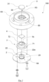
- the pyranometer according to the present invention is indicated in its entirety with the reference number 100.
- the pyranometer 100 comprises a dome 1.
- the dome 1 may be an outer dome of the pyranometer 100. In other words, when mounted on the pyranometer 100, the dome 1 may form the outermost dome 1 of the pyranometer 100.
- an outer surface 11 of the dome 1 substantially faces an environment 13 external to the pyranometer 100.
- an inner surface 12 of the dome 1 substantially encloses a cavity 10.
- the cavity 10 is an air cavity underneath the dome 1.
- the inner surface 12 of the dome 1 substantially faces the cavity 10.
- the cavity 10 substantially corresponds to the space that encloses the cavity 10.
- the cavity 10 may have a substantially hemispherical shape and includes a bottom opening 14 having a substantially circular shape.
- the dome 1 may comprise an edge 15.
- the edge 15 may be a perimetric edge substantially forming the rim of the dome 1.
- the edge 15 may have preferably a substantially annular shaped surface. Particularly, a difference between the external radius, that is the radius of the outer surface 11, and the internal radius, that is the radius of the inner surface 12, substantially corresponds the thickness of the dome 1.
- the dome 1 is at least partially transparent to a radiation (e.g. solar light).
- the radiation may be solar radiation.
- the dome 1 is configured to limit the spectral response from about 190 to about 4000 nanometers (nm), preferably from about 300 to about 2800 nanometers (nm), while particularly substantially preserving the 180° field of view.
- the transparency of the dome 1 may be particularly such that at least about 60%, more particularly at least about 70% of the incident radiation (e.g. solar radiation or light) in the relevant spectral range may pass therethrough.
- the dome 1 is configured to allow at least a portion of the radiation spectrum to be transmitted from the external environment 13, through the outer surface 11, through the material forming the dome 1 and through the inner surface 12, into the cavity 10. In the cavity 10, the radiation can be measured as will be described in more details hereafter.
- the dome 1 may be made of any suitable at least partially transparent material that allows the transmission of a radiation (particularly solar radiation or light) therethrough.
- the dome 1 may be made of any material having such physical/chemical characteristics so as to physically protect the measuring surface of the pyranometer 100 yet at the same time being transparent to (most) of the light (at least partially transparent for a spectrum of radiation (e.g. solar radiation) the pyranometer 100 is intended to detect).
- the dome 1 may be made of glass, quartz or sapphire.
- the dome 1 may be made of a transparent thermoplastic polymeric material, i.e. poly(methyl methacrylate) (PMMA) also known as acrylic, acrylic glass, or plexiglass.
- PMMA poly(methyl methacrylate)
- the pyranometer 100 comprises a pyranometer housing 6.
- the pyranometer housing 6 may be, or may comprise, a container configured to contain the components of the pyranometer 100, e.g. a thermopile-based sensor 2, a diffusor 3, a optical filter 4, and/or a control unit 5. These components, as well as their functions, will be hereafter described in more details.
- the pyranometer housing 6 may be provided with one or more levelling feet(s) 61 for supporting the pyranometer housing 6 on a supporting surface S. The levelling feet(s) 61 also allows the pyranometer housing 6 to be levelled on the supporting surface S.
- the pyranometer housing 6 may comprise a first (outer) portion 62 and a second (inner) portion 63.
- the first portion 62 may be an outer covering portion arranged to cover and, thus, protect the second portion 63 from the environment 13 external to the pyranometer 100.
- the first portion 62 may be configured to, at least partially, enclose the second portion 63.
- the first portion 62 may be a sunscreen removably connected by one or more clip(s) to the second portion 63.
- the second portion 63 may be configured to support the thermopile-based sensor 2, a diffusor 3, and/or a optical filter 4.
- the second portion 63 may comprise a supporting plate 64 that is configured to support the thermopile-based sensor 2.
- thermopile-based sensor 2 may be directly, or indirectly, connected to the supporting plate 64.
- the supporting plate 64 may directly be, or indirectly, removably coupled to the second portion 63 so as to enclose the thermopile-based sensor 2 therebetween.
- the thermopile-based sensor 2 may be located in a cavity surrounded by the second portion 63 of the housing 6 and the supporting plate 64.
- a top surface of the first portion 62 may be also directly, or indirectly, removably coupled to the edge 15 of the dome 1 such that the dome 1 can be connected to the housing 6, as shown in Figs. 1 and 5 to 8 .
- the pyranometer 100 comprises the thermopile-based sensor 2.
- the thermopile-based sensor 2 is a measuring sensor configured to measure the radiation impinging the pyranometer 100.
- the radiation impinging the pyranometer 100 may be solar radiation.
- the thermopile-based sensor 2 may be based on thermopiles particularly suitable to measure the broad band of the radiation flux density specifically from a substantially 180° field of view angle.
- a thermopile specifically is an electronic device that converts thermal energy into electrical energy and comprises several thermocouples connected in series or in parallel. The thermopile works on the principle of the thermoelectric effect of generating a voltage when its dissimilar metals or thermo-couples are exposed to a temperature difference.
- Thermocouples operate by measuring the temperature differential from their junction point to the point in which the thermocouple output voltage is measured. Once a closed circuit is made up of more than one metal and there is a difference in temperature between junctions and points of transition from one metal to another, a current is produced as if generated by a difference of potential between the junctions being at different temperatures.
- the pyranometer 100 of the present disclosure particularly is a thermopile pyranometer (also referred to as thermo-electric pyranometer).
- thermopile pyranometer 100 particularly detects light of about 300 to about 2800 nm with a largely flat spectral sensitivity.
- the thermopile-based sensor 2 comprises a black coating which absorbs (particularly all) radiation (e.g. solar radiation or modified solar radiation modified e.g. in its spectral composition by the optical elements in front of it such as the dome 1 and/or the diffusor 3) impinging thereon.
- the active (hot) junctions of the thermocouples are located beneath (or in correspondence with or adjacent to) the black coating surface and are heated by the radiation absorbed from the black coating.
- the passive (cold) junctions of the thermocouples are (particularly fully) protected from radiation and in thermal contact with the pyranometer housing 6, which particularly serves as a heat-sink.
- the passive (cold) junctions of the thermocouples are in contact with a thermopile housing 23 that may be in thermal contact with the pyranometer housing 6, so as to substantially dissipate the heat to or through the pyranometer housing 6. This specifically reduces or prevents any alteration from yellowing or decay when measuring the temperature in the shade, thus impairing the measure of the solar irradiance by the pyranometer 100.
- thermopile-based sensor 2 may be a micro thermopile-based sensor.
- the thermopile may be located in a TO (transistor outline) housing having a diameter in the range of about 1 mm to about 20 mm or lower than about 10 mm.
- the TO housing and/or active component(s) of thermopile-based sensor 2 may be micro machined.
- the thermopile-based sensor 2 comprises a receiving surface 22 and a second opposite (bottom) surface 21.
- the receiving surface 22 of the thermopile-based sensor 2 may comprise, or may correspond to, the black coating surface.
- the second surface 21 substantially faces the supporting plate 64. Particularly, the second surface 21 may directly, or indirectly, contact the supporting plate 64 such that the thermopile-based sensor 2 is directly, or indirectly, supported by supporting plate 64.
- the receiving surface 22 is configured to substantially receive the radiation impinging the pyranometer 100.
- the radiation impinging the pyranometer 100 may be solar radiation.
- the solar radiation impinging the pyranometer 100 is at least partially transmitted through the dome 1 and diffused on the receiving surface 22 of the thermopile-based sensor 2, by means of the diffusor 3. Therefore, the diffusor 3 is specifically arranged to diffuse the radiation passing through the dome 1, on the receiving surface 22 of the thermopile-based sensor 2.
- the thermopile-based sensor 2 and the diffusor 3 may be stacked one on top of the other.
- the thermopile-based sensor 2 may be located in a housing 23 provided with a window 22a.
- the housing 23 may have or define a cavity configured to integrally at least partly contain the thermopile-based sensor 2.
- the window 22a of the housing 23 may be arranged to substantially face the receiving surface 22 of the thermopile-based sensor 2 on a bottom side. Particularly, a gap may be present between the receiving surface 22 and the window 22a in order to particularly prevent thermal leakage which may degrade the sensor performance.
- the window 22a of the housing 23 may be arranged to substantially face a second (bottom) surface 32 of the diffusor 3 on an upper side. Particularly, a gap may be present between the second (bottom) surface 32 of the diffusor 3 and the window 22a.
- the window 22a of the housing 23 may be substantially arranged between , but not being in contact with, the second (bottom) surface 32 of the diffusor 3, and the receiving surface 22 of the thermopile-based sensor 2.
- the window 22a of the housing 23 is at least partially transparent to the radiation (light).
- the window 22a of the housing 23 may have a transparency such that at least about 60%, more particularly at least about 70% of the incident radiation (light) in the relevant spectral range may pass therethrough.
- the window 22a of the housing 23 may be also part of an optical path of the radiation that will be described in detail hereinafter.
- the pyranometer 100 comprises the diffusor 3.
- the diffusor 3 is configured to diffuse radiation (e.g. solar radiation or light) external to the pyranometer 100, and passing through the dome 1, toward the receiving surface 22 of thermopile-based sensor 2. Accordingly, the radiation impinging the receiving surface 22 of the thermopile-based sensor 2 can be measured by the thermopile-based sensor 2.
- radiation e.g. solar radiation or light
- the diffusor 3 is an optical element that has an incident first or top surface 31 substantially facing the cavity 10 of the dome 1, particularly when the diffusor 3 is mounted on the pyranometer 100.
- the diffusor 3 is arranged such that the incident surface 31 substantially faces the inner surface 12 of the dome 1, in cavity 10.
- the diffusor 3 may be located in a through-opening 65 provided in the second portion 63 of the pyranometer housing 6 such that the incident surface 31 of the diffusor 3 substantially faces the inner surface 12 of the dome 1.
- the diffusor 3 comprises a second (bottom) surface 32 that is substantially opposite to the incident first or top surface 31 and at least one side surface 33.
- the second surface 32 is substantially opposite to the incident surface 31 and substantially faces the receiving surface 22 of the thermopile-based sensor 2, when the diffusor 3 is mounted on the pyranometer 100.
- the diffusor 3 is arranged such that the second bottom surface 32 substantially faces the receiving surface 22 of the thermopile-based sensor 2.
- the incident surface 31 may be a flat circularly shaped surface, a conically shaped surface, a convex surface, a concave surface, or an inverted conical surface.
- the diffusor 3 may be axisymmetric, that is symmetric about a longitudinal axis X3 of the diffusor 3.
- the diffusor 3 may be a rotationally symmetric body having a longitudinal axis X3.
- the diffusor 3 may have a substantially cylindrically shaped side surface 33 and/or comprising a conically shaped incident first or top surface 31.
- the diffusor 3 may be arranged such that the second surface 32 substantially faces toward the receiving surface 22 of the thermopile-based sensor 2, whereas the incident surface 31 substantially faces towards the inner surface 12 of the dome 1.
- the radiation or light (or solar radiation) external to the dome 1 enters the cavity 10 through the dome 1.
- the radiation or light impinges the incident surface 31 of the diffusor 3 and it is at least partly transmitted through the diffusor 3 towards the thermopile-based sensor 2, particularly the receiving surface 22 of the thermopile-based sensor 2, as shown in Fig. 4 .
- the radiation or light (e.g. solar radiation) reaching the thermopile-based sensor 2 can be thus measured by the latter.
- the diffusor 3 may comprise or be made of any material that allows a light incident thereon to be diffused and transmitted through the diffusor 3.
- the diffusor 3 may comprise, or be made, of at least partially porous material, such as bubble quartz.
- the pyranometer 100 may comprise at least one control unit 5.
- the control unit 5 may be operatively connected to the thermopile-based sensor 2.
- the control unit 5 may be a controller, preferably a micro controller.
- the control unit 5 may be located in the pyranometer housing 6.
- control unit 5 may be configured to modify a radiation output (solar radiation output) measured by the thermopile-based sensor 2, based on a correction factor.
- control unit 5 may be configured to perform a post processing correction of the radiation measured by the thermopile-based sensor 2. Specifically, by modifying a radiation output measured by the thermopile-based sensor 2, based on a correction factor, a post processing correction can be performed. Accordingly, a more precise irradiance measurement can be achieved.
- the pyranometer 100 further comprises at least one optical filter 4.
- the optical filter 4 may be a solar radiation optical filter.
- the optical filter 4 is arranged in an optical path of the radiation, particularly in front of the receiving surface 22 of the thermopile-based sensor 2.
- the optical path is a path followed by the radiation (solar radiation) while passing through the components of the pyranometer, and before impinging the receiving surface 22 of the thermopile-based sensor 2.
- the radiation impinging the receiving surface 22 of the thermopile-based sensor 2 can be filtered by the optical filter 4.
- the spectral composition of the radiation impinging on or measured by the thermopile-based sensor 2 is modified by the optical filter 4.
- the optical path followed by the radiation may comprise (starting from the environment 13 external to the pyranometer 100): the outer surface 11 of the dome 1, the inner material of the dome 1, the inner surface 12 of the dome 1, the cavity 10, the incident surface 31 of the diffusor 3, the inner material of the diffusor 3, the second bottom surface 32 of the diffusor 3, the window 22a of the housing 23 and/or the receiving surface 22 of the thermopile-based sensor 2.
- the radiation external to the pyranometer 100 particularly the solar radiation, and impinging the pyranometer 100, may pass through the above-mentioned elements and/or surfaces, before reaching the receiving surface 22 of the thermopile-based sensor 2.
- the "spectral composition" of the radiation refers to the energy composition of the solar radiation in a range(s) of frequency(ies) (or range(s) of wavelength(s)) of the solar electromagnetic radiation (solar light).
- modifying the spectral composition of the radiation refers to modifying the solar radiation flux density in a range(s) of frequency(ies) (or range(s) of wavelength(s)) of the solar radiation, before the latter impinges the receiving surface 22 of the thermopile-based sensor 2.
- the optical filter 4 may be configured to at least partly compensate a spectral selectivity of the thermopile-based sensor 2, and/or of the diffusor 3 and/or of the dome 1.
- the thermopile-based sensor 2 and/or the diffusor 3 may have a spectral selectivity or spectral transmission property that varies with the wavelength of the (solar) radiation spectrum as shown in Fig. 9 with regard to the diffusor 3.
- the thermopile-based sensor 2 and/or the diffusor 3 may exhibit a greater transmission property (total transmittance) for solar radiation within a certain wavelength range of the solar radiation spectrum, and a different, particularly lower, transmission property (total transmittance) for a solar radiation within a different wavelength range of the solar radiation spectrum.
- the transmission property of the thermopile-based sensor 2, of the diffusor 3 and/or of the dome 1, and/or of a combination thereof is not substantially constant within a relevant wavelength range of the solar radiation spectrum.
- the optical filter 4 may be configured to at least partly compensate a spectral selectivity of the thermopile-based sensor 2 and/or the diffusor 3.
- the optical filter 4 may be configured to have a spectral selectivity or spectral transmission property that is substantially opposite or complementary to the spectral selectivity or spectral transmission property of the thermopile-based sensor 2 and/or of the diffusor 3, particularly within specified (predetermined or predeterminable) wavelength range(s). More particularly, the spectral selectivity or spectral transmission property may be in a wavelength range of the solar radiation spectrum ranging from about 350 nm to about 1500 nm. Specifically, the optical filter 4 at least partly compensates the spectral selectivity of a combination of both the thermopile-based sensor 2 and the diffusor 3.
- the optical filter 4 is configured to modify (correct) the spectral composition of the solar radiation measured by the thermopile-based sensor 2 such that the spectral selectivity based on a spectral absorptance and a spectral transmittance of the thermopile-based sensor 2 and the diffusor 3 has a maximum percentual deviation of about ⁇ 3% from a mean value in a wavelength range of the radiation spectrum ranging from about 350 nm to about 1500 nm, particularly as required by ISO 9060:2018.
- the spectral selectivity particularly is proportional to a product of the spectral absorbance and the spectral transmittance of the thermopile-based sensor 2 and the diffusor 3 and of the dome 1, specifically of a combination of both the thermopile-based sensor 2 and the diffusor 3.
- the spectral selectivity or property of the combination of the thermopile-based sensor 2 and the diffusor 3 should not exceed by about ⁇ 3% from the mean value in the wavelength range of the radiation spectrum (solar radiation spectrum) ranging from about 350 nm to about 1500 nm.
- the optical filter 4 in the optical path of the radiation (solar radiation) and which is configured to modify the spectral composition of the radiation measured by the thermopile-based sensor 2 so as to at least partly compensate the spectral selectivity of the thermopile-based sensor 2, of the diffusor 3 or of the combined thermopile-based sensor 2 and diffusor 3, it is possible to achieve the above mentioned maximum percentual deviation of about ⁇ 3% from a mean value in a wavelength range of the radiation spectrum ranging from about 350 nm to about 1500 nm.
- the optical filter 4 in the optical path of the radiation (e.g. solar radiation) and which is configured to modify the spectral composition of the radiation measured by the thermopile-based sensor 2, it is possible to achieve a spectral error that is less than 0.5% for standard spectra and which particularly results in a constraint over the entire range between about 280 nm to about 3500 nm.
- the radiation e.g. solar radiation
- the optical filter 4 may be configured such that a (total) transmittance of the optical filter 4 is greater for a spectrum wavelength lower than about 400 nm than the (total) transmittance of the optical filter 4 for a spectrum wavelength greater than about 700 nm.
- the optical filter 4 may be configured to greatly transmit radiation (e.g. solar radiation) having a spectrum wavelength lower than about 400 nm (UV light), while slightly transmit radiation having a spectrum wavelength greater than about 700 nm (IR light), as shown in Fig. 10 .
- the optical filter 4 is configured to mostly suppress, or at least reducing, the transmission of radiation within the infrared range, while increasing the transmission of radiation within the UV light.
- the at least one optical filter 4 may comprise one or more layers, each layer being configured to substantially have different transmission and/or reflection characteristics for a specified radiation (solar radiation) wavelength value or range.
- the one or more layers may comprise one or more layers of metallic and/or nonmetallic material, each layer having different transmission and/or reflection characteristics for a specified radiation wavelength value, or range.
- the one or more layers may be selected such that a desired spectral selectivity or spectral transmission property of the at least one optical filter 4 is achieved.
- the one or more layers may be selected so as to compensate a spectral selectivity of the thermopile-based sensor 2, and/or the diffusor 3, and/or of the dome 1, and/or of a combination thereof.
- the at least one optical filter 4 is a transmission interference filter.
- a transmission interference filter comprises one or more thin dielectric layer(s) configured to transmit up to a certain amount of the incident radiation at a certain range(s) of frequencies (wavelength(s)).
- the transmission interference filter may be an optical filter that transmit one or more spectral bands or lines, while maintaining a nearly zero coefficient of absorption for all wavelengths of interest.
- the transmission filter comprises multiple thin layers of dielectric (metallic) material having different transmittance characteristics.
- the transmission filter may be wavelength selective.
- the at least one optical filter 4 may be a reflection filter.
- the reflection filter may be an optical filter that reflects one or more spectral bands or lines and transmits others, while maintaining a nearly zero coefficient of absorption for all wavelengths of interest.
- the reflection filter may comprise multiple thin layers of dielectric (metallic) material having different refractive indices.
- the filter may be wavelength-selective by virtue of the interference effects that take place between the incident and reflected waves at thin-film boundaries.
- a reflection filter can be easily manufactured, and it can provide good filtering performances.
- the at least one optical filter 4 may be an absorption filter.
- the absorption filter may be an optical filter that absorbs one or more spectral bands or lines, while transmitting and/or reflecting all wavelengths of interest.
- the absorption filter may comprise multiple thin layers of dielectric (metallic) material having different absorption characteristics.
- the absorption filter may be wavelength selective.
- optical filter 4 may comprise one or more filters being chosen from transmission filter, reflection filter and/or absorption filter.
- the least one optical filter 4 may comprise one or more vacuum deposited dielectric metal layers.
- the at least one optical filter 4 may be vacuum deposited as a layer(s), or a as plurality of layers, on one or more components of the pyranometer 100, e.g. the diffusor 3, the window 22a of the housing 23 of the thermopile based sensor 2, the inner surface 12 of the dome 1, and/or the receiving surface 22 of the thermopile based sensor 2.
- the optical filter 4 may be located at different locations of the optical path so as to modify the spectral composition of the radiation (solar radiation) impinging on the receiving surface 22 of the thermopile-based sensor 2. It should be understood that the optical filter 4 may be located at the same time at different locations of the optical path in order to achieve the desired modification (particularly at least partly compensation) of the spectral composition of the radiation measured by the thermopile-based sensor 2.
- the at least one optical filter 4 may be arranged in the optical path, specifically between the diffusor 3 and the receiving surface 22 of the thermopile-based sensor 2.
- the optical filter 4 may be arranged at a location of the optical path between the diffusor 3, particularly the second bottom surface of the diffusor 3, and the receiving surface 22 of the thermopile-based sensor 2.
- the optical filter 4 may be arranged to substantially face, on one side, the second surface 32 of the diffusor 3, and to substantially face, on the opposite side, the housing 23 of the thermopile-based sensor 2. Specifically, by arranging the at least one optical filter 4 between the diffusor 3 and the thermopile-based sensor 2, the spectral composition of the radiation (solar radiation) impinging the receiving surface 22 of the thermopile-based sensor 2 can be modified by the optical filter 4.
- the pyranometer 100 may comprise a filter supporting element 7.
- the filter supporting element 7 may be configured to substantially, at least partially, enclose the thermopile-based sensor 2.
- thermopile-based sensor 2 comprises a housing 25
- the filter supporting element 7 may be configured to substantially, at least partially, enclose the housing 25 of the thermopile-based sensor 2.
- the filter supporting element 7 may include a through opening 70 having a shape that is substantially complementary to the external shape of the thermopile-based sensor 2 (or of the housing 25 of the thermopile-based sensor 2).
- the through opening 70 may be circularly shaped.
- the filter supporting element 7 may comprise a base portion 71.
- the base portion 71 may be shaped as a flange.
- the base portion 71 may be configured to directly, or indirectly, contact the supporting plate 64 so as to stably support the at least one optical filter 4 in the pyranometer housing 6,
- the optical filter 4 may be positioned and/or fixedly supported by the filter supporting element 7 with respect to the thermopile-based sensor 2.
- the filter supporting element 7 may be configured to properly position the thermopile-based sensor 2, the optical filter 4 and/or the second portion 63 (particularly mounting the diffusor 3) of the pyranometer housing 6 with respect to each other.
- the filter supporting element 7 may be removably coupled to the supporting plate 64 and/or to the thermopile-based sensor 2.
- the thermopile-based sensor 2 may tightly fit in the through opening 70 of the filter supporting element 7.
- the filter supporting element 7 may comprise a groove 72.
- the groove 72 may be configured to removably support the optical filter 4.
- the groove 72 may have a shape corresponding to an outer perimetral edge of the optical filter 4.
- the groove 72 may be located on a perimetral edge of the through opening 70. Accordingly, the filter supporting element 7 may be coupled to the thermopile-based sensor 2 while removably supporting the optical filter 4, such that the latter is substantially centered with respect to receiving surface 22 of the thermopile-based sensor 2.
- the filter supporting element 7 may be configured to support the optical filter 4 between the second bottom surface of the diffusor 3, and the thermopile-based sensor 2.
- the optical filter 4 may be arranged to substantially cover the window 22a of the housing 23 of the thermopile-based sensor 2.
- the optical filter 4 may be arranged to substantially cover the window 22a of the housing 23.
- the spectral composition of the radiation e.g. solar radiation
- the optical filter 4 may be arranged to at least partially cover an external surface of the diffusor 3. Particularly, the optical filter 4 may be arranged to at least partially cover the incident surface 31 of the diffusor 3, the second bottom surface 32 and/or the side surface 33 of the diffusor 3 such that the spectral composition of the radiation impinging the receiving surface 22 of the thermopile-based sensor 2 can be modified by the optical filter 4.
- the optical filter 4 may be also arranged on an inner part of the diffusor 3, that is the optical filter 4 may be configured as an inner layer(s) of the diffusor 3. Specifically, by arranging the at least one optical filter 4 to at least partially cover the diffusor 3, the spectral composition of the radiation impinging the receiving surface 22 of the thermopile-based sensor 2 can be modified by the optical filter 4.
- the optical filter 4 may be also arranged to substantially (at least partially) face the receiving surface 22 of the thermopile-based sensor 2, particularly without directly contacting the receiving surface 22 of the thermopile-based sensor 2. Further particularly, the optical filter 4 may be arranged to substantially face the active black coating surface of the thermopile-based sensor 2, particularly without directly contacting the active black coating of the thermopile-based sensor 2.Paritcularly, the at least one optical filter 4 may be also embedded in a material of the active black coating of the thermopile-based sensor 2. Specifically, the at least one optical filter 4 may be embedded in the active black coating as one or more layers of the material forming the active black coating.
- the at least one optical filter 4 may be arranged on or in the dome 1, specifically to at least partially cover the inner surface 12 and/or the outer surface 11 of the dome 1.
- the optical filter 4 may comprise one or more dielectric metal layers vacuum deposited on the inner surface 12 and/or the outer surface 11 of the dome 1.
- the pyranometer 100 may further comprise at least one collimator (not illustrated).
- the collimator may be configured to collimate the radiation (solar radiation) impinging on the receiving surface 22 of the thermopile-based sensor 2.
- the collimator may be arranged in the optical path of the radiation (solar radiation), for example between the diffusor 3 and the thermopile-based sensor 2;
- the collimator may be arranged below the window 22a of the thermopile housing 23 and/or above the receiving surface 22 of the thermopile based sensor 2.
- the collimator may be arranged between the window 22a and/or below the optical filter 4, and/or the collimator may be arranged between the optical filter 4 and the diffusor 3.
- the collimator may be configured to collimate the radiation (solar radiation) impinging the at least one optical filter 4.
- a collimator configured to collimate the radiation (e.g. solar radiation) impinging on the receiving surface of the thermopile-based sensor 2 allows to modify the optical path of the radiation.
- the transmission of the radiation can be optimized by collimating the radiation, particularly the solar radiation.
- a distance of the optical path between the diffusor 3 and the thermopile-based sensor 2 may be set so as to tune the angular distribution of the radiation (e.g. solar radiation or light).
- a minimum distance between the diffusor 3 and the optical filter 4 may be set to be at least about 1 mm.
- a minimum distance between the optical filter 4 and the thermopile based sensor 2 may be set to be at least about 1 mm.
- a minimum distance between the diffusor 3 and the thermopile-based sensor 2 may be set to be at least about 3 mm. More particularly, the minimum distance between the diffusor 3 and the thermopile-based sensor 2 may be set to be at least between about 3 mm and about 10 mm. Particularly, the distance of an optical path between the diffusor 3 and the thermopile-based sensor 2 may be set such that the radiation (e.g. solar radiation) diffused by the diffusor 3 and impinging on the receiving surface 22 of the thermopile-based sensor 2 has a substantially cone shape, that is the radiation is configured as a divergent beam. Particularly, the radiation may diverge with respect to a center longitudinal axis of the radiation beam with a half angle greater than about 10°. In other words, the radiation beam may have a diverging angle substantially greater than about 20°.
- the radiation e.g. solar radiation
- the performances of the optical filter 4 can be improved by setting a specified (predetermined or predeterminable) distance between the diffusor 3 and the thermopile-based sensor 2.
- a specified distance between the diffusor 3 and the thermopile-based sensor 2 is substantially beam shaped (it has a substantially cone shape), it has the effect that the spectral response slightly shifts with the variation of the wavelength.
Landscapes
- Physics & Mathematics (AREA)
- General Physics & Mathematics (AREA)
- Spectroscopy & Molecular Physics (AREA)
- Electromagnetism (AREA)
- Photometry And Measurement Of Optical Pulse Characteristics (AREA)
- Radiation Pyrometers (AREA)
- Investigating Or Analysing Materials By Optical Means (AREA)
- Saccharide Compounds (AREA)
Claims (12)
- Ein Pyranometer (100), umfassend:eine Kuppel (1);einen auf Thermosäulen basierenden Sensor (2), der eine Empfangsfläche (22) umfasst;einen Diffusor (3), der konfiguriert ist, um Sonnenstrahlung außerhalb des Pyranometers (100), die durch die Kuppel (1) hindurchgeht, in Richtung der Empfangsfläche (22) des auf Thermosäulen basierenden Sensors (2) zu streuen; undmindestens ein optisches Filter (4), das in einem optischen Weg der Strahlung vor der Empfangsfläche (22) des auf Thermosäulen basierenden Sensors (2) angeordnet ist, um die spektrale Zusammensetzung der vom auf Thermosäulen basierenden Sensor (2) gemessenen Sonnenstrahlung zu modifizieren,wobei das mindestens eine optische Filter (4) die spektrale Zusammensetzung der vom auf Thermosäulen basierenden Sensor (2) gemessenen Sonnenstrahlung so modifiziert, dass die spektrale Selektivität auf der Grundlage einer spektralen Absorption und einer spektralen Transmittanz des auf Thermosäulen basierenden Sensors (2), des Diffusors (3) und der Kuppel (1) eine maximale prozentuale Abweichung von etwa ± 3 % von einem Mittelwert in einem Wellenlängenbereich des Spektrums der Sonnenstrahlung im Bereich von etwa 350 nm bis etwa 1500 nm aufweist, wobei die spektrale Selektivität gemäß der Norm ISO 9060:2018 bestimmt wird, undwobei das mindestens eine optische Filter (4) ein Transmissionsinterferenzfilter ist, wobei das Transmissionsinterferenzfilter mehrere Schichten aus dielektrischem metallischem Material mit unterschiedlichen Transmittanz-Eigenschaften umfasst.
- Das Pyranometer (100) nach irgendeinem der vorstehenden Ansprüche, wobei das mindestens eine optische Filter (4) so konfiguriert ist, dass eine Gesamt-Transmittanz des mindestens einen optischen Filters (4) für eine Spektralwellenlänge von weniger als etwa 400 nm größer ist als die Gesamt-Transmittanz des mindestens einen optischen Filters (4) für eine Spektralwellenlänge von mehr als etwa 700 nm.
- Das Pyranometer (100) nach irgendeinem der vorstehenden Ansprüche, wobei das mindestens eine optische Filter (4) auf dem optischen Weg zwischen dem Diffusor (3) und der Empfangsfläche (22) des auf Thermosäulen basierenden Sensors (2) angeordnet ist.
- Das Pyranometer (100) nach irgendeinem der vorstehenden Ansprüche, wobei das mindestens eine optische Filter (4) so angeordnet ist, dass es der Empfangsfläche (22) des auf Thermosäulen basierenden Sensors (2) im Wesentlichen zugewandt ist.
- Das Pyranometer (100) nach Anspruch 4, wobei das mindestens eine optische Filter (4) so angeordnet ist, dass es einer aktiven schwarzen (active black) Beschichtungsoberfläche des auf Thermosäulen basierenden Sensors (2) im Wesentlichen zugewandt ist.
- Das Pyranometer (100) nach Anspruch 4 oder 5, wobei das mindestens eine optische Filter (4) in ein Material der aktiven schwarzen Beschichtung des auf Thermosäulen basierenden Sensors (2) eingebettet ist.
- Das Pyranometer (100) nach irgendeinem der vorstehenden Ansprüche, wobei der auf Thermosäulen basierende Sensor (2) in einem Gehäuse (23) angeordnet ist, wobei das mindestens eine optische Filter (4) so angeordnet ist, dass es ein Fenster (22a) des Gehäuses (23) im Wesentlichen abdeckt.
- Das Pyranometer (100) nach irgendeinem der vorstehenden Ansprüche, wobei das mindestens eine optische Filter (4) so angeordnet ist, dass es eine Außenfläche des Diffusors (3) zumindest teilweise bedeckt, und/oder wobei das mindestens eine optische Sonnenfilter (4) an einem inneren Teil des Diffusors (3) angeordnet ist.
- Das Pyranometer (100) nach irgendeinem der vorstehenden Ansprüche, wobei das mindestens eine optische Filter (4) auf der Kuppel (1) angeordnet ist, insbesondere um die Innenfläche (12) und/oder die Außenfläche (11) der Kuppel (1) zumindest teilweise abzudecken.
- Das Pyranometer (100) nach irgendeinem der vorstehenden Ansprüche, wobei die mehreren Schichten aus einem dielektrischen metallischen Material im Vakuum aufgedampft werden.
- Das Pyranometer (100) nach irgendeinem der vorstehenden Ansprüche, das ferner mindestens einen Kollimator umfasst, der konfiguriert ist, um die auf die Empfangsfläche (22) des auf Thermosäulen basierenden Sensors (2) auftreffende Sonnenstrahlung zu kollimieren.
- Das Pyranometer (100) nach irgendeinem der vorstehenden Ansprüche, wobei ein Abstand eines optischen Wegs zwischen dem Diffusor (3) und dem auf Thermosäulen basierenden Sensor (2) so eingestellt ist, dass die durch den Diffusor (3) auf die Empfangsfläche (22) des auf Thermosäulen basierenden Sensors (2) gestreute Sonnenstrahlung im Wesentlichen eine Kegelform aufweist.
Priority Applications (9)
| Application Number | Priority Date | Filing Date | Title |
|---|---|---|---|
| EP20216772.2A EP4019916B1 (de) | 2020-12-23 | 2020-12-23 | Pyranometer |
| ES20216772T ES3029212T3 (en) | 2020-12-23 | 2020-12-23 | Pyranometer |
| EP25175602.9A EP4579200A1 (de) | 2020-12-23 | 2020-12-23 | Pyranometer |
| EP25175611.0A EP4579201A1 (de) | 2020-12-23 | 2020-12-23 | Pyranometer |
| CN202180067788.6A CN116261653A (zh) | 2020-12-23 | 2021-12-08 | 辐照测量计 |
| PCT/EP2021/084752 WO2022135931A1 (en) | 2020-12-23 | 2021-12-08 | Pyranometer |
| JP2021199044A JP2022100255A (ja) | 2020-12-23 | 2021-12-08 | 日射計 |
| AU2021407287A AU2021407287A1 (en) | 2020-12-23 | 2021-12-08 | Pyranometer |
| US17/561,704 US12013283B2 (en) | 2020-12-23 | 2021-12-23 | Pyranometer |
Applications Claiming Priority (1)
| Application Number | Priority Date | Filing Date | Title |
|---|---|---|---|
| EP20216772.2A EP4019916B1 (de) | 2020-12-23 | 2020-12-23 | Pyranometer |
Related Child Applications (2)
| Application Number | Title | Priority Date | Filing Date |
|---|---|---|---|
| EP25175611.0A Division EP4579201A1 (de) | 2020-12-23 | 2020-12-23 | Pyranometer |
| EP25175602.9A Division EP4579200A1 (de) | 2020-12-23 | 2020-12-23 | Pyranometer |
Publications (3)
| Publication Number | Publication Date |
|---|---|
| EP4019916A1 EP4019916A1 (de) | 2022-06-29 |
| EP4019916C0 EP4019916C0 (de) | 2025-05-21 |
| EP4019916B1 true EP4019916B1 (de) | 2025-05-21 |
Family
ID=73856952
Family Applications (3)
| Application Number | Title | Priority Date | Filing Date |
|---|---|---|---|
| EP25175611.0A Pending EP4579201A1 (de) | 2020-12-23 | 2020-12-23 | Pyranometer |
| EP20216772.2A Active EP4019916B1 (de) | 2020-12-23 | 2020-12-23 | Pyranometer |
| EP25175602.9A Pending EP4579200A1 (de) | 2020-12-23 | 2020-12-23 | Pyranometer |
Family Applications Before (1)
| Application Number | Title | Priority Date | Filing Date |
|---|---|---|---|
| EP25175611.0A Pending EP4579201A1 (de) | 2020-12-23 | 2020-12-23 | Pyranometer |
Family Applications After (1)
| Application Number | Title | Priority Date | Filing Date |
|---|---|---|---|
| EP25175602.9A Pending EP4579200A1 (de) | 2020-12-23 | 2020-12-23 | Pyranometer |
Country Status (7)
| Country | Link |
|---|---|
| US (1) | US12013283B2 (de) |
| EP (3) | EP4579201A1 (de) |
| JP (1) | JP2022100255A (de) |
| CN (1) | CN116261653A (de) |
| AU (1) | AU2021407287A1 (de) |
| ES (1) | ES3029212T3 (de) |
| WO (1) | WO2022135931A1 (de) |
Families Citing this family (1)
| Publication number | Priority date | Publication date | Assignee | Title |
|---|---|---|---|---|
| CN120232516A (zh) * | 2025-05-30 | 2025-07-01 | 锦州辉阳智联科技有限公司 | 一体化太阳辐射三要素测量仪 |
Citations (1)
| Publication number | Priority date | Publication date | Assignee | Title |
|---|---|---|---|---|
| US3876880A (en) * | 1973-03-20 | 1975-04-08 | Commissariat Energie Atomique | Pyranometer for the measurement of solar radiation |
Family Cites Families (24)
| Publication number | Priority date | Publication date | Assignee | Title |
|---|---|---|---|---|
| JPS63154920A (ja) * | 1986-12-19 | 1988-06-28 | Matsushita Electric Ind Co Ltd | 照度計受光部 |
| US5331168A (en) * | 1992-02-19 | 1994-07-19 | Beaubien David J | Reference grade solar ultraviolet band pyranometer |
| US6184925B1 (en) * | 1996-04-11 | 2001-02-06 | Asahi Kogaku Kogyo Kabushiki Kaisha | Lens having color correction data |
| US6005249A (en) * | 1997-03-18 | 1999-12-21 | Smithsonian Environmental Research Center | Cosine corrected optical pathway of a spectral radiometer |
| JP2003322563A (ja) * | 2002-04-30 | 2003-11-14 | Ando Electric Co Ltd | 光パワーメータ |
| JP2006017684A (ja) * | 2004-07-05 | 2006-01-19 | Hamamatsu Photonics Kk | 光検出器 |
| JP5028008B2 (ja) * | 2004-12-08 | 2012-09-19 | オリンパス株式会社 | 蛍光内視鏡装置 |
| JP2007132730A (ja) * | 2005-11-09 | 2007-05-31 | Eko Instruments Trading Co Ltd | 光触媒層を設けた日射計 |
| JP2009162508A (ja) * | 2007-12-28 | 2009-07-23 | Eko Instruments Trading Co Ltd | 日射計 |
| US8294101B2 (en) * | 2010-09-04 | 2012-10-23 | Accuflux Inc. | Net solar radiometer with thermally balanced spectral response |
| US8481943B2 (en) * | 2010-09-04 | 2013-07-09 | Accuflux Inc. | Net solar radiometer |
| US10359505B2 (en) * | 2014-03-14 | 2019-07-23 | Ams Sensors Singapore Pte. Ltd. | Optical imaging modules and optical detection modules including a time-of-flight sensor |
| CN108027277B (zh) * | 2015-07-15 | 2020-06-30 | 英弘精机株式会社 | 日射强度计 |
| TWI709767B (zh) * | 2015-07-28 | 2020-11-11 | 日商Jsr股份有限公司 | 光學濾波器、環境光感測器及電子設備 |
| TW201738588A (zh) * | 2016-01-21 | 2017-11-01 | 3M新設資產公司 | 偽裝濾光片 |
| MX2019009040A (es) * | 2017-01-30 | 2019-11-11 | Medibeacon Inc | Metodo para monitoreo no invasivo de agente trazador fluorescente con correcciones de reflejo difuso. |
| WO2018139280A1 (ja) * | 2017-01-30 | 2018-08-02 | ソニーセミコンダクタソリューションズ株式会社 | カメラモジュールおよびその製造方法、並びに電子機器 |
| EP3480571B1 (de) | 2017-10-10 | 2023-04-05 | PÖTTINGER Landtechnik GmbH | Vorrichtung zum optischen erkennen von objekten |
| EP3704469A4 (de) * | 2017-10-31 | 2021-07-21 | Alberta Biophotonics Inc. | Verfahren und system zur optischen messung |
| CN109752090A (zh) * | 2017-11-01 | 2019-05-14 | 英弘精机株式会社 | 日射强度计及测光装置 |
| NL2024882B1 (en) | 2020-02-12 | 2021-09-15 | Univ Delft Tech | Geometrically and spectrally resolved albedometers for bifacial modules |
| CN115038945A (zh) * | 2020-02-28 | 2022-09-09 | 松下知识产权经营株式会社 | 摄像装置 |
| KR102906654B1 (ko) * | 2020-04-29 | 2025-12-30 | 삼성전자주식회사 | 광학 필터, 이미지 센서, 카메라 모듈 및 전자 장치 |
| BR102020026316B1 (pt) * | 2020-12-21 | 2023-03-28 | Instituto De Tecnologia Para O Desenvolvimento- Lactec | Estação solarimétrica autônoma |
-
2020
- 2020-12-23 EP EP25175611.0A patent/EP4579201A1/de active Pending
- 2020-12-23 EP EP20216772.2A patent/EP4019916B1/de active Active
- 2020-12-23 EP EP25175602.9A patent/EP4579200A1/de active Pending
- 2020-12-23 ES ES20216772T patent/ES3029212T3/es active Active
-
2021
- 2021-12-08 AU AU2021407287A patent/AU2021407287A1/en active Pending
- 2021-12-08 WO PCT/EP2021/084752 patent/WO2022135931A1/en not_active Ceased
- 2021-12-08 CN CN202180067788.6A patent/CN116261653A/zh active Pending
- 2021-12-08 JP JP2021199044A patent/JP2022100255A/ja active Pending
- 2021-12-23 US US17/561,704 patent/US12013283B2/en active Active
Patent Citations (1)
| Publication number | Priority date | Publication date | Assignee | Title |
|---|---|---|---|---|
| US3876880A (en) * | 1973-03-20 | 1975-04-08 | Commissariat Energie Atomique | Pyranometer for the measurement of solar radiation |
Also Published As
| Publication number | Publication date |
|---|---|
| AU2021407287A1 (en) | 2023-06-29 |
| EP4579200A1 (de) | 2025-07-02 |
| JP2022100255A (ja) | 2022-07-05 |
| EP4019916C0 (de) | 2025-05-21 |
| US20220196466A1 (en) | 2022-06-23 |
| CN116261653A (zh) | 2023-06-13 |
| AU2021407287A9 (en) | 2024-07-04 |
| US12013283B2 (en) | 2024-06-18 |
| EP4019916A1 (de) | 2022-06-29 |
| WO2022135931A1 (en) | 2022-06-30 |
| ES3029212T3 (en) | 2025-06-23 |
| EP4579201A1 (de) | 2025-07-02 |
Similar Documents
| Publication | Publication Date | Title |
|---|---|---|
| US7807972B2 (en) | Radiation sensor with cap and optical elements | |
| US11686673B2 (en) | NDIR detector device for detecting gases having an infrared absorption spectrum | |
| JP2017058364A (ja) | 分光放射計 | |
| EP4019917B1 (de) | Pyranometer und verfahren zur detektion von verschmutzung auf einer kuppel in einem pyranometer | |
| US12013283B2 (en) | Pyranometer | |
| EP3480570A1 (de) | Pyranometer und photometrische vorrichtung | |
| US20190186988A1 (en) | Pyranometer and photometric device | |
| US11879773B2 (en) | Pyranometer and method of assembling a pyranometer | |
| US8981296B2 (en) | Terahertz dispersive spectrometer system | |
| BR112023012575B1 (pt) | Piranômetro | |
| JP2003130727A (ja) | 光強度測定装置、光強度測定方法、光検出装置およびデータ処理装置 | |
| Hildenbrand et al. | A compact optical multichannel system for ethylene monitoring | |
| US5203631A (en) | Narrow spectral band pyrometry | |
| Hartwig et al. | A highly sensitive IR-optical sensor for ethylene-monitoring | |
| US20250003801A1 (en) | Photodetector for measuring optical radiation | |
| Eppeldauer | Optical Detector and Radiometer Standards | |
| Wöllenstein et al. | A compact optical ethylene monitoring system | |
| JPH04223239A (ja) | 低温用放射計 | |
| FR2989549A1 (fr) | Capteur d'image recevant du rayonnement infrarouge et son procede de fabrication | |
| JPH04236335A (ja) | 低温用アレイ型放射計 | |
| JPH04223238A (ja) | 低温用放射計 |
Legal Events
| Date | Code | Title | Description |
|---|---|---|---|
| PUAI | Public reference made under article 153(3) epc to a published international application that has entered the european phase |
Free format text: ORIGINAL CODE: 0009012 |
|
| STAA | Information on the status of an ep patent application or granted ep patent |
Free format text: STATUS: EXAMINATION IS IN PROGRESS |
|
| 17P | Request for examination filed |
Effective date: 20210618 |
|
| AK | Designated contracting states |
Kind code of ref document: A1 Designated state(s): AL AT BE BG CH CY CZ DE DK EE ES FI FR GB GR HR HU IE IS IT LI LT LU LV MC MK MT NL NO PL PT RO RS SE SI SK SM TR |
|
| GRAP | Despatch of communication of intention to grant a patent |
Free format text: ORIGINAL CODE: EPIDOSNIGR1 |
|
| STAA | Information on the status of an ep patent application or granted ep patent |
Free format text: STATUS: GRANT OF PATENT IS INTENDED |
|
| RIC1 | Information provided on ipc code assigned before grant |
Ipc: G01J 1/04 20060101ALI20241120BHEP Ipc: G01J 1/42 20060101ALI20241120BHEP Ipc: G01J 1/02 20060101AFI20241120BHEP |
|
| INTG | Intention to grant announced |
Effective date: 20241212 |
|
| RIN1 | Information on inventor provided before grant (corrected) |
Inventor name: WILSON, KEITH Inventor name: BERGMANS, THIJS Inventor name: BABAL, PAVEL Inventor name: KOREVAAR, MARC ALBERT NIJS Inventor name: MES, JOOP |
|
| TPAC | Observations filed by third parties |
Free format text: ORIGINAL CODE: EPIDOSNTIPA |
|
| GRAS | Grant fee paid |
Free format text: ORIGINAL CODE: EPIDOSNIGR3 |
|
| GRAA | (expected) grant |
Free format text: ORIGINAL CODE: 0009210 |
|
| STAA | Information on the status of an ep patent application or granted ep patent |
Free format text: STATUS: THE PATENT HAS BEEN GRANTED |
|
| AK | Designated contracting states |
Kind code of ref document: B1 Designated state(s): AL AT BE BG CH CY CZ DE DK EE ES FI FR GB GR HR HU IE IS IT LI LT LU LV MC MK MT NL NO PL PT RO RS SE SI SK SM TR |
|
| REG | Reference to a national code |
Ref country code: GB Ref legal event code: FG4D |
|
| REG | Reference to a national code |
Ref country code: CH Ref legal event code: EP |
|
| REG | Reference to a national code |
Ref country code: IE Ref legal event code: FG4D |
|
| REG | Reference to a national code |
Ref country code: ES Ref legal event code: FG2A Ref document number: 3029212 Country of ref document: ES Kind code of ref document: T3 Effective date: 20250623 |
|
| U01 | Request for unitary effect filed |
Effective date: 20250521 |
|
| U07 | Unitary effect registered |
Designated state(s): AT BE BG DE DK EE FI FR IT LT LU LV MT NL PT RO SE SI Effective date: 20250526 |
|
| PG25 | Lapsed in a contracting state [announced via postgrant information from national office to epo] |
Ref country code: NO Free format text: LAPSE BECAUSE OF FAILURE TO SUBMIT A TRANSLATION OF THE DESCRIPTION OR TO PAY THE FEE WITHIN THE PRESCRIBED TIME-LIMIT Effective date: 20250821 Ref country code: GR Free format text: LAPSE BECAUSE OF FAILURE TO SUBMIT A TRANSLATION OF THE DESCRIPTION OR TO PAY THE FEE WITHIN THE PRESCRIBED TIME-LIMIT Effective date: 20250822 |
|
| PG25 | Lapsed in a contracting state [announced via postgrant information from national office to epo] |
Ref country code: PL Free format text: LAPSE BECAUSE OF FAILURE TO SUBMIT A TRANSLATION OF THE DESCRIPTION OR TO PAY THE FEE WITHIN THE PRESCRIBED TIME-LIMIT Effective date: 20250521 |
|
| PG25 | Lapsed in a contracting state [announced via postgrant information from national office to epo] |
Ref country code: HR Free format text: LAPSE BECAUSE OF FAILURE TO SUBMIT A TRANSLATION OF THE DESCRIPTION OR TO PAY THE FEE WITHIN THE PRESCRIBED TIME-LIMIT Effective date: 20250521 |
|
| PG25 | Lapsed in a contracting state [announced via postgrant information from national office to epo] |
Ref country code: RS Free format text: LAPSE BECAUSE OF FAILURE TO SUBMIT A TRANSLATION OF THE DESCRIPTION OR TO PAY THE FEE WITHIN THE PRESCRIBED TIME-LIMIT Effective date: 20250821 |
|
| PG25 | Lapsed in a contracting state [announced via postgrant information from national office to epo] |
Ref country code: IS Free format text: LAPSE BECAUSE OF FAILURE TO SUBMIT A TRANSLATION OF THE DESCRIPTION OR TO PAY THE FEE WITHIN THE PRESCRIBED TIME-LIMIT Effective date: 20250921 |
|
| PG25 | Lapsed in a contracting state [announced via postgrant information from national office to epo] |
Ref country code: SM Free format text: LAPSE BECAUSE OF FAILURE TO SUBMIT A TRANSLATION OF THE DESCRIPTION OR TO PAY THE FEE WITHIN THE PRESCRIBED TIME-LIMIT Effective date: 20250521 |
|
| PG25 | Lapsed in a contracting state [announced via postgrant information from national office to epo] |
Ref country code: CZ Free format text: LAPSE BECAUSE OF FAILURE TO SUBMIT A TRANSLATION OF THE DESCRIPTION OR TO PAY THE FEE WITHIN THE PRESCRIBED TIME-LIMIT Effective date: 20250521 |
|
| PG25 | Lapsed in a contracting state [announced via postgrant information from national office to epo] |
Ref country code: SK Free format text: LAPSE BECAUSE OF FAILURE TO SUBMIT A TRANSLATION OF THE DESCRIPTION OR TO PAY THE FEE WITHIN THE PRESCRIBED TIME-LIMIT Effective date: 20250521 |
|
| U20 | Renewal fee for the european patent with unitary effect paid |
Year of fee payment: 6 Effective date: 20251230 |