EP4019745A1 - Method for storing energy in a steam accumulator - Google Patents
Method for storing energy in a steam accumulator Download PDFInfo
- Publication number
- EP4019745A1 EP4019745A1 EP21216729.0A EP21216729A EP4019745A1 EP 4019745 A1 EP4019745 A1 EP 4019745A1 EP 21216729 A EP21216729 A EP 21216729A EP 4019745 A1 EP4019745 A1 EP 4019745A1
- Authority
- EP
- European Patent Office
- Prior art keywords
- gas
- tank
- injection
- accumulator
- gas flow
- Prior art date
- Legal status (The legal status is an assumption and is not a legal conclusion. Google has not performed a legal analysis and makes no representation as to the accuracy of the status listed.)
- Pending
Links
Images


Classifications
-
- F—MECHANICAL ENGINEERING; LIGHTING; HEATING; WEAPONS; BLASTING
- F01—MACHINES OR ENGINES IN GENERAL; ENGINE PLANTS IN GENERAL; STEAM ENGINES
- F01K—STEAM ENGINE PLANTS; STEAM ACCUMULATORS; ENGINE PLANTS NOT OTHERWISE PROVIDED FOR; ENGINES USING SPECIAL WORKING FLUIDS OR CYCLES
- F01K1/00—Steam accumulators
- F01K1/08—Charging or discharging of accumulators with steam
-
- F—MECHANICAL ENGINEERING; LIGHTING; HEATING; WEAPONS; BLASTING
- F28—HEAT EXCHANGE IN GENERAL
- F28D—HEAT-EXCHANGE APPARATUS, NOT PROVIDED FOR IN ANOTHER SUBCLASS, IN WHICH THE HEAT-EXCHANGE MEDIA DO NOT COME INTO DIRECT CONTACT
- F28D20/00—Heat storage plants or apparatus in general; Regenerative heat-exchange apparatus not covered by groups F28D17/00 or F28D19/00
- F28D20/02—Heat storage plants or apparatus in general; Regenerative heat-exchange apparatus not covered by groups F28D17/00 or F28D19/00 using latent heat
- F28D20/025—Heat storage plants or apparatus in general; Regenerative heat-exchange apparatus not covered by groups F28D17/00 or F28D19/00 using latent heat the latent heat storage material being in direct contact with a heat-exchange medium or with another heat storage material
-
- Y—GENERAL TAGGING OF NEW TECHNOLOGICAL DEVELOPMENTS; GENERAL TAGGING OF CROSS-SECTIONAL TECHNOLOGIES SPANNING OVER SEVERAL SECTIONS OF THE IPC; TECHNICAL SUBJECTS COVERED BY FORMER USPC CROSS-REFERENCE ART COLLECTIONS [XRACs] AND DIGESTS
- Y02—TECHNOLOGIES OR APPLICATIONS FOR MITIGATION OR ADAPTATION AGAINST CLIMATE CHANGE
- Y02E—REDUCTION OF GREENHOUSE GAS [GHG] EMISSIONS, RELATED TO ENERGY GENERATION, TRANSMISSION OR DISTRIBUTION
- Y02E60/00—Enabling technologies; Technologies with a potential or indirect contribution to GHG emissions mitigation
- Y02E60/14—Thermal energy storage
Definitions
- the present invention relates to the field of steam accumulators. It finds a particularly advantageous application in the storage of energy in a steam accumulator by direct condensation, in particular when the stored gas comprises incondensable gases such as, for example, in the case of geothermal energy or even thermodynamic power stations for the production of electricity.
- Water vapor is one of the heat transfer fluids frequently used in industry. It has the advantage of being able to transport a large quantity of heat per unit mass: because it transports it largely in the form of latent heat, through its liquid-vapor phase transition. This heat transfer fluid is used, for example, to produce electricity in thermodynamic power stations.
- Thermal storage thus makes it possible to phase-shift the production of steam and its use. Thermal storage can also help stabilize the supply of steam to a process by smoothing out production-related fluctuations.
- steam storage makes it possible to store thermal energy during periods when electricity demand is low in order to restore it during peak electricity consumption with the aim of limiting the use of fossil booster means.
- the steam can contain incondensable gases such as carbon dioxide (CO2).
- CO2 carbon dioxide
- the aim of the present invention is to propose a solution which makes it possible to limit the impact of incondensable gases on the storage capacity of a vapor accumulator.
- the invention provides a method for storing thermal energy in a vapor accumulator comprising a tank, advantageously closed, preferably leaktight under pressure, containing a liquid and a gas sky arranged above the liquid, a device for injecting gas entering the tank and a device for evacuating gas leaving the tank, the gas comprising steam and at least one incondensable gas, the method comprising an energy charging phase comprising an injection of gas at a first gas flow rate in the tank of the accumulator by the gas injection device characterized in that the method further comprises during the energy charging phase a gas evacuation at a second gas flow rate outside from the accumulator tank via the gas evacuation device.
- the method according to the invention thus makes it possible to limit the partial pressure of incondensable gas in the tank and more specifically in the gas head located above the liquid contained in the tank.
- the partial pressure of gas in the tank is conventionally the parameter limiting the energy capacity of the accumulator, since the partial pressure of gas limits the partial pressure of vapor for a fixed total pressure of gas.
- the storage capacity of a vapor accumulator is therefore optimized by the present method.
- the present invention makes it possible to apply the storage method to thermal storage systems of the existing vapor accumulator type.
- the invention makes it possible to increase the storage capacity without increasing the size of the accumulator or the maximum operating pressure of the storage.
- the storage capacity increases.
- the same quantity of energy can therefore be stored in an accumulator of smaller volume, which makes it possible to reduce the cost of the installation or else for the same volume of accumulator, a greater quantity of energy will be stored, which allows for a more profitable installation.
- the evacuation of gas at a second gas flow rate is intermittent during the charging phase.
- the evacuation of gas at a second gas flow rate is continuous during the charging phase. This arrangement ensures great ease of management of the charging phase.
- the second gas flow is lower than the first gas flow. In this way, the load is carried out while limiting the partial pressure of incondensable gas in the tank.
- the evacuation of gas at a second gas flow rate is carried out from the gas overhead.
- the injection of gas at a first gas flow rate is continuous during the charging phase.
- the injection of gas at a first gas flow comprises a main gas flow and a complementary gas flow.
- the first gas flow consists of a main gas flow and a complementary gas flow.
- the gas injection at a complementary gas flow rate is intermittent during the charging phase.
- the first gas flow is continuous during the charging phase, but the first gas flow is variable, it increases and decreases depending on the intermittency of the additional flow.
- the injection of gas at a complementary gas flow is continuous during the charging phase.
- the injection of gas at a complementary gas flow is carried out in the liquid contained in the tank. This arrangement makes it possible to optimize the thermodynamic balance between the liquid and the headspace of gas.
- the injection of gas at a complementary gas flow is carried out in a gas head arranged above the liquid contained in the tank.
- the gas overhead is swept by the additional flow.
- the control of the charging phase is facilitated according to this embodiment.
- the complementary gas flow is lower than the main gas flow.
- the additional gas flow corresponds to at least partially offset the second gas evacuation flow so as to in particular respect an identical charging time setpoint, regardless of the fraction of incondensable gas accompanying the vapor in the gas.
- the second gas flow is greater than or equal to the complementary gas flow.
- the liquid contained in the tank is water and the vapor of the gas is water vapor comprising at least one incondensable gas.
- flow rate is understood as a mass flow rate in kg/s.
- the quantity of incondensable gas in the gas comprising the vapor is given as a mass fraction or percentage relative to the total mass quantity of gas.
- a vapor accumulator comprises a tank 1 containing a liquid 2 and a gas head 3.
- the tank is advantageously closed, more preferably sealed so as to maintain the fluids: the liquid 2 and the gas head 3, inside the tank 1.
- the tank 1 is advantageously configured to allow pressurization of the liquid 2 and of the gas head 3.
- the tank 1 is advantageously tight to gases and to liquids.
- the tank 1 comprises a gas injection device 5 and a gas evacuation device.
- the gas injection device 5 is intended to inject a gas into the tank 1.
- the gas is steam, for example steam, comprising at least one incondensable gas.
- the injection of gas is at least partially carried out in the liquid 2.
- the injection device comprises an injector 10 for example in the form of an injection line plunging into the liquid 2 of the tank 1, preferably in the lower part.
- the injection line comprises for example a plurality of outlets preferentially distributed in the tank 1.
- the injection of gas by the gas injection device 5 takes place at a first gas flow rate.
- the gas evacuation device is intended to evacuate the gas from the tank 1.
- the gas is evacuated from the gas head 3.
- the gas is steam, for example steam comprising at least one undesirable gas.
- the evacuation device comprises an evacuation pipe 4 opening at one end into the tank 1 and extending outside the tank 1. The evacuation of gas by the gas evacuation device done at a second gas flow.
- the tank 1 comprises a filling and emptying device 6 for the liquid 2.
- the filling and emptying device 6 for the liquid 2 is used to fill or empty the tank 1 with the liquid 2.
- this device for filling and emptying 6 is arranged in the lower part of the tank 1 to facilitate its emptying.
- the filling and emptying device 6 comprises a valve 9 ensuring the opening and closing of the filling and emptying device 6 making it possible to control the filling and emptying of the tank 1.
- the steam accumulator comprises according to one embodiment, a control unit comprising valves controlled to control the injection and evacuation of gas into and out of the tank 1.
- the control unit advantageously comprises a valve of evacuation 7 arranged on the evacuation device preferably on the evacuation pipe 4.
- the evacuation valve 7 makes it possible to initiate or stop the evacuation of gas from the tank 1.
- the evacuation valve 7 is configured to control the second flow, that is to say the gas evacuation flow.
- the control unit advantageously comprises an injection valve 8 arranged on the injection device 5 preferably on the injection line.
- the injection valve 8 makes it possible to initiate or stop the injection of gas into the tank 1.
- the injection valve 8 is configured to control the first flow, that is to say the flow of gas injection.
- the accumulator comprises, according to one possibility, at least one device for measuring in particular the operating parameters of the accumulator.
- At least one device measurement is a pressure sensor of the total pressure in tank 1.
- the steam accumulator comprises according to one embodiment a management module.
- the management module is intended to optimize the storage capacity of the accumulator according to the mass fraction of incondensable gas in the vapor of the stored gas.
- the management module preferably comprises traditional computer means, in particular a processor, a memory, and a computer program stored in the memory and comprising a series of instructions configured to process input data, in particular received from measurement devices or accumulator data.
- the invention advantageously relates to thermal storage in the form of vapor by direct condensation.
- the steam is accumulated in the tank 1 containing a liquid 2 under pressure.
- the liquid 2 contained in the tank 1 is water in the liquid state while the gas comprises vapor such as water vapor and at least one incondensable gas.
- a steam accumulator operates to implement a thermal energy storage method.
- the thermal energy storage method comprises a charging phase during which the thermal energy is stored in the accumulator.
- the method advantageously comprises a discharge phase during which the thermal energy is destocked from the accumulator.
- gas is meant a mixture of gases comprising steam such as water vapor and at least one incondensable gas.
- incondensable gas is meant a gas which cannot be condensed under the conditions of use of the vapor accumulator.
- the incondensable gases are, for example, carbon dioxide CO2 or else H2S, N2, CH4, Ar, O2, H2, He, C2H6, C3H8.
- the steam can contain incondensable gases.
- the charging phase enables thermal energy to be stored in the form of vapour.
- tank 1 contains a quantity of liquid 2 at saturation and a headspace of gas 3 saturated at the minimum operating pressure.
- the valve of discharge 7 is closed.
- a gas at a pressure higher than the pressure in tank 1 is injected, preferably through the bottom of tank 1, through injection device 5.
- Load valve 8 is preferably open.
- the vapor bubbles condense on contact with the cooler Liquid 2 and release energy, which increases the temperature of Liquid 2. If Liquid 2 and the gas sky 3 are at thermodynamic equilibrium, this increase in temperature results in an increase in pressure in tank 1 by evaporation of liquid 2 at its free surface. If the thickness of liquid 2 is insufficient to ensure the condensation of all the vapor in contact with liquid 2, the increase in pressure in vessel 1 is linked to the accumulation of vapor in the gas head 3. This vapor in excess pressure relative to the saturation pressure, condenses on the free surface of the liquid 2 to tend towards thermodynamic equilibrium.
- the free surface of the liquid is understood as the surface of the liquid 2 at the interface with the gas head 3.
- the level of liquid 2 also increases, as a result of the condensation of the injected vapor.
- the pressure in tank 1 increases, possibly continuously.
- the storage stops when the pressure reaches a target maximum pressure.
- the target pressure is the pressure of the injection device 5, more precisely the maximum pressure of the injected gas.
- the liquid level and the pressure are maximum at the end of the charging phase.
- the discharge phase is described below.
- the discharge phase is intended to make it possible to supply thermal energy in the form of vapor to a final source.
- the final source may be a steam turbine.
- the injection device 5 is closed, preferably the load valve 8 is closed.
- the relief valve 7 is open.
- This discharge phase stops when tank 1 reaches a minimum pressure target.
- the minimum target pressure is a function of the minimum pressure accepted by the final source.
- thermodynamic equilibrium With a pressure higher than the equilibrium pressure at the load and a lower pressure at the discharge. The hypothesis of thermodynamic equilibrium is therefore favourable. The unbalance is unfavorable by interrupting charging and discharging earlier.
- the gas injected into the accumulator comprises at least one incondensable gas.
- the presence of these in the steam has a significant impact on the storage capacity of a steam accumulator.
- the vessel is closed, its storage capacity drops sharply, because the incondensable gases transported by the injected steam accumulate in the top of gas 3 during the charging phase.
- the partial pressure of incondensable gases increases during the charging phase to the detriment of the partial pressure of vapor.
- the latter is then lower than the target maximum pressure, also called the total end-of-charge pressure, which is a predefined value.
- the temperature of the liquid follows the pressure of the vapor.
- the final temperature of liquid 2 in tank 1 will therefore be lower than that which it would have had in the absence of incondensable gas.
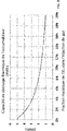
- the stored energy being proportional in the first order to the rise in temperature, less energy will be stored in the tank 1 in the presence of incondensable gases. This reduction in energy due to a lower partial pressure of the vapor is illustrated in figures 2 and 3 corresponding to example 1.
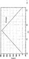
- the decrease in stored energy is all the more marked as the fraction of incondensable gas is high, as illustrated in figure 8 .
- the present invention proposes that during the charging phase, the presence of incondensable gas be compensated by management of the pressure of the gas head 3 to reduce the partial pressure of incondensable gas in favor of the partial pressure of vapor.
- the charging phase comprises, in addition to the injection of a gas at a first flow rate into the tank 1 of the accumulator, a gas evacuation at a second flow from the gas sky 3.
- the charging phase therefore comprises an injection of gas at a first gas flow rate.
- the injected gas comprises a fraction of incondensable gas.
- the gas injected is a mixture of steam, preferably steam, and at least one incondensable gas.
- the gas is injected by a gas injection device 5.
- the gas is preferably injected continuously throughout the charging phase at a first gas flow rate which can be stable or variable.
- the method also comprises an evacuation, which can also be referred to as extraction of gas advantageously from the gas overhead 3.
- the evacuation of gas during the charging phase is carried out by the gas evacuation pipe 4 also used for the evacuation of gas during the discharge phase, as illustrated in figures 1A and 1B .
- the evacuation of gas during the charging phase is done by an evacuation 14, preferably provided with a discharge valve 13.
- the evacuation of gas during the discharge phase is carried out by the pipe of different evacuation 4 as illustrated in figure 1C .
- the evacuation device comprises a gas evacuation 14 separate from the evacuation pipe 4 used for the discharge phase. This second possibility makes it possible in particular to adapt the evacuation to the flow rate evacuated.
- the evacuated flow rate is lower than that evacuated in the discharge phase so that the diameters of the evacuation pipe 4 and of the evacuation 14 are thus adapted.
- the evacuated gas corresponds to the gas from the gas headspace 3.
- the evacuated gas comprises a fraction of incondensable gas.
- the evacuated gas is a mixture of steam, preferably water vapor, and at least one incondensable gas.
- the gas is evacuated continuously or intermittently at a second gas flow which can be stable or variable during the charging phase.
- the second gas flow is advantageously lower than the first gas flow so as to allow the charging of the accumulator, that is to say the increase of the pressure in the tank 1 and therefore of the stored energy.
- the second gas flow represents from 2% to 50% of the first gas flow.
- the gas is evacuated from the gas head 3.
- the second gas flow is advantageously controlled by the control unit and in particular an evacuation valve 7.
- the gas is evacuated throughout the charging phase at a stable or variable rate, the gas evacuation is continuous.
- the gas is evacuated intermittently during the charging phase, i.e. that at least one degassing, preferably successive degassings take place.
- the second gas flow is then either identical during all the degassings, or different.
- the injection of gas at a first flow rate comprises a main flow rate and a complementary gas flow rate.
- the first gas flow is the sum of the main flow and the complementary gas flow.
- the injection of gas at the main flow is advantageously continuous during the charging phase and carried out in the liquid 2.
- the injection of gas at the complementary flow can be continuous during the charging phase or else be intermittent.
- the injection of gas at the complementary flow is intended to compensate at least in part for the evacuation of gas.
- the additional flow increases the flow of gas injected with respect to an accumulator of the state of the art providing a charging phase without evacuation of gas.
- the additional flow may be stable or variable during charging.
- the injection of gas at the complementary flow rate is carried out by the injection device 5.
- the injection of gas at the complementary flow is carried out in the liquid 2.
- the injection of gas at the flow of complementary gas is preferably carried out by the same injection device 5 as the injection of gas at the main flow c i.e. for example the injection line illustrated in Figure 1A . It may be necessary to oversize the injection device 5.
- the valve 8 provides control of the injection and advantageously also of the first gas flow injected.
- the injection device 5 comprises an injector 10 for the injection of gas at the main flow rate and a complementary injector 11 for the injection of gas at the complementary flow rate.
- the additional injector 11 is arranged in the tank 1 immersed in the liquid 2 preferably in the lower part.
- the complementary injection 11 comprises a complementary valve 12 controlling the injection of complementary gas and advantageously the flow rate of complementary gas.
- the injection of gas at the complementary flow rate is carried out in the gas head 3.
- the injection of gas at the complementary gas flow rate is preferably carried out by the injection device 5 comprising an injector 10 for the injection of gas at the main flow and a complementary injector 11 for injecting gas at the complementary flow.
- the additional injector 11 is arranged in the tank in the gas head 3.
- the additional injection 11 comprises an additional valve 12 controls the injection of additional gas and advantageously the flow rate of complementary gas.
- the injection of gas is continuous at a first main flow rate which can be stable or variable during the charging phase.
- Gas injection is continuous at the first additional flow rate which may be stable or variable during the charging phase.
- the gas evacuation is continuous at the second rate which can be stable or variable.
- the injection of gas is continuous at the first main gas flow rate which can be stable or variable during the charging phase.
- Gas injection is intermittent at the first additional flow rate which may be stable or variable during the charging phase.
- Gas evacuation is continuous at the second flow rate which may be stable or variable during the charging phase.
- the injection of gas at the complementary flow rate and the evacuation of gas at the second flow rate can be carried out alternately or simultaneously, without being dependent on one another.
- the method according to the invention is intended to control the first gas flow and the second gas flow as a function of the mass fraction of incondensable gas to achieve optimum energy storage.
- the management module controls the first gas flow and the second gas flow as a function of the fraction of incondensable gas, preferentially also of the maximum target pressure and the minimum target pressure of the accumulator, preferentially also the pressure measured by the pressure measuring device, preferably also the desired charging time.
- the gas extracted by the evacuation device during the charging phase can be upgraded by being for example reinjected into a step of a process for using the gas.
- the present invention finds particular application in the field of deep geothermal energy in which the aim is to recover the energy from brine (highly mineralized water), taken underground, by supplying heating networks and producing electricity, for example.
- brine highly mineralized water
- the quantity of incondensable gases in the brine is not negligible, with for example a mass fraction of incondensable gas between 2% and 20% depending on the geothermal site.
- the following table shows the evolution of the first flow corresponding to the injection of gas and that of the second flow corresponding to the extraction of gas during the load according to the content of CO2, incondensable gas, to store 3.71 MWh in 4h. If the mass fraction of CO2 increases, the first flow and the second flow increase in order to store the same energy (Table 1). Mass fraction of input CO2 [%] Mass flow (steam+CO 2 ) inlet - load [kg/s] Mass flow (steam+CO 2 ) out (extract) - load [kg/s] % exit 2.8 0.46 0.0253 5.5 5 0.53 0.0901 17 10 0.7 0.266 38
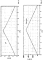
- Example 1 Evolution of pressure and energy in a steam accumulator without incondensable gases.
- an energy of 5 MWh can be stored in 4 hours with a charge rate of 0.58 kg/s, between 4.5 bar absolute and 7.5 bar absolute, c i.e. between 50.5 and 94 relative psi ( Figures 2 and 3 ), under conditions of thermodynamic equilibrium between the two liquid and vapor phases.
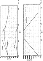
- Example 2 Evolution of pressure and energy in a steam accumulator with incondensable gases.
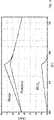
- the stored energy is greatly reduced ( Figure 5 ) compared to example 1.
- it is reduced to 3.34MWh, i.e. -33% less than in example 1.
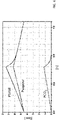
- Example 3 Evolution of pressure and energy in a steam accumulator with incondensable gases.
- Example 2 The same experiment as example 2 is carried out with an injected gas comprising steam and a mass fraction of 2.8% of incondensable gases.
- the gas flow injected is adapted to maintain a charging time of 4 hours.
- the incoming steam flow is reduced from 0.58 kg/s to 0.39 kg/s (i.e. less 33% than in examples 1 and 2) while maintaining the same conditions as in example 1, the load s then stops after 4 hours, and the same amount of energy is stored as in example 2 (3.34MWh) ( Figure 6 and 7 ).
- Example 4 Evolution of the pressure and of the energy in a steam accumulator with incondensable gases according to the method of the invention.
- the storage capacity is therefore increased from 3.34MWh to 3.71MWh, i.e. an 11% increase compared to example 2 or 3.
- the invention is not limited to the embodiments described above and extends to all the embodiments covered by the invention.
Abstract
L'invention concerne un procédé de stockage d'énergie thermique dans un accumulateur de vapeur comprenant une cuve (1) contenant un liquide (2) et un ciel de gaz (3) agencé au-dessus du liquide ((2), un dispositif d'injection (5) de gaz entrant dans la cuve (1) et un dispositif d'évacuation (4) de gaz sortant de la cuve (1), le gaz comprenant de la vapeur et au moins un gaz incondensable, le procédé comprenant une phase de charge d'énergie comprenant une injection de gaz à un premier débit de gaz dans la cuve (1) de l'accumulateur par le dispositif d'injection (5) de gaz caractérisé en ce que le procédé comprend en outre pendant la phase de charge d'énergie une évacuation de gaz à un deuxième débit de gaz hors de la cuve (1) de l'accumulateur par le dispositif d'évacuation (4) de gaz.La présente invention concerne le domaine des accumulateurs de vapeur. Elle trouve pour application particulièrement avantageuse le stockage d'énergie dans un accumulateur de vapeur par condensation directe en particulier lorsque le gaz stocké comprend des gaz incondensables tels que par exemple dans le cas de la géothermie ou encore les centrales thermodynamiques de production d'électricité.The invention relates to a method for storing thermal energy in a steam accumulator comprising a tank (1) containing a liquid (2) and a gas head (3) arranged above the liquid ((2), a device for injecting (5) gas entering the tank (1) and a device (4) for evacuating gas leaving the tank (1), the gas comprising steam and at least one incondensable gas, the method comprising an energy charging phase comprising an injection of gas at a first gas flow into the tank (1) of the accumulator by the gas injection device (5) characterized in that the method further comprises during the energy charging phase an evacuation of gas at a second gas flow rate out of the tank (1) of the accumulator by the gas evacuation device (4). The present invention relates to the field of steam accumulators. It finds for particularly advantageous application the storage of energy in a steam accumulator by direct condensation. e in particular when the stored gas comprises incondensable gases such as for example in the case of geothermal energy or even thermodynamic electricity production plants.
Description
La présente invention concerne le domaine des accumulateurs de vapeur. Elle trouve pour application particulièrement avantageuse le stockage d'énergie dans un accumulateur de vapeur par condensation directe en particulier lorsque le gaz stocké comprend des gaz incondensables tels que par exemple dans le cas de la géothermie ou encore les centrales thermodynamiques de production d'électricité.The present invention relates to the field of steam accumulators. It finds a particularly advantageous application in the storage of energy in a steam accumulator by direct condensation, in particular when the stored gas comprises incondensable gases such as, for example, in the case of geothermal energy or even thermodynamic power stations for the production of electricity.
La vapeur d'eau est l'un des fluides caloporteurs utilisés fréquemment dans l'industrie. Elle a pour avantage de pouvoir transporter une grande quantité de chaleur par unité de masse : car elle la transporte en grande partie sous forme de chaleur latente, par sa transition de phase liquide - vapeur. Ce fluide caloporteur permet par exemple de produire de l'électricité dans les centrales thermodynamiques.Water vapor is one of the heat transfer fluids frequently used in industry. It has the advantage of being able to transport a large quantity of heat per unit mass: because it transports it largely in the form of latent heat, through its liquid-vapor phase transition. This heat transfer fluid is used, for example, to produce electricity in thermodynamic power stations.
Le stockage de la vapeur dans l'industrie a pour but de stocker l'énergie de la vapeur aux périodes où celle-ci n'est pas nécessaire et de la restituer aux moments où un procédé en a besoin. Le stockage thermique permet ainsi de déphaser la production de vapeur et son utilisation. Le stockage thermique peut également permettre de stabiliser la fourniture de vapeur à un procédé en lissant les fluctuations liées à la production.The purpose of steam storage in industry is to store steam energy when it is not needed and to release it when a process needs it. Thermal storage thus makes it possible to phase-shift the production of steam and its use. Thermal storage can also help stabilize the supply of steam to a process by smoothing out production-related fluctuations.
Dans les secteurs de production d'énergie électrique renouvelable, le stockage de vapeur permet de stocker l'énergie thermique pendant les périodes où la demande en électricité est faible afin de la restituer pendant les pics de consommation électrique dans le but de limiter le recours à des moyens d'appoint fossiles.In the renewable electricity production sectors, steam storage makes it possible to store thermal energy during periods when electricity demand is low in order to restore it during peak electricity consumption with the aim of limiting the use of fossil booster means.
Il existe plusieurs façons de stocker de la vapeur notamment par condensation directe, par exemple en la stockant dans des réservoirs d'eau liquide sous pression dénommés accumulateurs de vapeur.There are several ways of storing steam, in particular by direct condensation, for example by storing it in pressurized liquid water tanks called steam accumulators.
Dans plusieurs applications industrielles telles que les centrales thermodynamiques de production d'électricité à partir d'énergie en provenance de la géothermie, la vapeur peut contenir des gaz incondensables tels que du dioxyde de carbone (CO2). L'utilisation d'un accumulateur de vapeur dans ce type d'application est donc classiquement évitée.In several industrial applications such as thermodynamic power plants producing electricity from energy coming from geothermal energy, the steam can contain incondensable gases such as carbon dioxide (CO2). The use of a steam accumulator in this type of application is therefore conventionally avoided.
En effet, la cuve de l'accumulateur étant fermée, sa capacité de stockage diminue fortement, car les gaz incondensables transportés par la vapeur d'eau injectée s'accumulent dans le ciel du réservoir pendant la phase de charge. La pression partielle de gaz incondensables augmente rapidement au cours de la phase de charge au détriment de la pression partielle de vapeur. Cette dernière est alors inférieure à la pression totale de fin de charge qui est une donnée du système. La présence de gaz incondensable se traduit donc par une diminution de la capacité de stockage du réservoir.Indeed, since the accumulator tank is closed, its storage capacity decreases sharply, because the incondensable gases transported by the injected water vapor accumulate in the top of the tank during the charging phase. The partial pressure of incondensable gases increases rapidly during the charging phase to the detriment of the partial pressure of vapor. The latter is then less than the total end-of-charge pressure which is system data. The presence of incondensable gas therefore results in a reduction in the storage capacity of the tank.
La présente invention a pour but de proposer une solution qui permet de limiter l'impact des gaz incondensables sur la capacité de stockage d'un accumulateur de vapeur.The aim of the present invention is to propose a solution which makes it possible to limit the impact of incondensable gases on the storage capacity of a vapor accumulator.
Les autres objets, caractéristiques et avantages de la présente invention apparaîtront à l'examen de la description suivante et des dessins d'accompagnement. Il est entendu que d'autres avantages peuvent être incorporés.The other objects, features and advantages of the present invention will become apparent from a review of the following description and the accompanying drawings. It is understood that other benefits may be incorporated.
Pour atteindre cet objectif, l'invention prévoit un procédé de stockage d'énergie thermique dans un accumulateur de vapeur comprenant une cuve, avantageusement fermée, préférentiellement étanche sous pression, contenant un liquide et un ciel de gaz agencé au-dessus du liquide, un dispositif d'injection de gaz entrant dans la cuve et un dispositif d'évacuation de gaz sortant de la cuve, le gaz comprenant de la vapeur et au moins un gaz incondensable, le procédé comprenant une phase de charge d'énergie comprenant une injection de gaz à un premier débit de gaz dans la cuve de l'accumulateur par le dispositif d'injection de gaz caractérisé en ce que le procédé comprend en outre pendant la phase de charge d'énergie une évacuation de gaz à un deuxième débit de gaz hors de la cuve de l'accumulateur par le dispositif d'évacuation de gaz.To achieve this objective, the invention provides a method for storing thermal energy in a vapor accumulator comprising a tank, advantageously closed, preferably leaktight under pressure, containing a liquid and a gas sky arranged above the liquid, a device for injecting gas entering the tank and a device for evacuating gas leaving the tank, the gas comprising steam and at least one incondensable gas, the method comprising an energy charging phase comprising an injection of gas at a first gas flow rate in the tank of the accumulator by the gas injection device characterized in that the method further comprises during the energy charging phase a gas evacuation at a second gas flow rate outside from the accumulator tank via the gas evacuation device.
Le procédé selon l'invention permet ainsi de limiter la pression partielle de gaz incondensable dans la cuve et plus spécifiquement dans le ciel de gaz situé au-dessus du liquide contenu dans la cuve. Or, la pression partielle de gaz dans la cuve est classiquement le paramètre limitant la capacité énergétique de l'accumulateur, car la pression partielle de gaz limite la pression partielle de vapeur pour une pression totale de gaz fixée. La capacité de stockage d'un accumulateur de vapeur est donc optimisée par le présent procédé. La présente invention permet d'appliquer le procédé de stockage à des systèmes de stockage thermique de type accumulateur de vapeur existante. L'invention permet d'augmenter la capacité de stockage sans augmenter la taille de l'accumulateur ni la pression maximale de fonctionnement du stockage.The method according to the invention thus makes it possible to limit the partial pressure of incondensable gas in the tank and more specifically in the gas head located above the liquid contained in the tank. However, the partial pressure of gas in the tank is conventionally the parameter limiting the energy capacity of the accumulator, since the partial pressure of gas limits the partial pressure of vapor for a fixed total pressure of gas. The storage capacity of a vapor accumulator is therefore optimized by the present method. The present invention makes it possible to apply the storage method to thermal storage systems of the existing vapor accumulator type. The invention makes it possible to increase the storage capacity without increasing the size of the accumulator or the maximum operating pressure of the storage.
En diminuant la fraction de gaz incondensables dans le ciel de gaz de la cuve, la capacité de stockage augmente. La même quantité d'énergie pourra donc être stockée dans un accumulateur de plus petit volume, ce qui permet de réduire le coût de l'installation ou bien pour un même volume d'accumulateur, une plus grande quantité d'énergie sera stockée, ce qui permet d'avoir une installation plus rentable.By decreasing the fraction of incondensable gases in the gas overhead of the vessel, the storage capacity increases. The same quantity of energy can therefore be stored in an accumulator of smaller volume, which makes it possible to reduce the cost of the installation or else for the same volume of accumulator, a greater quantity of energy will be stored, which allows for a more profitable installation.
Un autre aspect concerne un accumulateur de vapeur comprenant une cuve, avantageusement fermée, préférentiellement étanche sous pression, contenant un liquide et un ciel de gaz, un dispositif d'injection de gaz entrant dans la cuve, un dispositif d'évacuation de gaz sortant de la cuve, un module de gestion comprenant un ordinateur et une unité de contrôle comprenant des vannes de contrôles du dispositif d'injection de gaz et du dispositif d'évacuation de gaz sortant de la cuve caractérisé en ce que le module de gestion est configuré pour mettre en œuvre les actions suivantes pendant la phase de charge d'énergie:
- a. une injection de gaz à un premier débit de gaz dans la cuve de l'accumulateur par le dispositif d'injection de gaz
- b. une évacuation de gaz à un deuxième débit de gaz hors de la cuve de l'accumulateur par le dispositif d'évacuation de gaz.
- has. injection of gas at a first gas flow into the cell of the accumulator by the gas injection device
- b. a gas evacuation at a second gas flow out of the tank of the accumulator by the gas evacuation device.
Les buts, objets, ainsi que les caractéristiques et avantages de l'invention ressortiront mieux de la description détaillée d'un mode de réalisation de cette dernière qui est illustré par les dessins d'accompagnement suivants dans lesquels :
- Les
figures 1A à 1C représentent un schéma d'un accumulateur de vapeur selon l'invention. Lafigure 1A représente l'accumulateur selon une première possibilité. Lafigure 1B représente l'accumulateur selon une deuxième possibilité. Lafigure 1C représente l'accumulateur selon une troisième possibilité. - La
figure 2 représente l'évolution de la pression dans un accumulateur de vapeur sans gaz incondensable selon l'exemple 1. - La
figure 3 représente l'évolution de l'énergie dans un accumulateur de vapeur sans gaz incondensable selon l'exemple 1. - La
figure 4 représente l'évolution de la pression (partielle de vapeur, partielle de gaz et totale) dans un accumulateur de vapeur avec une fraction massique de 2,8% de gaz incondensables selon l'exemple 2. - La
figure 5 représente l'évolution de l'énergie dans un accumulateur de vapeur avec une fraction massique de 2,8% de gaz incondensables selon l'exemple 2. - La
figure 6 représente l'évolution de la pression (partielle de vapeur, partielle de gaz et totale) dans un accumulateur de vapeur avec une fraction massique de 2,8% de gaz incondensables selon l'exemple 3 avec un débit de gaz injecté plus faible qu'à l'exemple 2. - La
figure 7 représente l'évolution de l'énergie dans un accumulateur de vapeur avec une fraction massique de 2,8% de gaz incondensables selon l'exemple 3 avec un débit de gaz injecté plus faible qu'à l'exemple 2. - La
figure 8 représente l'évolution de la capacité de stockage d'un accumulateur de vapeur en fonction de la fraction massique du CO2 dans le gaz. - La
figure 9 représente l'évolution de la pression dans un accumulateur de vapeur avec une fraction massique de 2,8% de gaz incondensables dans la vapeur selon un exemple de l'invention illustré enexemple 4. - La
figure 10 représente l'évolution de l'énergie dans un accumulateur de vapeur avec une fraction massique de 2,8% de gaz incondensables dans la vapeur selon un exemple de l'invention illustré enexemple 4.
- The
figures 1A to 1C show a diagram of a steam accumulator according to the invention. TheFigure 1A represents the accumulator according to a first possibility. Thefigure 1B represents the accumulator according to a second possibility. Thefigure 1C represents the accumulator according to a third possibility. - The
picture 2 - The
picture 3 - The
figure 4 represents the evolution of the pressure (partial vapor, partial gas and total) in a vapor accumulator with a mass fraction of 2.8% of incondensable gases according to example 2. - The
figure 5 represents the evolution of energy in a steam accumulator with a mass fraction of 2.8% of incondensable gases according to example 2. - The
figure 6 represents the evolution of the pressure (partial steam, partial gas and total) in a steam accumulator with a mass fraction of 2.8% of incondensable gases according to example 3 with a gas flow rate injected lower than to example 2. - The
figure 7 represents the evolution of energy in a steam accumulator with a mass fraction of 2.8% of incondensable gases according to Example 3 with a gas flow rate injected lower than in Example 2. - The
figure 8 represents the evolution of the storage capacity of a steam accumulator as a function of the mass fraction of CO2 in the gas. - The
figure 9 represents the evolution of the pressure in a steam accumulator with a mass fraction of 2.8% of incondensable gases in the steam according to an example of the invention illustrated in example 4. - The
figure 10 represents the evolution of the energy in a steam accumulator with a mass fraction of 2.8% of incondensable gases in the steam according to an example of the invention illustrated in example 4.
Les dessins sont donnés à titre d'exemples et ne sont pas limitatifs de l'invention. Ils constituent des représentations schématiques de principe destinées à faciliter la compréhension de l'invention et ne sont pas nécessairement à l'échelle des applications pratiques.The drawings are given by way of examples and do not limit the invention. They constitute schematic representations of principle intended to facilitate understanding of the invention and are not necessarily at the scale of practical applications.
Avant d'entamer une revue détaillée de modes de réalisation de l'invention, sont énoncées ci-après des caractéristiques optionnelles qui peuvent éventuellement être utilisées en association ou alternativement :
Selon un exemple, l'évacuation de gaz à un deuxième débit de gaz est intermittente au cours de la phase de charge.Before starting a detailed review of embodiments of the invention, optional characteristics are set out below which may possibly be used in combination or alternatively:
According to one example, the evacuation of gas at a second gas flow rate is intermittent during the charging phase.
Selon un exemple, l'évacuation de gaz à un deuxième débit de gaz est continue au cours de la phase de charge. Cette disposition assure une grande facilité de gestion de la phase de charge.According to one example, the evacuation of gas at a second gas flow rate is continuous during the charging phase. This arrangement ensures great ease of management of the charging phase.
Selon un exemple, le deuxième débit de gaz est inférieur au premier débit de gaz. De cette manière, la charge est réalisée tout en limitant la pression partielle de gaz incondensable dans la cuve.According to one example, the second gas flow is lower than the first gas flow. In this way, the load is carried out while limiting the partial pressure of incondensable gas in the tank.
Selon un exemple, l'évacuation de gaz à un deuxième débit de gaz est réalisée depuis le ciel de gaz.According to one example, the evacuation of gas at a second gas flow rate is carried out from the gas overhead.
Selon un exemple, l'injection de gaz à un premier débit de gaz est continue au cours de la phase de charge.According to one example, the injection of gas at a first gas flow rate is continuous during the charging phase.
Selon un exemple, l'injection de gaz à un premier débit de gaz comprend un débit principal de gaz et un débit complémentaire de gaz. Préférentiellement, le premier débit de gaz est constitué d'un débit principal de gaz et d'un débit complémentaire de gaz.According to one example, the injection of gas at a first gas flow comprises a main gas flow and a complementary gas flow. Preferably, the first gas flow consists of a main gas flow and a complementary gas flow.
Selon un exemple, l'injection de gaz à un débit complémentaire de gaz est intermittente au cours de la phase de charge. Selon cette disposition, le premier débit de gaz est continu au cours de la phase de charge, mais le premier débit de gaz est variable, il augmente et diminue en fonction de l'intermittence du débit complémentaire.According to one example, the gas injection at a complementary gas flow rate is intermittent during the charging phase. According to this arrangement, the first gas flow is continuous during the charging phase, but the first gas flow is variable, it increases and decreases depending on the intermittency of the additional flow.
Selon un exemple, l'injection de gaz à un débit complémentaire de gaz est continue au cours de la phase de charge.According to one example, the injection of gas at a complementary gas flow is continuous during the charging phase.
Selon un exemple, l'injection de gaz à un débit complémentaire de gaz est réalisée dans le liquide contenu dans la cuve. Cette disposition permet d'optimiser l'équilibre thermodynamique entre le liquide et le ciel de gaz.According to one example, the injection of gas at a complementary gas flow is carried out in the liquid contained in the tank. This arrangement makes it possible to optimize the thermodynamic balance between the liquid and the headspace of gas.
Selon un exemple, l'injection de gaz à un débit complémentaire de gaz est réalisée dans un ciel de gaz agencé au-dessus du liquide contenu dans la cuve. Dans cette disposition, le ciel de gaz est balayé par le débit complémentaire. Le pilotage de la phase de charge est facilité suivant ce mode de réalisation.According to one example, the injection of gas at a complementary gas flow is carried out in a gas head arranged above the liquid contained in the tank. In this arrangement, the gas overhead is swept by the additional flow. The control of the charging phase is facilitated according to this embodiment.
Selon un exemple, le débit complémentaire de gaz est inférieur au débit principal de gaz. Le débit de gaz complémentaire correspond à compenser au moins partiellement le deuxième débit d'évacuation de gaz de sorte à notamment respecter une consigne de temps de charge identique, quel que soit la fraction de gaz incondensable accompagnant la vapeur dans le gaz.According to one example, the complementary gas flow is lower than the main gas flow. The additional gas flow corresponds to at least partially offset the second gas evacuation flow so as to in particular respect an identical charging time setpoint, regardless of the fraction of incondensable gas accompanying the vapor in the gas.
Selon un exemple, le deuxième débit de gaz est supérieur ou égal au débit complémentaire de gaz.According to one example, the second gas flow is greater than or equal to the complementary gas flow.
Selon un exemple, le liquide contenu dans la cuve est de l'eau et la vapeur du gaz est de la vapeur d'eau comprenant au moins un gaz incondensable.According to one example, the liquid contained in the tank is water and the vapor of the gas is water vapor comprising at least one incondensable gas.
Il est précisé que dans le cadre de la présente invention, le terme débit s'entend comme un débit massique en kg/s.It is specified that in the context of the present invention, the term flow rate is understood as a mass flow rate in kg/s.
La quantité de gaz incondensable dans le gaz comprenant la vapeur est donnée en fraction ou pourcentage massique par rapport à la quantité massique totale de gaz.The quantity of incondensable gas in the gas comprising the vapor is given as a mass fraction or percentage relative to the total mass quantity of gas.
Un accumulateur de vapeur comprend une cuve 1 contenant un liquide 2 et un ciel de gaz 3. La cuve est avantageusement fermée, plus préférentiellement étanche de sorte à maintenir les fluides : le liquide 2 et le ciel de gaz 3, à l'intérieur de la cuve 1. La cuve 1 est avantageusement configurée pour permettre une mise sous pression du liquide 2 et du ciel de gaz 3. La cuve 1 est avantageusement étanche aux gaz et aux liquides.A vapor accumulator comprises a
La cuve 1 comprend un dispositif d'injection de gaz 5 et un dispositif d'évacuation de gaz.The
Le dispositif d'injection de gaz 5 est destiné à injecter dans la cuve 1 un gaz. Préférentiellement, le gaz est de la vapeur par exemple de la vapeur d'eau comprenant au moins un gaz incondensable. L'injection de gaz est au moins partiellement réalisée dans le liquide 2. Selon une possibilité, le dispositif d'injection comprend un injecteur 10 par exemple sous la forme d'une ligne d'injection plongeant dans le liquide 2 de la cuve 1, préférentiellement en partie basse. La ligne d'injection comprend par exemple une pluralité de sortie préférentiellement répartie dans la cuve 1. L'injection de gaz par le dispositif d'injection de gaz 5 se fait à un premier débit de gaz.The
Le dispositif d'évacuation de gaz est destiné à évacuer hors de la cuve 1 le gaz. L'évacuation de gaz est réalisée depuis le ciel de gaz 3. Préférentiellement, le gaz est de la vapeur par exemple de la vapeur d'eau comprenant au moins un gaz indésirable. Selon une possibilité, le dispositif d'évacuation comprend une conduite d'évacuation 4 débouchant à une extrémité dans la cuve 1 et se prolongeant à l'extérieur de la cuve 1. L'évacuation de gaz par le dispositif d'évacuation de gaz se fait à un deuxième débit de gaz.The gas evacuation device is intended to evacuate the gas from the
Selon un mode de réalisation, la cuve 1 comprend un dispositif de remplissage et vidange 6 du liquide 2. Le dispositif de remplissage et de vidange 6 de liquide 2 est utilisé pour remplir ou vider la cuve 1 de liquide 2. Préférentiellement, ce dispositif de remplissage et de vidange 6 est agencé en partie basse de la cuve 1 pour faciliter sa vidange. Selon une possibilité, le dispositif de remplissage et de vidange 6 comprend une vanne 9 assurant l'ouverture et la fermeture du dispositif de remplissage et de vidange 6 permettant de contrôler le remplissage et la vidange de la cuve 1.According to one embodiment, the
L'accumulateur de vapeur comprend selon un mode de réalisation, une unité de commande comprenant des vannes commandées pour contrôler l'injection et l'évacuation de gaz dans et hors de la cuve 1. L'unité de commande comprend avantageusement une vanne d'évacuation 7 agencée sur le dispositif d'évacuation préférentiellement sur la conduite d'évacuation 4. La vanne d'évacuation 7 permet d'initier ou d'arrêter l'évacuation de gaz hors de la cuve 1. Préférentiellement, la vanne d'évacuation 7 est configurée pour contrôler le deuxième débit c'est-à-dire le débit d'évacuation de gaz.The steam accumulator comprises according to one embodiment, a control unit comprising valves controlled to control the injection and evacuation of gas into and out of the
L'unité de commande comprend avantageusement une vanne d'injection 8 agencée sur le dispositif d'injection 5 préférentiellement sur la ligne d'injection. La vanne d'injection 8 permet d'initier ou d'arrêter l'injection de gaz dans la cuve 1. Préférentiellement, la vanne d'injection 8 est configurée pour contrôler le premier débit c'est-à-dire le débit d'injection de gaz.The control unit advantageously comprises an
L'accumulateur comprend selon une possibilité au moins un dispositif de mesure notamment de paramètres de fonctionnement de l'accumulateur. Au moins un dispositif de mesure est un capteur de pression de la pression total dans la cuve 1.The accumulator comprises, according to one possibility, at least one device for measuring in particular the operating parameters of the accumulator. At least one device measurement is a pressure sensor of the total pressure in
L'accumulateur de vapeur comprend selon un mode de réalisation un module de gestion. Le module de gestion est destiné à optimiser la capacité de stockage de l'accumulateur en fonction de la fraction massique de gaz incondensable dans la vapeur du gaz stocké.The steam accumulator comprises according to one embodiment a management module. The management module is intended to optimize the storage capacity of the accumulator according to the mass fraction of incondensable gas in the vapor of the stored gas.
Le module de gestion comprend préférentiellement des moyens informatiques traditionnels, notamment un processeur, une mémoire, et un programme d'ordinateur stocké dans la mémoire et comprenant une série d'instructions configurée pour traiter des données d'entrée, notamment reçues de dispositifs de mesure ou des données de l'accumulateur.The management module preferably comprises traditional computer means, in particular a processor, a memory, and a computer program stored in the memory and comprising a series of instructions configured to process input data, in particular received from measurement devices or accumulator data.
L'invention concerne avantageusement le stockage thermique sous forme de vapeur par condensation directe. La vapeur est accumulée dans la cuve 1 contenant un liquide 2 sous pression.The invention advantageously relates to thermal storage in the form of vapor by direct condensation. The steam is accumulated in the
Selon un mode de réalisation préféré, le liquide 2 contenu dans la cuve 1 est de l'eau à l'état liquide tandis que le gaz comprend de la vapeur telle que de la vapeur d'eau et au moins un gaz incondensable.According to a preferred embodiment, the
Un accumulateur de vapeur selon l'invention fonctionne pour mettre en oeuvre un procédé de stockage d'énergie thermique. Le procédé de stockage d'énergie thermique comprend une phase de charge au cours de laquelle l'énergie thermique est stockée dans l'accumulateur. Le procédé comprend avantageusement une phase de décharge au cours de laquelle l'énergie thermique est déstockée de l'accumulateur.A steam accumulator according to the invention operates to implement a thermal energy storage method. The thermal energy storage method comprises a charging phase during which the thermal energy is stored in the accumulator. The method advantageously comprises a discharge phase during which the thermal energy is destocked from the accumulator.
Dans la présente description, on entend par gaz un mélange de gaz comprenant de la vapeur telle que de la vapeur d'eau et au moins un gaz incondensable.In the present description, by gas is meant a mixture of gases comprising steam such as water vapor and at least one incondensable gas.
On entend par gaz incondensable, un gaz qui ne peut être condensé dans les conditions d'utilisation de l'accumulateur de vapeur. Les gaz incondensables sont par exemple du dioxyde de carbone CO2 ou encore H2S, N2, CH4, Ar, O2, H2, He, C2H6, C3H8. Dans plusieurs applications industrielles telles que les centrales thermodynamiques de production d'électricité sur des sites géothermiques, la vapeur peut contenir des gaz incondensables.By incondensable gas is meant a gas which cannot be condensed under the conditions of use of the vapor accumulator. The incondensable gases are, for example, carbon dioxide CO2 or else H2S, N2, CH4, Ar, O2, H2, He, C2H6, C3H8. In several industrial applications such as thermodynamic power plants for the production of electricity on geothermal sites, the steam can contain incondensable gases.
Le principe d'une phase de charge et d'une phase de décharge d'un accumulateur de vapeur est décrit ci-après.The principle of a charging phase and a discharging phase of a vapor accumulator is described below.
La phase de charge permet de stocker l'énergie thermique sous forme de vapeur.The charging phase enables thermal energy to be stored in the form of vapour.
Au début de la phase de charge, la cuve 1 contient une quantité de liquide 2 à saturation et un ciel de gaz 3 saturé à la pression minimale de fonctionnement. La vanne de décharge 7 est fermée.At the start of the charging phase,
Un gaz à une pression plus élevée que la pression dans la cuve 1 est injecté, préférentiellement par le bas de la cuve 1, à travers le dispositif d'injection 5. Préférentiellement, la vanne de charge 8 est ouverte. Les bulles de vapeur se condensent au contact du liquide 2 plus froid et libèrent de l'énergie, ce qui augmente la température du liquide 2. Si le liquide 2 et le ciel de gaz 3 sont à l'équilibre thermodynamique, cette augmentation de la température se traduit par une augmentation de la pression dans la cuve 1 par évaporation du liquide 2 à sa surface libre. Si l'épaisseur de liquide 2 est insuffisante pour assurer la condensation de toute la vapeur au contact du liquide 2, l'augmentation de pression dans la cuve 1 est liée à l'accumulation de vapeur dans le ciel de gaz 3. Cette vapeur en surpression par rapport à la pression de saturation, se condense à la surface libre du liquide 2 pour tendre vers l'équilibre thermodynamique. La surface libre du liquide s'entend comme la surface du liquide 2 à l'interface avec le ciel de gaz 3.A gas at a pressure higher than the pressure in
Le niveau de liquide 2 augmente aussi, résultat de la condensation de la vapeur injectée.The level of
Pendant cette phase de charge, la pression dans la cuve 1 augmente, selon une possibilité en continu. Selon un mode de réalisation, le stockage s'arrête quand la pression atteint une pression maximale cible. Selon une possibilité, la pression cible est la pression du dispositif d'injection 5, plus précisément la pression maximale du gaz injecté.During this charging phase, the pressure in
Le niveau de liquide et la pression sont maximaux à la fin de la phase de charge.The liquid level and the pressure are maximum at the end of the charging phase.
La phase de décharge est décrite ci-après. La phase de décharge est destinée à permettre de fournir de l'énergie thermique sous forme de vapeur à une source finale. Par exemple, la source finale peut être une turbine à vapeur.The discharge phase is described below. The discharge phase is intended to make it possible to supply thermal energy in the form of vapor to a final source. For example, the final source may be a steam turbine.
Pendant la phase de décharge, le dispositif d'injection 5 est fermé, préférentiellement la vanne de charge 8 est fermée. La vanne de décharge 7 est ouverte.During the discharge phase, the
Lors de l'ouverture du dispositif d'évacuation, la pression dans la cuve 1 diminue provoquant une vaporisation du liquide 2. En effet, le liquide 2 se retrouve à une température très légèrement supérieure à la température de saturation, entrainant une vaporisation rapide du liquide 2. Cette vaporisation nécessite de l'énergie, chaleur latente de vaporisation, qui est fournie par le liquide 2. La température du liquide 2 diminue en conséquence. Le niveau de liquide 2 diminue pendant cette phase de décharge, car une partie de liquide 2 est évaporée. L'accumulateur produit de la vapeur saturée.When the evacuation device is opened, the pressure in
Cette phase de décharge s'arrête quand la cuve 1 atteint une pression minimale cible. Préférentiellement, la pression minimale cible est fonction de la pression minimale acceptée par la source finale.This discharge phase stops when
Il peut arriver qu'il y ait un déséquilibre thermodynamique avec une pression plus élevée que la pression d'équilibre à la charge et une pression moins élevée à la décharge. L'hypothèse d'équilibre thermodynamique est donc favorable. Le déséquilibre est défavorable en interrompant plus tôt la charge et la décharge.It can happen that there is a thermodynamic imbalance with a pressure higher than the equilibrium pressure at the load and a lower pressure at the discharge. The hypothesis of thermodynamic equilibrium is therefore favourable. The unbalance is unfavorable by interrupting charging and discharging earlier.
Selon l'invention, le gaz injecté dans l'accumulateur comprend au moins un gaz incondensable. La présence de ces derniers dans la vapeur a un impact important sur la capacité de stockage d'un accumulateur de vapeur.According to the invention, the gas injected into the accumulator comprises at least one incondensable gas. The presence of these in the steam has a significant impact on the storage capacity of a steam accumulator.
La cuve est fermée, sa capacité de stockage diminue fortement, car les gaz incondensables transportés par la vapeur injectée s'accumulent dans le ciel du gaz 3 pendant la phase de charge. La pression partielle de gaz incondensables augmente au cours de la phase de charge au détriment de la pression partielle de vapeur. Cette dernière est alors inférieure à la pression maximale cible également dénommée pression totale de fin de charge qui est une valeur prédéfinie. Or, la température du liquide suit la pression de la vapeur. La température finale du liquide 2 dans la cuve 1 sera donc inférieure à celle qu'elle aurait eue en absence de gaz incondensable. L'énergie stockée étant proportionnelle en premier ordre à l'élévation de température, moins d'énergie sera stockée dans la cuve 1 en présence de gaz incondensables. Cette diminution de l'énergie du fait d'une moindre pression partielle de la vapeur est illustrée aux
La diminution de l'énergie stockée est d'autant plus marquée que la fraction de gaz incondensable est élevée, comme illustré à la
La présente invention propose que lors de la phase de charge, la présence de gaz incondensable soit compensée par une gestion de la pression du ciel de gaz 3 pour réduire la pression partielle de gaz incondensable au profit de la pression partielle de vapeur.The present invention proposes that during the charging phase, the presence of incondensable gas be compensated by management of the pressure of the
À cet effet, la phase de charge comprend en plus de l'injection d'un gaz à un premier débit dans la cuve 1 de l'accumulateur une évacuation de gaz à un deuxième débit depuis le ciel de gaz 3.To this end, the charging phase comprises, in addition to the injection of a gas at a first flow rate into the
La phase de charge comprend donc une injection de gaz à un premier débit de gaz. Le gaz injecté comprend une fraction de gaz incondensable. Préférentiellement, le gaz injecté est un mélange de vapeur, préférentiellement de vapeur d'eau, et d'au moins un gaz incondensable. Le gaz est injecté par un dispositif d'injection de gaz 5. Le gaz est injecté préférentiellement de manière continue pendant toute la phase de charge à un premier débit de gaz qui peut être stable ou variable.The charging phase therefore comprises an injection of gas at a first gas flow rate. The injected gas comprises a fraction of incondensable gas. Preferably, the gas injected is a mixture of steam, preferably steam, and at least one incondensable gas. The gas is injected by a
Au cours de la phase de charge, le procédé comprend également une évacuation, pouvant être aussi dénommée extraction de gaz avantageusement depuis le ciel de gaz 3. Selon une première possibilité, l'évacuation de gaz au cours de la phase de charge est réalisée par la conduite d'évacuation de gaz 4 également utilisé pour l'évacuation de gaz lors de la phase de décharge, tel qu'illustré aux
Le gaz est évacué de manière continue ou intermittente à un deuxième débit de gaz qui peut être stable ou variable au cours de la phase de charge.The gas is evacuated continuously or intermittently at a second gas flow which can be stable or variable during the charging phase.
Le deuxième débit de gaz est avantageusement inférieur au premier débit de gaz de sorte à permettre la charge de l'accumulateur c'est-à-dire l'augmentation de la pression dans la cuve 1 et donc de l'énergie stockée. À titre d'exemple, le deuxième débit de gaz représente de 2% à 50% du premier débit de gaz.The second gas flow is advantageously lower than the first gas flow so as to allow the charging of the accumulator, that is to say the increase of the pressure in the
Le gaz est évacué depuis le ciel de gaz 3. Le deuxième débit de gaz est avantageusement contrôlé par l'unité de commande et notamment une vanne d'évacuation 7.The gas is evacuated from the
Selon une possibilité, le gaz est évacué pendant toute la phase de charge à un débit stable ou variable, l'évacuation de gaz est continue. Selon une autre possibilité, le gaz est évacué de manière intermittente au cours de la phase de charge, c'est à dire qu'au moins un dégazage, préférentiellement des dégazages successifs ont lieu. Le deuxième débit de gaz est alors soit identique lors de tous les dégazages, soit différent.According to one possibility, the gas is evacuated throughout the charging phase at a stable or variable rate, the gas evacuation is continuous. Alternatively, the gas is evacuated intermittently during the charging phase, i.e. that at least one degassing, preferably successive degassings take place. The second gas flow is then either identical during all the degassings, or different.
Selon un mode de réalisation, l'injection de gaz à un premier débit comprend un débit principal et un débit complémentaire de gaz.According to one embodiment, the injection of gas at a first flow rate comprises a main flow rate and a complementary gas flow rate.
Le premier débit de gaz est la somme du débit principal et du débit complémentaire de gaz.The first gas flow is the sum of the main flow and the complementary gas flow.
L'injection de gaz au débit principal est avantageusement continue pendant la phase de charge et réalisée dans le liquide 2.The injection of gas at the main flow is advantageously continuous during the charging phase and carried out in the
L'injection de gaz au débit complémentaire peut être continue pendant la phase de charge ou bien être intermittente. L'injection de gaz au débit complémentaire est destinée à compenser au moins en partie l'évacuation de gaz. Le débit complémentaire augmente le débit de gaz injecté par rapport à un accumulateur de l'état de la technique assurant une phase de charge sans évacuation de gaz. Le débit complémentaire peut être stable ou bien variable au cours de la charge.The injection of gas at the complementary flow can be continuous during the charging phase or else be intermittent. The injection of gas at the complementary flow is intended to compensate at least in part for the evacuation of gas. The additional flow increases the flow of gas injected with respect to an accumulator of the state of the art providing a charging phase without evacuation of gas. The additional flow may be stable or variable during charging.
Avantageusement, l'injection de gaz au débit complémentaire est réalisée par le dispositif d'injection 5.Advantageously, the injection of gas at the complementary flow rate is carried out by the
Selon une première possibilité illustrée à la
Selon une deuxième possibilité illustrée à la
Selon un premier mode de réalisation, l'injection de gaz est continue à un premier débit principal qui peut être stable ou variable au cours de la phase de charge. L'injection de gaz est continue au premier débit complémentaire qui peut être stable ou variable au cours de la phase de charge. L'évacuation de gaz est continue au deuxième débit qui peut être stable ou variable.According to a first embodiment, the injection of gas is continuous at a first main flow rate which can be stable or variable during the charging phase. Gas injection is continuous at the first additional flow rate which may be stable or variable during the charging phase. The gas evacuation is continuous at the second rate which can be stable or variable.
Selon un deuxième mode de réalisation, l'injection de gaz est continue au premier débit de gaz principal qui peut être stable ou variable au cours de la phase de charge. L'injection de gaz est intermittente au premier débit complémentaire qui peut être stable ou variable au cours de la phase de charge. L'évacuation de gaz est continue au deuxième débit qui peut être stable ou variable au cours de la phase de charge.According to a second embodiment, the injection of gas is continuous at the first main gas flow rate which can be stable or variable during the charging phase. Gas injection is intermittent at the first additional flow rate which may be stable or variable during the charging phase. Gas evacuation is continuous at the second flow rate which may be stable or variable during the charging phase.
Selon un troisième mode de réalisation, l'injection de gaz est continue au premier débit de gaz principal qui peut être stable ou variable au cours de la phase de charge. L'injection de gaz est intermittente au premier débit complémentaire qui peut être stable ou variable au cours de la phase de charge. L'évacuation de gaz est continue au deuxième débit qui peut être stable ou variable au cours de la phase de charge. Dans ce troisième mode de réalisation, l'injection de gaz au débit complémentaire et l'évacuation de gaz au deuxième débit peuvent être réalisées en alternance ou en simultané, sans être dépendantes l'une de l'autre.According to a third embodiment, the injection of gas is continuous at the first main gas flow rate which can be stable or variable during the charging phase. Gas injection is intermittent at the first additional flow rate which may be stable or variable during the charging phase. Gas evacuation is continuous at the second flow rate which may be stable or variable during the charging phase. In this third embodiment, the injection of gas at the complementary flow rate and the evacuation of gas at the second flow rate can be carried out alternately or simultaneously, without being dependent on one another.
Le procédé selon l'invention est destiné à piloter le premier débit de gaz et le deuxième débit de gaz en fonction de la fraction massique de gaz incondensable pour atteindre un stockage d'énergie optimal.The method according to the invention is intended to control the first gas flow and the second gas flow as a function of the mass fraction of incondensable gas to achieve optimum energy storage.
A cet effet, le module de gestion contrôle du premier débit de gaz et le deuxième débit de gaz en fonction de la fraction de gaz incondensable, préférentiellement également de la pression cible maximale et la pression cible minimale de l'accumulateur, préférentiellement également la pression mesurée par le dispositif de mesure de la pression, préférentiellement également la durée de charge souhaitée.To this end, the management module controls the first gas flow and the second gas flow as a function of the fraction of incondensable gas, preferentially also of the maximum target pressure and the minimum target pressure of the accumulator, preferentially also the pressure measured by the pressure measuring device, preferably also the desired charging time.
Selon un mode de réalisation avantageux, le gaz extrait par le dispositif d'évacuation au cours de la phase de charge peut être valorisé en étant par exemple réinjecté dans une étape d'un procédé d'utilisation du gaz.According to an advantageous embodiment, the gas extracted by the evacuation device during the charging phase can be upgraded by being for example reinjected into a step of a process for using the gas.
La présente invention trouve une application particulière dans le domaine de la géothermie profonde dans lequel le but est de valoriser l'énergie de la saumure (eau fortement minéralisée), prélevée en sous-sol, en alimentant les réseaux de chaleur et en produisant de l'électricité par exemple.The present invention finds particular application in the field of deep geothermal energy in which the aim is to recover the energy from brine (highly mineralized water), taken underground, by supplying heating networks and producing electricity, for example.
Le stockage de vapeur dans ce secteur permet de stocker l'énergie thermique pendant les périodes où la demande est faible afin de la restituer pendant les pics de consommation.Steam storage in this sector makes it possible to store thermal energy during periods when demand is low in order to restore it during peak consumption.
Généralement, la quantité de gaz incondensables dans la saumure est non négligeable, avec par exemple une fraction massique de gaz incondensable comprise entre 2% et 20% dépendante du site géothermique.Generally, the quantity of incondensable gases in the brine is not negligible, with for example a mass fraction of incondensable gas between 2% and 20% depending on the geothermal site.
Le tableau suivant montre l'évolution du premier débit correspondant à l'injection de gaz et celle du deuxième débit correspondant à l'extraction de gaz pendant la charge en fonction de la teneur en CO2, gaz incondensable, pour stocker 3,71 MWh en 4h. Si la fraction massique de CO2 augmente, le premier débit et le deuxième débit augmentent afin de stocker la même énergie (Tableau 1).
Exemple 1 : Évolution de la pression et de l'énergie dans un accumulateur de vapeur sans gaz incondensables. Example 1 : Evolution of pressure and energy in a steam accumulator without incondensable gases.
Par exemple, pour un accumulateur de vapeur de 345 m3, une énergie de 5MWh peut être stockée en 4 heures avec un débit de charge de 0,58 kg/s, entre 4,5 bars absolus et 7,5 bars absolus, c'est-à-dire entre 50,5 et 94 psi relatif (
L'énergie peut être évaluée de façon approchée dans ce cas-là par la relation : ![]()
![]()
Avec (unité du Sytème International)
- E: énergie
- mL : masse de liquide dans l'accumulateur
- CpL capacité calorifique moyenne du liquide
- Tsat(Pmin): température de saturation du liquide à Pression cible minimale
- Tsat(Pmax) : température de saturation du liquide à Pression cible maximale
- E: energy
- m L : mass of liquid in the accumulator
- CpL average heat capacity of the liquid
- T sat (P min ): liquid saturation temperature at minimum target pressure
- T sat (P max ): saturation temperature of the liquid at maximum target pressure
Exemple 2 : Évolution de la pression et de l'énergie dans un accumulateur de vapeur avec gaz incondensables. Example 2 : Evolution of pressure and energy in a steam accumulator with incondensable gases.
La même expérience que l'exemple 1 est réalisée avec un gaz injecté comprenant de la vapeur et une fraction massique de 2,8% de gaz incondensables. Le débit de gaz injecté est maintenu identique à l'exemple 1.The same experiment as example 1 is carried out with an injected gas comprising steam and a mass fraction of 2.8% of incondensable gases. The gas flow injected is kept identical to example 1.
L'énergie stockée est fortement réduite (
La charge s'arrête quand la pression maximale (7,5 bars absolus) est atteinte, donc au bout de 2h40 au lieu de 4 h (
L'énergie peut être évaluée de façon approchée étant calculée dans ce cas-là par la relation : ![]()
![]()
![]()
![]()
Avec (unité du Sytème International)
- E: énergie
- mL: masse de liquide dans l'accumulateur
- Cp: capacité calorifique moyenne du liquide
- Tsat(Psteam, max)) : température de saturation du liquide à Pression de vapeur cible maximale
- Tsat (Pmin): température de saturation du liquide à Pression cible mini-malePmax: Pression cible maximale
- PCO2,max: Pression d'incondensable maximale
- E: energy
- mL: mass of liquid in the accumulator
- Cp: average heat capacity of the liquid
- Tsat(Psteam, max)): liquid saturation temperature at maximum target vapor pressure
- Tsat (Pmin): saturation temperature of the liquid at minimum target pressurePmax: maximum target pressure
- PCO 2,max : Maximum non-condensable pressure
Exemple 3 : Évolution de la pression et de l'énergie dans un accumulateur de vapeur avec gaz incondensables. Example 3 : Evolution of pressure and energy in a steam accumulator with incondensable gases.
La même expérience que l'exemple 2 est réalisée avec un gaz injecté comprenant de la vapeur et une fraction massique de 2,8% de gaz incondensables. Le débit de gaz injecté est adapté pour conserver une durée de charge de 4h. Le débit de vapeur entrante est réduit de 0,58 kg/s à 0,39 kg/s (soit moins 33% qu'aux exemples 1 et 2) en conservant les mêmes conditions qu'à l'exemple 1, la charge s'arrête alors au bout de 4 heures, et la même quantité d'énergie est stockée qu'à l'exemple 2 (3.34MWh) (
Exemple 4 : Évolution de la pression et de l'énergie dans un accumulateur de vapeur avec gaz incondensables selon le procédé de l'invention. Example 4 : Evolution of the pressure and of the energy in a steam accumulator with incondensable gases according to the method of the invention.
La même expérience que l'exemple 3 est réalisée. Un accumulateur de vapeur d'un volume de 345 m3 et un gaz comprenant de la vapeur avec une fraction massique de 2,8% de gaz incondensables dans la vapeur sont utilisés. La charge dure 4 heures et la décharge dure 4 heures. Le débit massique de gaz injecté est de 0,46 kg/s et le débit d'extraction est de 0,0253 kg/s soit 5,5% du débit d'entrée. Une énergie de 3.71MWh est stockée en 4 heures de charge en considérant un équilibre thermodynamique entre les pressions cibles minimale et maximale des exemples précédents soit 4,5 bars absolus et 7,5 bars absolus, c'est à dire entre 50,5 et 94 psi relatifs.The same experiment as example 3 is carried out. A steam accumulator with a volume of 345 m 3 and a gas comprising steam with a mass fraction of 2.8% of incondensable gases in steam are used. Charging takes 4 hours and discharging
La capacité de stockage est donc augmentée de 3,34MWh à 3,71MWh soit 11% d'augmentation par rapport à l'exemple 2 ou 3.The storage capacity is therefore increased from 3.34MWh to 3.71MWh, i.e. an 11% increase compared to example 2 or 3.
L'invention n'est pas limitée aux modes de réalisations précédemment décrits et s'étend à tous les modes de réalisation couverts par l'invention.The invention is not limited to the embodiments described above and extends to all the embodiments covered by the invention.
- 1.1.
- CuveTank
- 2.2.
- LiquideLiquid
- 3.3.
- Ciel de gazgas sky
- 4.4.
- Dispositif d'évacuationEvacuation device
- 5.5.
- Dispositif d'injectionInjection device
- 6.6.
- Dispositif de remplissage et vidange de liquideLiquid filling and emptying device
- 7.7.
- Vanne de déchargeDump valve
- 8.8.
- Vanne de chargeLoad valve
- 9.9.
- Vanne de remplissage et vidange de liquideLiquid fill and drain valve
- 10.10.
- InjecteurInjector
- 11.11.
- Injecteur complémentaireAdditional injector
- 12.12.
- Vanne de charge complémentaireComplementary charging valve
- 13.13.
- Vanne de déchargeDump valve
- 14.14.
- EvacuationEvacuation
Claims (15)
Applications Claiming Priority (1)
| Application Number | Priority Date | Filing Date | Title |
|---|---|---|---|
| FR2013972A FR3118097B1 (en) | 2020-12-22 | 2020-12-22 | Method for storing energy in a steam accumulator |
Publications (1)
| Publication Number | Publication Date |
|---|---|
| EP4019745A1 true EP4019745A1 (en) | 2022-06-29 |
Family
ID=74759066
Family Applications (1)
| Application Number | Title | Priority Date | Filing Date |
|---|---|---|---|
| EP21216729.0A Pending EP4019745A1 (en) | 2020-12-22 | 2021-12-22 | Method for storing energy in a steam accumulator |
Country Status (2)
| Country | Link |
|---|---|
| EP (1) | EP4019745A1 (en) |
| FR (1) | FR3118097B1 (en) |
Citations (4)
| Publication number | Priority date | Publication date | Assignee | Title |
|---|---|---|---|---|
| JPS60159377A (en) * | 1984-01-30 | 1985-08-20 | Hitachi Ltd | Power generator utilizing solar heat |
| EP2444594A1 (en) * | 2009-06-19 | 2012-04-25 | Abengoa Solar New Technologies, S.A. | System and method for accumulating steam in tanks for solar use |
| EP3081770A1 (en) * | 2015-04-17 | 2016-10-19 | Siemens Aktiengesellschaft | Energy storage system and method |
| EP3489609A1 (en) * | 2017-11-28 | 2019-05-29 | Commissariat à l'Energie Atomique et aux Energies Alternatives | Thermal storage system (tss) by phase change materials (pcm) comprising a device for controlling crystallisation |
-
2020
- 2020-12-22 FR FR2013972A patent/FR3118097B1/en active Active
-
2021
- 2021-12-22 EP EP21216729.0A patent/EP4019745A1/en active Pending
Patent Citations (4)
| Publication number | Priority date | Publication date | Assignee | Title |
|---|---|---|---|---|
| JPS60159377A (en) * | 1984-01-30 | 1985-08-20 | Hitachi Ltd | Power generator utilizing solar heat |
| EP2444594A1 (en) * | 2009-06-19 | 2012-04-25 | Abengoa Solar New Technologies, S.A. | System and method for accumulating steam in tanks for solar use |
| EP3081770A1 (en) * | 2015-04-17 | 2016-10-19 | Siemens Aktiengesellschaft | Energy storage system and method |
| EP3489609A1 (en) * | 2017-11-28 | 2019-05-29 | Commissariat à l'Energie Atomique et aux Energies Alternatives | Thermal storage system (tss) by phase change materials (pcm) comprising a device for controlling crystallisation |
Also Published As
| Publication number | Publication date |
|---|---|
| FR3118097A1 (en) | 2022-06-24 |
| FR3118097B1 (en) | 2023-04-14 |
Similar Documents
| Publication | Publication Date | Title |
|---|---|---|
| EP3864335B1 (en) | Method and facility for storing and distributing liquefied hydrogen | |
| EP3218639B1 (en) | Device and method for cooling a liquefied gas | |
| EP3280946B1 (en) | Station and method for filling a tank with a fuel gas | |
| FR3066250B1 (en) | DEVICE AND METHOD FOR COOLING LIQUEFIED GAS AND / OR NATURAL EVAPORATION GAS FROM LIQUEFIED GAS | |
| EP2288811B1 (en) | Device and method for pumping a cryogenic fluid | |
| FR2908859A1 (en) | METHOD AND STATION FOR REFUELING IN HYDROGEN | |
| EP3102868B1 (en) | Facility for delivery and treatment of cryogenic liquid | |
| FR2792707A1 (en) | METHOD AND DEVICE FOR COLD HOLDING TANKS FOR STORING OR TRANSPORTING LIQUEFIED GAS | |
| FR3111416A1 (en) | REFRIGERATING FLUID DESUPERHEATER IN GASEOUS FORM AND INSTALLATION IMPLEMENTING AN ASSOCIATED REFRIGERATION CYCLE | |
| EP4019745A1 (en) | Method for storing energy in a steam accumulator | |
| EP3488139B1 (en) | Module and system for depressurising a cryogenic tank | |
| WO2018206511A1 (en) | Device and method for supplying fuel to a power-generating facility | |
| EP3584518B1 (en) | System comprising an absorption machine for refrigeration from the waste heat of exhaust gases of a vehicle comprising a module for storing thermal energy and a method and use of such a system | |
| WO2020193922A1 (en) | Filling station for supplying a plurality of vehicles with a gas containing hydrogen | |
| WO2005105669A1 (en) | Method for liquefying solid carbon dioxide | |
| WO2020109607A1 (en) | Device for generating gas in gaseous form from liquefied gas | |
| FR3066249A1 (en) | DEVICE AND METHOD FOR COOLING LIQUEFIED GAS AND / OR NATURAL EVAPORATION GAS FROM LIQUEFIED GAS | |
| WO2022069833A1 (en) | Gas supply system for high- and low-pressure gas consuming appliances | |
| FR2869404A1 (en) | Liquefying gaseous carbon dioxide, useful for treating combustion gases for carbon dioxide disposal, uses an intermediate liquid for heat exchange and liquefied natural gas for reliquefaction of the intermediate | |
| EP4253822A1 (en) | Gas supply system for high and low pressure gas consuming devices and method for controlling such a system | |
| FR2562558A1 (en) | Process and installation for wine-making. | |
| EP3899347A1 (en) | Assembly for filling a liquid oxygen tank of a submarine and associated filling method | |
| WO2011039476A1 (en) | Method for treating a gaseous effluent and associated treatment unit | |
| FR2570478A1 (en) | Processes and devices for condensing and recycling the gases which evaporate from the hold of a ship for transporting liquefied gas and ships comprising these devices |
Legal Events
| Date | Code | Title | Description |
|---|---|---|---|
| PUAI | Public reference made under article 153(3) epc to a published international application that has entered the european phase |
Free format text: ORIGINAL CODE: 0009012 |
|
| STAA | Information on the status of an ep patent application or granted ep patent |
Free format text: STATUS: REQUEST FOR EXAMINATION WAS MADE |
|
| 17P | Request for examination filed |
Effective date: 20211222 |
|
| AK | Designated contracting states |
Kind code of ref document: A1 Designated state(s): AL AT BE BG CH CY CZ DE DK EE ES FI FR GB GR HR HU IE IS IT LI LT LU LV MC MK MT NL NO PL PT RO RS SE SI SK SM TR |