EP4019688A1 - Washing machine - Google Patents
Washing machine Download PDFInfo
- Publication number
- EP4019688A1 EP4019688A1 EP20853722.5A EP20853722A EP4019688A1 EP 4019688 A1 EP4019688 A1 EP 4019688A1 EP 20853722 A EP20853722 A EP 20853722A EP 4019688 A1 EP4019688 A1 EP 4019688A1
- Authority
- EP
- European Patent Office
- Prior art keywords
- inner drum
- door
- outer shell
- door body
- washing machine
- Prior art date
- Legal status (The legal status is an assumption and is not a legal conclusion. Google has not performed a legal analysis and makes no representation as to the accuracy of the status listed.)
- Granted
Links
Images




Classifications
-
- F—MECHANICAL ENGINEERING; LIGHTING; HEATING; WEAPONS; BLASTING
- F16—ENGINEERING ELEMENTS AND UNITS; GENERAL MEASURES FOR PRODUCING AND MAINTAINING EFFECTIVE FUNCTIONING OF MACHINES OR INSTALLATIONS; THERMAL INSULATION IN GENERAL
- F16J—PISTONS; CYLINDERS; SEALINGS
- F16J15/00—Sealings
- F16J15/02—Sealings between relatively-stationary surfaces
- F16J15/06—Sealings between relatively-stationary surfaces with solid packing compressed between sealing surfaces
- F16J15/10—Sealings between relatively-stationary surfaces with solid packing compressed between sealing surfaces with non-metallic packing
- F16J15/104—Sealings between relatively-stationary surfaces with solid packing compressed between sealing surfaces with non-metallic packing characterised by structure
-
- D—TEXTILES; PAPER
- D06—TREATMENT OF TEXTILES OR THE LIKE; LAUNDERING; FLEXIBLE MATERIALS NOT OTHERWISE PROVIDED FOR
- D06F—LAUNDERING, DRYING, IRONING, PRESSING OR FOLDING TEXTILE ARTICLES
- D06F37/00—Details specific to washing machines covered by groups D06F21/00 - D06F25/00
- D06F37/02—Rotary receptacles, e.g. drums
- D06F37/04—Rotary receptacles, e.g. drums adapted for rotation or oscillation about a horizontal or inclined axis
- D06F37/10—Doors; Securing means therefor
-
- F—MECHANICAL ENGINEERING; LIGHTING; HEATING; WEAPONS; BLASTING
- F16—ENGINEERING ELEMENTS AND UNITS; GENERAL MEASURES FOR PRODUCING AND MAINTAINING EFFECTIVE FUNCTIONING OF MACHINES OR INSTALLATIONS; THERMAL INSULATION IN GENERAL
- F16J—PISTONS; CYLINDERS; SEALINGS
- F16J15/00—Sealings
- F16J15/02—Sealings between relatively-stationary surfaces
- F16J15/06—Sealings between relatively-stationary surfaces with solid packing compressed between sealing surfaces
- F16J15/062—Sealings between relatively-stationary surfaces with solid packing compressed between sealing surfaces characterised by the geometry of the seat
-
- D—TEXTILES; PAPER
- D06—TREATMENT OF TEXTILES OR THE LIKE; LAUNDERING; FLEXIBLE MATERIALS NOT OTHERWISE PROVIDED FOR
- D06F—LAUNDERING, DRYING, IRONING, PRESSING OR FOLDING TEXTILE ARTICLES
- D06F39/00—Details of washing machines not specific to a single type of machines covered by groups D06F9/00 - D06F27/00
- D06F39/12—Casings; Tubs
- D06F39/14—Doors or covers; Securing means therefor
-
- Y—GENERAL TAGGING OF NEW TECHNOLOGICAL DEVELOPMENTS; GENERAL TAGGING OF CROSS-SECTIONAL TECHNOLOGIES SPANNING OVER SEVERAL SECTIONS OF THE IPC; TECHNICAL SUBJECTS COVERED BY FORMER USPC CROSS-REFERENCE ART COLLECTIONS [XRACs] AND DIGESTS
- Y02—TECHNOLOGIES OR APPLICATIONS FOR MITIGATION OR ADAPTATION AGAINST CLIMATE CHANGE
- Y02B—CLIMATE CHANGE MITIGATION TECHNOLOGIES RELATED TO BUILDINGS, e.g. HOUSING, HOUSE APPLIANCES OR RELATED END-USER APPLICATIONS
- Y02B40/00—Technologies aiming at improving the efficiency of home appliances, e.g. induction cooking or efficient technologies for refrigerators, freezers or dish washers
Definitions
- the present disclosure relates to the technical field of laundry equipment, in particular to a washing machine.
- an existing washing machine As a most widely used household appliance in people's daily life, a washing machine helps people get rid of the trouble of washing clothes and brings great convenience to people.
- an existing washing machine generally includes an inner drum and an outer drum, and multiple dewatering holes are formed in the wall of the inner drum.
- washing water existing between the inner drum and the outer drum cannot be used, thus causing waste of this part of washing water, and dirt generated during the washing process will be accumulated as the water flows between the inner drum and the outer drum. With long-term use, the accumulation of the dirt will affect the washing effect and reduce the user experience.
- an inner drum door capable of being opened/closed is mounted on an opening of the holeless inner drum, so that an inner cavity capable of independently containing washing water is formed, in this way, in the washing and rinsing process, the washing water is contained in the inner drum, no water exists between the inner drum and an outer drum, and therefore, the problem of the dirt between the inner drum and the outer drum is solved, and meanwhile the washing water is saved.
- the key of forming the inner cavity of the inner drum capable of independently containing washing water is to maintain the sealing performance of the inner drum door, and in the process of the high-speed rotation of the inner drum for dewatering , it needs to be guaranteed that the inner drum door is locked, and thus serious safety accidents are avoided.
- the disclosure aims to solve the sealing problem of the holeless inner drum and form an internal cavity for independently containing washing water.
- a purpose of the present disclosure is to provide a washing machine. Specifically, the following technical solutions are adopted.
- a washing machine includes:
- the washing machine includes a blocking part that is matched with the opening of the inner drum in shape, and a connecting part that is located at the periphery of the blocking part, and is clamped and fixed between the door body inner shell and the door body outer shell.
- the blocking part includes a blocking face and a transition wall that extends from the periphery of the blocking face in an axial direction of the inner drum, and the connecting part is an annular connecting wall formed by outward flanging of the periphery of the transition wall.
- the door body inner shell includes an annular inner shell body, an inner shell connecting part and an inner shell extrusion part that are arranged on the inner shell body;
- the door body outer shell includes an annular outer shell body, an outer shell connecting part and an outer shell extrusion part that are arranged on the outer shell body; and the inner shell connecting part and the outer shell connecting part are fixedly connected through a connecting piece, and the connecting part of the door body lining is clamped and fixed by the inner shell extrusion part and the outer shell extrusion part.
- the door body outer shell includes an outer shell supporting part arranged on the outer shell body, and the supporting part extends to the blocking part in the axial direction of the inner drum to conduct extrusion support; and preferably, the supporting part extends to the blocking face and/or the transition wall in the axial direction of the inner drum to conduct extrusion support.
- the inner drum door further includes a sealing element mounted on the periphery of the blocking part.
- the outer shell body is provided with an annular groove, a peripheral wall of an inner side of the inner shell body and a peripheral wall of an inner side of the annular groove are spaced, the inner shell extrusion part is an inner shell bulge arranged on the peripheral wall of the inner side of the inner shell body, and the connecting part of the door body lining extends into the annular groove of the outer shell body to be clamped and fixed between the inner shell bulge and a bottom wall of the annular groove; and preferably, an outer shell bulge is arranged at the position, corresponding to the inner shell bulge, of the bottom wall of the annular groove, and the connecting part of the door body lining extends into the annular groove of the outer shell body to be clamped and fixed between the inner shell bulge and the outer shell bulge.
- the supporting part is a supporting wall formed by extending from the peripheral wall of the inner side of the annular groove to the transition wall in the axial direction of the inner drum.
- a mounting space used for clamping and fixing one end of the sealing element is formed between the peripheral wall of the inner side of the inner shell body and the transition wall of the door body lining, the periphery of the blocking face of the door body lining extends outwards in a radial direction to form a stop ring, the other end of the sealing element abuts against the stop ring, and at least one layer of sealing band is arranged between two ends of the sealing element.
- annular mounting groove is formed in the inner shell body, a mounting hole is formed in the annular mounting groove, and the connecting piece penetrates through the mounting hole to be fixedly connected with the outer shell body; and the sealing element includes a decoration part, and the decoration part extends above the mounting groove and covers an opening of the mounting groove.
- the inner drum door is arranged on the inner drum, washing in a closed space of the inner drum is achieved, the possibilities that clothes in the inner drum come out, the clothes flow out from the inner drum due to compression and beating or water is splashed out, and the dirt is attached between the inner drum and the outer drum are avoided, and no water exists between the drums in deed.
- an embodiment provides a drum washing machine with a holeless inner drum and a front-opening structure.
- the structure is simple, and washing/rinsing water does not need to be filled between an inner drum and an outer drum, so that the washing water consumption of the washing machine is greatly reduced.
- the possibility of dirt adhesion between the inner drum and the outer drum is avoided.
- the user health and the user experience are greatly improved, and water resources are greatly saved.
- the drum washing machine of the embodiment is provided with a housing 1, and the housing 1 includes an upper deck plate 2, a front panel, a rear panel and a bottom plate. Bottom legs 9 are fixedly mounted on the bottom plate and used for supporting the whole washing machine.
- An outer drum 19 is arranged in the housing 1, and an inner drum 18 is coaxially arranged in the outer drum 19.
- the outer drum 19 is mainly used for collecting drained water of the inner drum 18 and drained water caused by high-speed centrifugal dewatering of the inner drum 18.
- the inner drum 18 rotates, and preferably, lifting ribs 10 are arranged to continuously lift clothes, make the clothes drop off and beat the clothes, so that the clothes are cleaned conveniently.
- the inner drum 18 is of a holeless structure, the outer drum 19 is provided with a central mounting hole where a bearing 11 is mounted and fixed.
- An inner drum shaft 12 which is fixedly connected with the inner drum 18 penetrates through the bearing 11 and is connected with a driving motor 15.
- An openable/closeable inner drum door 6 is mounted on a front opening of the inner drum 18, and therefore the inner drum 18 is of a sealed cabin structure.
- the driving motor 15 of the drum washing machine in the embodiment is in transmission connection with the inner drum 18 through the inner drum shaft 12 to drive the inner drum 18 to rotate, a hollow channel communicating with an interior of the inner drum 18 is formed in the inner drum shaft 12, and a water inflow pipeline 17 communicates with the hollow channel of the inner drum shaft 12.
- the inner drum 18 is provided with a pressure balancing mechanism used for communicating the inner drum 18 with the external environment so as to balance the pressure in the inner drum.
- the pressure balancing mechanism can also ensure the pressure balance of the inner drum.
- the pressure balancing mechanism includes a pressure equalizing hole channel arranged on the inner drum 18, and one end, communicating with the interior of the inner drum 18, of the pressure equalizing hole channel is arranged at the position, close to a rotating central shaft, of the inner drum 18 and is always higher than the highest water level in the inner drum 18.
- the pressure equalizing hole channel is formed in the inner drum shaft 12 to communicate the interior of the inner drum 18 with the external environment, and the highest water level in the inner drum 18 is lower than the inner drum shaft 12. Therefore, water in the inner drum 18 can be prevented from flowing out of the pressure equalizing hole channel.
- the pressure equalizing hole channel includes a first hole channel section and a second hole channel section, the first hole channel section is parallel to the hollow channel, one end of the first hole channel section communicates with the interior of the inner drum, one end of the second hole channel section communicates with the first hole channel section, and the other end of the second hole channel section extends to a peripheral wall of the inner drum shaft to communicate with the interior of the outer drum.
- the second hole channel section is perpendicular to the first hole channel section to form an L-shaped pressure equalizing hole channel.
- the inner drum door is arranged on the inner drum, washing in a closed space of the inner drum is achieved, the possibilities that the clothes in the inner drum come out, the clothes flow out from the inner drum due to compression and beating or water is splashed out, and the dirt is attached between the inner drum and the outer drum are avoided, and no water exists between the drums.
- the washing machine is provided with a door lock detection device for detecting whether an inner drum door lock is locked in place, which ensures that the inner drum door is locked in place, and achieves 100% of locking judgment accuracy. Due to the fact that the dewatering rotating speed of the drum can reach 1600 revolutions per minute, if the inner drum door on the inner drum is not locked well, safety accidents can happen. The safety of the washing machine, the user health and the user experience are greatly improved.
- a washing machine in the embodiment includes:
- the inner drum 18 is sealed by mounting the openable and closeable inner drum door 6 at the opening of the inner drum 18 to form the washing cavity for containing washing water.
- the door body lining 604 includes a blocking part that is matched with the opening of the inner drum 18 in shape, and a connecting part 615 that is located at the periphery of the blocking part, and the connecting part 615 is clamped and fixed between the door body inner shell 603 and the door body outer shell 601.
- the blocking part includes a blocking face 613 and a transition wall 614 that extends from the periphery of the blocking face 613 in an axial direction of the inner drum 18, and the connecting part 615 is an annular connecting wall formed by outward flanging of the periphery of the transition wall 614.
- the door body inner shell 603 includes an annular inner shell body, an inner shell connecting part and an inner shell extrusion part 611 that are arranged on the inner shell connecting part;
- the door body outer shell 601 includes an annular shell body, a shell connecting part and an outer shell extrusion part 612 that are arranged on the outer shell body;
- the inner shell connecting part and the outer shell connecting part are fixedly connected through a connecting piece, and the connecting part 615 of the door body lining 604 is clamped and fixed by the inner shell extrusion part 611 and the outer shell extrusion part 612.
- the door body shell 601 comprises a shell supporting part 610 arranged on the shell body, and the supporting part 610 extends to the blocking part in the axial direction of the inner drum to conduct extrusion supporting.
- the door body lining 604 is extruded and fixed through the inner shell extrusion part 611 and the outer shell extrusion part 612, and meanwhile, the door body lining 604 is supported through the supporting part 610, so that the stability of the door body lining 604 is guaranteed.
- the supporting part 610 extends to the blocking 613 and/or the transition wall 614 in the axial direction of the inner drum to conduct extrusion support.
- the inner drum door 6 further includes a sealing element 605 that is mounted on the periphery of the blocking part, and is used for maintaining the sealing performance of the opening of the inner drum 18 when the inner drum door 6 is closed.
- the outer shell body 601 is provided with an annular groove, a peripheral wall of an inner side of the inner shell body and a peripheral wall of an inner side of the annular groove are spaced, the inner shell extrusion part 611 is an inner shell bulge arranged on the peripheral wall of the inner side of the inner shell body, and the connecting part 615 of the door body lining 604 extends into the annular groove of the outer shell body to be clamped and fixed between the inner shell bulge and a bottom wall of the annular groove.
- the door body lining 604 and the sealing element 605 are fixedly mounted through clamping and fixing of the door body outer shell 601 and the door body inner shell 603, and once assembly of the door body outer shell 601 and the door body inner shell 603 solves the problem about the fixed mounting of the door body lining 604 and the sealing element 605 simultaneously, so that the mounting is easy and convenient, and the efficiency is high.
- the outer shell extrusion part 612 is an outer shell bulge that is arranged at the position, corresponding to the inner shell bulge, of the bottom wall of the annular groove, and the connecting part 615 of the door body lining 604 extends into the annular groove of the outer shell body to be clamped and fixed between the inner shell bulge and the outer shell bulge.
- the supporting part 610 is a supporting wall formed by extending from the peripheral wall of the inner side of the annular groove to the transition wall in the axial direction of the inner drum.
- a mounting space used for clamping and fixing one end of the sealing element is formed between the peripheral wall of the inner side of the inner shell body and the transition wall 614 of the door body lining 604, the periphery of the blocking face 613 of the door body lining 604 extends outwards in a radial direction to form a stop ring 609, the other end of the sealing element 605 abuts against the stop ring 609, and at least one layer of sealing band 608 is arranged between two ends of the sealing element 605.
- an annular mounting groove is formed in the inner shell body, a mounting hole 602 is formed in the annular mounting groove, and the connecting piece penetrates through the mounting hole 602 to be fixedly connected with the outer shell body; and the sealing element 605 includes a decoration part 607, the decoration part 607 extends above the mounting groove and covers an opening of the mounting groove, and an assembly hole 606 corresponding to the mounting hole 602 is formed in the door body outer shell.
- barb structures 616 are arranged on the door body inner shell 603 and/or the door body outer shell 601 and/or the door body lining 604, and in an example, the barb structures 616 in the figure are arranged on the door body inner shell 603.
- a washing machine in the embodiment includes:
- the inner drum door 6 is rotatably mounted on the opening of the inner drum 18 through the rotating shaft structure to close and open the inner drum.
- the rotating shaft structure includes a rotating shaft seat 24, a rotating shaft 23 and a connecting arm 49, wherein the rotating shaft seat 24 is fixedly mounted on the opening wall of the inner drum 18, the rotating shaft 23 is mounted on the rotating shaft seat 24, the connecting arm 49 is rotatably mounted on the rotating shaft 23, and the connecting arm 49 is fixedly connected with the inner drum door 6.
- the rotating shaft seat 24 includes a first rotating shaft seat 42 and a second rotating shaft seat 43 which are respectively fixed on the opening wall of the inner drum 18, and the rotating shaft 23 is fixedly mounted between the first rotating shaft seat 42 and the second rotating shaft seat 43.
- the rotating shaft 23 is a cylindrical rotating shaft
- special-shaped holes 45 are respectively formed in the first rotating shaft seat 42 and the second rotating shaft seat 43
- two ends of the cylindrical rotating shaft are respectively and fixedly mounted in the special-shaped holes 45 of the first rotating shaft seat 42 and the second rotating shaft seat 43.
- the rotating shaft 23 includes a cylindrical shaft body 47 and special-shaped rotating shaft parts 46 that are located at two ends of the cylindrical shaft body 47 and matched with the special-shaped holes 45 respectively.
- the rotating shaft structure further includes a rotating shaft seat lining plate 41 and a rotating shaft seat connecting piece, wherein the rotating shaft seat lining plate 41 and the rotating shaft seat 24 are located on two sides of the opening wall of the inner drum 18 respectively; rotating shaft seat lining plate fixing holes 40 are formed in the rotating shaft seat lining plate 41, rotating shaft fixing holes 38 are formed in the opening wall of the inner drum 18, and rotating shaft seat fixing holes 39 are formed in the rotating shaft seat 24; and the rotating shaft seat connecting piece penetrates through the rotating shaft seat lining plate fixing holes 40, the rotating shaft fixing holes 38 and the rotating shaft seat fixing hole 39 to fixedly connect the rotating shaft seat lining plate fixing holes 40, the rotating shaft fixing holes 38 and the rotating shaft seat fixing holes 39.
- the rotating shaft seat lining plate 41 plays the role of enhancing the strength of the position of the rotating shaft seat of the inner drum to avoid deformation.
- sealing elements are arranged between the rotating shaft seat connecting piece and the rotating shaft seat lining plate fixing holes 40, and/or between the rotating shaft seat connecting piece and the rotating shaft fixing holes 38, so as to prevent washing water in the inner drum 18 from leakage from the connecting position, and keep the interior of the inner drum 18 closed.
- the connecting arm 49 includes a shaft hole part 48 and a connecting part 50, wherein the shaft hole part 48 is provided with a shaft hole, the cylindrical shaft body 47 penetrates through the shaft hole 48 and can freely rotate relative to the shaft hole 48, and the connecting part 50 is fixedly connected with the inner drum door 6.
- the inner drum door 6 is provided with an inner drum door mounting avoidance area 608 corresponding to the connecting arm 49.
- the inner drum door mounting avoidance area 608 is arranged on the door body inner shell 603.
- the key of forming the inner cavity of the inner drum capable of independently containing washing water is to maintain the sealing performance of the inner drum door. Furthermore, in the process of the high-speed rotation of the inner drum for dewatering, if the inner drum door is not locked or is not locked in place, serious safety accidents may be caused.
- the washing machine further includes an inner drum door lock, wherein the inner drum door lock includes a lock bracket assembly 22 and a latch tongue assembly 21, the lock bracket assembly 22 is fixed on the opening wall of the inner drum 18, the latch tongue assembly 21 is fixed on the inner drum door 6, and the latch tongue assembly 21 and the lock bracket assembly 22 are matched in a locking mode to lock the inner drum door.
- the inner drum door lock includes a lock bracket assembly 22 and a latch tongue assembly 21, the lock bracket assembly 22 is fixed on the opening wall of the inner drum 18, the latch tongue assembly 21 is fixed on the inner drum door 6, and the latch tongue assembly 21 and the lock bracket assembly 22 are matched in a locking mode to lock the inner drum door.
- the lock bracket assembly 22 includes a bracket body 33, a lock hook 32, a lock bracket lining plate 36 and a lock bracket connecting piece, wherein the lock hook 32 is arranged on the bracket body 33, and the lock bracket lining plate 36 and the bracket body 33 are located on the two sides of the opening wall of the inner drum 18 respectively.
- a lock bracket lining plate fixing hole 35 is formed in the lock bracket lining plate 36, a lock bracket fixing hole is formed in the opening wall of the inner drum 18, and a lock bracket fixing hole 34 is formed in the bracket body 33; the lock bracket connecting piece penetrates through the lock bracket lining plate fixing hole 35, the lock bracket fixing hole and the lock bracket fixing hole 34 to fixedly connect the lock bracket lining plate fixing hole 35, the lock bracket fixing hole and the lock bracket fixing hole 34.
- sealing elements are arranged between the lock bracket connecting piece and the lock bracket lining plate fixing hole 35, and/or between the lock bracket connecting piece and the lock bracket fixing hole respectively.
- the latch tongue assembly 21 includes a latch tongue 30, a latch tongue rotating shaft 29 and a handle 25, wherein the latch tongue rotating shaft 29 is fixedly mounted on the inner drum door 18, the latch tongue 30 and the handle 25 are rotatably mounted on the latch tongue rotating shaft 29, and the handle 25 and the latch tongue 30 are matched to drive the latch tongue 30 to rotate so as to lock/unlock the inner drum door.
- the latch tongue assembly 21 further includes a torsion spring 28, the latch tongue rotating shaft 29 is sleeved with the torsion spring 28, one end of the torsion spring 28 is fixedly connected with the inner drum door 6, and the other end of the torsion spring 28 is fixedly connected with the latch tongue 30.
- the inner drum door 6 is provided with a torsion spring fixing hole or a torsion spring fixing groove used for assembling the torsion spring 28, and the latch tongue 30 is provided with a torsion spring fixing hole or a torsion spring fixing groove used for assembling the torsion spring 28.
- the torsion spring 28 includes a torsion spring inner drum door fixing part 27 connected with the inner drum door 6, and a torsion spring lock tongue fixing part 31 connected with the lock tongue 30.
- the inner drum door 6 is provided with a mounting area 607 used for mounting the latch tongue assembly.
- the inner drum door 6 includes a door body inner shell 603, a door body outer shell 601 and a door body lining 604, wherein the door body lining 604 is clamped and fixed between the door body inner shell 603 and the door body outer shell 601, and the mounting area 607 is arranged on the door body outer shell 601.
- the installation area 607 is a mounting groove formed in the door body outer shell 601.
- a washing machine includes:
- the embodiment provides the washing machine which is provided with the electromagnetic heating device that heats the side wall of the inner drum 18, the side wall of the inner drum 18 is heated by the electromagnetic heating device, and then heat is transferred to washing water in the inner drum 18, thereby heating the washing water.
- Electromagnetic heating is also known as electromagnetic induction heating, namely an electromagnetic heating (EH for short) technology.
- the principle of electromagnetic heating is that an alternating magnetic field is generated through an electronic circuit board component, when an irony container is placed on the electromagnetic heating device, alternating magnetic lines are cut by the surface of the container, and alternating current (namely eddy current) is generated on a metal part at the bottom of the container, the eddy current enables carriers at the bottom of the container to move irregularly at a high speed, and the carriers and atoms are subjected to collision and friction mutually to generate heat energy. Therefore, the effect of heating articles is achieved.
- the heat conversion rate is particularly high and can reach 95% at most, and a direct heating mode is adopted. Therefore, in the embodiment, a pulsator washing machine utilizes the electromagnetic heating device to heat washing water, and the heating efficiency is higher.
- the mounting requirement of the electromagnetic heating device is lower than that of a conventional electric heating wire heating mode which needs to consider the sealing performance, and therefore the washing machine adopting the electromagnetic heating device has a more simplified installation.
- the electromagnetic heating device in the embodiment can be directly mounted on an inner wall or an outer wall of the outer drum and even mounted in a tank body, the structure of the outer drum is simplified, the volume of the inner drum can be enlarged to a certain degree, and capacity expansion is achieved.
- a resistance wire heating mode adopted by an existing washing machine a resistance wire is immersed in water for direct heating, due to the fact that the water environment is complex, scales deposit on the resistance wire along with the increase of time, and the resistance wire is not easy to clean due to the mounting position, so that the heating efficiency is gradually reduced, and even damage is caused.
- the electromagnetic heating device is adopted to achieve non-contact heating, so that the above problem can be solved, the service life is greatly prolonged, and long-term high-efficiency heating can be kept.
- the washing machine adopts the electromagnetic heating device to achieve the heating function, the heating efficiency is improved, the mounting of the heating device is simplified, the structure of the outer drum is simplified, and the service life of the heating device is prolonged.
- the inner drum is made of irony materials and can cut alternating magnetic lines generated by the electromagnetic heating device to generate alternating current (namely eddy current 55), the eddy current 55 enables carriers on the side wall of the inner drum to move irregularly at a high speed, and the carriers are subjected to collision and friction mutually to generate heat energy.
- the electromagnetic heating device is arranged on the inner side wall of the outer drum.
- the electromagnetic heating device is arranged at the lowest position of the inner side wall of the outer drum 19, which has the advantages that water is concentrated at the bottom of the inner drum 18, and washing water in the inner drum 18 is gathered at the bottom no matter how the inner drum 18 rotates, so that heat is immediately transferred to water when the inner drum 18 is heated, thereby achieving the heating safety and high heating efficiency of the inner drum 18.
- the electromagnetic heating device is arranged at the bottom, there is a certain amount of residual water during each drainage, and an electromagnetic coil of the electromagnetic heating device dissipates heat.
- the electromagnetic heating device includes an electromagnetic coil 59 and a mounting frame 58, wherein the electromagnetic coil 59 is fixed on the mounting frame 58, and the mounting frame 58 is fixed on the inner side wall of the outer drum 19.
- the mounting frame 58 includes a mounting shell made of a non-metal material, and the electromagnetic coil 59 is packaged in the mounting shell.
- the mounting frame 58 includes a fixing part, an assembling part matched with the fixing part is arranged on the inner side wall of the outer drum 19, and the fixing part is fixedly connected with the assembling part through a connecting piece 56.
- a mounting groove is formed in the inner side wall of the outer drum 19, the mounting frame 58 is installed in the mounting groove, and the mounting frame 58 is provided with a transition curved surface which is in transition connection with the inner side wall of the outer drum 19. Therefore, the accumulation of dirt at the mounting groove is avoided.
- the electromagnetic heating device includes an electromagnetic coil, a mounting groove is formed in the inner side wall of the outer drum, the electromagnetic coil is arranged in the mounting groove, and a sealing plate made of non-metal materials is mounted on an opening of the mounting groove in a sealing mode.
- a coil distance refers to a distance H between a surface of the wound electromagnetic coil and a surface of the inner drum, and in order to achieve high heating efficiency, the distance cannot be too long or too short.
- the distance between the upper surface of the electromagnetic coil and the surface of the outer side wall of the inner drum is H, and the H satisfies 0.4 cm ⁇ H ⁇ 10 cm;
- the electromagnetic heating device includes a heat dissipation piece used for dissipating heat of the electromagnetic coil, so that the better heat dissipation of the wound coil is achieved.
- the heat dissipation piece is arranged on the mounting frame or the sealing plate.
- the embodiment of the present disclosure also provides a control method of a washing machine.
- an electromagnetic heating device is controlled to be started, and meanwhile, an inner drum is controlled to rotate to heat washing water.
- the washing machine includes a temperature detection device used for detecting the temperature of the washing water, and when the temperature detection device detects that the temperature of washing water reaches a set temperature, the electromagnetic heating device is controlled to stop working; or, the washing machine detects a water inflow amount Q and an inflowing water initial temperature t0.
- a target heating temperature t set by a user is received by the washing machine, heating time T of the washing machine is calculated, and the electromagnetic heating device is controlled to stop working when the working time of the electromagnetic heating device reaches the heating time T.
- a washing machine includes:
- the linkage opening and closing of the inner drum door 6 and the housing door 5 is achieved through the door opening mechanism 62, the trouble that a user opens and closes the inner drum door 6 and the housing door 5 separately is avoided, the operation of the user is facilitated, and the use experience of the user is improved.
- the door opening mechanism 62 includes a trigger piece, and the trigger piece has at least two action/position states that correspondingly control the sequential linkage opening and closing of the housing door and the inner drum door.
- the trigger piece includes a deformation part.
- Deformation displacement is generated by pressing the deformation part to control the sequential linkage unlocking of the housing door and the inner drum door, and the deformation displacement corresponding to unlocking of the housing door is smaller than the deformation displacement corresponding to unlocking of the inner drum door.
- the trigger piece includes a moving part. Displacement is generated by controlling the moving part to control the sequential linkage unlocking of the housing door and the inner drum door, and the displacement corresponding to unlocking of the housing door is smaller than the displacement corresponding to unlocking of the inner drum door.
- the housing door 5 is provided with a through channel, the trigger piece is arranged in the through channel, and the trigger piece is provided with a deformation part or a moving part.
- the housing door is provided with a housing door triggering piece for triggering unlocking of the housing door
- the inner drum door is provided with an inner drum door triggering piece for triggering unlocking of the inner drum door; and by pressing the deformation part or the moving part of the trigger piece, the position state is switched in the through channel to trigger the housing door triggering piece and the inner drum door triggering piece to act sequentially.
- an inner drum door lock is arranged on the inner drum door 6, and an inner drum door triggering piece 65 triggers the inner drum door lock to be unlocked;
- a housing door lock 63 is arranged on the housing door 5, and the housing door triggering piece triggers the housing door lock to be unlocked.
- the inner drum door lock includes an inner drum door lock bracket and an inner drum door lock tongue
- the inner drum door triggering piece is an inner drum door handle in linkage with the inner drum door lock tongue
- the trigger piece triggers the inner drum door handle to act to drive the inner drum door lock tongue to be in linkage for unlocking.
- the housing door lock includes a housing door lock bracket and a housing door lock tongue, the housing door triggering piece is in linkage with the housing door lock tongue, and the trigger piece triggers the housing door triggering piece to act to drive the housing door lock tongue to be in linkage for unlocking; or, the housing door lock is an electromagnetic lock, the housing door triggering piece is a trigger switch, and the trigger piece triggers the trigger switch to act to generate a control signal for controlling the electromagnetic lock to be unlocked/locked.
- the washing machine further includes an inner drum locking device used for locking the inner drum to be located at a determined position, and the inner drum door triggering piece is arranged corresponding to the position of the through channel where the inner drum is located in a state that the inner drum is locked by the inner drum locking device.
- the door opening mechanism includes a linkage assembly, wherein the linkage assembly is in linkage connection with the housing door and the inner drum door, and the trigger piece triggers the linkage assembly to drive the housing door and the inner drum door to be subjected to sequential linkage unlocking/locking.
- a washing machine includes:
- the embodiment discloses a drum washing machine with a holeless inner drum and a front-opening structure, the inner drum 18 is a holeless structure. It can be known from the structural characteristics of the drum washing machine with the holeless inner drum that in the washing and rinsing process, the key of forming the inner cavity of the inner drum capable of independently containing washing water is to maintain the sealing performance of the inner drum door. Furthermore, in the process of the high-speed rotation of the inner drum for dewatering, if the inner drum door is not locked or is not locked in place, serious safety accidents may be caused.
- the door lock detection device is adopted to detect the inner drum door lock, and whether the inner drum door lock is locked or not is directly related to whether the inner drum door is locked in place, so that the door lock detection device 66 can more directly detect the state of the inner drum door, and the situation that the inner drum door is not locked in place is fundamentally eradicated.
- the inner drum door lock includes a latch tongue 30 mounted on the inner drum door 6 and a lock bracket 24 mounted on the opening of the inner drum 18.
- the washing machine includes an outer drum 19 coaxially arranged outside the inner drum 18, and the door lock detection device 66 is arranged on the outer drum 19 and used for detecting whether the latch tongue 30 is locked in a lock bracket 24 or not.
- the door lock detection device directly detects whether the latch tongue 30 of the inner drum door lock is locked in the lock bracket 24 or not, so that whether the inner drum door 6 is locked or not can be accurately judged, the in-place locking accuracy of the inner drum door is greatly improved, and potential safety hazards caused by not-in-place locking are avoided.
- the washing machine in the embodiment, the detection accuracy of the door lock detection device is improved.
- the washing machine further includes a door lock triggering device, and the door lock triggering device is in linkage with the latch tongue 30 to enter a detection range of the door lock detection device 66 in the locking process of the inner drum door lock.
- the door lock triggering device is arranged and is in linkage with the latch tongue when the inner drum door lock is locked, the door lock triggering device can amplify the displacement of the latch tongue when the inner drum door lock is locked, the displacement can be more easily detected by the door lock detection device 66, and thus, the detection accuracy is ensured.
- the door lock triggering device includes a movable piece 68 that can move in a reciprocating manner, and an elastic piece 70 that is arranged between the movable piece 68 and the lock bracket 24; an induction piece 67 which can be detected by the door lock detection device 66 is arranged on the movable piece 68; the movable piece 68 is in linkage with the latch tongue 30 in the locking process of the inner drum door lock, and the door lock detection device 66 generates a detection signal after detecting the induction part 67 entering the detection range.
- the movable piece 68 of the door lock triggering device is in linkage along with the latch tongue when the inner drum door lock is locked, the small displacement of the latch tongue can be amplified, or the displacement position of the latch tongue is extended to be within the detection range of the door lock detection device 66, and therefore, the locking state of the inner drum door lock can be accurately detected.
- the movable piece and the latch tongue are in linkage to compress the elastic piece 70, the elastic piece 70 elastically deforms, when the inner drum door lock is unlocked, the movable piece is not resisted by the latch tongue 30 anymore, and the elastic piece 70 recovers deformation to push the movable piece 68 to reset so as to detect the next locking process.
- the lock bracket 24 includes a bracket body and a locking piece arranged in the bracket body, one end of the elastic piece 70 is fixed in the bracket body, the other end of the elastic piece 70 is connected with the movable piece 68 and extends to the locking piece, and the latch tongue 30 is locked in the locking piece and abuts against the movable piece 68 to push the movable piece 68 to move into the detection range of the door lock detection device 66.
- an opening is formed in the locking piece, and at least part of the movable piece 68 extends into the locking piece from the opening under the action of the elastic piece 70.
- the door lock triggering device includes a limiting piece 69 that is arranged on the movable piece and used for preventing the movable piece 68 from being disengaged from the interior of the lock bracket.
- the limiting piece 69 is a limiting bulge arranged on the movable piece 68, one end of the movable piece 68 extends into the locking piece through the opening, and the other end of the movable piece 68 is limited outside the opening by the limiting bulge.
- the induction piece 67 is a permanent magnet
- the door lock detection device 66 includes a magnetic induction element capable of inducing the permanent magnet; and preferably, the permanent magnet is a magnet, and the magnetic induction element is a reed switch.
- an inducing distance range of the reed switch is L.
- the inner drum door 6 is locked in place, the latch tongue 30 is in place, the latch tongue 30 presses the movable piece 68 and the magnet to a direction of the outer drum wall, the distance between the magnet and the reed switch is H which is smaller than or equal to L or is smaller than L.
- the reed switch is pulled in to be conductive, and thus it is judged that the door body is locked in place.
Landscapes
- Engineering & Computer Science (AREA)
- General Engineering & Computer Science (AREA)
- Textile Engineering (AREA)
- Mechanical Engineering (AREA)
- Physics & Mathematics (AREA)
- Geometry (AREA)
- Main Body Construction Of Washing Machines And Laundry Dryers (AREA)
Abstract
Description
- The present disclosure relates to the technical field of laundry equipment, in particular to a washing machine.
- As a most widely used household appliance in people's daily life, a washing machine helps people get rid of the trouble of washing clothes and brings great convenience to people. However, an existing washing machine generally includes an inner drum and an outer drum, and multiple dewatering holes are formed in the wall of the inner drum. During the washing process, washing water existing between the inner drum and the outer drum cannot be used, thus causing waste of this part of washing water, and dirt generated during the washing process will be accumulated as the water flows between the inner drum and the outer drum. With long-term use, the accumulation of the dirt will affect the washing effect and reduce the user experience.
- In order to solve the above problems, according to an existing drum washing machine with a holeless inner drum, an inner drum door capable of being opened/closed is mounted on an opening of the holeless inner drum, so that an inner cavity capable of independently containing washing water is formed, in this way, in the washing and rinsing process, the washing water is contained in the inner drum, no water exists between the inner drum and an outer drum, and therefore, the problem of the dirt between the inner drum and the outer drum is solved, and meanwhile the washing water is saved. It can be known from the structural characteristics of the drum washing machine with the holeless inner drum that in the washing and rinsing process, the key of forming the inner cavity of the inner drum capable of independently containing washing water is to maintain the sealing performance of the inner drum door, and in the process of the high-speed rotation of the inner drum for dewatering , it needs to be guaranteed that the inner drum door is locked, and thus serious safety accidents are avoided.
- Therefore, the disclosure aims to solve the sealing problem of the holeless inner drum and form an internal cavity for independently containing washing water.
- In order to solve the above problems, a purpose of the present disclosure is to provide a washing machine. Specifically, the following technical solutions are adopted.
- A washing machine includes:
- an inner drum, provided with a washing cavity for independently containing washing water;
- an inner drum door, mounted at an opening of the inner drum in an openable and closable mode;
- the inner drum door, comprising a door body inner shell, a door body outer shell and a door body lining; and
- the door body lining, being clamped and fixed between the door body inner shell and the door body outer shell.
- Further, the washing machine includes a blocking part that is matched with the opening of the inner drum in shape, and a connecting part that is located at the periphery of the blocking part, and is clamped and fixed between the door body inner shell and the door body outer shell.
- Further, the blocking part includes a blocking face and a transition wall that extends from the periphery of the blocking face in an axial direction of the inner drum, and the connecting part is an annular connecting wall formed by outward flanging of the periphery of the transition wall.
- Further, the door body inner shell includes an annular inner shell body, an inner shell connecting part and an inner shell extrusion part that are arranged on the inner shell body; the door body outer shell includes an annular outer shell body, an outer shell connecting part and an outer shell extrusion part that are arranged on the outer shell body; and
the inner shell connecting part and the outer shell connecting part are fixedly connected through a connecting piece, and the connecting part of the door body lining is clamped and fixed by the inner shell extrusion part and the outer shell extrusion part. - Further, the door body outer shell includes an outer shell supporting part arranged on the outer shell body, and the supporting part extends to the blocking part in the axial direction of the inner drum to conduct extrusion support; and
preferably, the supporting part extends to the blocking face and/or the transition wall in the axial direction of the inner drum to conduct extrusion support. - Further, the inner drum door further includes a sealing element mounted on the periphery of the blocking part.
- Further, the outer shell body is provided with an annular groove, a peripheral wall of an inner side of the inner shell body and a peripheral wall of an inner side of the annular groove are spaced, the inner shell extrusion part is an inner shell bulge arranged on the peripheral wall of the inner side of the inner shell body, and the connecting part of the door body lining extends into the annular groove of the outer shell body to be clamped and fixed between the inner shell bulge and a bottom wall of the annular groove; and
preferably, an outer shell bulge is arranged at the position, corresponding to the inner shell bulge, of the bottom wall of the annular groove, and the connecting part of the door body lining extends into the annular groove of the outer shell body to be clamped and fixed between the inner shell bulge and the outer shell bulge. - Further, the supporting part is a supporting wall formed by extending from the peripheral wall of the inner side of the annular groove to the transition wall in the axial direction of the inner drum.
- Further, a mounting space used for clamping and fixing one end of the sealing element is formed between the peripheral wall of the inner side of the inner shell body and the transition wall of the door body lining, the periphery of the blocking face of the door body lining extends outwards in a radial direction to form a stop ring, the other end of the sealing element abuts against the stop ring, and at least one layer of sealing band is arranged between two ends of the sealing element.
- Further, an annular mounting groove is formed in the inner shell body, a mounting hole is formed in the annular mounting groove, and the connecting piece penetrates through the mounting hole to be fixedly connected with the outer shell body; and the sealing element includes a decoration part, and the decoration part extends above the mounting groove and covers an opening of the mounting groove.
- According to the front-opening drum washing machine with the inner drum of the present disclosure, the inner drum door is arranged on the inner drum, washing in a closed space of the inner drum is achieved, the possibilities that clothes in the inner drum come out, the clothes flow out from the inner drum due to compression and beating or water is splashed out, and the dirt is attached between the inner drum and the outer drum are avoided, and no water exists between the drums in deed.
-
-
Fig. 1 is a schematic structural diagram of a washing machine in an embodiment of the present disclosure; -
Fig. 2 is an exploded view of an inner drum door of a washing machine inEmbodiment 1 of the present disclosure; -
Fig. 3 is another exploded view of the inner drum door of the washing machine inEmbodiment 1 of the present disclosure; -
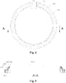
Fig. 4 is a front view of the inner drum door of the washing machine inEmbodiment 1 of the present disclosure; -
Fig. 5 is a section view of the washing machine inEmbodiment 1 of the present disclosure along a plane A-A inFig. 4 ; -
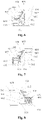
Fig. 6 is a partial enlarged view I of the washing machine inEmbodiment 1 of the present disclosure; -
Fig. 7 is a partial enlarged view II of the washing machine inEmbodiment 1 of the present disclosure; -
Fig. 8 is a partial enlarged view III of the washing machine inEmbodiment 1 of the present disclosure; -
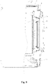
Fig. 9 is a schematic structural diagram of a washing machine inEmbodiment 2 of the present disclosure; -
Fig. 10 is a top view of an inner drum of the washing machine inEmbodiment 2 of the present disclosure; -
Fig. 11 is an exploded view of installation of an inner drum door of the washing machine inEmbodiment 2 of the present disclosure; -
Fig. 12 is a schematic structural diagram of installation the inner drum door of the washing machine inEmbodiment 2 of the present disclosure; -
Fig. 13 is an assembly diagram of a handle and a latch tongue of the washing machine inEmbodiment 2 of the present disclosure; -
Fig. 14 is a schematic diagram of a three-dimensional structure of a lock bracket of the washing machine inembodiment 2 of the present disclosure; -
Fig. 15 is a schematic diagram of a three-dimensional structure of the latch tongue of the washing machine inembodiment 2 of the present disclosure; -
Fig. 16 is a schematic structural diagram of a washing machine inEmbodiment 3 of the present disclosure; -
Fig. 17 is a partial enlarged view ofFig. 16 of the washing machine inEmbodiment 3 of the present disclosure; -
Fig. 18 is a schematic structural diagram of an electromagnetic heating device of the washing machine inEmbodiment 3 of the present disclosure; -
Fig. 19 is a schematic structural diagram of a washing machine inEmbodiment 4 of the present disclosure; -
Fig. 20 is a section view I of the washing machine inEmbodiment 4 of the present disclosure along a plane C-C inFig. 19 ; -
Fig. 21 is a section view II of the washing machine inEmbodiment 4 of the present disclosure along a plane C-C inFig. 19 ; -
Fig. 22 is a section view of an assembly diagram of an outer drum, an inner drum and an inner drum door of a washing machine inEmbodiment 5 of the present disclosure; -
Fig. 23 is a partial enlarged view ofFig. 22 of the washing machine inEmbodiment 5 of the present disclosure (an inner drum door is locked in place); and -
Fig. 24 is a partial enlarged view ofFig. 22 of the washing machine inEmbodiment 5 of the present disclosure (the inner drum door is not locked in place/not locked). - A washing machine of the present disclosure is described in detail below with reference to the accompanying drawings.
- As shown in
Fig. 1-Fig. 24 , an embodiment provides a drum washing machine with a holeless inner drum and a front-opening structure. The structure is simple, and washing/rinsing water does not need to be filled between an inner drum and an outer drum, so that the washing water consumption of the washing machine is greatly reduced. The possibility of dirt adhesion between the inner drum and the outer drum is avoided. The user health and the user experience are greatly improved, and water resources are greatly saved. - The drum washing machine of the embodiment is provided with a
housing 1, and thehousing 1 includes anupper deck plate 2, a front panel, a rear panel and a bottom plate.Bottom legs 9 are fixedly mounted on the bottom plate and used for supporting the whole washing machine. Anouter drum 19 is arranged in thehousing 1, and aninner drum 18 is coaxially arranged in theouter drum 19. Theouter drum 19 is mainly used for collecting drained water of theinner drum 18 and drained water caused by high-speed centrifugal dewatering of theinner drum 18. Theinner drum 18 rotates, and preferably, liftingribs 10 are arranged to continuously lift clothes, make the clothes drop off and beat the clothes, so that the clothes are cleaned conveniently. Theinner drum 18 is of a holeless structure, theouter drum 19 is provided with a central mounting hole where abearing 11 is mounted and fixed. Aninner drum shaft 12 which is fixedly connected with theinner drum 18 penetrates through thebearing 11 and is connected with a drivingmotor 15. An openable/closeableinner drum door 6 is mounted on a front opening of theinner drum 18, and therefore theinner drum 18 is of a sealed cabin structure. - In order to introduce water into the holeless inner drum of the embodiment, the driving
motor 15 of the drum washing machine in the embodiment is in transmission connection with theinner drum 18 through theinner drum shaft 12 to drive theinner drum 18 to rotate, a hollow channel communicating with an interior of theinner drum 18 is formed in theinner drum shaft 12, and awater inflow pipeline 17 communicates with the hollow channel of theinner drum shaft 12. - In the embodiment, the
inner drum 18 is provided with a pressure balancing mechanism used for communicating theinner drum 18 with the external environment so as to balance the pressure in the inner drum. - When water inflows, air in a sealed cabin of the inner drum is compressed and can overflow through the pressure balancing mechanism, and thus pressure balance is guaranteed.
- When water is suddenly cut off, external air can quickly enter the sealed cabin of the inner drum and destroy suck-back, pressure balance is guaranteed, and washing water is prevented from being sucked into a tap water pipeline.
- During dewatering for example, the pressure balancing mechanism can also ensure the pressure balance of the inner drum.
- As an implementation mode of the embodiment, the pressure balancing mechanism includes a pressure equalizing hole channel arranged on the
inner drum 18, and one end, communicating with the interior of theinner drum 18, of the pressure equalizing hole channel is arranged at the position, close to a rotating central shaft, of theinner drum 18 and is always higher than the highest water level in theinner drum 18. - Specifically, the pressure equalizing hole channel is formed in the
inner drum shaft 12 to communicate the interior of theinner drum 18 with the external environment, and the highest water level in theinner drum 18 is lower than theinner drum shaft 12. Therefore, water in theinner drum 18 can be prevented from flowing out of the pressure equalizing hole channel. - In the embodiment, the pressure equalizing hole channel includes a first hole channel section and a second hole channel section, the first hole channel section is parallel to the hollow channel, one end of the first hole channel section communicates with the interior of the inner drum, one end of the second hole channel section communicates with the first hole channel section, and the other end of the second hole channel section extends to a peripheral wall of the inner drum shaft to communicate with the interior of the outer drum. Preferably, the second hole channel section is perpendicular to the first hole channel section to form an L-shaped pressure equalizing hole channel.
- According to the front-opening drum washing machine with the inner drum in the embodiment, the inner drum door is arranged on the inner drum, washing in a closed space of the inner drum is achieved, the possibilities that the clothes in the inner drum come out, the clothes flow out from the inner drum due to compression and beating or water is splashed out, and the dirt is attached between the inner drum and the outer drum are avoided, and no water exists between the drums.
- In the embodiment, the washing machine is provided with a door lock detection device for detecting whether an inner drum door lock is locked in place, which ensures that the inner drum door is locked in place, and achieves 100% of locking judgment accuracy. Due to the fact that the dewatering rotating speed of the drum can reach 1600 revolutions per minute, if the inner drum door on the inner drum is not locked well, safety accidents can happen. The safety of the washing machine, the user health and the user experience are greatly improved.
- As shown in
Fig. 1-Fig. 8 , a washing machine in the embodiment includes: - an
inner drum 18, provided with a washing cavity for independently containing washing water; - an
inner drum door 6, mounted at an opening of theinner drum 18 in an openable and closable mode; - the
inner drum door 6 including a door bodyinner shell 603, a door bodyouter shell 601 and a door body lining 604; and - the door body lining 604 being clamped and fixed between the door body
inner shell 603 and the door bodyouter shell 601. - According to the embodiment, the
inner drum 18 is sealed by mounting the openable and closeableinner drum door 6 at the opening of theinner drum 18 to form the washing cavity for containing washing water. - As an implementation mode of the embodiment, in the embodiment, the door body lining 604 includes a blocking part that is matched with the opening of the
inner drum 18 in shape, and a connectingpart 615 that is located at the periphery of the blocking part, and the connectingpart 615 is clamped and fixed between the door bodyinner shell 603 and the door bodyouter shell 601. - Further, the blocking part includes a blocking
face 613 and atransition wall 614 that extends from the periphery of the blockingface 613 in an axial direction of theinner drum 18, and the connectingpart 615 is an annular connecting wall formed by outward flanging of the periphery of thetransition wall 614. - In order to achieve fixed mounting of the door body lining 604, in the embodiment, the door body
inner shell 603 includes an annular inner shell body, an inner shell connecting part and an innershell extrusion part 611 that are arranged on the inner shell connecting part; the door bodyouter shell 601 includes an annular shell body, a shell connecting part and an outershell extrusion part 612 that are arranged on the outer shell body; the inner shell connecting part and the outer shell connecting part are fixedly connected through a connecting piece, and the connectingpart 615 of the door body lining 604 is clamped and fixed by the innershell extrusion part 611 and the outershell extrusion part 612. - Further, the
door body shell 601 comprises ashell supporting part 610 arranged on the shell body, and the supportingpart 610 extends to the blocking part in the axial direction of the inner drum to conduct extrusion supporting. - In the embodiment, the door body lining 604 is extruded and fixed through the inner
shell extrusion part 611 and the outershell extrusion part 612, and meanwhile, the door body lining 604 is supported through the supportingpart 610, so that the stability of the door body lining 604 is guaranteed. - Preferably, the supporting
part 610 extends to the blocking 613 and/or thetransition wall 614 in the axial direction of the inner drum to conduct extrusion support. - In the embodiment, the
inner drum door 6 further includes a sealingelement 605 that is mounted on the periphery of the blocking part, and is used for maintaining the sealing performance of the opening of theinner drum 18 when theinner drum door 6 is closed. - In order to achieve fixed mounting of the sealing
element 605, in the embodiment, theouter shell body 601 is provided with an annular groove, a peripheral wall of an inner side of the inner shell body and a peripheral wall of an inner side of the annular groove are spaced, the innershell extrusion part 611 is an inner shell bulge arranged on the peripheral wall of the inner side of the inner shell body, and the connectingpart 615 of the door body lining 604 extends into the annular groove of the outer shell body to be clamped and fixed between the inner shell bulge and a bottom wall of the annular groove. - In the embodiment, the door body lining 604 and the sealing
element 605 are fixedly mounted through clamping and fixing of the door bodyouter shell 601 and the door bodyinner shell 603, and once assembly of the door bodyouter shell 601 and the door bodyinner shell 603 solves the problem about the fixed mounting of the door body lining 604 and the sealingelement 605 simultaneously, so that the mounting is easy and convenient, and the efficiency is high. - Preferably, the outer
shell extrusion part 612 is an outer shell bulge that is arranged at the position, corresponding to the inner shell bulge, of the bottom wall of the annular groove, and the connectingpart 615 of the door body lining 604 extends into the annular groove of the outer shell body to be clamped and fixed between the inner shell bulge and the outer shell bulge. - In the embodiment, the supporting
part 610 is a supporting wall formed by extending from the peripheral wall of the inner side of the annular groove to the transition wall in the axial direction of the inner drum. - In the embodiment, a mounting space used for clamping and fixing one end of the sealing element is formed between the peripheral wall of the inner side of the inner shell body and the
transition wall 614 of the door body lining 604, the periphery of the blockingface 613 of the door body lining 604 extends outwards in a radial direction to form astop ring 609, the other end of the sealingelement 605 abuts against thestop ring 609, and at least one layer of sealingband 608 is arranged between two ends of the sealingelement 605. - In the embodiment, an annular mounting groove is formed in the inner shell body, a mounting
hole 602 is formed in the annular mounting groove, and the connecting piece penetrates through the mountinghole 602 to be fixedly connected with the outer shell body; and the sealingelement 605 includes adecoration part 607, thedecoration part 607 extends above the mounting groove and covers an opening of the mounting groove, and anassembly hole 606 corresponding to the mountinghole 602 is formed in the door body outer shell. - In order to further improve the overall assembly stability of the
inner drum door 6,barb structures 616 are arranged on the door bodyinner shell 603 and/or the door bodyouter shell 601 and/or the door body lining 604, and in an example, thebarb structures 616 in the figure are arranged on the door bodyinner shell 603. - As shown in
Fig. 9-Fig. 15 , a washing machine in the embodiment includes: - an
inner drum 18, provided with a washing cavity for independently containing washing water; - an
inner drum door 6, mounted at an opening of theinner drum 18 in an openable and closable mode; and - a rotating shaft structure through which the
inner drum door 6 is rotatably mounted on an opening of theinner drum 18. - In the embodiment, the
inner drum door 6 is rotatably mounted on the opening of theinner drum 18 through the rotating shaft structure to close and open the inner drum. - Specifically, in the embodiment, the rotating shaft structure includes a
rotating shaft seat 24, a rotatingshaft 23 and a connectingarm 49, wherein therotating shaft seat 24 is fixedly mounted on the opening wall of theinner drum 18, the rotatingshaft 23 is mounted on therotating shaft seat 24, the connectingarm 49 is rotatably mounted on therotating shaft 23, and the connectingarm 49 is fixedly connected with theinner drum door 6. - Further, the
rotating shaft seat 24 includes a firstrotating shaft seat 42 and a secondrotating shaft seat 43 which are respectively fixed on the opening wall of theinner drum 18, and therotating shaft 23 is fixedly mounted between the firstrotating shaft seat 42 and the secondrotating shaft seat 43. - Preferably, the rotating
shaft 23 is a cylindrical rotating shaft, special-shaped holes 45 are respectively formed in the firstrotating shaft seat 42 and the secondrotating shaft seat 43, and two ends of the cylindrical rotating shaft are respectively and fixedly mounted in the special-shaped holes 45 of the firstrotating shaft seat 42 and the secondrotating shaft seat 43. - The rotating
shaft 23 includes acylindrical shaft body 47 and special-shapedrotating shaft parts 46 that are located at two ends of thecylindrical shaft body 47 and matched with the special-shaped holes 45 respectively. - Further, in the embodiment, the rotating shaft structure further includes a rotating shaft
seat lining plate 41 and a rotating shaft seat connecting piece, wherein the rotating shaftseat lining plate 41 and therotating shaft seat 24 are located on two sides of the opening wall of theinner drum 18 respectively; rotating shaft seat liningplate fixing holes 40 are formed in the rotating shaftseat lining plate 41, rotatingshaft fixing holes 38 are formed in the opening wall of theinner drum 18, and rotating shaft seat fixing holes 39 are formed in therotating shaft seat 24; and the rotating shaft seat connecting piece penetrates through the rotating shaft seat liningplate fixing holes 40, the rotatingshaft fixing holes 38 and the rotating shaftseat fixing hole 39 to fixedly connect the rotating shaft seat liningplate fixing holes 40, the rotatingshaft fixing holes 38 and the rotating shaft seat fixing holes 39. In the embodiment, the rotating shaftseat lining plate 41 plays the role of enhancing the strength of the position of the rotating shaft seat of the inner drum to avoid deformation. - Preferably, sealing elements are arranged between the rotating shaft seat connecting piece and the rotating shaft seat lining
plate fixing holes 40, and/or between the rotating shaft seat connecting piece and the rotatingshaft fixing holes 38, so as to prevent washing water in theinner drum 18 from leakage from the connecting position, and keep the interior of theinner drum 18 closed. - In the embodiment, the connecting
arm 49 includes ashaft hole part 48 and a connectingpart 50, wherein theshaft hole part 48 is provided with a shaft hole, thecylindrical shaft body 47 penetrates through theshaft hole 48 and can freely rotate relative to theshaft hole 48, and the connectingpart 50 is fixedly connected with theinner drum door 6. - Preferably, the
inner drum door 6 is provided with an inner drum door mountingavoidance area 608 corresponding to the connectingarm 49. - Further preferably, the inner drum door mounting
avoidance area 608 is arranged on the door bodyinner shell 603. - It can be known from the structural characteristics of the drum washing machine with the holeless inner drum that in the washing and rinsing process, the key of forming the inner cavity of the inner drum capable of independently containing washing water is to maintain the sealing performance of the inner drum door. Furthermore, in the process of the high-speed rotation of the inner drum for dewatering, if the inner drum door is not locked or is not locked in place, serious safety accidents may be caused. Therefore, in the embodiment, the washing machine further includes an inner drum door lock, wherein the inner drum door lock includes a
lock bracket assembly 22 and alatch tongue assembly 21, thelock bracket assembly 22 is fixed on the opening wall of theinner drum 18, thelatch tongue assembly 21 is fixed on theinner drum door 6, and thelatch tongue assembly 21 and thelock bracket assembly 22 are matched in a locking mode to lock the inner drum door. - Furthermore, the
lock bracket assembly 22 includes abracket body 33, alock hook 32, a lockbracket lining plate 36 and a lock bracket connecting piece, wherein thelock hook 32 is arranged on thebracket body 33, and the lockbracket lining plate 36 and thebracket body 33 are located on the two sides of the opening wall of theinner drum 18 respectively. A lock bracket liningplate fixing hole 35 is formed in the lockbracket lining plate 36, a lock bracket fixing hole is formed in the opening wall of theinner drum 18, and a lockbracket fixing hole 34 is formed in thebracket body 33; the lock bracket connecting piece penetrates through the lock bracket liningplate fixing hole 35, the lock bracket fixing hole and the lockbracket fixing hole 34 to fixedly connect the lock bracket liningplate fixing hole 35, the lock bracket fixing hole and the lockbracket fixing hole 34. - Preferably, sealing elements are arranged between the lock bracket connecting piece and the lock bracket lining
plate fixing hole 35, and/or between the lock bracket connecting piece and the lock bracket fixing hole respectively. - Further, in the embodiment, the
latch tongue assembly 21 includes alatch tongue 30, a latchtongue rotating shaft 29 and ahandle 25, wherein the latchtongue rotating shaft 29 is fixedly mounted on theinner drum door 18, thelatch tongue 30 and thehandle 25 are rotatably mounted on the latchtongue rotating shaft 29, and thehandle 25 and thelatch tongue 30 are matched to drive thelatch tongue 30 to rotate so as to lock/unlock the inner drum door. - Further, in the embodiment, the
latch tongue assembly 21 further includes atorsion spring 28, the latchtongue rotating shaft 29 is sleeved with thetorsion spring 28, one end of thetorsion spring 28 is fixedly connected with theinner drum door 6, and the other end of thetorsion spring 28 is fixedly connected with thelatch tongue 30. - Preferably, the
inner drum door 6 is provided with a torsion spring fixing hole or a torsion spring fixing groove used for assembling thetorsion spring 28, and thelatch tongue 30 is provided with a torsion spring fixing hole or a torsion spring fixing groove used for assembling thetorsion spring 28. - In the embodiment, the
torsion spring 28 includes a torsion spring inner drumdoor fixing part 27 connected with theinner drum door 6, and a torsion spring locktongue fixing part 31 connected with thelock tongue 30. - As an implementation mode of the embodiment, the
inner drum door 6 is provided with a mountingarea 607 used for mounting the latch tongue assembly. - Preferably, the
inner drum door 6 includes a door bodyinner shell 603, a door bodyouter shell 601 and a door body lining 604, wherein the door body lining 604 is clamped and fixed between the door bodyinner shell 603 and the door bodyouter shell 601, and the mountingarea 607 is arranged on the door bodyouter shell 601. - Preferably, the
installation area 607 is a mounting groove formed in the door bodyouter shell 601. - As shown in
Fig. 16-Fig. 18 , in the embodiment, a washing machine includes: - an
inner drum 18, provided with a washing cavity for independently containing washing water; - an
outer drum 19, arranged outside theinner drum 18 in a sleeving manner; and - an electromagnetic heating device, arranged on a side wall of the
outer drum 19 and corresponding to a side wall, to be heated, of theinner drum 18. - The embodiment provides the washing machine which is provided with the electromagnetic heating device that heats the side wall of the
inner drum 18, the side wall of theinner drum 18 is heated by the electromagnetic heating device, and then heat is transferred to washing water in theinner drum 18, thereby heating the washing water. - Electromagnetic heating is also known as electromagnetic induction heating, namely an electromagnetic heating (EH for short) technology. The principle of electromagnetic heating is that an alternating magnetic field is generated through an electronic circuit board component, when an irony container is placed on the electromagnetic heating device, alternating magnetic lines are cut by the surface of the container, and alternating current (namely eddy current) is generated on a metal part at the bottom of the container, the eddy current enables carriers at the bottom of the container to move irregularly at a high speed, and the carriers and atoms are subjected to collision and friction mutually to generate heat energy. Therefore, the effect of heating articles is achieved. As the irony container emits heat, the heat conversion rate is particularly high and can reach 95% at most, and a direct heating mode is adopted. Therefore, in the embodiment, a pulsator washing machine utilizes the electromagnetic heating device to heat washing water, and the heating efficiency is higher.
- In addition, due to the fact that electromagnetic heating is a non-contact heating mode, the mounting requirement of the electromagnetic heating device is lower than that of a conventional electric heating wire heating mode which needs to consider the sealing performance, and therefore the washing machine adopting the electromagnetic heating device has a more simplified installation. In addition, in order to mount an electric heating wire, a mounting position and a mounting structure of the electric heating wire need to be specially designed in the outer drum, the electromagnetic heating device in the embodiment can be directly mounted on an inner wall or an outer wall of the outer drum and even mounted in a tank body, the structure of the outer drum is simplified, the volume of the inner drum can be enlarged to a certain degree, and capacity expansion is achieved.
- Further, according to a resistance wire heating mode adopted by an existing washing machine, a resistance wire is immersed in water for direct heating, due to the fact that the water environment is complex, scales deposit on the resistance wire along with the increase of time, and the resistance wire is not easy to clean due to the mounting position, so that the heating efficiency is gradually reduced, and even damage is caused. In the embodiment, the electromagnetic heating device is adopted to achieve non-contact heating, so that the above problem can be solved, the service life is greatly prolonged, and long-term high-efficiency heating can be kept.
- In conclusion, in the embodiment, the washing machine adopts the electromagnetic heating device to achieve the heating function, the heating efficiency is improved, the mounting of the heating device is simplified, the structure of the outer drum is simplified, and the service life of the heating device is prolonged.
- In the embodiment, the inner drum is made of irony materials and can cut alternating magnetic lines generated by the electromagnetic heating device to generate alternating current (namely eddy current 55), the
eddy current 55 enables carriers on the side wall of the inner drum to move irregularly at a high speed, and the carriers are subjected to collision and friction mutually to generate heat energy. - Further, in the embodiment, the electromagnetic heating device is arranged on the inner side wall of the outer drum.
- Preferably, the electromagnetic heating device is arranged at the lowest position of the inner side wall of the
outer drum 19, which has the advantages that water is concentrated at the bottom of theinner drum 18, and washing water in theinner drum 18 is gathered at the bottom no matter how theinner drum 18 rotates, so that heat is immediately transferred to water when theinner drum 18 is heated, thereby achieving the heating safety and high heating efficiency of theinner drum 18. - In addition, the electromagnetic heating device is arranged at the bottom, there is a certain amount of residual water during each drainage, and an electromagnetic coil of the electromagnetic heating device dissipates heat.
- As an implementation mode of the embodiment, in the embodiment, the electromagnetic heating device includes an
electromagnetic coil 59 and a mountingframe 58, wherein theelectromagnetic coil 59 is fixed on the mountingframe 58, and the mountingframe 58 is fixed on the inner side wall of theouter drum 19. - Preferably, the mounting
frame 58 includes a mounting shell made of a non-metal material, and theelectromagnetic coil 59 is packaged in the mounting shell. - Further, the mounting
frame 58 includes a fixing part, an assembling part matched with the fixing part is arranged on the inner side wall of theouter drum 19, and the fixing part is fixedly connected with the assembling part through a connectingpiece 56. - Specifically, a mounting groove is formed in the inner side wall of the
outer drum 19, the mountingframe 58 is installed in the mounting groove, and the mountingframe 58 is provided with a transition curved surface which is in transition connection with the inner side wall of theouter drum 19. Therefore, the accumulation of dirt at the mounting groove is avoided. - As another implementation mode of the embodiment, the electromagnetic heating device includes an electromagnetic coil, a mounting groove is formed in the inner side wall of the outer drum, the electromagnetic coil is arranged in the mounting groove, and a sealing plate made of non-metal materials is mounted on an opening of the mounting groove in a sealing mode.
- A coil distance refers to a distance H between a surface of the wound electromagnetic coil and a surface of the inner drum, and in order to achieve high heating efficiency, the distance cannot be too long or too short. Specifically, the distance between the upper surface of the electromagnetic coil and the surface of the outer side wall of the inner drum is H, and the H satisfies 0.4 cm≤H≤10 cm;
- preferably, the H is 1 cm~3 cm; and
- further preferably, the H is 2±0.5 cm.
- Further, in the embodiment, the electromagnetic heating device includes a heat dissipation piece used for dissipating heat of the electromagnetic coil, so that the better heat dissipation of the wound coil is achieved.
- Preferably, the heat dissipation piece is arranged on the mounting frame or the sealing plate.
- The embodiment of the present disclosure also provides a control method of a washing machine. In the washing and/or rinsing process of the washing machine, an electromagnetic heating device is controlled to be started, and meanwhile, an inner drum is controlled to rotate to heat washing water.
- Further, in the embodiment, the washing machine includes a temperature detection device used for detecting the temperature of the washing water, and when the temperature detection device detects that the temperature of washing water reaches a set temperature, the electromagnetic heating device is controlled to stop working;
or, the washing machine detects a water inflow amount Q and an inflowing water initial temperature t0. A target heating temperature t set by a user is received by the washing machine, heating time T of the washing machine is calculated, and the electromagnetic heating device is controlled to stop working when the working time of the electromagnetic heating device reaches the heating time T. - As shown in
Figs. 19-21 , in the embodiment, a washing machine includes: - an
inner drum 18, provided with a washing cavity for independently containing washing water; - an
inner drum door 6, mounted at an opening of theinner drum 18 in an openable and closable mode; - a
housing 1, provided with a feeding opening corresponding to the opening of theinner drum 18; - a
housing door 5, mounted on the feeding opening of thehousing 1 in an openable and closable mode; and - a
door opening mechanism 62, being triggered to act to realize linkage opening and closing of theinner drum door 6 and thehousing door 5. - In the embodiment, the linkage opening and closing of the
inner drum door 6 and thehousing door 5 is achieved through thedoor opening mechanism 62, the trouble that a user opens and closes theinner drum door 6 and thehousing door 5 separately is avoided, the operation of the user is facilitated, and the use experience of the user is improved. - Specifically, the
door opening mechanism 62 includes a trigger piece, and the trigger piece has at least two action/position states that correspondingly control the sequential linkage opening and closing of the housing door and the inner drum door. - As an implementation mode of the embodiment, the trigger piece includes a deformation part. Deformation displacement is generated by pressing the deformation part to control the sequential linkage unlocking of the housing door and the inner drum door, and the deformation displacement corresponding to unlocking of the housing door is smaller than the deformation displacement corresponding to unlocking of the inner drum door.
- As an implementation mode of the embodiment, the trigger piece includes a moving part. Displacement is generated by controlling the moving part to control the sequential linkage unlocking of the housing door and the inner drum door, and the displacement corresponding to unlocking of the housing door is smaller than the displacement corresponding to unlocking of the inner drum door.
- Further, the
housing door 5 is provided with a through channel, the trigger piece is arranged in the through channel, and the trigger piece is provided with a deformation part or a moving part. The housing door is provided with a housing door triggering piece for triggering unlocking of the housing door, and the inner drum door is provided with an inner drum door triggering piece for triggering unlocking of the inner drum door; and by pressing the deformation part or the moving part of the trigger piece, the position state is switched in the through channel to trigger the housing door triggering piece and the inner drum door triggering piece to act sequentially. - In the embodiment, an inner drum door lock is arranged on the
inner drum door 6, and an inner drumdoor triggering piece 65 triggers the inner drum door lock to be unlocked; ahousing door lock 63 is arranged on thehousing door 5, and the housing door triggering piece triggers the housing door lock to be unlocked. - Specifically, the inner drum door lock includes an inner drum door lock bracket and an inner drum door lock tongue, the inner drum door triggering piece is an inner drum door handle in linkage with the inner drum door lock tongue, and the trigger piece triggers the inner drum door handle to act to drive the inner drum door lock tongue to be in linkage for unlocking.
- Specifically, the housing door lock includes a housing door lock bracket and a housing door lock tongue, the housing door triggering piece is in linkage with the housing door lock tongue, and the trigger piece triggers the housing door triggering piece to act to drive the housing door lock tongue to be in linkage for unlocking;
or, the housing door lock is an electromagnetic lock, the housing door triggering piece is a trigger switch, and the trigger piece triggers the trigger switch to act to generate a control signal for controlling the electromagnetic lock to be unlocked/locked. - Further, in the embodiment, the washing machine further includes an inner drum locking device used for locking the inner drum to be located at a determined position, and the inner drum door triggering piece is arranged corresponding to the position of the through channel where the inner drum is located in a state that the inner drum is locked by the inner drum locking device.
- As an implementation mode of the embodiment, the door opening mechanism includes a linkage assembly, wherein the linkage assembly is in linkage connection with the housing door and the inner drum door, and the trigger piece triggers the linkage assembly to drive the housing door and the inner drum door to be subjected to sequential linkage unlocking/locking.
- As shown in
Fig. 22 to Fig. 24 , in the embodiment, a washing machine includes: - an
inner drum 18, provided with a washing cavity for independently containing washing water; - an
inner drum door 6, mounted at an opening of theinner drum 18 in an openable and closable mode; - an inner drum door lock, used for locking the
inner drum door 6 to keep a closed state; and - a door
lock detection device 66, used for detecting whether the inner drum door lock is locked or not. - The embodiment discloses a drum washing machine with a holeless inner drum and a front-opening structure, the
inner drum 18 is a holeless structure. It can be known from the structural characteristics of the drum washing machine with the holeless inner drum that in the washing and rinsing process, the key of forming the inner cavity of the inner drum capable of independently containing washing water is to maintain the sealing performance of the inner drum door. Furthermore, in the process of the high-speed rotation of the inner drum for dewatering, if the inner drum door is not locked or is not locked in place, serious safety accidents may be caused. According to the washing machine in the embodiment, the door lock detection device is adopted to detect the inner drum door lock, and whether the inner drum door lock is locked or not is directly related to whether the inner drum door is locked in place, so that the doorlock detection device 66 can more directly detect the state of the inner drum door, and the situation that the inner drum door is not locked in place is fundamentally eradicated. - Further, in the embodiment, the inner drum door lock includes a
latch tongue 30 mounted on theinner drum door 6 and alock bracket 24 mounted on the opening of theinner drum 18. The washing machine includes anouter drum 19 coaxially arranged outside theinner drum 18, and the doorlock detection device 66 is arranged on theouter drum 19 and used for detecting whether thelatch tongue 30 is locked in alock bracket 24 or not. - In the embodiment, according to a specific structure of the inner drum door lock, the door lock detection device directly detects whether the
latch tongue 30 of the inner drum door lock is locked in thelock bracket 24 or not, so that whether theinner drum door 6 is locked or not can be accurately judged, the in-place locking accuracy of the inner drum door is greatly improved, and potential safety hazards caused by not-in-place locking are avoided. - Further, due to the fact that a displacement difference of the
latch tongue 30 of the inner drum door in the locking state and the unlocking state is small, the higher requirement is required for the detection precision of the door lock detection device if the action of the latch tongue needs to be accurately detected, but the cost of the door lock detection device is certainly increased. According to the washing machine in the embodiment, the detection accuracy of the door lock detection device is improved. In order to reduce the cost of the door lock detection device as much as possible and ensure the detection precision, the washing machine further includes a door lock triggering device, and the door lock triggering device is in linkage with thelatch tongue 30 to enter a detection range of the doorlock detection device 66 in the locking process of the inner drum door lock. - In the embodiment, the door lock triggering device is arranged and is in linkage with the latch tongue when the inner drum door lock is locked, the door lock triggering device can amplify the displacement of the latch tongue when the inner drum door lock is locked, the displacement can be more easily detected by the door
lock detection device 66, and thus, the detection accuracy is ensured. - As an implementation mode of the embodiment, in the embodiment, the door lock triggering device includes a
movable piece 68 that can move in a reciprocating manner, and anelastic piece 70 that is arranged between themovable piece 68 and thelock bracket 24; aninduction piece 67 which can be detected by the doorlock detection device 66 is arranged on themovable piece 68; themovable piece 68 is in linkage with thelatch tongue 30 in the locking process of the inner drum door lock, and the doorlock detection device 66 generates a detection signal after detecting theinduction part 67 entering the detection range. - In the embodiment, the
movable piece 68 of the door lock triggering device is in linkage along with the latch tongue when the inner drum door lock is locked, the small displacement of the latch tongue can be amplified, or the displacement position of the latch tongue is extended to be within the detection range of the doorlock detection device 66, and therefore, the locking state of the inner drum door lock can be accurately detected. - According to the door lock triggering device, in the locking process of the inner drum door lock, the movable piece and the latch tongue are in linkage to compress the
elastic piece 70, theelastic piece 70 elastically deforms, when the inner drum door lock is unlocked, the movable piece is not resisted by thelatch tongue 30 anymore, and theelastic piece 70 recovers deformation to push themovable piece 68 to reset so as to detect the next locking process. - Further, the
lock bracket 24 includes a bracket body and a locking piece arranged in the bracket body, one end of theelastic piece 70 is fixed in the bracket body, the other end of theelastic piece 70 is connected with themovable piece 68 and extends to the locking piece, and thelatch tongue 30 is locked in the locking piece and abuts against themovable piece 68 to push themovable piece 68 to move into the detection range of the doorlock detection device 66. - In the embodiment, an opening is formed in the locking piece, and at least part of the
movable piece 68 extends into the locking piece from the opening under the action of theelastic piece 70. - The door lock triggering device includes a limiting
piece 69 that is arranged on the movable piece and used for preventing themovable piece 68 from being disengaged from the interior of the lock bracket. - Preferably, the limiting
piece 69 is a limiting bulge arranged on themovable piece 68, one end of themovable piece 68 extends into the locking piece through the opening, and the other end of themovable piece 68 is limited outside the opening by the limiting bulge. - As an implementation mode of the embodiment, the
induction piece 67 is a permanent magnet, and the doorlock detection device 66 includes a magnetic induction element capable of inducing the permanent magnet; and preferably, the permanent magnet is a magnet, and the magnetic induction element is a reed switch. - In the embodiment, an inducing distance range of the reed switch is L.
- As shown in
Fig. 23 , in the embodiment, theinner drum door 6 is locked in place, thelatch tongue 30 is in place, thelatch tongue 30 presses themovable piece 68 and the magnet to a direction of the outer drum wall, the distance between the magnet and the reed switch is H which is smaller than or equal to L or is smaller than L. The reed switch is pulled in to be conductive, and thus it is judged that the door body is locked in place. - As shown in
Fig. 24 , when theinner drum door 6 is not locked in place or opened and thelatch tongue 30 is not in place, theelastic piece 70 presses themovable piece 68 towards a direction away from the outer drum wall, the distance between the magnet and the reed switch is H + h, which is larger than L. The reed switch is not pulled in to be separated, and thus it is judged that the door body is not locked in place. - The above description is only preferred embodiments of the present disclosure, and is not intended to limit the present disclosure in any way. Although the present disclosure has been disclosed in the preferred embodiments, it is not intended to limit the present disclosure. Any technician familiar with this patent can make some changes or modifications to form equivalent embodiments with equivalent changes by using the above-mentioned suggestive technical contents without departing from the scope of the technical solution of the present disclosure. However, any simple amendments, equivalent changes and modifications made to the above embodiments according to the technical essence of the present disclosure without departing from the contents of the technical solution of the present disclosure are still within the scope of the solution of the present disclosure.
Claims (10)
- A washing machine comprising:an inner drum, provided with a washing cavity for independently containing washing water;an inner drum door, mounted at an opening of the inner drum in an openable and closable mode; characterized in that,the inner drum door comprises a door body inner shell, a door body outer shell and a door body lining; andthe door body lining is clamped and fixed between the door body inner shell and the door body outer shell.
- The washing machine according to claim 1, characterized in that the door body lining comprises a blocking part that is matched with the opening of the inner drum in shape and a connecting part that is located at a periphery of the blocking part, and the connecting part is clamped and fixed between the door body inner shell and the door body outer shell.
- The washing machine according to claim 2, characterized in that the blocking part comprises a blocking face and a transition wall that extends from a periphery of the blocking face in an axial direction of the inner drum, and the connecting part is an annular connecting wall formed by outward flanging of a periphery of the transition wall.
- The washing machine according to claim 2, characterized in that the door body inner shell comprises an annular inner shell body, an inner shell connecting part and an inner shell extrusion part that are arranged on the inner shell body; the door body outer shell comprises an annular outer shell body, an outer shell connecting part and an outer shell extrusion part that are arranged on the outer shell body; and
the inner shell connecting part and the outer shell connecting part are fixedly connected through a connecting piece, and the connecting part of the door body lining is clamped and fixed by the inner shell extrusion part and the outer shell extrusion part. - The washing machine according to claim 4, characterized in that the door body outer shell comprises an outer shell supporting part arranged on the outer shell body, and the supporting part extends to the blocking part in the axial direction of the inner drum to conduct extrusion support; and
preferably, the supporting part extends to the blocking face and/or to the transition wall in the axial direction of the inner drum to conduct extrusion support. - The washing machine according to claim 2, characterized in that the inner drum door comprises a sealing element mounted on the periphery of the blocking part.
- The washing machine according to any one of claims 4-6, characterized in that the outer shell body is provided with an annular groove, a peripheral wall of an inner side of the inner shell body and a peripheral wall of an inner side of the annular groove are spaced, the inner shell extrusion part is an inner shell bulge arranged on the peripheral wall of the inner side of the inner shell body, and the connecting part of the door body lining extends into the annular groove of the outer shell body to be clamped and fixed between the inner shell bulge and a bottom wall of the annular groove; and
preferably, an outer shell bulge is arranged at a position, corresponding to the inner shell bulge, of the bottom wall of the annular groove, and the connecting part of the door body lining extends into the annular groove of the outer shell body to be clamped and fixed between the inner shell bulge and the outer shell bulge. - The washing machine according to claim 7, characterized in that the supporting part is a supporting wall formed by extending from the peripheral wall of the inner side of the annular groove to the transition wall in the axial direction of the inner drum.
- The washing machine according to claim 7, characterized in that a mounting space used for clamping and fixing one end of the sealing element is formed between the peripheral wall of the inner side of the inner shell body and the transition wall of the door body lining, and the periphery of the blocking face of the door body lining extends outwards in a radial direction to form a stop ring; and the other end of the sealing element abuts against the stop ring, and at least one layer of sealing band is arranged between two ends of the sealing element.
- The washing machine according to claim 9, characterized in that an annular mounting groove is formed in the inner shell body, a mounting hole is formed in the annular mounting groove, and the connecting piece penetrates through the mounting hole to be fixedly connected with the outer shell body; and the sealing element comprises a decoration part, and the decoration part extends above the mounting groove and covers an opening of the mounting groove.
Applications Claiming Priority (2)
| Application Number | Priority Date | Filing Date | Title |
|---|---|---|---|
| CN201910767605.6A CN112411130B (en) | 2019-08-20 | 2019-08-20 | a washing machine |
| PCT/CN2020/109440 WO2021032037A1 (en) | 2019-08-20 | 2020-08-17 | Washing machine |
Publications (4)
| Publication Number | Publication Date |
|---|---|
| EP4019688A1 true EP4019688A1 (en) | 2022-06-29 |
| EP4019688A4 EP4019688A4 (en) | 2022-10-26 |
| EP4019688B1 EP4019688B1 (en) | 2024-06-19 |
| EP4019688C0 EP4019688C0 (en) | 2024-06-19 |
Family
ID=74659905
Family Applications (1)
| Application Number | Title | Priority Date | Filing Date |
|---|---|---|---|
| EP20853722.5A Active EP4019688B1 (en) | 2019-08-20 | 2020-08-17 | Washing machine |
Country Status (4)
| Country | Link |
|---|---|
| EP (1) | EP4019688B1 (en) |
| JP (1) | JP7457792B2 (en) |
| CN (1) | CN112411130B (en) |
| WO (1) | WO2021032037A1 (en) |
Families Citing this family (4)
| Publication number | Priority date | Publication date | Assignee | Title |
|---|---|---|---|---|
| CN115216939B (en) * | 2021-04-15 | 2025-08-19 | 青岛海尔洗衣机有限公司 | Clothes treatment equipment |
| CN116949761A (en) * | 2022-04-12 | 2023-10-27 | 青岛海尔洗涤电器有限公司 | Inner barrel door structure and drum type washing machine |
| CN117684358B (en) * | 2023-11-16 | 2025-10-28 | 珠海格力电器股份有限公司 | Clothes processing device |
| WO2025241939A1 (en) * | 2024-05-23 | 2025-11-27 | 青岛海尔洗衣机有限公司 | Protruding structure, door seal, door, drum assembly, and laundry treatment device |
Family Cites Families (11)
| Publication number | Priority date | Publication date | Assignee | Title |
|---|---|---|---|---|
| KR100617224B1 (en) * | 1999-11-30 | 2006-08-31 | 엘지전자 주식회사 | Drum Washing Machine |
| KR100595180B1 (en) * | 2002-07-31 | 2006-07-03 | 엘지전자 주식회사 | Door of laundry / drum washing machine |
| JP3862721B2 (en) * | 2004-11-18 | 2006-12-27 | シャープ株式会社 | Dryer |
| DE102005043769B4 (en) * | 2005-09-13 | 2009-01-29 | Miele & Cie. Kg | Porthole door for a front-loading laundry machine such as a washing machine, washer-dryer or tumble dryer |
| JP2007130359A (en) * | 2005-11-14 | 2007-05-31 | Sanyo Electric Co Ltd | Drum type washing machine |
| CN106436135B (en) * | 2016-08-30 | 2019-03-22 | 无锡小天鹅股份有限公司 | Roller washing machine |
| CN206273863U (en) * | 2016-12-07 | 2017-06-23 | 山东小鸭集团洗涤机械有限公司 | A kind of health isolated washing machine of sustainable inner cylinder door |
| CN206521635U (en) * | 2016-12-28 | 2017-09-26 | 青岛海尔洗衣机有限公司 | A kind of clothes dryer door body structure and dryer |
| CN108866922B (en) * | 2017-05-09 | 2021-04-27 | 青岛海尔滚筒洗衣机有限公司 | A drum washing machine |
| CN208279896U (en) * | 2018-04-12 | 2018-12-25 | 青岛海尔洗涤电器有限公司 | A kind of door body and clothes treatment device of clothes treatment device |
| CN208869842U (en) * | 2018-08-13 | 2019-05-17 | 苏州中隆机电配件有限公司 | A kind of gasket structure |
-
2019
- 2019-08-20 CN CN201910767605.6A patent/CN112411130B/en active Active
-
2020
- 2020-08-17 JP JP2022510143A patent/JP7457792B2/en active Active
- 2020-08-17 EP EP20853722.5A patent/EP4019688B1/en active Active
- 2020-08-17 WO PCT/CN2020/109440 patent/WO2021032037A1/en not_active Ceased
Also Published As
| Publication number | Publication date |
|---|---|
| WO2021032037A1 (en) | 2021-02-25 |
| JP2022553603A (en) | 2022-12-26 |
| JP7457792B2 (en) | 2024-03-28 |
| EP4019688B1 (en) | 2024-06-19 |
| EP4019688A4 (en) | 2022-10-26 |
| CN112411130A (en) | 2021-02-26 |
| CN112411130B (en) | 2023-06-13 |
| EP4019688C0 (en) | 2024-06-19 |
Similar Documents
| Publication | Publication Date | Title |
|---|---|---|
| EP4019688B1 (en) | Washing machine | |
| CN112481945B (en) | Washing machine and control method thereof | |
| JP7358693B2 (en) | drum type washing machine | |
| US9303348B2 (en) | Washing machine having buoyancy clutch | |
| WO2021023242A1 (en) | Washing machine and control method therefor | |
| US20130276483A1 (en) | Washing machine | |
| EP3623512B1 (en) | Drum washing machine | |
| CN207295247U (en) | A kind of washing machine | |
| CN112411112B (en) | A washing machine | |
| CN111394935A (en) | Control method of drum washing machine and drum washing machine | |
| CN112411131B (en) | a washing machine | |
| CN111139626B (en) | Drainage device of washing machine, washing machine and control method of washing machine | |
| CN111663296A (en) | A washing machine and its control method | |
| JP2022540294A (en) | Drum washing machine and its control method | |
| WO2021023243A1 (en) | Washing machine and control method therefor | |
| CN111663297A (en) | A washing machine and its control method | |
| CN101424024A (en) | Detection method and system for detecting dewatering barrel operation status in washing machine | |
| CN111945361A (en) | Drum washing machine | |
| CN113389012A (en) | Washing machine | |
| CN111394927A (en) | Drum washing machine and control method thereof | |
| CN111379116A (en) | Drum washing machine and control method thereof | |
| CN210946137U (en) | Pulsator washing machine | |
| JP7458572B2 (en) | Drum washing machine and its control method | |
| EP3730687A1 (en) | Apparatus for treating clothes | |
| CN200985438Y (en) | Drum washing machine |
Legal Events
| Date | Code | Title | Description |
|---|---|---|---|
| STAA | Information on the status of an ep patent application or granted ep patent |
Free format text: STATUS: THE INTERNATIONAL PUBLICATION HAS BEEN MADE |
|
| PUAI | Public reference made under article 153(3) epc to a published international application that has entered the european phase |
Free format text: ORIGINAL CODE: 0009012 |
|
| STAA | Information on the status of an ep patent application or granted ep patent |
Free format text: STATUS: REQUEST FOR EXAMINATION WAS MADE |
|
| 17P | Request for examination filed |
Effective date: 20220318 |
|
| AK | Designated contracting states |
Kind code of ref document: A1 Designated state(s): AL AT BE BG CH CY CZ DE DK EE ES FI FR GB GR HR HU IE IS IT LI LT LU LV MC MK MT NL NO PL PT RO RS SE SI SK SM TR |
|
| A4 | Supplementary search report drawn up and despatched |
Effective date: 20220922 |
|
| RIC1 | Information provided on ipc code assigned before grant |
Ipc: D06F 39/14 20060101ALN20220919BHEP Ipc: F16J 15/10 20060101ALI20220919BHEP Ipc: D06F 37/28 20060101ALI20220919BHEP Ipc: D06F 37/10 20060101AFI20220919BHEP |
|
| DAV | Request for validation of the european patent (deleted) | ||
| DAX | Request for extension of the european patent (deleted) | ||
| GRAP | Despatch of communication of intention to grant a patent |
Free format text: ORIGINAL CODE: EPIDOSNIGR1 |
|
| STAA | Information on the status of an ep patent application or granted ep patent |
Free format text: STATUS: GRANT OF PATENT IS INTENDED |
|
| RIC1 | Information provided on ipc code assigned before grant |
Ipc: D06F 39/14 20060101ALN20240110BHEP Ipc: F16J 15/10 20060101ALI20240110BHEP Ipc: D06F 37/28 20060101ALI20240110BHEP Ipc: D06F 37/10 20060101AFI20240110BHEP |
|
| INTG | Intention to grant announced |
Effective date: 20240201 |
|
| GRAS | Grant fee paid |
Free format text: ORIGINAL CODE: EPIDOSNIGR3 |
|
| RAP1 | Party data changed (applicant data changed or rights of an application transferred) |
Owner name: HAIER SMART HOME CO., LTD. Owner name: QINGDAO HAIER LAUNDRY ELECTRIC APPLIANCES CO., LTD. |
|
| GRAA | (expected) grant |
Free format text: ORIGINAL CODE: 0009210 |
|
| STAA | Information on the status of an ep patent application or granted ep patent |
Free format text: STATUS: THE PATENT HAS BEEN GRANTED |
|
| AK | Designated contracting states |
Kind code of ref document: B1 Designated state(s): AL AT BE BG CH CY CZ DE DK EE ES FI FR GB GR HR HU IE IS IT LI LT LU LV MC MK MT NL NO PL PT RO RS SE SI SK SM TR |
|
| REG | Reference to a national code |
Ref country code: GB Ref legal event code: FG4D |
|
| REG | Reference to a national code |
Ref country code: CH Ref legal event code: EP |
|
| REG | Reference to a national code |
Ref country code: DE Ref legal event code: R096 Ref document number: 602020032756 Country of ref document: DE |
|
| U01 | Request for unitary effect filed |
Effective date: 20240718 |
|
| U07 | Unitary effect registered |
Designated state(s): AT BE BG DE DK EE FI FR IT LT LU LV MT NL PT SE SI Effective date: 20240729 |
|
| PG25 | Lapsed in a contracting state [announced via postgrant information from national office to epo] |
Ref country code: HR Free format text: LAPSE BECAUSE OF FAILURE TO SUBMIT A TRANSLATION OF THE DESCRIPTION OR TO PAY THE FEE WITHIN THE PRESCRIBED TIME-LIMIT Effective date: 20240619 |
|
| PG25 | Lapsed in a contracting state [announced via postgrant information from national office to epo] |
Ref country code: GR Free format text: LAPSE BECAUSE OF FAILURE TO SUBMIT A TRANSLATION OF THE DESCRIPTION OR TO PAY THE FEE WITHIN THE PRESCRIBED TIME-LIMIT Effective date: 20240920 |
|
| PG25 | Lapsed in a contracting state [announced via postgrant information from national office to epo] |
Ref country code: NO Free format text: LAPSE BECAUSE OF FAILURE TO SUBMIT A TRANSLATION OF THE DESCRIPTION OR TO PAY THE FEE WITHIN THE PRESCRIBED TIME-LIMIT Effective date: 20240919 Ref country code: HR Free format text: LAPSE BECAUSE OF FAILURE TO SUBMIT A TRANSLATION OF THE DESCRIPTION OR TO PAY THE FEE WITHIN THE PRESCRIBED TIME-LIMIT Effective date: 20240619 Ref country code: GR Free format text: LAPSE BECAUSE OF FAILURE TO SUBMIT A TRANSLATION OF THE DESCRIPTION OR TO PAY THE FEE WITHIN THE PRESCRIBED TIME-LIMIT Effective date: 20240920 Ref country code: RS Free format text: LAPSE BECAUSE OF FAILURE TO SUBMIT A TRANSLATION OF THE DESCRIPTION OR TO PAY THE FEE WITHIN THE PRESCRIBED TIME-LIMIT Effective date: 20240919 |
|
| U20 | Renewal fee for the european patent with unitary effect paid |
Year of fee payment: 5 Effective date: 20241008 |
|
| PG25 | Lapsed in a contracting state [announced via postgrant information from national office to epo] |
Ref country code: PL Free format text: LAPSE BECAUSE OF FAILURE TO SUBMIT A TRANSLATION OF THE DESCRIPTION OR TO PAY THE FEE WITHIN THE PRESCRIBED TIME-LIMIT Effective date: 20240619 |
|
| PG25 | Lapsed in a contracting state [announced via postgrant information from national office to epo] |
Ref country code: IS Free format text: LAPSE BECAUSE OF FAILURE TO SUBMIT A TRANSLATION OF THE DESCRIPTION OR TO PAY THE FEE WITHIN THE PRESCRIBED TIME-LIMIT Effective date: 20241019 |
|
| PG25 | Lapsed in a contracting state [announced via postgrant information from national office to epo] |
Ref country code: CZ Free format text: LAPSE BECAUSE OF FAILURE TO SUBMIT A TRANSLATION OF THE DESCRIPTION OR TO PAY THE FEE WITHIN THE PRESCRIBED TIME-LIMIT Effective date: 20240619 |
|
| PG25 | Lapsed in a contracting state [announced via postgrant information from national office to epo] |
Ref country code: RO Free format text: LAPSE BECAUSE OF FAILURE TO SUBMIT A TRANSLATION OF THE DESCRIPTION OR TO PAY THE FEE WITHIN THE PRESCRIBED TIME-LIMIT Effective date: 20240619 Ref country code: SK Free format text: LAPSE BECAUSE OF FAILURE TO SUBMIT A TRANSLATION OF THE DESCRIPTION OR TO PAY THE FEE WITHIN THE PRESCRIBED TIME-LIMIT Effective date: 20240619 |
|
| PG25 | Lapsed in a contracting state [announced via postgrant information from national office to epo] |
Ref country code: ES Free format text: LAPSE BECAUSE OF FAILURE TO SUBMIT A TRANSLATION OF THE DESCRIPTION OR TO PAY THE FEE WITHIN THE PRESCRIBED TIME-LIMIT Effective date: 20240619 Ref country code: SM Free format text: LAPSE BECAUSE OF FAILURE TO SUBMIT A TRANSLATION OF THE DESCRIPTION OR TO PAY THE FEE WITHIN THE PRESCRIBED TIME-LIMIT Effective date: 20240619 |
|
| PG25 | Lapsed in a contracting state [announced via postgrant information from national office to epo] |
Ref country code: SM Free format text: LAPSE BECAUSE OF FAILURE TO SUBMIT A TRANSLATION OF THE DESCRIPTION OR TO PAY THE FEE WITHIN THE PRESCRIBED TIME-LIMIT Effective date: 20240619 Ref country code: SK Free format text: LAPSE BECAUSE OF FAILURE TO SUBMIT A TRANSLATION OF THE DESCRIPTION OR TO PAY THE FEE WITHIN THE PRESCRIBED TIME-LIMIT Effective date: 20240619 Ref country code: RO Free format text: LAPSE BECAUSE OF FAILURE TO SUBMIT A TRANSLATION OF THE DESCRIPTION OR TO PAY THE FEE WITHIN THE PRESCRIBED TIME-LIMIT Effective date: 20240619 Ref country code: PL Free format text: LAPSE BECAUSE OF FAILURE TO SUBMIT A TRANSLATION OF THE DESCRIPTION OR TO PAY THE FEE WITHIN THE PRESCRIBED TIME-LIMIT Effective date: 20240619 Ref country code: IS Free format text: LAPSE BECAUSE OF FAILURE TO SUBMIT A TRANSLATION OF THE DESCRIPTION OR TO PAY THE FEE WITHIN THE PRESCRIBED TIME-LIMIT Effective date: 20241019 Ref country code: ES Free format text: LAPSE BECAUSE OF FAILURE TO SUBMIT A TRANSLATION OF THE DESCRIPTION OR TO PAY THE FEE WITHIN THE PRESCRIBED TIME-LIMIT Effective date: 20240619 Ref country code: CZ Free format text: LAPSE BECAUSE OF FAILURE TO SUBMIT A TRANSLATION OF THE DESCRIPTION OR TO PAY THE FEE WITHIN THE PRESCRIBED TIME-LIMIT Effective date: 20240619 |
|
| REG | Reference to a national code |
Ref country code: CH Ref legal event code: PL |
|
| PG25 | Lapsed in a contracting state [announced via postgrant information from national office to epo] |
Ref country code: MC Free format text: LAPSE BECAUSE OF FAILURE TO SUBMIT A TRANSLATION OF THE DESCRIPTION OR TO PAY THE FEE WITHIN THE PRESCRIBED TIME-LIMIT Effective date: 20240619 Ref country code: CH Free format text: LAPSE BECAUSE OF NON-PAYMENT OF DUE FEES Effective date: 20240831 |
|
| PLBE | No opposition filed within time limit |
Free format text: ORIGINAL CODE: 0009261 |
|
| STAA | Information on the status of an ep patent application or granted ep patent |
Free format text: STATUS: NO OPPOSITION FILED WITHIN TIME LIMIT |
|
| 26N | No opposition filed |
Effective date: 20250320 |
|
| GBPC | Gb: european patent ceased through non-payment of renewal fee |
Effective date: 20240919 |
|
| PG25 | Lapsed in a contracting state [announced via postgrant information from national office to epo] |
Ref country code: GB Free format text: LAPSE BECAUSE OF NON-PAYMENT OF DUE FEES Effective date: 20240919 |
|
| PG25 | Lapsed in a contracting state [announced via postgrant information from national office to epo] |
Ref country code: IE Free format text: LAPSE BECAUSE OF NON-PAYMENT OF DUE FEES Effective date: 20240817 |
|
| U20 | Renewal fee for the european patent with unitary effect paid |
Year of fee payment: 6 Effective date: 20250826 |
|
| PG25 | Lapsed in a contracting state [announced via postgrant information from national office to epo] |
Ref country code: CY Free format text: LAPSE BECAUSE OF FAILURE TO SUBMIT A TRANSLATION OF THE DESCRIPTION OR TO PAY THE FEE WITHIN THE PRESCRIBED TIME-LIMIT; INVALID AB INITIO Effective date: 20200817 |
|
| PG25 | Lapsed in a contracting state [announced via postgrant information from national office to epo] |
Ref country code: HU Free format text: LAPSE BECAUSE OF FAILURE TO SUBMIT A TRANSLATION OF THE DESCRIPTION OR TO PAY THE FEE WITHIN THE PRESCRIBED TIME-LIMIT; INVALID AB INITIO Effective date: 20200817 |