EP4018944B1 - Chirurgisches ultraschallinstrument mit gelenkigem endeffektor - Google Patents
Chirurgisches ultraschallinstrument mit gelenkigem endeffektor Download PDFInfo
- Publication number
- EP4018944B1 EP4018944B1 EP21217366.0A EP21217366A EP4018944B1 EP 4018944 B1 EP4018944 B1 EP 4018944B1 EP 21217366 A EP21217366 A EP 21217366A EP 4018944 B1 EP4018944 B1 EP 4018944B1
- Authority
- EP
- European Patent Office
- Prior art keywords
- distal
- flex
- proximal
- waveguide
- articulation
- Prior art date
- Legal status (The legal status is an assumption and is not a legal conclusion. Google has not performed a legal analysis and makes no representation as to the accuracy of the status listed.)
- Active
Links
Images


Classifications
-
- A—HUMAN NECESSITIES
- A61—MEDICAL OR VETERINARY SCIENCE; HYGIENE
- A61B—DIAGNOSIS; SURGERY; IDENTIFICATION
- A61B17/00—Surgical instruments, devices or methods
- A61B17/32—Surgical cutting instruments
- A61B17/320068—Surgical cutting instruments using mechanical vibrations, e.g. ultrasonic
- A61B17/320092—Surgical cutting instruments using mechanical vibrations, e.g. ultrasonic with additional movable means for clamping or cutting tissue, e.g. with a pivoting jaw
-
- A—HUMAN NECESSITIES
- A61—MEDICAL OR VETERINARY SCIENCE; HYGIENE
- A61B—DIAGNOSIS; SURGERY; IDENTIFICATION
- A61B17/00—Surgical instruments, devices or methods
- A61B17/32—Surgical cutting instruments
- A61B17/320068—Surgical cutting instruments using mechanical vibrations, e.g. ultrasonic
-
- A—HUMAN NECESSITIES
- A61—MEDICAL OR VETERINARY SCIENCE; HYGIENE
- A61B—DIAGNOSIS; SURGERY; IDENTIFICATION
- A61B17/00—Surgical instruments, devices or methods
- A61B17/00234—Surgical instruments, devices or methods for minimally invasive surgery
- A61B2017/00292—Surgical instruments, devices or methods for minimally invasive surgery mounted on or guided by flexible, e.g. catheter-like, means
- A61B2017/003—Steerable
- A61B2017/00305—Constructional details of the flexible means
- A61B2017/00314—Separate linked members
-
- A—HUMAN NECESSITIES
- A61—MEDICAL OR VETERINARY SCIENCE; HYGIENE
- A61B—DIAGNOSIS; SURGERY; IDENTIFICATION
- A61B17/00—Surgical instruments, devices or methods
- A61B17/00234—Surgical instruments, devices or methods for minimally invasive surgery
- A61B2017/00292—Surgical instruments, devices or methods for minimally invasive surgery mounted on or guided by flexible, e.g. catheter-like, means
- A61B2017/003—Steerable
- A61B2017/00318—Steering mechanisms
- A61B2017/00323—Cables or rods
- A61B2017/00327—Cables or rods with actuating members moving in opposite directions
-
- A—HUMAN NECESSITIES
- A61—MEDICAL OR VETERINARY SCIENCE; HYGIENE
- A61B—DIAGNOSIS; SURGERY; IDENTIFICATION
- A61B17/00—Surgical instruments, devices or methods
- A61B17/28—Surgical forceps
- A61B17/29—Forceps for use in minimally invasive surgery
- A61B2017/2901—Details of shaft
- A61B2017/2908—Multiple segments connected by articulations
-
- A—HUMAN NECESSITIES
- A61—MEDICAL OR VETERINARY SCIENCE; HYGIENE
- A61B—DIAGNOSIS; SURGERY; IDENTIFICATION
- A61B17/00—Surgical instruments, devices or methods
- A61B17/32—Surgical cutting instruments
- A61B17/320068—Surgical cutting instruments using mechanical vibrations, e.g. ultrasonic
- A61B2017/320069—Surgical cutting instruments using mechanical vibrations, e.g. ultrasonic for ablating tissue
-
- A—HUMAN NECESSITIES
- A61—MEDICAL OR VETERINARY SCIENCE; HYGIENE
- A61B—DIAGNOSIS; SURGERY; IDENTIFICATION
- A61B17/00—Surgical instruments, devices or methods
- A61B17/32—Surgical cutting instruments
- A61B17/320068—Surgical cutting instruments using mechanical vibrations, e.g. ultrasonic
- A61B2017/320071—Surgical cutting instruments using mechanical vibrations, e.g. ultrasonic with articulating means for working tip
-
- A—HUMAN NECESSITIES
- A61—MEDICAL OR VETERINARY SCIENCE; HYGIENE
- A61B—DIAGNOSIS; SURGERY; IDENTIFICATION
- A61B17/00—Surgical instruments, devices or methods
- A61B17/32—Surgical cutting instruments
- A61B17/320068—Surgical cutting instruments using mechanical vibrations, e.g. ultrasonic
- A61B2017/320072—Working tips with special features, e.g. extending parts
- A61B2017/320074—Working tips with special features, e.g. extending parts blade
- A61B2017/320075—Working tips with special features, e.g. extending parts blade single edge blade, e.g. for cutting
-
- A—HUMAN NECESSITIES
- A61—MEDICAL OR VETERINARY SCIENCE; HYGIENE
- A61B—DIAGNOSIS; SURGERY; IDENTIFICATION
- A61B17/00—Surgical instruments, devices or methods
- A61B17/32—Surgical cutting instruments
- A61B17/320068—Surgical cutting instruments using mechanical vibrations, e.g. ultrasonic
- A61B2017/320089—Surgical cutting instruments using mechanical vibrations, e.g. ultrasonic node location
-
- A—HUMAN NECESSITIES
- A61—MEDICAL OR VETERINARY SCIENCE; HYGIENE
- A61B—DIAGNOSIS; SURGERY; IDENTIFICATION
- A61B17/00—Surgical instruments, devices or methods
- A61B17/32—Surgical cutting instruments
- A61B17/320068—Surgical cutting instruments using mechanical vibrations, e.g. ultrasonic
- A61B17/320092—Surgical cutting instruments using mechanical vibrations, e.g. ultrasonic with additional movable means for clamping or cutting tissue, e.g. with a pivoting jaw
- A61B2017/320093—Surgical cutting instruments using mechanical vibrations, e.g. ultrasonic with additional movable means for clamping or cutting tissue, e.g. with a pivoting jaw additional movable means performing cutting operation
-
- A—HUMAN NECESSITIES
- A61—MEDICAL OR VETERINARY SCIENCE; HYGIENE
- A61B—DIAGNOSIS; SURGERY; IDENTIFICATION
- A61B17/00—Surgical instruments, devices or methods
- A61B17/32—Surgical cutting instruments
- A61B17/320068—Surgical cutting instruments using mechanical vibrations, e.g. ultrasonic
- A61B17/320092—Surgical cutting instruments using mechanical vibrations, e.g. ultrasonic with additional movable means for clamping or cutting tissue, e.g. with a pivoting jaw
- A61B2017/320094—Surgical cutting instruments using mechanical vibrations, e.g. ultrasonic with additional movable means for clamping or cutting tissue, e.g. with a pivoting jaw additional movable means performing clamping operation
-
- A—HUMAN NECESSITIES
- A61—MEDICAL OR VETERINARY SCIENCE; HYGIENE
- A61B—DIAGNOSIS; SURGERY; IDENTIFICATION
- A61B17/00—Surgical instruments, devices or methods
- A61B17/32—Surgical cutting instruments
- A61B17/320068—Surgical cutting instruments using mechanical vibrations, e.g. ultrasonic
- A61B17/320092—Surgical cutting instruments using mechanical vibrations, e.g. ultrasonic with additional movable means for clamping or cutting tissue, e.g. with a pivoting jaw
- A61B2017/320095—Surgical cutting instruments using mechanical vibrations, e.g. ultrasonic with additional movable means for clamping or cutting tissue, e.g. with a pivoting jaw with sealing or cauterizing means
Definitions
- a variety of surgical instruments include an end effector having a blade element that vibrates at ultrasonic frequencies to cut and/or seal tissue (e.g., by denaturing proteins in tissue cells). These instruments include piezoelectric elements that convert electrical power into ultrasonic vibrations, which are communicated along an acoustic waveguide to the blade element. The precision of cutting and coagulation may be controlled by the surgeon's technique and adjusting the power level, blade edge, tissue traction and blade pressure.
- ultrasonic surgical instruments examples include the HARMONIC ACE ® Ultrasonic Shears, the HARMONIC WAVE ® Ultrasonic Shears, the HARMONIC FOCUS ® Ultrasonic Shears, and the HARMONIC SYNERGY ® Ultrasonic Blades, all by Ethicon Endo-Surgery, Inc. of Cincinnati, Ohio. Further examples of such devices and related concepts are disclosed in U.S. Pat. No. 5,322,055, entitled "Clamp Coagulator/Cutting System for Ultrasonic Surgical Instruments," issued June 21, 1994 ; U.S. Pat. No.
- Some ultrasonic surgical instruments may include a cordless transducer such as that disclosed in U.S. Pub. No. 2012/0112687, entitled “Recharge System for Medical Devices,” published May 10, 2012 ; U.S. Pub. No. 2012/0116265, entitled “Surgical Instrument with Charging Devices,” published May 10, 2012 ; and/or U.S. Pat. App. No. 61/410,603, filed November 5, 2010 , entitled “Energy-Based Surgical Instruments”.
- ultrasonic surgical instruments may include an articulating shaft section and/or a bendable ultrasonic waveguide. Examples of such ultrasonic surgical instruments are disclosed in U.S. Pat. No. 5,897,523, entitled “Articulating Ultrasonic Surgical Instrument,” issued April 27, 1999 ; U.S. Pat. No. 5,989,264, entitled “Ultrasonic Polyp Snare,” issued November 23, 1999 ; U.S. Pat. No. 6,063,098, entitled “Articulable Ultrasonic Surgical Apparatus,” issued May 16, 2000 ; U.S. Pat. No. 6,090,120, entitled “Articulating Ultrasonic Surgical Instrument,” issued July 18, 2000 ; U.S. Pat. No.
- US2015/0080924A1 describes a surgical apparatus comprising a body, an ultrasonic transducer, a shaft, an acoustic waveguide, an articulation section, an end effector, and an articulation drive assembly.
- proximal and distal are defined herein relative to a human or robotic operator of the surgical instrument.
- proximal refers the position of an element closer to the human or robotic operator of the surgical instrument and further away from the surgical end effector of the surgical instrument.
- distal refers to the position of an element closer to the surgical end effector of the surgical instrument and further away from the human or robotic operator of the surgical instrument.
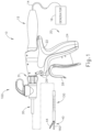
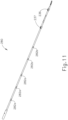
- FIG. 1 shows an exemplary ultrasonic surgical instrument (10). At least part of instrument (10) may be constructed and operable in accordance with at least some of the teachings of any of the various patents, patent application publications, and patent applications that are cited herein. As described therein and as will be described in greater detail below, instrument (10) is operable to cut tissue and seal or weld tissue (e.g., a blood vessel, etc.) substantially simultaneously.
- tissue and seal or weld tissue e.g., a blood vessel, etc.
- instrument (10) may have various structural and functional similarities with the HARMONIC ACE ® Ultrasonic Shears, the HARMONIC WAVE ® Ultrasonic Shears, the HARMONIC FOCUS ® Ultrasonic Shears, and/or the HARMONIC SYNERGY ® Ultrasonic Blades. Furthermore, instrument (10) may have various structural and functional similarities with the devices taught in any of the other references that are cited herein.
- Instrument (10) of the present example comprises a handle assembly (20), a shaft assembly (30), and an end effector (40).
- Handle assembly (20) comprises a body (22) including a pistol grip (24) and a pair of buttons (26).
- Handle assembly (20) also includes a trigger (28) that is pivotable toward and away from pistol grip (24). It should be understood, however, that various other suitable configurations may be used, including but not limited to a scissor grip configuration.
- End effector (40) includes an ultrasonic blade (160) and a pivoting clamp arm (44).
- Clamp arm (44) is coupled with trigger (28) such that clamp arm (44) is pivotable toward ultrasonic blade (160) in response to pivoting of trigger (28) toward pistol grip (24); and such that clamp arm (44) is pivotable away from ultrasonic blade (160) in response to pivoting of trigger (28) away from pistol grip (24).
- trigger (28) Various suitable ways in which clamp arm (44) may be coupled with trigger (28) will be apparent to those of ordinary skill in the art in view of the teachings herein.
- one or more resilient members are used to bias clamp arm (44) and/or trigger (28) to the open position shown in FIG. 1 .
- An ultrasonic transducer assembly (12) extends proximally from body (22) of handle assembly (20).
- Transducer assembly (12) is coupled with a generator (16) via a cable (14), such that transducer assembly (12) receives electrical power from generator (16).
- Piezoelectric elements in transducer assembly (12) convert that electrical power into ultrasonic vibrations.
- Generator (16) may include a power source and control module that is configured to provide a power profile to transducer assembly (12) that is particularly suited for the generation of ultrasonic vibrations through transducer assembly (12).
- generator (16) may comprise a GEN 300 sold by Ethicon Endo-Surgery, Inc. of Cincinnati, Ohio.
- generator (16) may be constructed in accordance with at least some of the teachings of U.S. Pub. No. 2011/0087212, entitled “Surgical Generator for Ultrasonic and Electrosurgical Devices,” published April 14, 2011 . It should also be understood that at least some of the functionality of generator (16) may be integrated into handle assembly (20), and that handle assembly (20) may even include a battery or other on-board power source such that cable (14) is omitted. Still other suitable forms that generator (16) may take, as well as various features and operabilities that generator (16) may provide, will be apparent to those of ordinary skill in the art in view of the teachings herein.
- end effector (40) of the present example comprises clamp arm (44) and ultrasonic blade (160).
- Clamp arm (44) includes a clamp pad (46) that is secured to the underside of clamp arm (44), facing blade (160).
- Clamp pad (46) may comprise polytetrafluoroethylene (PTFE) and/or any other suitable material(s).
- Clamp arm (44) is pivotally secured to a distally projecting tongue (43) of an upper distal shaft element (172), which is fixedly secured within a distal portion of a distal outer sheath (33).
- Clamp arm (44) is operable to selectively pivot toward and away from blade (160) to selectively clamp tissue between clamp arm (44) and blade (160).
- a pair of arms (156) extend transversely from clamp arm (44) and are pivotally secured to a lower distal shaft element (170), which is slidably disposed within the distal portion of distal outer sheath (33).
- a cable (174) is secured to lower distal shaft element (170).
- Cable (174) is operable to translate longitudinally relative to an articulation section (130) of shaft assembly (30) to selectively pivot clamp arm (44) toward and away from blade (160).
- cable (174) is coupled with trigger (28) such that cable (174) translates proximally in response to pivoting of trigger (28) toward pistol grip (24), and such that clamp arm (44) thereby pivots toward blade (160) in response to pivoting of trigger (28) toward pistol grip (24).
- cable (174) translates distally in response to pivoting of trigger (28) away from pistol grip (24), such that clamp arm (44) pivots away from blade (160) in response to pivoting of trigger (28) away from pistol grip (24).
- Clamp arm (44) may be biased toward the open position, such that (at least in some instances) the operator may effectively open clamp arm (44) by releasing a grip on trigger (28).
- Lower distal shaft element (170) comprises a pair of distal flanges (171, 173) extending from a semi-circular base (168). Flanges (171, 173) each comprise a respective opening (175, 177).
- Clamp arm (44) is rotatably coupled to lower distal shaft element (170) via a pair of inwardly extending integral pins (41, 45). Pins (41, 45) extend inwardly from arms (156) of clamp arm (44) and are rotatably disposed within respective openings (175, 177) of lower distal shaft element (170). As shown in FIGS.
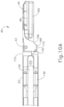
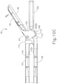
- longitudinal translation of cable (174) causes longitudinal translation of lower distal shaft element (170) between a proximal position ( FIG. 10A ) and a distal position ( FIG. 10C ).
- Longitudinal translation of lower distal shaft element (170) causes rotation of clamp arm (44) between a closed position ( FIG. 10A ) and an open position ( FIG. 10C ).
- Blade (160) of the present example is operable to vibrate at ultrasonic frequencies in order to effectively cut through and seal tissue, particularly when the tissue is being compressed between clamp pad (46) and blade (160).
- Blade (160) is positioned at the distal end of an acoustic drivetrain.
- This acoustic drivetrain includes transducer assembly (12) and an acoustic waveguide (180).
- Acoustic waveguide (180) comprises a flexible portion (166).
- Transducer assembly (12) includes a set of piezoelectric discs (not shown) located proximal to a horn (not shown) of waveguide (180).
- the piezoelectric discs are operable to convert electrical power into ultrasonic vibrations, which are then transmitted along waveguide (180), including flexible portion (166) of waveguide (180) to blade (160) in accordance with known configurations and techniques.
- this portion of the acoustic drivetrain may be configured in accordance with various teachings of various references that are cited herein.
- flexible portion (166) of waveguide (180) includes a distal flange (136), a proximal flange (138), and a narrowed section (164) located between flanges (136, 138).
- flanges (136, 138) are located at positions corresponding to nodes associated with resonant ultrasonic vibrations communicated through flexible portion (166) of waveguide (180).
- Narrowed section (164) is configured to allow flexible portion (166) of waveguide (180) to flex without significantly affecting the ability of flexible portion (166) of waveguide (180) to transmit ultrasonic vibrations.
- narrowed section (164) may be configured in accordance with one or more teachings of U.S. Pub. No.
- waveguide (180) may be configured to amplify mechanical vibrations transmitted through waveguide (180).
- waveguide (180) may include features operable to control the gain of the longitudinal vibrations along waveguide (180) and/or features to tune waveguide (180) to the resonant frequency of the system.
- waveguide (180) may be mechanically and acoustically coupled with transducer assembly (12) will be apparent to those of ordinary skill in the art in view of the teachings herein.
- the distal end of blade (160) is located at a position corresponding to an anti-node associated with resonant ultrasonic vibrations communicated through flexible portion (166) of waveguide (180), in order to tune the acoustic assembly to a preferred resonant frequency f o when the acoustic assembly is not loaded by tissue.
- the distal end of blade (160) is configured to move longitudinally in the range of, for example, approximately 10 to 500 microns peak-to-peak, and in some instances in the range of about 20 to about 200 microns at a predetermined vibratory frequency f o of, for example, 55.5 kHz.
- transducer assembly (12) of the present example When transducer assembly (12) of the present example is activated, these mechanical oscillations are transmitted through waveguide (180) to reach blade (160), thereby providing oscillation of blade (160) at the resonant ultrasonic frequency.
- the ultrasonic oscillation of blade (160) may simultaneously sever the tissue and denature the proteins in adjacent tissue cells, thereby providing a coagulative effect with relatively little thermal spread.
- an electrical current may also be provided through blade (160) and clamp arm (44) to also cauterize the tissue.
- Shaft assembly (30) of the present example extends distally from handle assembly (20).
- shaft assembly (30) includes distal outer sheath (33) and a proximal outer sheath (32) that enclose clamp arm (44) drive features and the above-described acoustic transmission features.
- Shaft assembly (30) further includes an articulation section (130), which is located at a distal portion of shaft assembly (30), with end effector (40) being located distal to articulation section (130).
- a knob (31) is secured to a proximal portion of proximal outer sheath (32).
- Knob (31) is rotatable relative to body (22), such that shaft assembly (30) is rotatable about the longitudinal axis defined by outer sheath (32), relative to handle assembly (20). Such rotation may provide rotation of end effector (40), articulation section (130), and shaft assembly (30) unitarily. Of course, rotatable features may simply be omitted if desired.
- Articulation section (130) is operable to selectively position end effector (40) at various lateral deflection angles relative to a longitudinal axis defined by outer sheath (32).
- Articulation section (130) may take a variety of forms.
- articulation section (130) may be configured in accordance with one or more teachings of U.S. Pub. No. 2012/0078247 .
- articulation section (130) may be configured in accordance with one or more teachings of U.S. Pub. No. 2014/0005701 and/or U.S. Pub. No. 2014/0114334 .
- Various other suitable forms that articulation section (130) may take will be apparent to those of ordinary skill in the art in view of the teachings herein.
- articulation section (130) of this example comprises a set of three retention collars (133) and a pair of ribbed body portions (132, 134), with a pair of articulation bands (140, 142) extending along respective channels (135, 137) defined between interior surfaces of retention collars (133) and exterior surfaces of ribbed body portions (132, 134).
- Ribbed body portions (132, 134) are longitudinally positioned between flanges (136, 138) of flexible portion (166) of waveguide (180). In some versions, ribbed body portions (132, 134) snap together about flexible portion (166) of waveguide (180). Ribbed body portions (132, 134) are configured to flex with flexible portion (166) of waveguide (180) when articulation section (130) bends to achieve an articulated state.
- FIG. 3 shows ribbed body portions (132, 134) in greater detail.
- ribbed body portions (132, 134) are formed of a flexible plastic material, though it should be understood that any other suitable material may be used.
- Ribbed body portion (132) comprises a set of three ribs (150) that are configured to promote lateral flexing of ribbed body portion (132). Of course, any other suitable number of ribs (150) may be provided. Ribbed body portion (132) also defines a channel (135) that is configured to receive articulation band (140) while allowing articulation band (140) to slide relative to ribbed body portion (132).
- ribbed body portion (134) comprises a set of three ribs (152) that are configured to promote lateral flexing of ribbed body portion (134). Of course, any other suitable number of ribs (152) may be provided. Ribbed body portion (134) also defines a channel (137) that is configured to receive articulation band (142) while allowing articulation band (142) to slide relative to ribbed body portion (137).
- ribbed body portions (132, 134) are laterally interposed between articulation bands (140, 142) and flexible portion (166) of waveguide (180). Ribbed body portions (132, 134) mate with each other such that they together define an internal passage sized to accommodate flexible portion (166) of waveguide (180) without contacting waveguide (180).
- a pair of complementary distal notches (131A, 131B) formed in ribbed body portions (132, 134) align to receive a pair of inwardly projecting resilient tabs (38) of distal outer sheath (33).
- This engagement between tabs (37) and notches (139A, 139B) longitudinally secures ribbed body portions (132, 134) relative to proximal outer sheath (32).
- any other suitable kinds of features may be used to couple ribbed body portions (132, 134) with proximal outer sheath (32) and/or distal outer sheath (33).
- articulation bands (140, 142) are unitarily secured to upper distal shaft element (172).
- articulation bands (140, 142) translate longitudinally in an opposing fashion, this will cause articulation section (130) to bend, thereby laterally deflecting end effector (40) away from the longitudinal axis of shaft assembly (30) from a straight configuration as shown in FIG. 6A to an articulated configuration as shown in FIG. 6B .
- end effector (40) will be articulated toward the articulation band (140, 142) that is being pulled proximally.
- the other articulation band (140, 142) may be pulled distally by upper distal shaft element (172).
- the other articulation band (140, 142) may be driven distally by an articulation control.
- Ribbed body portions (132, 134) and narrowed section (164) are all sufficiently flexible to accommodate the above-described articulation of end effector (40).
- flexible acoustic waveguide (166) is configured to effectively communicate ultrasonic vibrations from waveguide (180) to blade (160) even when articulation section (130) is in an articulated state as shown in FIG. 6B .
- each flange (136, 138) of waveguide (180) includes a respective pair of opposing flats (192, 196).
- Flats (192, 196) are oriented along vertical planes that are parallel to a vertical plane extending through narrowed section (164) of flexible portion (166).
- Flats (192, 196) are configured to provide clearance for articulation bands (140, 142).
- flats (196) of proximal flange (138) accommodate articulation bands (140, 142) between proximal flange (138) and the inner diameter of proximal outer sheath (32): while flats (192) of distal flange (136) accommodate articulation bands (140, 142) between distal flange (136) and the inner diameter of distal outer sheath (33).
- flats (192, 196) could be substituted with a variety of features, including but not limited to slots, channels, etc., with any suitable kind of profile (e.g., square, flat, round, etc.).
- flats (192, 196) are formed in a milling process, though it should be understood that any other suitable process(es) may be used.
- waveguide (180) may include flats formed in accordance with at least some of the teachings of U.S. Pat. App. No. 13/868,336, entitled “Ultrasonic Device for Cutting and Coagulating,” filed April 23, 2013 .
- outer rings (133) are located at longitudinal positions corresponding to ribs (150, 152), such that three rings (133) are provided for three ribs (150, 152).
- Articulation band (140) is laterally interposed within channel (135) between rings (133) and ribbed body portion (132); while articulation band (142) is laterally interposed within channel (137) between rings (133) and ribbed body portion (134).
- Rings (133) are configured to keep articulation bands (140, 142) in a parallel relationship, particularly when articulation section (130) is in a bent configuration (e.g., similar to the configuration shown in FIG. 6B ).
- rings (133) may retain articulation band (140) such that articulation band (140) follows a curved path that complements the curved path followed by articulation band (142).
- channels (135, 137) are sized to accommodate respective articulation bands (140, 142) in such a way that articulation bands (140, 142) may still freely slide through articulation section (130), even with rings (133) being secured to ribbed body portions (150, 152).
- rings (133) may be secured to ribbed body portions (132, 134) in various ways, including but not limited to interference fitting, adhesives, welding, etc.
- articulation bands (140, 142) When articulation bands (140, 142) are translated longitudinally in an opposing fashion, a moment is created and applied to a distal end of distal outer sheath (33) via upper distal shaft element (172). This causes articulation section (130) and narrowed section (164) of flexible portion (166) of waveguide (180) to articulate, without transferring axial forces in articulation bands (140, 142) to waveguide (180). It should be understood that one articulation band (140, 142) may be actively driven distally while the other articulation band (140, 142) is passively permitted to retract proximally.
- one articulation band (140, 142) may be actively driven proximally while the other articulation band (140, 142) is passively permitted to advance distally.
- one articulation band (140, 142) may be actively driven distally while the other articulation band (140, 142) is actively driven proximally.
- articulation bands (140, 142) may be driven will be apparent to those of ordinary skill in the art in view of the teachings herein.
- an articulation control assembly (100) is secured to a proximal portion of outer sheath (32).
- Articulation control assembly (100) comprises a housing (110) and a rotatable knob (120).
- Housing (110) comprises a pair of perpendicularly intersecting cylindrical portions (112, 114).
- Knob (120) is rotatably disposed within a first hollow cylindrical portion (112) of housing (110) such that knob (120) is operable to rotate within cylindrical portion (112) of housing (110).
- Shaft assembly (30) is slidably and rotatably disposed within a second cylindrical portion (114).
- Shaft assembly (30) comprises a pair of translatable members (161, 162), both of which extend slidably and longitudinally through the proximal portion of outer sheath (32).
- Translatable members (161, 162) are longitudinally translatable within second cylindrical portion (114) between a distal position and a proximal position.
- Translatable members (161, 162) are mechanically coupled with respective articulation bands (140, 142) such that longitudinal translation of translatable member (161) causes longitudinal translation of articulation band (140), and such that longitudinal translation of translatable member (162) causes longitudinal translation of articulation band (142).
- Knob (120) comprises a pair of pins (122, 124) extending downwardly from a bottom surface of knob (120).
- Pins (122, 124) extend into second cylindrical portion (114) of housing (110) and are rotatably and slidably disposed within a respective pair of channels (163, 164) formed in top surfaces of translatable members (161, 162).
- Channels (163, 164) are positioned on opposite sides of an axis of rotation of knob (120), such that rotation of knob (120) about that axis causes opposing longitudinal translation of translatable members (161, 162).
- rotation of knob (120) in a first direction causes distal longitudinal translation of translatable member (161) and articulation band (140), and proximal longitudinal translation of translatable member (162) and articulation band (142); and rotation of knob (120) in a second direction causes proximal longitudinal translation of translatable member (161) and articulation band (140), and distal longitudinal translation of translatable member (162) and articulation band (142).
- rotation of rotation knob (120) causes articulation of articulation section (130).
- Housing (110) of articulation control assembly (100) comprises a pair of set screws (111, 113) extending inwardly from an interior surface of first cylindrical portion (112). With knob (120) rotatably disposed within first cylindrical portion (112) of housing (110), set screws (111, 113) are slidably disposed within a pair of arcuate channels (121, 123) formed in knob (120). Thus, it should be understood that rotation of knob (120) will be limited by movement of set screws (111, 113) within channels (121, 123). Set screws (111, 113) also retain knob (120) in housing (110), preventing knob (120) from traveling vertically within first cylindrical portion (112) of housing (110).
- first cylindrical portion (112) of housing (110) comprises a first angular array of teeth (116) and a second angular array of teeth (118) formed in an interior surface of first cylindrical portion (112).
- Rotation knob (120) comprises a pair of outwardly extending engagement members (126, 128) that are configured to engage teeth (116, 118) of first cylindrical portion (112) in a detent relationship to thereby selectively lock knob (120) in a particular rotational position.
- the engagement of engagement members (126, 128) with teeth (116, 118) may be overcome by a user applying sufficient rotational force to knob (120); but absent such force, the engagement will suffice to maintain the straight or articulated configuration of articulation section (130). It should therefore be understood that the ability to selectively lock knob (120) in a particular rotational position lock will enable an operator to selectively lock articulation section (130) in a particular deflected position relative to the longitudinal axis defined by outer sheath (32).
- articulation section (130) of shaft assembly (30) is operable to achieve articulation angles up to between approximately 15° and approximately 30°, both relative to the longitudinal axis of shaft assembly (30) when shaft assembly (30) is in a straight (non-articulated) configuration.
- articulation section (130) may be operable to achieve any other suitable articulation angles.
- narrowed section (164) of waveguide (180) has a thickness between approximately 0.25mm (0.01 inches) and approximately 0.51mm (0.02 inches). Alternatively, narrowed section (164) may have any other suitable thickness. Also in some versions, narrowed section (164) has a length of between approximately 10mm (0.4 inches) and approximately 17mm (0.65 inches). Alternatively, narrowed section (164) may have any other suitable length. It should also be understood that the transition regions of waveguide (180) leading into and out of narrowed section (164) may be quarter rounded, tapered, or have any other suitable configuration.
- flanges (136, 138) each have a length between approximately 0.25mm (0.1 inches) and approximately 0.51mm (0.2 inches). Alternatively, flanges (136, 138) may have any other suitable length. It should also be understood that the length of flange (136) may differ from the length of flange (138). Also in some versions, flanges (136, 138) each have a diameter between approximately 4.45mm (0.175 inches) and approximately 5.1mm (0.2 inches). Alternatively, flanges (136, 138) may have any other suitable outer diameter. It should also be understood that the outer diameter of flange (136) may differ from the outer diameter of flange (138).
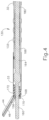
- FIGS. 11-13 show an exemplary alternative waveguide (280) that may be readily incorporated into instrument (10), particularly, into an acoustic drivetrain of instrument (10).
- Waveguide (280) of the present example includes a blade (260) , which is operable to vibrate at ultrasonic frequencies in order to effectively cut through and seal tissue, particularly when the tissue is being compressed between blade (260) and another portion of an end effector, such as a curved version of clamp pad (46) of end effector (40).
- blade (260) is curved at a bend angle "0" relative to a longitudinal axis of waveguide (280).
- the acoustic drivetrain includes transducer assembly (12) and acoustic waveguide (280).
- Acoustic waveguide (280) comprises a flexible portion (266).
- Transducer assembly (12) includes a set of piezoelectric discs (not shown) located proximal to a horn (not shown) of waveguide (280). The piezoelectric discs are operable to convert electrical power into ultrasonic vibrations, which are then transmitted along waveguide (280), including flexible portion (266) of waveguide (280), to blade (260) in accordance with known configurations and techniques.
- this portion of the acoustic drivetrain may be configured in accordance with various teachings of various references that are cited herein.
- Waveguide (280) includes a distal flange (236), a proximal flange (238), and a narrowed section (264) located between flanges (236, 238).
- Waveguide (280) includes longitudinally extending notches that are formed in the waveguide flanges to accommodate cable (274), which is discussed in more detail below. Cable is received in the lower notches (not shown); and the upper notches (237, 239) are formed to provide balance (i.e., to compensate for the presence of the lower notches).
- Waveguide (280) includes a tapered region (239) between distal flange (236) and blade (260).
- flanges (236, 238) are located at positions corresponding to nodes associated with resonant ultrasonic vibrations communicated through waveguide (280).
- Narrowed section (264) is configured to allow flexible portion (266) of waveguide (280) to flex without significantly affecting the ability of flexible portion (266) of waveguide (280) to transmit ultrasonic vibrations.
- narrowed section (264) may be configured in accordance with one or more teachings of U.S. Pub. No. 2014/0005701 and/or U.S. Pub. No. 2014/0114334 .
- waveguide (280) may be configured to amplify mechanical vibrations transmitted through waveguide (280).
- waveguide (280) may include features operable to control the gain of the longitudinal vibrations along waveguide (280) and/or features to tune waveguide (280) to the resonant frequency of the system.
- waveguide (280) includes a plurality of opposing pairs of longitudinally spaced, laterally presented notches (282a, 282b).
- each notch (282a) of the three most proximal pairs of notches (282a) has a longer length than each notch (282b) of the two most distal pairs of notches (282b).
- Notches (282a, 282b) are provided, at least in part, to assist in controlling the vibratory properties of the waveguide (280), which are different in waveguide (280) than in waveguide (180) due in part to the curved configuration of blade (260).
- waveguide (280) may be mechanically and acoustically coupled with transducer assembly (12) will be apparent to those of ordinary skill in the art in view of the teachings herein.
- Each flange (236, 238) of waveguide (280) includes a respective pair of opposing, laterally presented flats (292, 296).
- Flats (292, 296) are oriented along vertical planes that are parallel to a vertical plane extending through narrowed section (264) of flexible portion (266).
- Flats (296) are configured to provide clearance for articulation bands (212, 214).
- flats (296) of proximal flange (238) accommodate articulation bands (214) between proximal flange (138) and the inner diameter of proximal outer sheath (204).
- articulation bands (212, 214) are coupled to waveguide (280) at a point proximal to distal flange (236).
- flats (292, 296) could be substituted with a variety of features, including but not limited to slots, channels, etc., with any suitable kind of profile (e.g., square, flat, round, etc.).
- flats (292, 296) are formed in a milling process, though it should be understood that any other suitable process(es) may be used.
- waveguide (280) may include flats formed in accordance with at least some of the teachings of U.S. Pub. No. 2013/0289592, entitled "Ultrasonic Device for Cutting and Coagulating,” published October 31, 2013 .
- the distal end of blade (260) is located at a position corresponding to an anti-node associated with resonant ultrasonic vibrations communicated through flexible portion (266) of waveguide (280), in order to tune the acoustic assembly to a preferred resonant frequency f o when the acoustic assembly is not loaded by tissue.
- the distal end of blade (260) is configured to move longitudinally in the range of, for example, approximately 10 to 500 microns peak-to-peak, and in some instances in the range of about 20 to about 200 microns at a predetermined vibratory frequency f o of, for example, 55.5 kHz.
- transducer assembly (12) of the present example When transducer assembly (12) of the present example is activated, these mechanical oscillations are transmitted through waveguide (280) to reach blade (260), thereby providing oscillation of blade (260) at the resonant ultrasonic frequency.
- the ultrasonic oscillation of blade (260) may simultaneously sever the tissue and denature the proteins in adjacent tissue cells, thereby providing a coagulative effect with relatively little thermal spread.
- an electrical current may also be provided through blade (260) and clamp arm (44) to also cauterize the tissue.
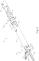
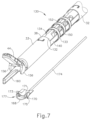
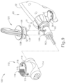
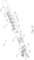
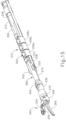
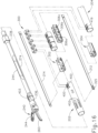
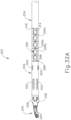
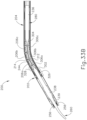
- FIGS. 14-16 and 32A-33B show an exemplary alternative shaft assembly (200) and end effector (240) that may be readily incorporated into instrument (10).
- shaft assembly (200) and end effector are configured to accommodate for the properties of curved blade (260), as discussed in more detail below.
- Shaft assembly (200) of this example comprises a distal outer sheath (202), a proximal outer sheath (204), and a plurality of flex rings (206) that form a portion of an articulation section (210).
- articulation section (130) is configured to articulate in two lateral directions relative to the longitudinal axis of shaft assembly (30)
- articulation section (210) of the present example is configured to articulate in only one direction relative to a longitudinal axis of shaft assembly (200).
- articulation section (210) is allowed to articulate in one lateral direction, but is substantially prevented from articulating in the opposite lateral direction.
- Articulation section (210) is operable to selectively position end effector (240) at various lateral deflection angles, in one direction, relative to a longitudinal axis defined by proximal outer sheath (204).
- the direction in which articulation section (210) is permitted to articulate is the same direction which curved blade (260) bends away from the axis (at bend angle ( ⁇ )).
- End effector (240) includes blade (260) and a pivoting clamp arm (244) having a clamp pad (245).
- clamp arm (244) and clamp pad (245) are curved at a bend angle that is substantially similar to the bend angle ( ⁇ ) of blade (260).
- End effector (240) is configured to operate substantially similar to end effector (40) discussed above except for the differences discussed below.
- clamp arm (244) of end effector (240) is operable to compress tissue against blade (260).
- blade (260) is activated while clamp arm (244) compresses tissue against blade (260)
- end effector (240) simultaneously severs the tissue and denatures the proteins in adjacent tissue cells, thereby providing a coagulative effect.
- Clamp arm (244) is operable to selectively pivot toward and away from blade (242) to selectively clamp tissue between clamp pad (245) and blade (260), in a manner substantially similar to clamp arm (44).
- Clamp arm (244) is coupled to a trigger (e.g., trigger (28)) such that clamp arm (244) is pivotable toward ultrasonic blade (260) in response to pivoting of trigger (28) toward pistol grip (24); and such that clamp arm (244) is pivotable away from ultrasonic blade (260) in response to pivoting of trigger (28) away from pistol grip (24).
- a cable (274) is secured to a lower distal shaft element (270).
- Cable (274) is operable to translate longitudinally relative to an articulation section (210) of shaft assembly (200) to selectively pivot clamp arm (244) toward and away from blade (260).
- cable (274) is coupled with trigger (28) such that cable (274) translates proximally in response to pivoting of trigger (28) toward pistol grip (24), and such that clamp arm (244) thereby pivots toward blade (260) in response to pivoting of trigger (28) toward pistol grip (24).
- cable (274) translates distally in response to pivoting of trigger (28) away from pistol grip (24), such that clamp arm (244) pivots away from blade (260) in response to pivoting of trigger (28) away from pistol grip (24).
- Clamp arm (244) may be biased toward the open position, such that (at least in some instances) the operator may effectively open clamp arm (244) by releasing a grip on trigger (28).
- trigger Various suitable ways in which clamp arm (244) may be coupled with trigger (28) will be apparent to those of ordinary skill in the art in view of the teachings herein.
- cable (274) is secured to a proximal end of a lower distal shaft element (270), which is configured in a manner substantially similar to lower distal shaft element (170).
- lower distal shaft element (270) comprises a pair of distal flanges (not shown) extending from a semi-circular base. The flanges each comprise a respective opening (not shown).
- Clamp arm (244) is rotatably coupled to lower distal shaft element (270) via a pair of inwardly extending integral pins (not shown). The pins extend inwardly from arms (256) of clamp arm (244) and are rotatably disposed within respective openings of lower distal shaft element (270). In a manner similar to that shown in FIGS.
- longitudinal translation of cable (274) causes longitudinal translation of lower distal shaft element (270) between a proximal position and a distal position.
- Longitudinal translation of lower distal shaft element (270) causes rotation of clamp arm (244) between a closed position and an open position.
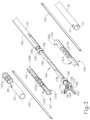
- Shaft assembly (200) further comprises a pair of articulation bands (212, 214). Distal ends of articulation bands (212, 214) are secured to distal flex member (302) of articulation section (210). Articulation bands (212, 214) are configured to operate substantially similar to articulation bands (140, 142) discussed above except for the differences discussed below. In particular, as shown best in FIGS. 32A-33B , articulation bands (212, 214) are permitted to cause articulation of articulation section (210) in substantially only one direction, as discussed in more detailed below.
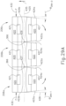
- articulation section (210) comprises a distal flex member (302), a proximal flex member (304), and a plurality of flex base members (306a-c). Articulation section (210) further comprises distal outer sheath (202), a proximal outer sheath (204), and flex rings (206a-c). Articulation section (210) also includes a flexible collar (300) that is configured to operably couple certain components of the articulation section (210) to one another, as discussed in more detail below. Distal flex member (302) t is operably coupled to the distal ends of a respective articulation band (212, 214).
- Flex base members (304a-c) are positioned proximally relative to the distal flex member (302), and proximal flex member (304) positioned proximal of flex base members (306a-c).
- Distal flex member (302), proximal flex member (304), and flex base members (306a-c) collectively define opposing channels (308, 310) for receiving articulation bands (212, 214), respectively.
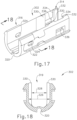
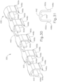
- FIGS. 17-18 show distal flex member (302) of the present example in more detail.
- distal flex member (302) includes a proximal end (314), a distal end (316), and a generally U-shaped body (318) that defines a space (319) configured for receiving at least a portion of waveguide (280).
- a bottom portion of distal flex member (302) includes a longitudinally extending recess (320) that is configured to receive cable (274).
- Each side of distal flex member (302) includes a channel (322) that is shaped and configured for receiving a distal end of a respective articulation band (212, 214).
- Each channel (322) includes an aperture (324) that is configured to receive a portion of a fastener (325) ( FIG. 15 ) for coupling a respective articulation band (212, 214) to a side of the distal flex member (302).
- fastener (325) may comprise a pin, a rivet, and/or any other suitable kind of structure
- Space (319) for receiving waveguide (280) includes a first dimensioned portion (326) that receives a distal portion of waveguide and a second dimensioned portion (328), which includes a smaller dimension than first dimensioned portion (326).
- Second dimensioned portion (328) is configured to receive narrowed section (264) of waveguide (280).
- distal flex member (302) does not contact waveguide (280).
- Second dimensioned portion (326) is defined by a pair of opposing angled flanges (330) which extend radially inwardly toward a central longitudinal axis of distal flex member (302). Angled flanges (330) define a tapered transition portion between the first dimensioned portion (326) and second dimensioned portion (328).
- Second dimensioned portion (328) is further defined by a pair of flanges (332), which also extend radially inwardly toward the central longitudinal axis of distal flex member (302), at the proximal end (314) of distal flex member (302).
- Flanges (330, 332) define a pair of opposing slots (334) that extend along a plane that is parallel to the longitudinal axis of distal flex member.
- Each slot (334) includes an aperture (336).
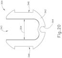
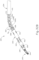
- FIGS. 19-20 show proximal flex member (304) of the present example in more detail.
- proximal flex member (304) includes a proximal end (338), a distal end (340) and a generally U-shaped body (342) that defines a space (343) configured for receiving at least a portion of waveguide (280).
- a bottom portion of proximal flex member (302) includes a longitudinal recess (344) that is configured to receive cable (274).
- Each side of proximal flex member (304) includes a channel (346) that is shaped and configured for receiving portion of a respective articulation band (212, 214) (and which forms a portion of channels (308, 310)).
- Each channel (346) is defined in part by an upper, shelf (348) and a lower shelf (350).
- the space (343) of proximal flex member (304) for receiving waveguide (280) includes a first dimensioned portion (352) that receives a portion of waveguide (280) and a second dimensioned portion (354), which includes a smaller dimension than first dimensioned portion (326).
- Second dimensioned portion (354) is configured to receive narrowed section (264) of waveguide (280), though proximal flex member (304) does not contact waveguide (280).
- Second dimensioned portion (354) is defined by a pair of opposing angled flanges (356) which extend radially inwardly toward a central longitudinal axis of proximal flex member (304).
- Angled flanges (356) define a tapered transition portion between the first dimensioned portion (352) and second dimensioned portion (354).
- Second dimensioned portion (354) is further defined by a pair of flanges (358), which also extend radially inwardly toward the central longitudinal axis of proximal flex member (304), at the distal end (340) of proximal flex member (304).
- Flanges (356, 358) define a pair of opposing slots (360). Each slot (360) includes a generally rectangular aperture (362).
- flex base members (306a-c) may be separate, individual members.
- body (364) is generally U-shaped and defines a space (368) configured for receiving at least a portion of waveguide (280). However, body (364) does not contact waveguide (280).
- a bottom portion of each flex base member (306a-c) includes a longitudinal recess (370) configured to receive cable (274).
- Each side of each base member (306a-c) includes a radially outwardly extending shelf (372), each of which defines a boundary on each side of the base members (306a-c) for receiving a portion of a respective articulation band (212, 214).
- Each base member (306a-c) includes a respective pair of opposing distal flanges (374) and a respective pair of opposing proximal flanges (376) extending radially inwardly toward a central longitudinal axis of body (364).
- the distal and proximal flanges (374, 376) in each pair of flanges (374, 376) define a slot (378) therebetween.
- Each slot (378) includes a generally rectangular aperture (380).
- Each base member (306a-c) includes a respective first distal face portion (382a), a second distal face portion (382b), a first proximal face portion (384a), and a second proximal face portion (384b).
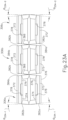
- base members (306a-c) are configured to transition to a flexed position from an unflexed position ( FIG. 23A ) when, for example, articulation bands (212, 214) are moved longitudinally relative to one another. In the unflexed position, there is a gap between adjacent first proximal and distal faces (384a, 382a); and between second proximal and distal faces (384b, 382b).
- First distal faces (382a) and second distal faces (382b) are disposed at an oblique angle ( ⁇ 23A-1 ) relative to an imaginary plane that is perpendicular to the longitudinal axis of base members (306a-c).
- First proximal edges (384a) and first proximal edges (384b) are disposed at an oblique angle ( ⁇ 23A-2 ) relative to an imaginary plane that is perpendicular to the longitudinal axis of base members (306a-c).
- angle ( ⁇ 23A-1 ) and angle ( ⁇ 23A-2 ) are substantially equal.
- the angle between adjacent first proximal and distal edges (384a, 382a) in an unflexed position; and between adjacent second proximal and distal edges (384b, 382b) in an unflexed position is ⁇ 23A-1 + ⁇ 23A-2 .
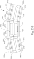
- base members (306a-c) are in a flexed position after pivoting in one direction relative to a central longitudinal axis about living hinges (366), such that first proximal faces (384a) substantially abut respective first distal faces (382a) of an adjoining base member (306a-c). It will be understood that in some versions, base members (306a-c) may pivot in an opposite direction, for example, such that second proximal faces (382b) substantially abut respective second distal faces (382b) of an adjoining base member (306a-c). However, in the present example, as will be understood from the discussion below, other components of articulation section (210) may effectively allow base members (306a-c) to pivot in only one direction. Various suitable ways in which flex base members (306a-c) may be configured will be apparent to those of ordinary skill in the art in view of the teachings herein.
- articulation section (210) of the present example also includes a distal outer sheath (202), a proximal outer sheath (204), and flex rings (206a-c) that at least partially surround other components of articulation section (210).
- distal outer sheath (202) of the present example more particularly comprises a proximal end (386), a distal end (388), and a lumen (390) extending therebetween.
- At least a first portion (392) of a proximal edge of distal outer sheath (202) extends along an imaginary plane (393) that is perpendicular to the longitudinal axis of distal outer sheath (202), while a second portion (394) of proximal edge extends at angle ( ⁇ 25 ) relative to plane (393).
- Distal outer sheath (202) of the present example further comprises a longitudinal channel (396) extending from the proximal edge (392) in a direction parallel to a longitudinal axis of distal outer sheath (202). Longitudinal channel (396) terminates at a transverse channel (398).
- Transverse channel (398) of the present example extends parallel to the plane (393) but perpendicular to longitudinal channel (396).
- Distal outer sheath (202) is coupled to waveguide (280) via an elastomeric ring (403), which is positioned about distal flange (236) of waveguide (280).
- elastomeric ring (403) which is positioned about distal flange (236) of waveguide (280).
- Distal outer sheath (202) of the present example further comprises a pair of apertures (400), which are generally rectangular in shape, and spaced laterally from one another and from longitudinal cutout (396).
- Distal outer sheath (202) further includes a plurality of circumferentially spaced obround apertures (402). As shown, in the present example, there are six obround apertures (402), but in other examples, there may be more or less than six obround apertures (402). Longitudinally between obround apertures (402) and proximal end (386), distal tube member includes a pair of angularly spaced, generally rectangular apertures (404).
- obround apertures (402) and proximal end (386) distal tube member includes a pair of angularly spaced, generally rectangular apertures (404).
- Proximal outer sheath (204) of the present example is suitable for incorporation into instrument (10) in a manner substantially similar to outer sheath (32).
- Proximal outer sheath (204) is substantially similar to outer sheath (32), except for the differences discussed herein.
- proximal outer sheath (204) includes a proximal end (not shown), a distal end (406), and a lumen (408) extending therebetween. As best seen in FIG.
- a first portion (410) of distal edge extends along an imaginary plane (411) that is perpendicular to the longitudinal axis of proximal outer sheath (204), while a second portion (412) of distal edge (410) extends at an oblique angle ( ⁇ 27 ) relative to plane (412).
- Proximal outer sheath (204) further comprises a longitudinal channel (414) extending from distal edge (410) in a direction parallel to a longitudinal axis of proximal outer sheath (204). Longitudinal channel (414) terminates at a transverse channel (416). Transverse channel (416) of the present example extends parallel to plane (412) but perpendicular relative to longitudinal channel (414).
- Proximal outer sheath (204) of the present example further comprises a pair of apertures (419), which are generally rectangular in shape, and spaced laterally from one another and from longitudinal cutout (414).
- proximal outer sheath (204) may be configured will be apparent to those of ordinary skill in the art in view of the teachings herein.
- distal, middle, and proximal flex rings (206a-c) are positioned between distal outer sheath (202) and proximal outer sheath (204) such that flex rings (206a-c), distal outer sheath (202), and proximal outer sheath (204) define at least a portion of a radially outward boundary of shaft assembly (200).
- Flex rings (206a-c) define a single, unitary body (364) comprising three members (306a-c), with living hinges (366) between adjoining flex rings (206a-c).
- flex rings (206a-c) may be separate, individual members. Referring also to FIGS.
- each flex ring (206a-c) includes a first portion (418) that is partially circular in cross-section and a pair of flanges (420).
- the flanges (420) of each pair of flanges (420) extend radially inwardly from each end of the first portion (418) toward one another, and along a plane extending parallel to a longitudinal axis of each flex ring (206).
- Each flange (420) includes a generally rectangular aperture (421) extending therethrough.
- Each flex ring (206a-c) includes a first distal edge portion (422a), second distal edge portion (422b), first proximal edge portion (424a), and second proximal edge portion (424b).
- first distal edge portion (422a) extends at an oblique angle relative to second distal edge portion (422b).
- Second distal edge portion (422b) of each flex ring (206a-c) extends along a first plane (426) that is perpendicular to the longitudinal axis of each flex ring (206a-c).
- first distal edge portion (422a) extends at an oblique angle ( ⁇ 29A-1 ) relative to a first plane (426) that is perpendicular to the longitudinal axis of each flex ring (206).
- first proximal edge portion (424a) extends at an oblique angle relative to second proximal edge portion (424b).
- Second proximal edge portion (424b) extends along a second plane (428) that is perpendicular to the longitudinal axis of each flex ring (206a-c).
- first proximal edge portion (424a) of each flex ring (206a-c) extends at an oblique angle ( ⁇ 29A-2 ) relative to its second proximal edge portion (424b).
- the distal most flex ring (206a) When assembled as shown in FIGS. 14-15 , the distal most flex ring (206a) is substantially abutted distally by distal outer sheath (202) (force represented by arrow (430) in FIG. 29A ), while the proximal most flex ring (206c) is substantially abutted proximally by proximal outer sheath (204) (force represented by arrow (432) in FIG. 29A ).
- Flex rings (206a-c) are configured to transition to a flexed position ( FIG. 29B ) from an unflexed position ( FIG. 29A ) when, for example, articulation bands (212, 214) are moved longitudinally relative to one another, as discussed in more detail below.
- second distal edge portions (424a) and second proximal edge portions (424b) interact with one another and with distal outer sheath (202) and proximal outer sheath (204) to act as positive stops to restrict pivoting of flex rings (206a-c) to a single direction.
- longitudinal axis (425) intersects the points of each flex ring (206a-c) where the respective first and second distal portions (422a, 422b) meet, and where the respective first and second proximal portions (424a, 424b) meet.
- flex rings are substantially prevented from pivoting along a path that is above axis (425) ("above” direction represented by arrow (435)). Therefore, in the present example, due to the operative coupling of flex rings (206a-c) to other components of articulation mechanism (210), articulation mechanism (210) is permitted to articulate in only one direction (opposite to arrow (435)) and may only pivot about axes (427, 429)).
- Flex rings (206a-c) are rigid in the present example such that any attempted articulation in the opposite direction does not substantially occur due to the material properties of flex rings (206a-c). That is, where articulation bands (212, 214) are moved in a manner that causes a moment in the opposite direction, the material properties (rigidity, stiffness, etc.) of flex rings (206a-c) are configured to prevent bending, buckling, compression, etc., of the flex rings (206a-c) that may cause a certain amount of articulation in the direction of arrow (435).
- Various suitable ways in which flex rings (206a-c) may be configured will be apparent to those of ordinary skill in the art in view of the teachings herein.
- FIGS. 14-16 and 30-33B show collar (300) of the present example.
- collar (300) is configured to operably couple certain components of the articulation section (210) to one another.
- Collar (300) of the present example is further configured to couple distal outer sheath (202) with proximal outer sheath (204).
- collar (434) includes a proximal end (436), and a distal end (438), and a body (440) extending therebetween.
- collar (300) includes a spine portion (442) extending along a longitudinal axis and five pairs of opposing legs (444a-e) extending from the spine portion (442).
- Collar (300) also includes an elongate rib (443) extending along the axis of the collar (300).
- Each of the five pairs of legs (444a-e) are spaced apart equally along a longitudinal axis of the collar (300). As shown, there are five pairs of opposing legs, but there may be more or less than five pairs of legs, and the pairs of opposing legs may or may not be equally spaced longitudinally.
- each pair of legs includes a first leg that extends away from the spine (442) in a first direction and a second leg extending away from the spine in second direction.
- Each of the first and second legs of each pair include curvilinear portions and are configured such that the first and second legs of each pair eventually extend parallel to one another.
- Each of the legs (444a-e) includes a respective snap-fit feature (446a-e) defining respective angled portions (448a-e) and lip portions (450a-e).
- angled portions (448a-e) are configured to act as cam members, in order to assist the collar (300) to be coupled with other components of the articulation section. More particularly, angled portions (448a-e) may act as cam members when being directed into respective slots and apertures, and legs (444a-e) may flex inwardly temporarily as collar (300) is being directed into engagement with certain components to provide a snap fit engagement.
- collar (300) may be configured will be apparent to those of ordinary skill in the art in view of the teachings herein
- proximal end (314) of distal flex member (302) substantially abuts flex base member (306a), particularly at the point where first distal portion (382a) meets second distal portion (382b).
- Distal end (340) of proximal flex member (304) substantially abuts flex base member (306c), particularly where first proximal portion (384a) meets second proximal portion (384b).
- flex base member (306b) is between flex base member (306a) and flex base member (306c).
- lumen (390) of distal tube member (302) coaxially receives distal flex member (302) such that slots (334) of distal flex member (302) generally align with apertures (400) of distal outer sheath (202).
- Legs (444a) extend into apertures (400) and along slots (334) such that lip portion (450a) engages a portion of aperture (336) and thereby secures collar (300), distal flex member (302), and distal outer sheath (202) to one another.
- Lumen (408) of proximal outer sheath (204) receives proximal flex member (304) such that slots (360) of proximal flex member (304) generally align with apertures (419) of proximal tube member.
- Legs (444e) extend into apertures (419) and along slots (360) such that lip portion (450e) engages a portion of aperture (362) and thereby secures collar (300), proximal flex member (304), and proximal outer sheath (204) to one another.
- Flex base members (306a-c) of the present example are coaxially received in flex rings (206a-c) such that flex base member (306a) is coincident with flex ring (206a), flex base member (306b) is coincident with flex ring (206b), and flex base member (306c) is coincident with flex ring (206c). Therefore, in such a configuration, apertures (421) of each flex ring (206a-c) generally align with slots (378) of a respective flex base member (306a-c).
- Legs (444b) extend into apertures (421) of flex ring (206a) and along slots (378) of flex base member (306a) such that lip portions (450b) engage a portion of a respective aperture (380).
- legs (444c) extend into apertures (421) of flex ring (206b) and along slots (378) of flex base member (306b) such that lip portions (450c) engage a portion of a respective aperture (380).
- legs (444d) extend into apertures of flex ring (206b) and along slots (378) of flex base member (306c) such that lip portions (450d) engage a portion of a respective aperture (380).
- first portion (392) of proximal edge of distal outer sheath (202) substantially abuts second distal portion (422b) of flex ring (206a).
- Second proximal portion (424b) of flex ring (206a) substantially abuts second distal portion (422b) of flex ring (206b).
- second proximal portion (424b) of flex ring (206b) substantially abuts second distal portion (422b) of flex ring (206c).
- Second proximal portion (424b) of flex ring (206b) substantially abuts first portion (210) of distal edge of proximal outer sheath (204).
- distal flex member (302) As articulation bands (212, 214) are moved longitudinally relative to one another, a moment is initially applied to distal flex member (302). Due to the distal flex member (302), flex base members (306a-c), proximal flex member (304), distal outer sheath (202), flex rings (206a-c), and proximal outer sheath (304) being operably coupled via collar (300) in the manner described herein, the moment applied to distal flex member (302) is transferred to the collar (300), distal flex member (302), flex base members (306a-c), proximal flex member (304), distal outer sheath (202), flex rings (206a-c), and proximal outer sheath (204).
- articulation section transitions (210) to an articulated configuration, as best shown in FIGS. 32B , 33B .
- articulation section (210) articulates in the same direction away from the longitudinal axis of instrument (10) as the direction of the bend angle ( ⁇ ) of blade (260).
- distal outer sheath (202) is pivoted relative to flex ring (206a) such that second portion (394) of distal edge of distal outer sheath (202) substantially abuts first distal portion (422a) of flex ring (206a).
- Flex ring (206a) is shown to be pivoted relative to flex ring (206b) such that first proximal portion (424a) of flex ring (206b) substantially abuts first distal portion (422a) of flex ring (206b).
- Flex ring (206b) is shown pivoted relative to flex ring (206c) such that first proximal portion (424a) of flex ring (206b) substantially abuts first distal portion (422a) of flex ring (206c).
- Flex ring (206c) is shown to be pivoted such that first proximal portion (424a) of flex ring (206c) substantially abuts second portion (412) of distal edge of proximal outer sheath (204).
- articulation section (210) may return to the unarticulated configuration shown in FIGS. 32A and 33A .
- engagement between adjacent edge portions (422b, 424b) will prevent articulation section (210) from articulating past longitudinal axis (425) in the direction of arrow (435).
- any of the versions of instruments described herein may include various other features in addition to or in lieu of those described above.
- any of the instruments described herein may also include one or more of the various features disclosed in any of the various references that are cited herein.
- teachings herein may be readily applied to any of the instruments described in any of the other references cited herein, such that the teachings herein may be readily combined with the teachings of any of the references cited herein in numerous ways.
- teachings herein may be readily applied to electrosurgical instruments, stapling instruments, and other kinds of surgical instruments.
- Other types of instruments into which the teachings herein may be incorporated will be apparent to those of ordinary skill in the art.
- Versions of the devices described above may have application in conventional medical treatments and procedures conducted by a medical professional, as well as application in robotic-assisted medical treatments and procedures.
- various teachings herein may be readily incorporated into a robotic surgical system such as the DAVINCI TM system by Intuitive Surgical, Inc., of Sunnyvale, California.
- DAVINCI TM system by Intuitive Surgical, Inc., of Sunnyvale, California.
- teachings herein may be readily combined with various teachings of U.S. Pat. No. 6,783,524, entitled "Robotic Surgical Tool with Ultrasound Cauterizing and Cutting Instrument," published August 31, 2004 .
- Versions described above may be designed to be disposed of after a single use, or they can be designed to be used multiple times. Versions may, in either or both cases, be reconditioned for reuse after at least one use. Reconditioning may include any combination of the steps of disassembly of the device, followed by cleaning or replacement of particular pieces, and subsequent reassembly. In particular, some versions of the device may be disassembled, and any number of the particular pieces or parts of the device may be selectively replaced or removed in any combination. Upon cleaning and/or replacement of particular parts, some versions of the device may be reassembled for subsequent use either at a reconditioning facility, or by a user immediately prior to a procedure.
- reconditioning of a device may utilize a variety of techniques for disassembly, cleaning/replacement, and reassembly. Use of such techniques, and the resulting reconditioned device, are all within the scope of the present application.
- versions described herein may be sterilized before and/or after a procedure.
- the device is placed in a closed and sealed container, such as a plastic or TYVEK bag.
- the container and device may then be placed in a field of radiation that can penetrate the container, such as gamma radiation, x-rays, or high-energy electrons.
- the radiation may kill bacteria on the device and in the container.
- the sterilized device may then be stored in the sterile container for later use.
- a device may also be sterilized using any other technique known in the art, including but not limited to beta or gamma radiation, ethylene oxide, or steam.
Landscapes
- Health & Medical Sciences (AREA)
- Surgery (AREA)
- Engineering & Computer Science (AREA)
- Life Sciences & Earth Sciences (AREA)
- Heart & Thoracic Surgery (AREA)
- Nuclear Medicine, Radiotherapy & Molecular Imaging (AREA)
- Mechanical Engineering (AREA)
- Biomedical Technology (AREA)
- Dentistry (AREA)
- Medical Informatics (AREA)
- Molecular Biology (AREA)
- Animal Behavior & Ethology (AREA)
- General Health & Medical Sciences (AREA)
- Public Health (AREA)
- Veterinary Medicine (AREA)
- Surgical Instruments (AREA)
- Ultra Sonic Daignosis Equipment (AREA)
Claims (12)
- Einrichtung (10) zum Operieren von Gewebe, die Einrichtung umfassend:(a) eine Körperbaugruppe (22);(b) einen Schaft (200), der sich distal von der Körperbaugruppe erstreckt, wobei der Schaft eine Längsachse definiert;(c) einen akustischen Wellenleiter (180, 280), wobei der Wellenleiter einen flexiblen Abschnitt (166, 266) umfasst;(d) einen mit dem Schaft gekoppelten Gelenkabschnitt (210), wobei ein Abschnitt des Gelenkabschnitts den flexiblen Abschnitt des Wellenleiters umschließt,
wobei der Gelenkabschnitt ferner umfasst:(i) ein erstes Element (212), und(ii) ein zweites Element (214), wobei das zweite Element in Längsrichtung relativ zum ersten Element verschiebbar ist;(e) einen Endeffektor (40, 240), umfassend eine Ultraschallklinge in akustischer Kommunikation mit dem Wellenleiter; und(f) eine Gelenkantriebsbaugruppe, die dazu dient, die Gelenkbewegung des Gelenkabschnitts anzutreiben, um dadurch den Endeffektor in einer ersten Richtung von der Längsachse abzulenken; wobeider Gelenkabschnitt (210) ferner ein distales Flexelement (302), ein proximales Flexelement (304) und eine Vielzahl von Flexbasiselementen (306a-c), die proximal relativ zum distalen Flexelement (302) und distal relativ zum proximalen Flexelement (304) positioniert sind; wobeidas distale Flexelement (302) funktionsfähig mit den distalen Enden des ersten und des zweiten Elements (212, 214) verbunden ist;
dadurch gekennzeichnet, dassdas distale Flexelement ein proximales Ende (314), ein distales Ende (316) und einen im Allgemeinen U-förmigen Körper (318) einschließt, der einen ersten Raum (319) definiert, der zum Aufnehmen von mindestens einem Abschnitt des Wellenleiters (280) konfiguriert ist;das proximale Flexelement (304) ein proximales Ende (338), ein distales Ende (340) und einen im Allgemeinen U-förmigen Körper (342) einschließt, der einen zweiten Raum (343) definiert, der zum Aufnehmen von mindestens einem Abschnitt des Wellenleiters (280) konfiguriert ist; unddie flexiblen Basiselemente (306a-c) einen im Allgemeinen U-förmigen Körper (364) und einen dritten Raum (368) definieren, der für die Aufnahme von mindestens einem Abschnitt des Wellenleiters (280) konfiguriert ist; wobeider erste, zweite und dritte Raum (310, 343, 368) den Wellenleiter so aufnehmen, dass das distale Flexelement (302), das proximale Flexelement (304) und die Flexbasiselemente (306a-c) den Wellenleiter (280) nicht berühren. - Einrichtung nach Anspruch 1, wobei jede Seite des distalen Flexelements (302) einen Kanal (322) einschließt, der so geformt und konfiguriert ist, dass er einen Abschnitt des jeweiligen ersten und zweiten Elements (212, 214) aufnimmt.
- Einrichtung nach Anspruch 1 oder 2, wobei jede Seite des distalen Flexelements (304) einen Kanal (346) einschließt, der so geformt und konfiguriert ist, dass er einen Abschnitt des jeweiligen ersten und zweiten Elements (212, 214) aufnimmt.
- Einrichtung nach einem der vorstehenden Ansprüche, wobei jede Seite jedes Basiselements (306a-306c) eine radial nach außen verlaufende Ablage (372) einschließt, die jeweils auf jeder Seite der Basiselemente (306a-c) eine Grenze zur Aufnahme eines Abschnitts des jeweiligen ersten und zweiten Elements (212, 214) bildet.
- Einrichtung nach einem der vorstehenden Ansprüche, wobei der Gelenkabschnitt einen positiven Anschlag (422b, 424b) einschließt, wobei der positive Anschlag konfiguriert ist, um eine Ablenkung des Endeffektors in eine zweite Richtung im Wesentlichen zu verhindern, wobei die zweite Richtung der ersten Richtung entgegengesetzt ist.
- Einrichtung nach Anspruch 5, wobei der Gelenkabschnitt eine Vielzahl von röhrenförmigen Elementen (206a-206c) umfasst, wobei der positive Anschlag an mindestens einem der röhrenförmigen Elemente (206a-206c) angeordnet ist.
- Einrichtung nach Anspruch 6, wobei der positive Anschlag eine Kante von mindestens einem der röhrenförmigen Elemente (206a-206c) umfasst.
- Einrichtung nach Anspruch 7, wobei die Kante senkrecht zur Längsachse des Schafts verläuft, wenn sich der Gelenkabschnitt in einer nicht gebogenen Konfiguration befindet.
- Einrichtung nach einem der vorstehenden Ansprüche, wobei der Gelenkabschnitt (210) eine flexible Manschette (300) mit einem parallel zur Längsachse des Schafts (30) verlaufenden Dornabschnitt (442) umfasst, wobei die flexible Manschette (300) konfiguriert ist, um den Schaft und den Gelenkabschnitt funktionsfähig miteinander zu verbinden.
- Einrichtung nach Anspruch 9, wobei die flexible Manschette (300) konfiguriert ist, um das distale Flexelement (302), das proximale Flexelement (304) und die Flexbasiselemente (306a-c) funktionsfähig miteinander zu verbinden.
- Einrichtung nach Anspruch 10, wobei die flexible Manschette (300) eine Vielzahl von Schenkeln (444a-e) umfasst, die quer zum Dornabschnitt (442) verlaufen, wobei mindestens einer der Schenkel (444a-e) so konfiguriert ist, dass er mit dem Schaft in Eingriff tritt, wobei mindestens ein Paar Schenkel (444a-e) so konfiguriert ist, dass er mit dem distalen Flexelement (302), dem proximalen Flexelement (304) und den Flexbasiselementen (306a-306c) in Eingriff tritt.
- Einrichtung nach einem der vorstehenden Ansprüche, wobei die Schaftanordnung (200) ferner eine distale Außenhülle (202), eine proximale Außenhülle (204) und eine Vielzahl von Flexringen (206) umfasst.
Applications Claiming Priority (3)
| Application Number | Priority Date | Filing Date | Title |
|---|---|---|---|
| US14/688,542 US20160302819A1 (en) | 2015-04-16 | 2015-04-16 | Ultrasonic surgical instrument with articulating end effector having a curved blade |
| EP16718182.5A EP3282969B1 (de) | 2015-04-16 | 2016-04-15 | Chirurgisches ultraschallinstrument mit gelenkigem endeffektor mit gekrümmter klinge |
| PCT/US2016/027686 WO2016168551A1 (en) | 2015-04-16 | 2016-04-15 | Ultrasonic surgical instrument with articulating end effector having a curved blade |
Related Parent Applications (1)
| Application Number | Title | Priority Date | Filing Date |
|---|---|---|---|
| EP16718182.5A Division EP3282969B1 (de) | 2015-04-16 | 2016-04-15 | Chirurgisches ultraschallinstrument mit gelenkigem endeffektor mit gekrümmter klinge |
Publications (3)
| Publication Number | Publication Date |
|---|---|
| EP4018944A1 EP4018944A1 (de) | 2022-06-29 |
| EP4018944B1 true EP4018944B1 (de) | 2025-05-07 |
| EP4018944C0 EP4018944C0 (de) | 2025-05-07 |
Family
ID=55806886
Family Applications (2)
| Application Number | Title | Priority Date | Filing Date |
|---|---|---|---|
| EP21217366.0A Active EP4018944B1 (de) | 2015-04-16 | 2016-04-15 | Chirurgisches ultraschallinstrument mit gelenkigem endeffektor |
| EP16718182.5A Active EP3282969B1 (de) | 2015-04-16 | 2016-04-15 | Chirurgisches ultraschallinstrument mit gelenkigem endeffektor mit gekrümmter klinge |
Family Applications After (1)
| Application Number | Title | Priority Date | Filing Date |
|---|---|---|---|
| EP16718182.5A Active EP3282969B1 (de) | 2015-04-16 | 2016-04-15 | Chirurgisches ultraschallinstrument mit gelenkigem endeffektor mit gekrümmter klinge |
Country Status (8)
| Country | Link |
|---|---|
| US (4) | US20160302819A1 (de) |
| EP (2) | EP4018944B1 (de) |
| JP (1) | JP6873913B2 (de) |
| CN (1) | CN107466226A (de) |
| BR (1) | BR112017022173B1 (de) |
| MA (1) | MA50129A (de) |
| MX (1) | MX389218B (de) |
| WO (1) | WO2016168551A1 (de) |
Families Citing this family (27)
| Publication number | Priority date | Publication date | Assignee | Title |
|---|---|---|---|---|
| US10258363B2 (en) | 2014-04-22 | 2019-04-16 | Ethicon Llc | Method of operating an articulating ultrasonic surgical instrument |
| US10667835B2 (en) | 2014-04-22 | 2020-06-02 | Ethicon Llc | Ultrasonic surgical instrument with end effector having restricted articulation |
| US20160302819A1 (en) | 2015-04-16 | 2016-10-20 | Ethicon Endo-Surgery, Llc | Ultrasonic surgical instrument with articulating end effector having a curved blade |
| US10582945B2 (en) | 2018-03-20 | 2020-03-10 | Ethicon Llc | Surgical devices and systems with rotating end effector assemblies having an ultrasonic blade |
| US11033293B2 (en) | 2017-07-19 | 2021-06-15 | Cilag Gmbh International | Ultrasonic transducer to blade acoustic coupling, connections, and configurations |
| EP3654856B1 (de) | 2017-07-19 | 2023-12-13 | Cilag GmbH International | Chirurgische vorrichtungen und systeme mit rotierenden endeffektoranordnungen mit einer ultraschallklinge |
| US10925630B2 (en) | 2018-06-19 | 2021-02-23 | Ethicon Llc | Surgical devices and systems with rotating end effector assemblies having an ultrasonic blade |
| ES3013115T3 (en) * | 2017-12-07 | 2025-04-11 | Beijing Smtp Tech Co Ltd | Ultrasonic vibration propagation assembly |
| CN118203426A (zh) * | 2017-12-14 | 2024-06-18 | 直观外科手术操作公司 | 具有张力带的医疗工具 |
| EP3761895A4 (de) | 2018-03-07 | 2021-11-24 | Intuitive Surgical Operations, Inc. | Reibungsarme medizinische werkzeuge mit walzenunterstützten spannelementen |
| EP3761897A4 (de) | 2018-03-07 | 2021-11-24 | Intuitive Surgical Operations, Inc. | Reibungsarme medizinische werkzeuge mit kleinem profil und montagefreundlichen bauteilen |
| EP3761898B1 (de) | 2018-03-07 | 2025-11-05 | Intuitive Surgical Operations, Inc. | Reibungsarme medizinische werkzeuge mit kleinem profil und montagefreundlichen bauteilen |
| CN111936072B (zh) | 2018-04-10 | 2024-08-02 | 直观外科手术操作公司 | 具有柔线布设的可关节运动的医疗装置 |
| EP3982864A1 (de) | 2019-06-13 | 2022-04-20 | Intuitive Surgical Operations, Inc. | Medizinisches werkzeug mit längenkonservierungsmechanismus zum betätigen von spannbändern |
| US11712261B2 (en) | 2019-08-30 | 2023-08-01 | Cilag Gmbh International | Rotatable linear actuation mechanism |
| US11471181B2 (en) | 2019-08-30 | 2022-10-18 | Cilag Gmbh International | Ultrasonic surgical instrument with axisymmetric clamping |
| US11690642B2 (en) | 2019-08-30 | 2023-07-04 | Cilag Gmbh International | Ultrasonic surgical instrument with a multi-planar articulating shaft assembly |
| CN114390911A (zh) | 2019-08-30 | 2022-04-22 | 西拉格国际有限公司 | 具有多平面关节运动轴组件的超声外科器械 |
| US11612409B2 (en) | 2019-08-30 | 2023-03-28 | Cilag Gmbh International | Ultrasonic transducer alignment of an articulating ultrasonic surgical instrument |
| US11457945B2 (en) | 2019-08-30 | 2022-10-04 | Cilag Gmbh International | Ultrasonic blade and clamp arm alignment features |
| IL281481A (en) * | 2020-03-17 | 2021-09-30 | Biosense Webster Israel Ltd | Steerable sheath with variable curve span |
| US11766275B2 (en) | 2020-05-18 | 2023-09-26 | Covidien Lp | Articulating ultrasonic surgical instruments and systems |
| US12161355B2 (en) | 2020-05-18 | 2024-12-10 | Covidien Lp | Articulating ultrasonic surgical instruments and systems |
| CN112690873B (zh) * | 2020-12-25 | 2021-10-26 | 中南大学湘雅医院 | 一种可弯折的超声刀 |
| US12484926B2 (en) | 2021-05-13 | 2025-12-02 | Covidien Lp | Surgical instruments, systems, and methods incorporating an offset end effector |
| US20240366255A1 (en) * | 2023-05-04 | 2024-11-07 | Cilag Gmbh International | Distal node grounding features for acoustic waveguide |
| GB2638140A (en) * | 2024-02-08 | 2025-08-20 | Nami Surgical Ltd | Ultrasonic transducer |
Family Cites Families (39)
| Publication number | Priority date | Publication date | Assignee | Title |
|---|---|---|---|---|
| US5322055B1 (en) | 1993-01-27 | 1997-10-14 | Ultracision Inc | Clamp coagulator/cutting system for ultrasonic surgical instruments |
| US5766196A (en) * | 1994-06-06 | 1998-06-16 | Tnco, Inc. | Surgical instrument with steerable distal end |
| US6063098A (en) | 1996-12-23 | 2000-05-16 | Houser; Kevin | Articulable ultrasonic surgical apparatus |
| US5873873A (en) | 1997-10-10 | 1999-02-23 | Ethicon Endo-Surgery, Inc. | Ultrasonic clamp coagulator apparatus having improved clamp mechanism |
| US5980510A (en) | 1997-10-10 | 1999-11-09 | Ethicon Endo-Surgery, Inc. | Ultrasonic clamp coagulator apparatus having improved clamp arm pivot mount |
| US6454782B1 (en) | 1998-04-13 | 2002-09-24 | Ethicon Endo-Surgery, Inc. | Actuation mechanism for surgical instruments |
| US6589200B1 (en) | 1999-02-22 | 2003-07-08 | Ethicon Endo-Surgery, Inc. | Articulating ultrasonic surgical shears |
| US5897523A (en) * | 1998-04-13 | 1999-04-27 | Ethicon Endo-Surgery, Inc. | Articulating ultrasonic surgical instrument |
| US5989264A (en) | 1998-06-11 | 1999-11-23 | Ethicon Endo-Surgery, Inc. | Ultrasonic polyp snare |
| US6325811B1 (en) | 1999-10-05 | 2001-12-04 | Ethicon Endo-Surgery, Inc. | Blades with functional balance asymmetries for use with ultrasonic surgical instruments |
| US6752815B2 (en) | 2001-01-31 | 2004-06-22 | Ethicon Endo-Surgery, Inc. | Method and waveguides for changing the direction of longitudinal vibrations |
| US6783524B2 (en) | 2001-04-19 | 2004-08-31 | Intuitive Surgical, Inc. | Robotic surgical tool with ultrasound cauterizing and cutting instrument |
| BRPI0518171B8 (pt) * | 2004-10-08 | 2021-06-22 | Ethicon Endo Surgery Inc | aparelho coagulador de pinça ultra-sônico |
| US20070191713A1 (en) | 2005-10-14 | 2007-08-16 | Eichmann Stephen E | Ultrasonic device for cutting and coagulating |
| US7621930B2 (en) | 2006-01-20 | 2009-11-24 | Ethicon Endo-Surgery, Inc. | Ultrasound medical instrument having a medical ultrasonic blade |
| US8574252B2 (en) | 2006-06-01 | 2013-11-05 | Ethicon Endo-Surgery, Inc. | Ultrasonic blade support |
| JP5165696B2 (ja) | 2007-01-16 | 2013-03-21 | エシコン・エンド−サージェリィ・インコーポレイテッド | 切断および凝固用超音波装置 |
| US8057498B2 (en) | 2007-11-30 | 2011-11-15 | Ethicon Endo-Surgery, Inc. | Ultrasonic surgical instrument blades |
| US8512365B2 (en) * | 2007-07-31 | 2013-08-20 | Ethicon Endo-Surgery, Inc. | Surgical instruments |
| US8623027B2 (en) | 2007-10-05 | 2014-01-07 | Ethicon Endo-Surgery, Inc. | Ergonomic surgical instruments |
| JP5583672B2 (ja) | 2008-09-12 | 2014-09-03 | エシコン・エンド−サージェリィ・インコーポレイテッド | 指先で操作できる超音波装置 |
| US8461744B2 (en) | 2009-07-15 | 2013-06-11 | Ethicon Endo-Surgery, Inc. | Rotating transducer mount for ultrasonic surgical instruments |
| US9060775B2 (en) | 2009-10-09 | 2015-06-23 | Ethicon Endo-Surgery, Inc. | Surgical generator for ultrasonic and electrosurgical devices |
| US9220559B2 (en) | 2010-09-24 | 2015-12-29 | Ethicon Endo-Surgery, Inc. | Articulation joint features for articulating surgical device |
| US9381058B2 (en) | 2010-11-05 | 2016-07-05 | Ethicon Endo-Surgery, Llc | Recharge system for medical devices |
| US20120116265A1 (en) | 2010-11-05 | 2012-05-10 | Houser Kevin L | Surgical instrument with charging devices |
| US9211134B2 (en) * | 2012-04-09 | 2015-12-15 | Carefusion 2200, Inc. | Wrist assembly for articulating laparoscopic surgical instruments |
| US10238416B2 (en) * | 2012-04-30 | 2019-03-26 | Ethicon Llc | Ultrasonic device for cutting and coagulating |
| US20130331875A1 (en) * | 2012-06-11 | 2013-12-12 | Covidien Lp | Temperature estimation and tissue detection of an ultrasonic dissector from frequency response monitoring |
| US20140005705A1 (en) * | 2012-06-29 | 2014-01-02 | Ethicon Endo-Surgery, Inc. | Surgical instruments with articulating shafts |
| US20140005678A1 (en) * | 2012-06-28 | 2014-01-02 | Ethicon Endo-Surgery, Inc. | Rotary drive arrangements for surgical instruments |
| US9393037B2 (en) | 2012-06-29 | 2016-07-19 | Ethicon Endo-Surgery, Llc | Surgical instruments with articulating shafts |
| US9408622B2 (en) * | 2012-06-29 | 2016-08-09 | Ethicon Endo-Surgery, Llc | Surgical instruments with articulating shafts |
| US9095367B2 (en) | 2012-10-22 | 2015-08-04 | Ethicon Endo-Surgery, Inc. | Flexible harmonic waveguides/blades for surgical instruments |
| US10201365B2 (en) * | 2012-10-22 | 2019-02-12 | Ethicon Llc | Surgeon feedback sensing and display methods |
| US9339271B2 (en) * | 2013-03-14 | 2016-05-17 | C.R. Bard, Inc. | Articulating surgical instruments |
| US10172636B2 (en) * | 2013-09-17 | 2019-01-08 | Ethicon Llc | Articulation features for ultrasonic surgical instrument |
| US9750521B2 (en) * | 2014-07-22 | 2017-09-05 | Ethicon Llc | Ultrasonic blade overmold |
| US20160302819A1 (en) * | 2015-04-16 | 2016-10-20 | Ethicon Endo-Surgery, Llc | Ultrasonic surgical instrument with articulating end effector having a curved blade |
-
2015
- 2015-04-16 US US14/688,542 patent/US20160302819A1/en not_active Abandoned
-
2016
- 2016-04-15 BR BR112017022173-0A patent/BR112017022173B1/pt active IP Right Grant
- 2016-04-15 WO PCT/US2016/027686 patent/WO2016168551A1/en not_active Ceased
- 2016-04-15 CN CN201680021983.4A patent/CN107466226A/zh active Pending
- 2016-04-15 MX MX2017013282A patent/MX389218B/es unknown
- 2016-04-15 MA MA050129A patent/MA50129A/fr unknown
- 2016-04-15 EP EP21217366.0A patent/EP4018944B1/de active Active
- 2016-04-15 EP EP16718182.5A patent/EP3282969B1/de active Active
- 2016-04-15 JP JP2017553980A patent/JP6873913B2/ja active Active
-
2020
- 2020-02-14 US US16/791,124 patent/US11678903B2/en active Active
-
2023
- 2023-05-05 US US18/312,981 patent/US12178464B2/en active Active
-
2024
- 2024-11-20 US US18/953,775 patent/US20250072928A1/en active Pending
Also Published As
| Publication number | Publication date |
|---|---|
| BR112017022173A2 (pt) | 2018-07-03 |
| US20160302819A1 (en) | 2016-10-20 |
| US20230320747A1 (en) | 2023-10-12 |
| US20200237399A1 (en) | 2020-07-30 |
| JP6873913B2 (ja) | 2021-05-19 |
| JP2018511430A (ja) | 2018-04-26 |
| MA50129A (fr) | 2021-04-28 |
| CN107466226A (zh) | 2017-12-12 |
| MX389218B (es) | 2025-03-20 |
| EP4018944A1 (de) | 2022-06-29 |
| MX2017013282A (es) | 2018-01-26 |
| US11678903B2 (en) | 2023-06-20 |
| US12178464B2 (en) | 2024-12-31 |
| WO2016168551A1 (en) | 2016-10-20 |
| BR112017022173B1 (pt) | 2022-05-24 |
| EP3282969A1 (de) | 2018-02-21 |
| EP3282969B1 (de) | 2021-12-29 |
| EP4018944C0 (de) | 2025-05-07 |
| US20250072928A1 (en) | 2025-03-06 |
Similar Documents
| Publication | Publication Date | Title |
|---|---|---|
| EP4018944B1 (de) | Chirurgisches ultraschallinstrument mit gelenkigem endeffektor | |
| US12383294B2 (en) | Articulation joint for surgical instrument | |
| EP3282965B1 (de) | Chirurgisches ultraschallinstrument mit versteifenden gelenkantriebselementen | |
| CA2946726C (en) | Ultrasonic surgical instrument with end effector having restricted articulation | |
| US10575836B2 (en) | Surgical instrument with selectively locked articulation assembly | |
| US20200121353A1 (en) | Surgical instrument with motorized articulation drive in shaft rotation knob |
Legal Events
| Date | Code | Title | Description |
|---|---|---|---|
| PUAI | Public reference made under article 153(3) epc to a published international application that has entered the european phase |
Free format text: ORIGINAL CODE: 0009012 |
|
| STAA | Information on the status of an ep patent application or granted ep patent |
Free format text: STATUS: THE APPLICATION HAS BEEN PUBLISHED |
|
| AC | Divisional application: reference to earlier application |
Ref document number: 3282969 Country of ref document: EP Kind code of ref document: P |
|
| AK | Designated contracting states |
Kind code of ref document: A1 Designated state(s): AL AT BE BG CH CY CZ DE DK EE ES FI FR GB GR HR HU IE IS IT LI LT LU LV MC MK MT NL NO PL PT RO RS SE SI SK SM TR |
|
| STAA | Information on the status of an ep patent application or granted ep patent |
Free format text: STATUS: REQUEST FOR EXAMINATION WAS MADE |
|
| 17P | Request for examination filed |
Effective date: 20221220 |
|
| RBV | Designated contracting states (corrected) |
Designated state(s): AL AT BE BG CH CY CZ DE DK EE ES FI FR GB GR HR HU IE IS IT LI LT LU LV MC MK MT NL NO PL PT RO RS SE SI SK SM TR |
|
| STAA | Information on the status of an ep patent application or granted ep patent |
Free format text: STATUS: EXAMINATION IS IN PROGRESS |
|
| 17Q | First examination report despatched |
Effective date: 20240405 |
|
| GRAJ | Information related to disapproval of communication of intention to grant by the applicant or resumption of examination proceedings by the epo deleted |
Free format text: ORIGINAL CODE: EPIDOSDIGR1 |
|
| GRAP | Despatch of communication of intention to grant a patent |
Free format text: ORIGINAL CODE: EPIDOSNIGR1 |
|
| GRAP | Despatch of communication of intention to grant a patent |
Free format text: ORIGINAL CODE: EPIDOSNIGR1 |
|
| GRAJ | Information related to disapproval of communication of intention to grant by the applicant or resumption of examination proceedings by the epo deleted |
Free format text: ORIGINAL CODE: EPIDOSDIGR1 |
|
| GRAP | Despatch of communication of intention to grant a patent |
Free format text: ORIGINAL CODE: EPIDOSNIGR1 |
|
| STAA | Information on the status of an ep patent application or granted ep patent |
Free format text: STATUS: GRANT OF PATENT IS INTENDED |
|
| RIC1 | Information provided on ipc code assigned before grant |
Ipc: A61B 17/29 20060101ALN20250129BHEP Ipc: A61B 17/00 20060101ALN20250129BHEP Ipc: A61B 17/32 20060101AFI20250129BHEP |
|
| INTG | Intention to grant announced |
Effective date: 20250217 |
|
| RIC1 | Information provided on ipc code assigned before grant |
Ipc: A61B 17/29 20060101ALN20250207BHEP Ipc: A61B 17/00 20060101ALN20250207BHEP Ipc: A61B 17/32 20060101AFI20250207BHEP |
|
| INTG | Intention to grant announced |
Effective date: 20250225 |
|
| RIC1 | Information provided on ipc code assigned before grant |
Ipc: A61B 17/29 20060101ALN20250217BHEP Ipc: A61B 17/00 20060101ALN20250217BHEP Ipc: A61B 17/32 20060101AFI20250217BHEP |
|
| GRAS | Grant fee paid |
Free format text: ORIGINAL CODE: EPIDOSNIGR3 |
|
| GRAA | (expected) grant |
Free format text: ORIGINAL CODE: 0009210 |
|
| STAA | Information on the status of an ep patent application or granted ep patent |
Free format text: STATUS: THE PATENT HAS BEEN GRANTED |
|
| AC | Divisional application: reference to earlier application |
Ref document number: 3282969 Country of ref document: EP Kind code of ref document: P |
|
| AK | Designated contracting states |
Kind code of ref document: B1 Designated state(s): AL AT BE BG CH CY CZ DE DK EE ES FI FR GB GR HR HU IE IS IT LI LT LU LV MC MK MT NL NO PL PT RO RS SE SI SK SM TR |
|
| REG | Reference to a national code |
Ref country code: GB Ref legal event code: FG4D |
|
| REG | Reference to a national code |
Ref country code: CH Ref legal event code: EP |
|
| REG | Reference to a national code |
Ref country code: DE Ref legal event code: R096 Ref document number: 602016092216 Country of ref document: DE |
|
| REG | Reference to a national code |
Ref country code: IE Ref legal event code: FG4D |
|
| U01 | Request for unitary effect filed |
Effective date: 20250523 |
|
| U07 | Unitary effect registered |
Designated state(s): AT BE BG DE DK EE FI FR IT LT LU LV MT NL PT RO SE SI Effective date: 20250603 |
|
| PG25 | Lapsed in a contracting state [announced via postgrant information from national office to epo] |
Ref country code: ES Free format text: LAPSE BECAUSE OF FAILURE TO SUBMIT A TRANSLATION OF THE DESCRIPTION OR TO PAY THE FEE WITHIN THE PRESCRIBED TIME-LIMIT Effective date: 20250507 |
|
| PG25 | Lapsed in a contracting state [announced via postgrant information from national office to epo] |
Ref country code: GR Free format text: LAPSE BECAUSE OF FAILURE TO SUBMIT A TRANSLATION OF THE DESCRIPTION OR TO PAY THE FEE WITHIN THE PRESCRIBED TIME-LIMIT Effective date: 20250808 Ref country code: NO Free format text: LAPSE BECAUSE OF FAILURE TO SUBMIT A TRANSLATION OF THE DESCRIPTION OR TO PAY THE FEE WITHIN THE PRESCRIBED TIME-LIMIT Effective date: 20250807 |
|
| PG25 | Lapsed in a contracting state [announced via postgrant information from national office to epo] |
Ref country code: PL Free format text: LAPSE BECAUSE OF FAILURE TO SUBMIT A TRANSLATION OF THE DESCRIPTION OR TO PAY THE FEE WITHIN THE PRESCRIBED TIME-LIMIT Effective date: 20250507 |
|
| PG25 | Lapsed in a contracting state [announced via postgrant information from national office to epo] |
Ref country code: HR Free format text: LAPSE BECAUSE OF FAILURE TO SUBMIT A TRANSLATION OF THE DESCRIPTION OR TO PAY THE FEE WITHIN THE PRESCRIBED TIME-LIMIT Effective date: 20250507 |
|
| PG25 | Lapsed in a contracting state [announced via postgrant information from national office to epo] |
Ref country code: RS Free format text: LAPSE BECAUSE OF FAILURE TO SUBMIT A TRANSLATION OF THE DESCRIPTION OR TO PAY THE FEE WITHIN THE PRESCRIBED TIME-LIMIT Effective date: 20250807 |
|
| PG25 | Lapsed in a contracting state [announced via postgrant information from national office to epo] |
Ref country code: IS Free format text: LAPSE BECAUSE OF FAILURE TO SUBMIT A TRANSLATION OF THE DESCRIPTION OR TO PAY THE FEE WITHIN THE PRESCRIBED TIME-LIMIT Effective date: 20250907 |