EP4018933A1 - Ein einem diagnostischen strahlungsgerät montierbare dosiseinstellvorrichtung und dosiseinstellsystem damit - Google Patents
Ein einem diagnostischen strahlungsgerät montierbare dosiseinstellvorrichtung und dosiseinstellsystem damit Download PDFInfo
- Publication number
- EP4018933A1 EP4018933A1 EP20854895.8A EP20854895A EP4018933A1 EP 4018933 A1 EP4018933 A1 EP 4018933A1 EP 20854895 A EP20854895 A EP 20854895A EP 4018933 A1 EP4018933 A1 EP 4018933A1
- Authority
- EP
- European Patent Office
- Prior art keywords
- dose adjustment
- adjustment device
- radiation
- diagnostic
- diagnostic radiation
- Prior art date
- Legal status (The legal status is an assumption and is not a legal conclusion. Google has not performed a legal analysis and makes no representation as to the accuracy of the status listed.)
- Granted
Links
Images







Classifications
-
- A—HUMAN NECESSITIES
- A61—MEDICAL OR VETERINARY SCIENCE; HYGIENE
- A61B—DIAGNOSIS; SURGERY; IDENTIFICATION
- A61B6/00—Apparatus or devices for radiation diagnosis; Apparatus or devices for radiation diagnosis combined with radiation therapy equipment
- A61B6/54—Control of apparatus or devices for radiation diagnosis
- A61B6/542—Control of apparatus or devices for radiation diagnosis involving control of exposure
-
- A—HUMAN NECESSITIES
- A61—MEDICAL OR VETERINARY SCIENCE; HYGIENE
- A61B—DIAGNOSIS; SURGERY; IDENTIFICATION
- A61B6/00—Apparatus or devices for radiation diagnosis; Apparatus or devices for radiation diagnosis combined with radiation therapy equipment
- A61B6/06—Diaphragms
-
- A—HUMAN NECESSITIES
- A61—MEDICAL OR VETERINARY SCIENCE; HYGIENE
- A61B—DIAGNOSIS; SURGERY; IDENTIFICATION
- A61B6/00—Apparatus or devices for radiation diagnosis; Apparatus or devices for radiation diagnosis combined with radiation therapy equipment
- A61B6/44—Constructional features of apparatus for radiation diagnosis
-
- A—HUMAN NECESSITIES
- A61—MEDICAL OR VETERINARY SCIENCE; HYGIENE
- A61B—DIAGNOSIS; SURGERY; IDENTIFICATION
- A61B6/00—Apparatus or devices for radiation diagnosis; Apparatus or devices for radiation diagnosis combined with radiation therapy equipment
- A61B6/46—Arrangements for interfacing with the operator or the patient
- A61B6/461—Displaying means of special interest
- A61B6/463—Displaying means of special interest characterised by displaying multiple images or images and diagnostic data on one display
-
- A—HUMAN NECESSITIES
- A61—MEDICAL OR VETERINARY SCIENCE; HYGIENE
- A61B—DIAGNOSIS; SURGERY; IDENTIFICATION
- A61B6/00—Apparatus or devices for radiation diagnosis; Apparatus or devices for radiation diagnosis combined with radiation therapy equipment
- A61B6/46—Arrangements for interfacing with the operator or the patient
- A61B6/461—Displaying means of special interest
- A61B6/465—Displaying means of special interest adapted to display user selection data, e.g. graphical user interface, icons or menus
-
- A—HUMAN NECESSITIES
- A61—MEDICAL OR VETERINARY SCIENCE; HYGIENE
- A61B—DIAGNOSIS; SURGERY; IDENTIFICATION
- A61B6/00—Apparatus or devices for radiation diagnosis; Apparatus or devices for radiation diagnosis combined with radiation therapy equipment
- A61B6/46—Arrangements for interfacing with the operator or the patient
- A61B6/467—Arrangements for interfacing with the operator or the patient characterised by special input means
-
- A—HUMAN NECESSITIES
- A61—MEDICAL OR VETERINARY SCIENCE; HYGIENE
- A61B—DIAGNOSIS; SURGERY; IDENTIFICATION
- A61B6/00—Apparatus or devices for radiation diagnosis; Apparatus or devices for radiation diagnosis combined with radiation therapy equipment
- A61B6/56—Details of data transmission or power supply, e.g. use of slip rings
-
- A—HUMAN NECESSITIES
- A61—MEDICAL OR VETERINARY SCIENCE; HYGIENE
- A61B—DIAGNOSIS; SURGERY; IDENTIFICATION
- A61B6/00—Apparatus or devices for radiation diagnosis; Apparatus or devices for radiation diagnosis combined with radiation therapy equipment
- A61B6/10—Safety means specially adapted therefor
- A61B6/107—Protection against radiation, e.g. shielding
-
- A—HUMAN NECESSITIES
- A61—MEDICAL OR VETERINARY SCIENCE; HYGIENE
- A61B—DIAGNOSIS; SURGERY; IDENTIFICATION
- A61B6/00—Apparatus or devices for radiation diagnosis; Apparatus or devices for radiation diagnosis combined with radiation therapy equipment
- A61B6/44—Constructional features of apparatus for radiation diagnosis
- A61B6/4429—Constructional features of apparatus for radiation diagnosis related to the mounting of source units and detector units
- A61B6/4435—Constructional features of apparatus for radiation diagnosis related to the mounting of source units and detector units the source unit and the detector unit being coupled by a rigid structure
- A61B6/4441—Constructional features of apparatus for radiation diagnosis related to the mounting of source units and detector units the source unit and the detector unit being coupled by a rigid structure the rigid structure being a C-arm or U-arm
-
- G—PHYSICS
- G21—NUCLEAR PHYSICS; NUCLEAR ENGINEERING
- G21K—HANDLING OF PARTICLES OR IONISING RADIATION NOT OTHERWISE PROVIDED FOR; IRRADIATION DEVICES; GAMMA RAY OR X-RAY MICROSCOPES
- G21K1/00—Arrangements for handling particles or ionising radiation, e.g. focusing or moderating
- G21K1/02—Arrangements for handling particles or ionising radiation, e.g. focusing or moderating using diaphragms, collimators
- G21K1/04—Arrangements for handling particles or ionising radiation, e.g. focusing or moderating using diaphragms, collimators using variable diaphragms, shutters, choppers
- G21K1/046—Arrangements for handling particles or ionising radiation, e.g. focusing or moderating using diaphragms, collimators using variable diaphragms, shutters, choppers varying the contour of the field, e.g. multileaf collimators
Definitions
- the disclosure relates to a dose adjustment device mountable to a diagnostic radiation apparatus and a dose adjustment system including the same, and more particularly to a dose adjustment device, which is mounted to a diagnostic radiation apparatus and capable of adjusting the dose of radiation for each portion in an irradiation area, and a dose adjustment system including the same.
- a diagnostic radiation apparatus refers to an apparatus that noninvasively obtains information about the interior of a body at radioscopic angiography and radiologic intervention.
- the diagnostic radiation apparatus continuously emits radiation for a predetermined period of time to obtain information about the interior of a body in real time, and therefore involves exposure to a considerable amount of radiation in spite of using low-energy radiation.
- An aspect of the disclosure is to solve the foregoing limitation of a conventional diagnostic radiation apparatus and aims to provide a dose adjustment device mountable to a diagnostic radiation apparatus, which can adjust shielding for each portion, and a dose adjustment system including the same.
- a dose adjustment device mountable to a diagnostic radiation apparatus including: a power supply; a multi-leaf collimator configured to adjust transmittance for a portion in an irradiation area of diagnostic radiation; an actuator configured to individually adjust positions of single-leaves included in the multi-leaf collimator; a communication module configured to communicate with an outside; and a controller configured to control the actuator so that the transmittance for each portion in the irradiation area of the diagnostic radiation can be adjusted based on a signal received from the communication module.
- the dose adjustment device may be provided between a radiation irradiator and a radiation detector of the diagnostic radiation apparatus.
- the dose adjustment device may further include a connector detachably provided at an end portion of the radiation irradiator of the diagnostic radiation apparatus.
- the single-leaves may each extend on a plane perpendicular to an irradiating direction of the radiation, and be provided side by side being in close contact with each other.
- the actuator may include a plurality of actuation units to move each single-leaf in a direction where the single-leaf extends.
- the dose adjustment device may further include a cylindrical housing accommodating the power supply, the multi-leaf collimator, the communication module, and the controller, and formed with a hole in a center portion thereof through which the diagnostic radiation can pass.
- the multi-leaf collimator may be configured in two rows on the plane, and each row may be configured to adjust the transmittance of a half area in the hole.
- the collimator module, the power supply, the communication module and the controller may be stacked as a plurality of layers inside the housing.
- the radiation may include an X-ray.
- the single-leaf may be configured to shield the X-ray.
- the single-leaf may be configured to transmit 1 % to 99% of the X-ray.
- a dose adjustment system mountable to a diagnostic radiation apparatus, including: a dose adjustment device detachably provided in the diagnostic radiation apparatus; and a control device configured to communicate with the dose adjustment device and receive an input of an adjustment amount for transmittance of radiation for a portion, the dose adjustment device including: a power supply; a multi-leaf collimator configured to adjust transmittance for a portion in an irradiation area of diagnostic radiation; an actuator configured to individually adjust positions of single-leaves included in the multi-leaf collimator module; a communication module configured to communicate with the control device; and a controller configured to control the actuator so that the transmittance for each portion in the irradiation area of the diagnostic radiation can be adjusted based on a signal received from the communication module.
- control device may include a display, and is configured to receive an obtained diagnostic image from an external diagnostic radiation apparatus and display the received diagnostic image on the display.
- control device may be configured to generate an adjustment signal for adjusting the multi-leaf collimator based on a touched position and a dragged amount when a user touches and drags an image on the display, and the controller may control the actuator based on the adjustment signal.
- a dose adjustment device mountable to a diagnostic radiation apparatus according to the disclosure and a dose adjustment system including the same have effects on preventing exposure to radiation for each portion in a radiation irradiation area, and easily adding a radiation shielding function to the existing equipment without structural changes because the dose adjustment device is modularized to be mountable to the diagnostic radiation apparatus.
- FIG. 1 is a perspective view of a mobile diagnostic radiation apparatus with a dose adjustment device according to the disclosure.
- the dose adjustment device is provided as an add-on to the diagnostic radiation apparatus, and configured to add a function of adjusting the amount of radiation shielding for each portion in a radiation irradiation area.
- the diagnostic radiation apparatus may be distinguished from a therapeutic radiation apparatus.
- the therapeutic radiation apparatus uses high-energy radiation, and thus its essential elements such as an accelerating tube, a collimator, a collimator actuator, a power supply, etc. are installed and used on a large scale.
- the diagnostic radiation apparatus uses low-energy radiation, and is thus miniaturized and portable. Therefore, the collimator module according to the disclosure may be modularized as a compact and small element that can be actuated independently.
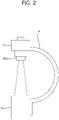
- FIG. 2 is an enlarged view of C-arm parts in FIG. 1 .
- the dose adjustment device according to the disclosure may be placed in a space between a radiation irradiator and a radiation detector of the diagnostic radiation apparatus.
- the dose adjustment device is provided at an end portion of the radiation irradiator, thereby easily adding a function of adjusting a radiation shielding rate for each portion without separate structural changes.
- FIG. 3 is a block diagram of a dose adjustment device according to an embodiment of the disclosure.
- the dose adjustment device may include a multi-leaf collimator module, a communication module, a power supply, and a controller.
- the multi-leaf collimator module may include a multi-leaf collimator, and an actuator.
- the multi-leaf collimator includes a plurality of single-leaves, so that the plurality of single-leaves can be combined to adjust the amount of radiation shielding for each portion.
- the multi-leaf collimator may be provided side by side on a plane perpendicular to an irradiating direction of the radiation.
- Each single-leaf 220 may extend a predetermined length in its lengthwise direction, and be in close contact with other single-leaves 220 in its widthwise direction.
- the single-leaves 220 may be arranged to have bilateral symmetry.
- the left single-leaves 220 and the right single-leaves 220 are provided to respectively adjust the shielded areas at both sides while bisecting a plurality of divided radiation irradiation areas.
- the radiation shielding rate of the single-leaf 220 may be varied depending on the material and thickness of the single-leaf 220. According to the features of the single-leaf 220, an image of a shielded area may be selected to be opaque or translucent. Meanwhile, detailed operations of such a collimator will be described later.
- a actuator 240 is configured to move the single-leaf 220 in the lengthwise direction.
- the actuator 240 may include actuation units 241 as many as the number of single-leaves 220 to move the single-leaves 220 independently of each other.
- Each actuation unit 241 is connected to one side of the single-leaf 220 and has an actuation amount based on a signal of a controller 300 (to be described later).
- a communication module 400 is configured to communicate with an external device.
- the communication module 400 receives a signal, which is input by a user for the positioin of the collimator 300, and transmits the received signal to the collimator 300.
- a power supply 500 may be configured to supply power to electric elements including the actuator 240, the communication module 400 and the controller 300.
- the power supply 500 may include a secondary battery so that charged energy can be used even when power is not separately supplied.
- the controller 300 may be configured to control the communication module 400 and the actuator 240.
- the controller 300 identifies an actuation amount based on the input and ultimately changes a position combination of the multi-leaf collimator.
- a dose adjustment device 1000 according to the disclosure will be described in detail with reference to FIGS. 4 and 5B .
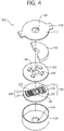
- FIG. 4 is an exploded perspective view of the dose adjustment device 1000 according to the disclosure.
- the dose adjustment device 1000 may be provided as a single body and mounted to a diagnostic radiation apparatus 10.
- the dose adjustment device 1000 may be shaped like a cylinder having a low height, and formed with a hole 140 in a center portion thereof to pass radiation therethrough.
- the dose adjustment device 1000 may include a multi-leaf collimator module 200, a controller 300, the communication module 400, and the power supply 500, which are placed inside a housing 100.
- the housing 100 may include an upper cap 110, a lower cap 120, and a connector 130.
- the upper cap 110 may be provided to include a top side of the housing 100
- the lower cap 120 may be provided to include a bottom side of the housing 100.
- the top and bottom sides are respectively formed with the holes 140 having a predetermined inner diameter to pass radiation therethrough.
- the upper cap 110 may be provided with the connectors 130 protruding at opposite sides so as to be easily connected to a radiation irradiator 11.
- the structure of the housing 100 is described by taking the shape shown in FIG. 4 as an example, but the housing may have various structures as long as it can place the multi-leaf collimator, the actuator 240 and the controller 300 therein. Further, the connector 130 may also have various structures for the connection with the end portion of the radiation irradiator 11.
- the battery, the controller 300, and the multi-leaf collimator module 200 may be stacked inside the housing 100. It is possible to maintain the easiness of mounting the dose adjustment device 1000 to the end portion of the radiation irradiator 11 and the easiness of controlling the diagnostic radiation apparatus 10 after the mounting.
- the battery may be shaped like a disk to enhance a spatial efficiency when being loaded into the housing 100.
- the battery may be shaped to form a part of the disk so that a structure for connection with an external power source can be disposed on the same layer.
- the controller 300 and the communication module 400 may be provided on a substrate.
- the substrate may also be shaped like a disk formed with the hole 140 in a center portion thereof to pass the radiation therethrough.
- the multi-leaf collimator module 200 may include a base 210 shaped like a disk formed with the hollow 140 in a center portion thereof, and include the multi-leaf collimator, a shaft 230 and the actuator 240 which are disposed on the base 210.
- the base 210 may have a symmetric axis as a central axis bisecting the plane thereof, and the multi-leaf collimator and the actuator 240 may be arranged to have bilateral symmetry.
- the outer diameter of the base 210 may be set to allow the single-leaf 220 to reciprocate between a state where the hollow 140 is fully closed and a state where the hollow 140 is fully opened.
- the base 210 may include a linear guide (not shown) to guide the moving direction of the single-leaf 220 so that the single-leaf 220 can reciprocate along a given path.
- the actuator 240 may include a plurality of actuation units 241 to respectively move the single-leaves 220 as described above.
- the plurality of actuation units 241 may be arranged in parallel with the lengthwise direction of the single-leaves 220, and disposed outward on the plane of the base 210.
- the shaft 230 may be provided in plural to connect each actuation unit 241 and one side of each single-leaf 220.
- this structure of the shaft 230 is merely an example, and the shaft 230 may have various connection structures as long as the actuation unit 241 can move the single-leaf 220.
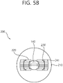
- FIGS. 5A and 5B are enlarged plan views of the multi-leaf collimator module 200.
- the multi-leaf collimator module 200 fully closes the center portion of the radiation irradiation area. As shown therein, the plurality of single-leaves 220 are dedicated to selectively close divisional portions of the radiation irradiation area.
- the center portion of the radiation irradiation area is partially opened. As shown therein, the left three single-leaves 220 and the right three single-leaves 220 are moved to their opened positions, thereby forming an opened area only in the center portion.
- FIGS. 6A and 7B illustrate use of the dose adjustment system according to a second embodiment of the disclosure.
- the dose adjustment system may include the dose adjustment device 1000 mountable to the diagnostic radiation apparatus 10, and a control device 600.
- the control device 600 may be configured to receive an adjustment amount for the dose adjustment device 1000 from a user, and generate an adjustment signal for adjusting the dose adjustment device 1000.
- the control device 600 may include a display 610, the touch panel and the communication module 400.
- the control device 600 is configured to receive and display a diagnostic image obtained by a diagnostic radiation irradiation apparatus. Further, the control device 600 is configured to display the adjustment amount for the dose adjustment device 1000 together with the diagnostic image.
- the control device 600 is configured to display a boundary line L between the opened area and the shielded area caused by the multi-leaf collimator module 200 on the display 610.
- the boundary line L may be provided as a line connecting the centers on the sides of the single-leaves 220 facing the symmetric axis.
- the diagnostic image displayed on the display 610 is obtained in an actually shielded state, and it is thus possible to obtain an image of the shielded portions with the naked eyes.
- the boundary line L displayed between the shielded area and the opened area makes it easier to recognize the images.
- FIG. 6A shows a diagnostic image obtained corresponding to an affected area
- FIG. 6B shows a position combination of the multi-leaf collimator in the dose adjustment device 1000 corresponding to FIG. 6A .
- a shading difference between the shielded area and the opened area is made with respect to the boundary line L, and an area except a portion of which an image is needed to be obtained, for example, a portion including blood vessels is shielded from the radiation.
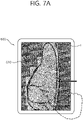
- a user can touch and drag the screen of the control device 600 to move the boundary line L.
- the control device 600 receives an input for controlling the boundary line L and communicates with the dose adjustment device 1000, thereby selecting the single-leaves 220 to be adjusted, setting a moving amount of the selected single-leaves 220, and controlling the actuation unit 241.
- the shielded area is adjusted by a user's input shown in FIG. 7A in real time when the diagnostic image is obtained using the radiation.
- FIGS. 8A and 8B show images for comparison between before and after using the dose adjustment device 1000 according to another embodiment of the disclosure.
- FIG. 8A shows a conventional method.
- the radiation shielding rate of the multi-leaf collimator module 200 is not 100% unlike that of the conventional method. Therefore, a certain amount of radiation may pass through the multi-leaf collimator even though the radiation irradiation area is shielded by the multi-leaf collimator module 200. Eventually, it is possible to obtain a translucent image, which is visible to the naked eyes, in a radiation diagnostic image.
- the material or thickness of the single-leaf 220 may be provided to pass a certain amount of radiation.
- the transmittance of an X-ray the multi-leaf collimator module 200 has may be within a range of 1% to 99%.
- FIGS. 9A and 9B show images for comparison between before and after using the dose adjustment device according to still another embodiment of the disclosure.
- this embodiment shows an example that the multi-leaf collimator module 200 fully shields the diagnostic radiation.
- FIG. 9A shows that the multi-leaf collimator is not used in a conventional art.
- FIG. 9B when the multi-leaf collimator is used according to the disclosure, an image of only an area opened through the multi-leaf collimator is obtained in an obtained diagnostic image, and a shielded area selected by a user is set and shielded from the radiation. According to this embodiment, the exposure to the radiation is fundamentally prevented in an area outside the area of interest.
- FIG. 10 is a conceptual view illustrating the stationary diagnostic radiation apparatus 10 with a dose adjustment system according to the disclosure.
- the stationary diagnostic radiation apparatus 10 includes a C-arm 14 hanging from the ceiling and guided by a plurality of linear guides to move on a plane in a diagnosis room.
- the C-arm 14 is provided to move on the plane and obtain a radiation diagnostic image of a patient lying on a patient supporter 15.
- the display 610 and a control panel 13 may be connected to the ceiling and disposed so that a user can use the diagnostic radiation apparatus 10.
- the dose adjustment device 1000 may be mounted to the end portion of the radiation irradiator 11 of the C-arm 14 like that of the foregoing embodiment. Meanwhile, the diagnostic radiation apparatus 10 may be used instead of the control device 600. In this case, the dose adjustment device 1000 may be controlled through the control panel 13 of the diagnostic radiation apparatus 10 without separately using the control device 600.
- the dose adjustment device can adjust the shielding rate for each portion based on a user's input in real time when a diagnostic image is obtained. Further, the dose adjustment device provided as a single body is mounted to the diagnostic radiation apparatus and adjusts the dose, thereby having an effect on adding a function without changing the design of a conventional diagnostic radiation apparatus.
Landscapes
- Health & Medical Sciences (AREA)
- Life Sciences & Earth Sciences (AREA)
- Engineering & Computer Science (AREA)
- Medical Informatics (AREA)
- Radiology & Medical Imaging (AREA)
- Molecular Biology (AREA)
- Biophysics (AREA)
- Nuclear Medicine, Radiotherapy & Molecular Imaging (AREA)
- Optics & Photonics (AREA)
- Pathology (AREA)
- Physics & Mathematics (AREA)
- Biomedical Technology (AREA)
- Heart & Thoracic Surgery (AREA)
- High Energy & Nuclear Physics (AREA)
- Surgery (AREA)
- Animal Behavior & Ethology (AREA)
- General Health & Medical Sciences (AREA)
- Public Health (AREA)
- Veterinary Medicine (AREA)
- Human Computer Interaction (AREA)
- Computer Networks & Wireless Communication (AREA)
- Apparatus For Radiation Diagnosis (AREA)
Applications Claiming Priority (2)
| Application Number | Priority Date | Filing Date | Title |
|---|---|---|---|
| KR1020190101964A KR102314902B1 (ko) | 2019-08-20 | 2019-08-20 | 진단용 방사선 장치에 장착 가능한 선량 조절 장치 및 이를 포함하는 선량 조절 시스템 |
| PCT/KR2020/007800 WO2021033900A1 (ko) | 2019-08-20 | 2020-06-17 | 진단용 방사선 장치에 장착 가능한 선량 조절 장치 및 이를 포함하는 선량 조절 시스템 |
Publications (4)
| Publication Number | Publication Date |
|---|---|
| EP4018933A1 true EP4018933A1 (de) | 2022-06-29 |
| EP4018933A4 EP4018933A4 (de) | 2023-08-23 |
| EP4018933B1 EP4018933B1 (de) | 2025-07-02 |
| EP4018933C0 EP4018933C0 (de) | 2025-07-02 |
Family
ID=74660284
Family Applications (1)
| Application Number | Title | Priority Date | Filing Date |
|---|---|---|---|
| EP20854895.8A Active EP4018933B1 (de) | 2019-08-20 | 2020-06-17 | Ein einem diagnostischen strahlungsgerät montierbare dosiseinstellvorrichtung und dosiseinstellsystem damit |
Country Status (5)
| Country | Link |
|---|---|
| US (1) | US11969285B2 (de) |
| EP (1) | EP4018933B1 (de) |
| JP (2) | JP2022544841A (de) |
| KR (1) | KR102314902B1 (de) |
| WO (1) | WO2021033900A1 (de) |
Families Citing this family (2)
| Publication number | Priority date | Publication date | Assignee | Title |
|---|---|---|---|---|
| US12042310B2 (en) * | 2021-04-02 | 2024-07-23 | Aixscan Inc. | X-ray multi-leaf dynamic collimation for multiple source-in-motion tomosynthesis imaging system |
| KR20250167329A (ko) | 2024-05-22 | 2025-12-01 | 원광보건대학교 산학협력단 | 의료용 투시장치의 인공물 삽입 판단 시스템 |
Family Cites Families (19)
| Publication number | Priority date | Publication date | Assignee | Title |
|---|---|---|---|---|
| JPS63216545A (ja) * | 1987-03-05 | 1988-09-08 | 株式会社 日立メデイコ | X線照射野調整装置 |
| GB2211709B (en) * | 1987-10-28 | 1991-03-20 | Philips Electronic Associated | Multileaf collimator and related apparatus |
| DE69605730T2 (de) | 1995-02-27 | 2000-07-20 | Koninklijke Philips Electronics N.V., Eindhoven | Eine kollimatoreinheit enthaltende röntgenstrahluntersuchungsvorrichtung |
| US7041941B2 (en) * | 1997-04-07 | 2006-05-09 | Patented Medical Solutions, Llc | Medical item thermal treatment systems and method of monitoring medical items for compliance with prescribed requirements |
| US6813337B2 (en) * | 2001-07-20 | 2004-11-02 | Siemens Medical Solutions Usa, Inc | Removable electron multileaf collimator |
| JP2003225235A (ja) * | 2002-02-05 | 2003-08-12 | Toshiba Corp | 絞りアライメント調整支援機能を持つx線診断装置及びその調整支援方法 |
| JP4256127B2 (ja) * | 2002-08-14 | 2009-04-22 | 株式会社東芝 | 集中照射型放射線治療装置 |
| US7539284B2 (en) | 2005-02-11 | 2009-05-26 | Besson Guy M | Method and system for dynamic low dose X-ray imaging |
| KR20130104965A (ko) * | 2012-03-16 | 2013-09-25 | 삼성디스플레이 주식회사 | 엑스선 검출장치 및 이를 이용하는 엑스선 촬영장치 |
| CN106030264B (zh) | 2013-12-11 | 2021-01-15 | 控制辐射系统有限公司 | X射线减少系统 |
| KR20160090060A (ko) * | 2015-01-21 | 2016-07-29 | 삼성전자주식회사 | 엑스선 영상 장치 및 그 제어방법 |
| KR101674529B1 (ko) * | 2015-09-09 | 2016-11-09 | 한국원자력의학원 | 다엽 콜리메이터 제어 장치 및 방법 |
| US10398911B2 (en) * | 2015-09-25 | 2019-09-03 | Varian Medical Systems Internationl AG | Method and apparatus for using a multi-layer multi-leaf collimation system |
| KR101743469B1 (ko) * | 2015-11-12 | 2017-06-05 | 대구보건대학교산학협력단 | 엑스선 검사장치 및 방법 |
| CN105326519B (zh) * | 2015-11-26 | 2017-03-22 | 上海联影医疗科技有限公司 | X射线图像形成、散射成分计算以及重建的方法及装置 |
| RU2019121943A (ru) | 2016-12-13 | 2021-01-15 | Вьюрэй Текнолоджиз, Инк. | Системы и способы лучевой терапии |
| WO2018147541A1 (ko) * | 2017-02-07 | 2018-08-16 | 한국원자력의학원 | 진단 방사선 기기용 가변형 콜리메이터 모듈 및 이를 이용한 시스템 |
| JP7080633B2 (ja) * | 2017-12-26 | 2022-06-06 | キヤノンメディカルシステムズ株式会社 | X線診断装置 |
| US10500417B2 (en) * | 2018-02-05 | 2019-12-10 | Varian Medical Systems International Ag | Compensating for leakage radiation in MLC modulated treatment |
-
2019
- 2019-08-20 KR KR1020190101964A patent/KR102314902B1/ko active Active
-
2020
- 2020-06-17 WO PCT/KR2020/007800 patent/WO2021033900A1/ko not_active Ceased
- 2020-06-17 US US17/636,778 patent/US11969285B2/en active Active
- 2020-06-17 EP EP20854895.8A patent/EP4018933B1/de active Active
- 2020-06-17 JP JP2022511308A patent/JP2022544841A/ja active Pending
-
2023
- 2023-05-31 JP JP2023090017A patent/JP7461537B2/ja active Active
Also Published As
| Publication number | Publication date |
|---|---|
| EP4018933B1 (de) | 2025-07-02 |
| JP2023116561A (ja) | 2023-08-22 |
| JP2022544841A (ja) | 2022-10-21 |
| US11969285B2 (en) | 2024-04-30 |
| US20220296198A1 (en) | 2022-09-22 |
| EP4018933A4 (de) | 2023-08-23 |
| WO2021033900A1 (ko) | 2021-02-25 |
| KR20210022445A (ko) | 2021-03-03 |
| EP4018933C0 (de) | 2025-07-02 |
| JP7461537B2 (ja) | 2024-04-03 |
| KR102314902B1 (ko) | 2021-10-21 |
Similar Documents
| Publication | Publication Date | Title |
|---|---|---|
| US7826593B2 (en) | Collimator | |
| EP2359905B1 (de) | Strahlentherapie und Abbildungsvorrichtung | |
| EP2020006B1 (de) | System zur Formung eines hochauflösenden Strahlungsfeldes | |
| JP7461537B2 (ja) | 診断用放射線装置に装着可能な線量調節装置、及びこれを含む線量調節システム | |
| EP2783633B1 (de) | System und Verfahren zur Strahlungssteuerung und -minimierung | |
| Takayama et al. | Initial validations for pursuing irradiation using a gimbals tracking system | |
| CN109432613B (zh) | 多源聚焦治疗和适形调强治疗放疗设备及其准直器组合 | |
| JP2008531172A (ja) | 放射線ビームを変調する方法および装置 | |
| JP2002224230A (ja) | マルチリーフコリメータ | |
| EP1946795A1 (de) | Strahlungs-/Bestrahlungsverfahren und Kontrollgerät für eine Radiotherapievorrichtung | |
| JP2010537784A (ja) | 患者支持デバイス | |
| WO2011009616A1 (en) | Linear kinematics system with rotatable treatment head | |
| WO2011108853A2 (ko) | 방사선 치료용 다엽 콜리메이터 장치 | |
| WO2015012505A1 (ko) | 유동픽셀 양성자 치료용 콜리메이터 | |
| US7489764B2 (en) | Adjustable aperture collimator | |
| US11559262B2 (en) | Operation and control of magnetic resonance imaging apparatus | |
| CN114796889A (zh) | 一种基于四维自适应数字跟踪适形调强聚焦医用电子加速器的精准放射治疗系统 | |
| GB2431554A (en) | Stand For An Irradiation Therapy Unit | |
| CN109011210A (zh) | 一种基于四维单源γ刀的放射治疗系统 | |
| JP4436343B2 (ja) | マルチリーフコリメータおよび放射線治療装置組立方法 | |
| US20110201918A1 (en) | Radiotherapy and imaging apparatus | |
| CN207614190U (zh) | 一种放射治疗用的辅助装置 | |
| WO2018147541A1 (ko) | 진단 방사선 기기용 가변형 콜리메이터 모듈 및 이를 이용한 시스템 | |
| CN109011209B (zh) | 一种基于四维单源γ刀的智能投照系统 | |
| Goetsch | Historic development of |
Legal Events
| Date | Code | Title | Description |
|---|---|---|---|
| STAA | Information on the status of an ep patent application or granted ep patent |
Free format text: STATUS: THE INTERNATIONAL PUBLICATION HAS BEEN MADE |
|
| PUAI | Public reference made under article 153(3) epc to a published international application that has entered the european phase |
Free format text: ORIGINAL CODE: 0009012 |
|
| STAA | Information on the status of an ep patent application or granted ep patent |
Free format text: STATUS: REQUEST FOR EXAMINATION WAS MADE |
|
| 17P | Request for examination filed |
Effective date: 20220221 |
|
| AK | Designated contracting states |
Kind code of ref document: A1 Designated state(s): AL AT BE BG CH CY CZ DE DK EE ES FI FR GB GR HR HU IE IS IT LI LT LU LV MC MK MT NL NO PL PT RO RS SE SI SK SM TR |
|
| DAV | Request for validation of the european patent (deleted) | ||
| DAX | Request for extension of the european patent (deleted) | ||
| A4 | Supplementary search report drawn up and despatched |
Effective date: 20230720 |
|
| RIC1 | Information provided on ipc code assigned before grant |
Ipc: G21K 1/04 20060101ALI20230714BHEP Ipc: A61B 6/06 20060101ALI20230714BHEP Ipc: A61B 6/00 20060101AFI20230714BHEP |
|
| GRAP | Despatch of communication of intention to grant a patent |
Free format text: ORIGINAL CODE: EPIDOSNIGR1 |
|
| STAA | Information on the status of an ep patent application or granted ep patent |
Free format text: STATUS: GRANT OF PATENT IS INTENDED |
|
| RIC1 | Information provided on ipc code assigned before grant |
Ipc: G21K 1/04 20060101ALI20250220BHEP Ipc: A61B 6/06 20060101ALI20250220BHEP Ipc: A61B 6/00 20060101AFI20250220BHEP |
|
| INTG | Intention to grant announced |
Effective date: 20250303 |
|
| GRAS | Grant fee paid |
Free format text: ORIGINAL CODE: EPIDOSNIGR3 |
|
| GRAA | (expected) grant |
Free format text: ORIGINAL CODE: 0009210 |
|
| STAA | Information on the status of an ep patent application or granted ep patent |
Free format text: STATUS: THE PATENT HAS BEEN GRANTED |
|
| AK | Designated contracting states |
Kind code of ref document: B1 Designated state(s): AL AT BE BG CH CY CZ DE DK EE ES FI FR GB GR HR HU IE IS IT LI LT LU LV MC MK MT NL NO PL PT RO RS SE SI SK SM TR |
|
| REG | Reference to a national code |
Ref country code: GB Ref legal event code: FG4D |
|
| REG | Reference to a national code |
Ref country code: CH Ref legal event code: EP |
|
| REG | Reference to a national code |
Ref country code: DE Ref legal event code: R096 Ref document number: 602020053966 Country of ref document: DE |
|
| REG | Reference to a national code |
Ref country code: IE Ref legal event code: FG4D |
|
| U01 | Request for unitary effect filed |
Effective date: 20250722 |
|
| U07 | Unitary effect registered |
Designated state(s): AT BE BG DE DK EE FI FR IT LT LU LV MT NL PT RO SE SI Effective date: 20250728 |
|
| PG25 | Lapsed in a contracting state [announced via postgrant information from national office to epo] |
Ref country code: IS Free format text: LAPSE BECAUSE OF FAILURE TO SUBMIT A TRANSLATION OF THE DESCRIPTION OR TO PAY THE FEE WITHIN THE PRESCRIBED TIME-LIMIT Effective date: 20251102 |
|
| PG25 | Lapsed in a contracting state [announced via postgrant information from national office to epo] |
Ref country code: NO Free format text: LAPSE BECAUSE OF FAILURE TO SUBMIT A TRANSLATION OF THE DESCRIPTION OR TO PAY THE FEE WITHIN THE PRESCRIBED TIME-LIMIT Effective date: 20251002 |
|
| PG25 | Lapsed in a contracting state [announced via postgrant information from national office to epo] |
Ref country code: HR Free format text: LAPSE BECAUSE OF FAILURE TO SUBMIT A TRANSLATION OF THE DESCRIPTION OR TO PAY THE FEE WITHIN THE PRESCRIBED TIME-LIMIT Effective date: 20250702 |
|
| PG25 | Lapsed in a contracting state [announced via postgrant information from national office to epo] |
Ref country code: GR Free format text: LAPSE BECAUSE OF FAILURE TO SUBMIT A TRANSLATION OF THE DESCRIPTION OR TO PAY THE FEE WITHIN THE PRESCRIBED TIME-LIMIT Effective date: 20251003 |
|
| PG25 | Lapsed in a contracting state [announced via postgrant information from national office to epo] |
Ref country code: CZ Free format text: LAPSE BECAUSE OF FAILURE TO SUBMIT A TRANSLATION OF THE DESCRIPTION OR TO PAY THE FEE WITHIN THE PRESCRIBED TIME-LIMIT Effective date: 20250702 |
|
| PG25 | Lapsed in a contracting state [announced via postgrant information from national office to epo] |
Ref country code: PL Free format text: LAPSE BECAUSE OF FAILURE TO SUBMIT A TRANSLATION OF THE DESCRIPTION OR TO PAY THE FEE WITHIN THE PRESCRIBED TIME-LIMIT Effective date: 20250702 |
|
| PG25 | Lapsed in a contracting state [announced via postgrant information from national office to epo] |
Ref country code: RS Free format text: LAPSE BECAUSE OF FAILURE TO SUBMIT A TRANSLATION OF THE DESCRIPTION OR TO PAY THE FEE WITHIN THE PRESCRIBED TIME-LIMIT Effective date: 20251002 |
|
| PG25 | Lapsed in a contracting state [announced via postgrant information from national office to epo] |
Ref country code: ES Free format text: LAPSE BECAUSE OF FAILURE TO SUBMIT A TRANSLATION OF THE DESCRIPTION OR TO PAY THE FEE WITHIN THE PRESCRIBED TIME-LIMIT Effective date: 20250702 |
|
| PG25 | Lapsed in a contracting state [announced via postgrant information from national office to epo] |
Ref country code: SM Free format text: LAPSE BECAUSE OF FAILURE TO SUBMIT A TRANSLATION OF THE DESCRIPTION OR TO PAY THE FEE WITHIN THE PRESCRIBED TIME-LIMIT Effective date: 20250702 |
|
| PG25 | Lapsed in a contracting state [announced via postgrant information from national office to epo] |
Ref country code: SK Free format text: LAPSE BECAUSE OF FAILURE TO SUBMIT A TRANSLATION OF THE DESCRIPTION OR TO PAY THE FEE WITHIN THE PRESCRIBED TIME-LIMIT Effective date: 20250702 |
|
| PLBE | No opposition filed within time limit |
Free format text: ORIGINAL CODE: 0009261 |
|
| STAA | Information on the status of an ep patent application or granted ep patent |
Free format text: STATUS: NO OPPOSITION FILED WITHIN TIME LIMIT |