EP4018653B1 - Geometrischer partitionsmodus mit harmonischer bewegungsfeldspeicherung und bewegungskompensation - Google Patents
Geometrischer partitionsmodus mit harmonischer bewegungsfeldspeicherung und bewegungskompensation Download PDFInfo
- Publication number
- EP4018653B1 EP4018653B1 EP20768168.5A EP20768168A EP4018653B1 EP 4018653 B1 EP4018653 B1 EP 4018653B1 EP 20768168 A EP20768168 A EP 20768168A EP 4018653 B1 EP4018653 B1 EP 4018653B1
- Authority
- EP
- European Patent Office
- Prior art keywords
- block
- video
- partition
- current block
- prediction
- Prior art date
- Legal status (The legal status is an assumption and is not a legal conclusion. Google has not performed a legal analysis and makes no representation as to the accuracy of the status listed.)
- Active
Links
Images


Classifications
-
- H—ELECTRICITY
- H04—ELECTRIC COMMUNICATION TECHNIQUE
- H04N—PICTORIAL COMMUNICATION, e.g. TELEVISION
- H04N19/00—Methods or arrangements for coding, decoding, compressing or decompressing digital video signals
- H04N19/10—Methods or arrangements for coding, decoding, compressing or decompressing digital video signals using adaptive coding
- H04N19/102—Methods or arrangements for coding, decoding, compressing or decompressing digital video signals using adaptive coding characterised by the element, parameter or selection affected or controlled by the adaptive coding
- H04N19/119—Adaptive subdivision aspects, e.g. subdivision of a picture into rectangular or non-rectangular coding blocks
-
- H—ELECTRICITY
- H04—ELECTRIC COMMUNICATION TECHNIQUE
- H04N—PICTORIAL COMMUNICATION, e.g. TELEVISION
- H04N19/00—Methods or arrangements for coding, decoding, compressing or decompressing digital video signals
- H04N19/10—Methods or arrangements for coding, decoding, compressing or decompressing digital video signals using adaptive coding
- H04N19/102—Methods or arrangements for coding, decoding, compressing or decompressing digital video signals using adaptive coding characterised by the element, parameter or selection affected or controlled by the adaptive coding
- H04N19/103—Selection of coding mode or of prediction mode
- H04N19/105—Selection of the reference unit for prediction within a chosen coding or prediction mode, e.g. adaptive choice of position and number of pixels used for prediction
-
- H—ELECTRICITY
- H04—ELECTRIC COMMUNICATION TECHNIQUE
- H04N—PICTORIAL COMMUNICATION, e.g. TELEVISION
- H04N19/00—Methods or arrangements for coding, decoding, compressing or decompressing digital video signals
- H04N19/10—Methods or arrangements for coding, decoding, compressing or decompressing digital video signals using adaptive coding
- H04N19/102—Methods or arrangements for coding, decoding, compressing or decompressing digital video signals using adaptive coding characterised by the element, parameter or selection affected or controlled by the adaptive coding
- H04N19/132—Sampling, masking or truncation of coding units, e.g. adaptive resampling, frame skipping, frame interpolation or high-frequency transform coefficient masking
-
- H—ELECTRICITY
- H04—ELECTRIC COMMUNICATION TECHNIQUE
- H04N—PICTORIAL COMMUNICATION, e.g. TELEVISION
- H04N19/00—Methods or arrangements for coding, decoding, compressing or decompressing digital video signals
- H04N19/10—Methods or arrangements for coding, decoding, compressing or decompressing digital video signals using adaptive coding
- H04N19/134—Methods or arrangements for coding, decoding, compressing or decompressing digital video signals using adaptive coding characterised by the element, parameter or criterion affecting or controlling the adaptive coding
- H04N19/154—Measured or subjectively estimated visual quality after decoding, e.g. measurement of distortion
-
- H—ELECTRICITY
- H04—ELECTRIC COMMUNICATION TECHNIQUE
- H04N—PICTORIAL COMMUNICATION, e.g. TELEVISION
- H04N19/00—Methods or arrangements for coding, decoding, compressing or decompressing digital video signals
- H04N19/10—Methods or arrangements for coding, decoding, compressing or decompressing digital video signals using adaptive coding
- H04N19/169—Methods or arrangements for coding, decoding, compressing or decompressing digital video signals using adaptive coding characterised by the coding unit, i.e. the structural portion or semantic portion of the video signal being the object or the subject of the adaptive coding
- H04N19/17—Methods or arrangements for coding, decoding, compressing or decompressing digital video signals using adaptive coding characterised by the coding unit, i.e. the structural portion or semantic portion of the video signal being the object or the subject of the adaptive coding the unit being an image region, e.g. an object
- H04N19/176—Methods or arrangements for coding, decoding, compressing or decompressing digital video signals using adaptive coding characterised by the coding unit, i.e. the structural portion or semantic portion of the video signal being the object or the subject of the adaptive coding the unit being an image region, e.g. an object the region being a block, e.g. a macroblock
-
- H—ELECTRICITY
- H04—ELECTRIC COMMUNICATION TECHNIQUE
- H04N—PICTORIAL COMMUNICATION, e.g. TELEVISION
- H04N19/00—Methods or arrangements for coding, decoding, compressing or decompressing digital video signals
- H04N19/50—Methods or arrangements for coding, decoding, compressing or decompressing digital video signals using predictive coding
- H04N19/503—Methods or arrangements for coding, decoding, compressing or decompressing digital video signals using predictive coding involving temporal prediction
- H04N19/51—Motion estimation or motion compensation
- H04N19/537—Motion estimation other than block-based
-
- H—ELECTRICITY
- H04—ELECTRIC COMMUNICATION TECHNIQUE
- H04N—PICTORIAL COMMUNICATION, e.g. TELEVISION
- H04N19/00—Methods or arrangements for coding, decoding, compressing or decompressing digital video signals
- H04N19/50—Methods or arrangements for coding, decoding, compressing or decompressing digital video signals using predictive coding
- H04N19/503—Methods or arrangements for coding, decoding, compressing or decompressing digital video signals using predictive coding involving temporal prediction
- H04N19/51—Motion estimation or motion compensation
- H04N19/567—Motion estimation based on rate distortion criteria
-
- H—ELECTRICITY
- H04—ELECTRIC COMMUNICATION TECHNIQUE
- H04N—PICTORIAL COMMUNICATION, e.g. TELEVISION
- H04N19/00—Methods or arrangements for coding, decoding, compressing or decompressing digital video signals
- H04N19/70—Methods or arrangements for coding, decoding, compressing or decompressing digital video signals characterised by syntax aspects related to video coding, e.g. related to compression standards
Definitions
- This disclosure relates to video encoding and video decoding.
- Digital video capabilities can be incorporated into a wide range of devices, including digital televisions, digital direct broadcast systems, wireless broadcast systems, personal digital assistants (PDAs), laptop or desktop computers, tablet computers, e-book readers, digital cameras, digital recording devices, digital media players, video gaming devices, video game consoles, cellular or satellite radio telephones, so-called "smart phones," video teleconferencing devices, video streaming devices, and the like.
- Digital video devices implement video coding techniques, such as those described in the standards defined by MPEG-2, MPEG-4, ITU-T H.263, ITU-T H.264/MPEG-4, Part 10, Advanced Video Coding (AVC), ITU-T H.265/High Efficiency Video Coding (HEVC), and extensions of such standards.
- the video devices may transmit, receive, encode, decode, and/or store digital video information more efficiently by implementing such video coding techniques.
- Video coding techniques include spatial (intra-picture) prediction and/or temporal (inter-picture) prediction to reduce or remove redundancy inherent in video sequences.
- a video slice e.g., a video picture or a portion of a video picture
- video blocks which may also be referred to as coding tree units (CTUs), coding units (CUs) and/or coding nodes.
- Video blocks in an intra-coded (I) slice of a picture are encoded using spatial prediction with respect to reference samples in neighboring blocks in the same picture.
- Video blocks in an inter-coded (P or B) slice of a picture may use spatial prediction with respect to reference samples in neighboring blocks in the same picture or temporal prediction with respect to reference samples in other reference pictures.
- Pictures may be referred to as frames, and reference pictures may be referred to as reference frames.
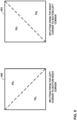
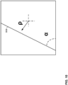
- Geometric partition mode may refer to a partition mode configured to support splitting a block of video data into one or more shapes such as, for example, a triangle shape, a trapezoid shape or a rectangular shape.
- a video coder e.g., a video encoder or a video decoder
- the video coder may split a block of video data along a diagonal or anti-diagonal split that evenly splits a block into a first triangle partition and a second triangle partition.
- techniques described herein configure a video coder to apply a geometric partition mode that selects an angle for the split line from angles corresponding to an N:M ratio of samples of a current block, wherein N and M are integers. Additionally, the split line may not be at a corner of a block. The angles corresponding to an N:M ratio may permit the video coder to apply a geometric partition mode that supports angles for various block ratios (e.g., 1:1, 1:2, 1:4, 0: 1, 2:1, and 1:0) that are computationally efficient.
- the video coder may apply a geometric partition mode that supports angles that may be implemented by the video coder using bit-shifting rather than multiplication functions, which may potentially improve a computational efficiency of the video coder with little or no impact on coding accuracy compared to video coders configured to apply a geometric partition mode using 32 angles of 11.25 degrees.
- this disclosure describes techniques for video coding. More specifically, the techniques of this disclosure are directed to partitioning for motion estimation, such as, for example, a triangular partition mode, a geometric partition mode (GPM), or another partition mode.
- a video coder e.g., a video encoder or a video decoder
- partitioning of video data frequently refers to a process where a video encoder divides a coding tree unit (CTU) along vertical or horizontal directions (see for example FIG. 2B ) and signals information including a residual block for each block of video data.
- CTU coding tree unit
- a video coder may apply a triangular partition mode to partition a rectangular block of video data into a first triangular partition and a second triangular partition.
- the video coder may apply a split line from a first corner of the rectangular block (e.g., an upper-left corner or a lower-left corner) to a second corner of the rectangular block (e.g., a lower-right corner or an upper-right corner).
- the video coder may generate samples for a first prediction block using motion information for the first triangular partition and generate a second prediction block using motion information for the second triangular partition.
- the video coder may blend (e.g., weighted average) samples from the first prediction block and the second prediction block along the split line dividing the first triangular partition and the second triangular partition to generate a final prediction block for the block of the video data.
- a video encoder does not signal first residual information for the first triangular partition and second residual information for the second triangular partition. Instead, the video encoder may signal a single residual block for the entire block of video data. In this way, samples arranged in a portion of video data with similar motion may be grouped together, which may potentially improve a coding accuracy with little or no impact on computational complexity.
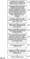
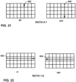
- a video coder when operating in triangle partition mode, may split a block of video data along a diagonal or anti-diagonal split that evenly splits a block into a first partition and a second partition, where the first partition comprises a same number of samples as the second partition. While triangle partition mode may partition a square block along a 45 degree angle, the video coder may apply different triangle partition mode angles to non-square rectangular blocks.
- the video coder may apply triangle partition mode to determine a first split line at a first triangle partition mode angle to evenly split a first block comprising a width:height ratio of 1:2, apply the triangle partition mode to determine a second split line at a second triangle partition mode angles to evenly split a second block comprising a width:height ratio of 1:4, and so on.
- the set of triangle partition mode angles may include diagonal angles to accommodate each possible block ratio, such as, for example, 1:1, 1:2, 1:4, and 2:1.
- the value for N or M of an N:M ratio of samples of a current block may be 2 ⁇ X, where X is 0 or positive integer.
- the set of triangle partition mode angles may include anti-diagonal angles to accommodate each possible block ratio, such as, for example, 1:1, 1:2, 1:4, 2:1.
- the set of triangle partition mode angles may include a corresponding +180 degree angle for each of the diagonal angles and each of the anti-diagonal angles.
- the triangle set partition mode angles may include 4 diagonal angles, 4 diagonal angles with a 180 degree offset, 4 anti-diagonal angles, and 4 anti-diagonal angles with the 180 degree offset for a total of 16 angles.
- the video coder may apply a geometric partition mode to split a block of video data into one or more triangular shapes and one or more a non-triangular shapes, such as, for example, a trapezoid shape or a rectangular shape.
- a video coder e.g., a video encoder or a video decoder
- the video coder may apply the geometric partition mode weights to samples of the first prediction block and to samples of the second prediction block to determine a final prediction block for the current block.
- a video coder may apply geometric partition mode to split a block of video data into a first partition and a second partition, where the first partition comprises more samples than the second partition.
- the video coder may allow for the video coder to include additional samples with similar motion within a single partition, which may potentially improve a coding accuracy with little or no impact on computational complexity compared to systems video coders that rely on equal sized partitions and/or rectangular and triangular partitioning.
- some video coders may be configured to use 32 angles of 11.25 degrees to select an angle of a split line.
- a video encoder may signal a value indicating a selection of one angle index from a set of 0-31.
- an angle index of 0 may represent 0 degrees
- an angle index of 1 may represent 11.25 degrees
- an angle index of 2 may represent 22.5 degrees, and so on.
- the video encoder may signal the value to indicate a line displacement relatively to a center of the block.
- a video decoder may receive the value indicating the selection of one angle index from a set of 0-31 and the line displacement to determine a split line for the block.
- the video coder may apply a geometric partition mode to split a block of video data unevenly and/or to allow a splitting of the block of video data into a non-rectangular and a non-triangular shape, which may potentially improve a coding accuracy with little or no impact on computational complexity compared to systems video coders that rely on equal sized partitions and/or rectangular and triangular partitioning.
- one or more problems may exist with configuring a video coder (e.g., a video encoder or a video decoder) to use 32 angles of 11.25 degrees to select an angle of a split line.
- the 32 angles of 11.25 degrees may result in the video coder using multiplication functions to multiply a sample position times a cosine of the angle, which may be computationally extensive causing delays in the coding.
- Techniques described herein may represent one or more solutions to the problems existing with using 32 angles of 11.25 degrees to select an angle of a split line.
- a set of angles for applicable to triangular partitioning may, instead, be applied to geometric partition mode such that the geometric partitioning mode may include a set of different angles.
- the set of angles used for geometric mode partitioning may include triangle set partition mode angles corresponding to an N:M ratio, where N and M are integers,
- the set of angles used for geometric mode partitioning may include triangle set partition mode angles corresponding to 1:1, 1:2, 1:4, and 2:1.
- the set of angles used for geometric mode partitioning may include a set of 4 diagonal angles, 4 diagonal angles with a 180 degree offset, 4 anti-diagonal angles, and 4 anti-diagonal angles with the 180 degree offset.
- the video coder may determine the set of angles used for geometric mode partitioning may further include angles to support a splitting of a block into a rectangular shape.
- the set of angles used for geometric mode partitioning may further include one or more horizontal angles and/or one or more vertical angles.
- GPM allows for a split line to be displaced from a corners of a current block.
- a video coder e.g., video encoder or video decoder
- the video coder may determine the split line is arranged such that one or more of the first partition or the second partition comprise a non-triangular shape (e.g., trapezoidal).
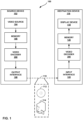
- FIG. 1 is a block diagram illustrating an example video encoding and decoding system 100 that may perform the techniques of this disclosure.
- the techniques of this disclosure are generally directed to coding (encoding and/or decoding) video data.
- video data includes any data for processing a video.
- video data may include raw, unencoded video, encoded video, decoded (e.g., reconstructed) video, and video metadata, such as signaling data.
- system 100 includes a source device 102 that provides encoded video data to be decoded and displayed by a destination device 116, in this example.
- source device 102 provides the video data to destination device 116 via a computer-readable medium 110.
- Source device 102 and destination device 116 may comprise any of a wide range of devices, including desktop computers, notebook (i.e., laptop) computers, tablet computers, set-top boxes, telephone handsets such smartphones, televisions, cameras, display devices, digital media players, video gaming consoles, video streaming device, or the like.
- source device 102 and destination device 116 may be equipped for wireless communication, and thus may be referred to as wireless communication devices.
- source device 102 includes video source 104, memory 106, video encoder 200, and output interface 108.
- video encoder 200 of source device 102 and video decoder 300 of destination device 116 may be configured to apply the techniques for Geometric Partition Mode with Harmonized Motion Field Storage and Motion Compensation.
- source device 102 represents an example of a video encoding device
- destination device 116 represents an example of a video decoding device.
- a source device and a destination device may include other components or arrangements.
- source device 102 may receive video data from an external video source, such as an external camera.
- destination device 116 may interface with an external display device, rather than including an integrated display device.
- video source 104 represents a source of video data (i.e., raw, unencoded video data) and provides a sequential series of pictures (also referred to as "frames") of the video data to video encoder 200, which encodes data for the pictures.
- Video source 104 of source device 102 may include a video capture device, such as a video camera, a video archive containing previously captured raw video, and/or a video feed interface to receive video from a video content provider.
- video source 104 may generate computer graphics-based data as the source video, or a combination of live video, archived video, and computer-generated video.
- video encoder 200 encodes the captured, pre-captured, or computer-generated video data.
- Memory 106 of source device 102 and memory 120 of destination device 116 represent general purpose memories.
- memories 106, 120 may store raw video data, e.g., raw video from video source 104 and raw, decoded video data from video decoder 300.
- memories 106, 120 may store software instructions executable by, e.g., video encoder 200 and video decoder 300, respectively.
- memory 106 and memory 120 are shown separately from video encoder 200 and video decoder 300 in this example, it should be understood that video encoder 200 and video decoder 300 may also include internal memories for functionally similar or equivalent purposes.
- memories 106, 120 may store encoded video data, e.g., output from video encoder 200 and input to video decoder 300.
- portions of memories 106, 120 may be allocated as one or more video buffers, e.g., to store raw, decoded, and/or encoded video data.
- Computer-readable medium 110 may represent any type of medium or device capable of transporting the encoded video data from source device 102 to destination device 116.
- computer-readable medium 110 represents a communication medium to enable source device 102 to transmit encoded video data directly to destination device 116 in real-time, e.g., via a radio frequency network or computer-based network.
- Output interface 108 may modulate a transmission signal including the encoded video data, and input interface 122 may demodulate the received transmission signal, according to a communication standard, such as a wireless communication protocol.
- the communication medium may comprise any wireless or wired communication medium, such as a radio frequency (RF) spectrum or one or more physical transmission lines.
- RF radio frequency
- the communication medium may form part of a packet-based network, such as a local area network, a wide-area network, or a global network such as the Internet.
- the communication medium may include routers, switches, base stations, or any other equipment that may be useful to facilitate communication from source device 102 to destination device 116.
- computer-readable medium 110 may include file server 114 or another intermediate storage device that may store the encoded video data generated by source device 102.
- Source device 102 may output encoded video data to file server 114 or another intermediate storage device that may store the encoded video generated by source device 102.
- Destination device 116 may access stored video data from file server 114 via streaming or download.
- File server 114 may be any type of server device capable of storing encoded video data and transmitting that encoded video data to the destination device 116.
- File server 114 may represent a web server (e.g., for a website), a File Transfer Protocol (FTP) server, a content delivery network device, or a network attached storage (NAS) device.
- FTP File Transfer Protocol
- NAS network attached storage
- Destination device 116 may access encoded video data from file server 114 through any standard data connection, including an Internet connection. This may include a wireless channel (e.g., a Wi-Fi connection), a wired connection (e.g., digital subscriber line (DSL), cable modem, etc.), or a combination of both that is suitable for accessing encoded video data stored on file server 114.
- File server 114 and input interface 122 may be configured to operate according to a streaming transmission protocol, a download transmission protocol, or a combination thereof.
- Output interface 108 and input interface 122 may represent wireless transmitters/receivers, modems, wired networking components (e.g., Ethernet cards), wireless communication components that operate according to any of a variety of IEEE 802.11 standards, or other physical components.
- output interface 108 and input interface 122 may be configured to transfer data, such as encoded video data, according to a cellular communication standard, such as 4G, 4G-LTE (Long-Term Evolution), LTE Advanced, 5G, or the like.
- output interface 108 comprises a wireless transmitter
- output interface 108 and input interface 122 may be configured to transfer data, such as encoded video data, according to other wireless standards, such as an IEEE 802.11 specification, an IEEE 802.15 specification (e.g., ZigBee TM ), a Bluetooth TM standard, or the like.
- source device 102 and/or destination device 116 may include respective system-on-a-chip (SoC) devices.
- SoC system-on-a-chip
- source device 102 may include an SoC device to perform the functionality attributed to video encoder 200 and/or output interface 108
- destination device 116 may include an SoC device to perform the functionality attributed to video decoder 300 and/or input interface 122.
- the techniques of this disclosure may be applied to video coding in support of any of a variety of multimedia applications, such as over-the-air television broadcasts, cable television transmissions, satellite television transmissions, Internet streaming video transmissions, such as dynamic adaptive streaming over HTTP (DASH), digital video that is encoded onto a data storage medium, decoding of digital video stored on a data storage medium, or other applications.
- multimedia applications such as over-the-air television broadcasts, cable television transmissions, satellite television transmissions, Internet streaming video transmissions, such as dynamic adaptive streaming over HTTP (DASH), digital video that is encoded onto a data storage medium, decoding of digital video stored on a data storage medium, or other applications.
- DASH dynamic adaptive streaming over HTTP
- Each of video encoder 200 and video decoder 300 may be included in one or more encoders or decoders, either of which may be integrated as part of a combined encoder/decoder (CODEC) in a respective device.
- a device including video encoder 200 and/or video decoder 300 may comprise an integrated circuit, a microprocessor, and/or a wireless communication device, such as a cellular telephone.
- Video encoder 200 and video decoder 300 may operate according to a video coding standard, such as ITU-T H.265, also referred to as High Efficiency Video Coding (HEVC) or extensions thereto, such as the multi-view and/or scalable video coding extensions.
- video encoder 200 and video decoder 300 may operate according to other proprietary or industry standards, such as ITU-T H.266, also referred to as Versatile Video Coding (VVC).
- VVC Versatile Video Coding
- video encoder 200 and video decoder 300 may perform block-based coding of pictures.
- the term "block” generally refers to a structure including data to be processed (e.g., encoded, decoded, or otherwise used in the encoding and/or decoding process).
- a block may include a two-dimensional matrix of samples of luminance and/or chrominance data.
- video encoder 200 and video decoder 300 may code video data represented in a YUV (e.g., Y, Cb, Cr) format.
- YUV e.g., Y, Cb, Cr
- video encoder 200 and video decoder 300 may code luminance and chrominance components, where the chrominance components may include both red hue and blue hue chrominance components.
- video encoder 200 converts received RGB formatted data to a YUV representation prior to encoding
- video decoder 300 converts the YUV representation to the RGB format.
- pre- and post-processing units may perform these conversions.
- This disclosure may generally refer to coding (e.g., encoding and decoding) of pictures to include the process of encoding or decoding data of the picture.
- this disclosure may refer to coding of blocks of a picture to include the process of encoding or decoding data for the blocks, e.g., prediction and/or residual coding.
- An encoded video bitstream generally includes a series of values for syntax elements representative of coding decisions (e.g., coding modes) and partitioning of pictures into blocks.
- references to coding a picture or a block should generally be understood as coding values for syntax elements forming the picture or block.
- HEVC defines various blocks, including coding units (CUs), prediction units (PUs), and transform units (TUs).
- a video coder such as video encoder 200 partitions a coding tree unit (CTU) into CUs according to a quadtree structure. That is, the video coder partitions CTUs and CUs into four equal, nonoverlapping squares, and each node of the quadtree has either zero or four child nodes. Nodes without child nodes may be referred to as "leaf nodes," and CUs of such leaf nodes may include one or more PUs and/or one or more TUs.
- the video coder may further partition PUs and TUs.
- a residual quadtree represents partitioning of TUs.
- PUs represent inter-prediction data
- TUs represent residual data.
- CUs that are intra-predicted include intra-prediction information, such as an intra-mode indication.
- video encoder 200 and video decoder 300 may be configured to operate according to VVC.
- a video coder such as video encoder 200 partitions a picture into a plurality of coding tree units (CTUs).
- Video encoder 200 may partition a CTU according to a tree structure, such as a quadtree-binary tree (QTBT) structure or Multi-Type Tree (MTT) structure.
- QTBT structure removes the concepts of multiple partition types, such as the separation between CUs, PUs, and TUs of HEVC.
- a QTBT structure includes two levels: a first level partitioned according to quadtree partitioning, and a second level partitioned according to binary tree partitioning.
- a root node of the QTBT structure corresponds to a CTU.
- Leaf nodes of the binary trees correspond to coding units (CUs).
- blocks may be partitioned using a quadtree (QT) partition, a binary tree (BT) partition, and one or more types of triple tree (TT) (also called ternary tree (TT)) partitions.
- QT quadtree
- BT binary tree
- TT triple tree
- a triple or ternary tree partition is a partition where a block is split into three sub-blocks.
- a triple or ternary tree partition divides a block into three sub-blocks without dividing the original block through the center.
- the partitioning types in MTT e.g., QT, BT, and TT), may be symmetrical or asymmetrical.
- video encoder 200 and video decoder 300 may use a single QTBT or MTT structure to represent each of the luminance and chrominance components, while in other examples, video encoder 200 and video decoder 300 may use two or more QTBT or MTT structures, such as one QTBT/MTT structure for the luminance component and another QTBT/MTT structure for both chrominance components (or two QTBT/MTT structures for respective chrominance components).
- Video encoder 200 and video decoder 300 may be configured to use quadtree partitioning per HEVC, QTBT partitioning, MTT partitioning, or other partitioning structures.
- quadtree partitioning per HEVC, QTBT partitioning, MTT partitioning, or other partitioning structures.
- the description of the techniques of this disclosure is presented with respect to QTBT partitioning.
- the techniques of this disclosure may also be applied to video coders configured to use quadtree partitioning, or other types of partitioning as well.
- the blocks may be grouped in various ways in a picture.
- a brick may refer to a rectangular region of CTU rows within a particular tile in a picture.
- a tile may be a rectangular region of CTUs within a particular tile column and a particular tile row in a picture.
- a tile column refers to a rectangular region of CTUs having a height equal to the height of the picture and a width specified by syntax elements (e.g., such as in a picture parameter set).
- a tile row refers to a rectangular region of CTUs having a height specified by syntax elements (e.g., such as in a picture parameter set) and a width equal to the width of the picture.
- a tile may be partitioned into multiple bricks, each of which may include one or more CTU rows within the tile.
- a tile that is not partitioned into multiple bricks may also be referred to as a brick.
- a brick that is a true subset of a tile may not be referred to as a tile.
- a slice may be an integer number of bricks of a picture that may be exclusively contained in a single network abstraction layer (NAL) unit.
- NAL network abstraction layer
- a slice includes either a number of complete tiles or only a consecutive sequence of complete bricks of one tile.
- NxN and N by N interchangeably to refer to the sample dimensions of a block (such as a CU or other video block) in terms of vertical and horizontal dimensions, e.g., 16x16 samples or 16 by 16 samples.
- an NxN CU generally has N samples in a vertical direction and N samples in a horizontal direction, where N represents a nonnegative integer value.
- the samples in a CU may be arranged in rows and columns.
- CUs need not necessarily have the same number of samples in the horizontal direction as in the vertical direction.
- CUs may comprise NxM samples, where M is not necessarily equal to N.
- Video encoder 200 encodes video data for CUs representing prediction and/or residual information, and other information.
- the prediction information indicates how the CU is to be predicted in order to form a prediction block for the CU.
- the residual information generally represents sample-by-sample differences between samples of the CU prior to encoding and the prediction block.
- video encoder 200 may generally form a prediction block for the CU through inter-prediction or intra-prediction.
- Inter-prediction generally refers to predicting the CU from data of a previously coded picture
- intra-prediction generally refers to predicting the CU from previously coded data of the same picture.
- video encoder 200 may generate the prediction block using one or more motion vectors.
- Video encoder 200 may generally perform a motion search to identify a reference block that closely matches the CU, e.g., in terms of differences between the CU and the reference block.
- Video encoder 200 may calculate a difference metric using a sum of absolute difference (SAD), sum of squared differences (SSD), mean absolute difference (MAD), mean squared differences (MSD), or other such difference calculations to determine whether a reference block closely matches the current CU.
- video encoder 200 may predict the current CU using uni-directional prediction or bi-directional prediction.
- VVC also provide an affine motion compensation mode, which may be considered an inter-prediction mode.
- affine motion compensation mode video encoder 200 may determine two or more motion vectors that represent non-translational motion, such as zoom in or out, rotation, perspective motion, or other irregular motion types.
- video encoder 200 may select an intra-prediction mode to generate the prediction block.
- VVC provides sixty-seven intra-prediction modes, including various directional modes, as well as planar mode and DC mode.
- video encoder 200 selects an intra-prediction mode that describes neighboring samples to a current block (e.g., a block of a CU) from which to predict samples of the current block. Such samples may generally be above, above and to the left, or to the left of the current block in the same picture as the current block, assuming video encoder 200 codes CTUs and CUs in raster scan order (left to right, top to bottom).
- Video encoder 200 may apply geometric partition mode to generate a first partition of the current block of video data and a second partition of the block of video data.
- video encoder 200 may select a split line comprising an angle and a displacement (e.g., a horizontal displacement from a center of the current block, a vertical displacement from the center of the current block, or a displacement from the center of the current block).
- the video encoder 200 may signal an indication (e.g., an index) of the split line.
- Video encoder 200 may generate a first prediction block using first motion information for the first partition and generate a second prediction block using second motion information for the second partition. Video encoder 200 may determine geometric mode weights to apply to the first and second prediction blocks using the angle of the split line. For example, video encoder 200 may apply a weight map that applies a weight to values of the current block consistent with the weights illustrated in the example of FIG. 8 relative to the split line. Video encoder 200 may determine a final prediction block using the geometric partition mode weights. For example, video encoder 200 may apply a respective geometric partition mode weight to each co-located sample of the first prediction block and the second prediction block to determine a value for a sample of the final prediction block.
- Video encoder 200 encodes data representing the prediction mode for a current block. For example, for inter-prediction modes, video encoder 200 may encode data representing which of the various available inter-prediction modes is used, as well as motion information for the corresponding mode. For uni-directional or bi-directional inter-prediction, for example, video encoder 200 may encode motion vectors using advanced motion vector prediction (AMVP) or merge mode. Video encoder 200 may use similar modes to encode motion vectors for affine motion compensation mode.
- AMVP advanced motion vector prediction
- Video encoder 200 may use similar modes to encode motion vectors for affine motion compensation mode.
- video encoder 200 may calculate residual data for the block.
- the residual data such as a residual block, represents sample by sample differences between the block and a prediction block for the block, formed using the corresponding prediction mode.
- Video encoder 200 may apply one or more transforms to the residual block, to produce transformed data in a transform domain instead of the sample domain.
- video encoder 200 may apply a discrete cosine transform (DCT), an integer transform, a wavelet transform, or a conceptually similar transform to residual video data.
- DCT discrete cosine transform
- an integer transform an integer transform
- wavelet transform or a conceptually similar transform
- video encoder 200 may apply a secondary transform following the first transform, such as a mode-dependent non-separable secondary transform (MDNSST), a signal dependent transform, a Karhunen-Loeve transform (KLT), or the like.
- Video encoder 200 produces transform coefficients following application of the one or more transforms.
- video encoder 200 may perform quantization of the transform coefficients.
- Quantization generally refers to a process in which transform coefficients are quantized to possibly reduce the amount of data used to represent the transform coefficients, providing further compression.
- video encoder 200 may reduce the bit depth associated with some or all of the transform coefficients. For example, video encoder 200 may round an n-bit value down to an m-bit value during quantization, where n is greater than m.
- video encoder 200 may perform a bitwise right-shift of the value to be quantized.
- video encoder 200 may scan the transform coefficients, producing a one-dimensional vector from the two-dimensional matrix including the quantized transform coefficients.
- the scan may be designed to place higher energy (and therefore lower frequency) coefficients at the front of the vector and to place lower energy (and therefore higher frequency) transform coefficients at the back of the vector.
- video encoder 200 may utilize a predefined scan order to scan the quantized transform coefficients to produce a serialized vector, and then entropy encode the quantized transform coefficients of the vector.
- video encoder 200 may perform an adaptive scan.
- video encoder 200 may entropy encode the one-dimensional vector, e.g., according to context-adaptive binary arithmetic coding (CABAC).
- Video encoder 200 may also entropy encode values for syntax elements describing metadata associated with the encoded video data for use by video decoder 300 in decoding the video data.
- CABAC context-adaptive binary arithmetic coding
- video encoder 200 may assign a context within a context model to a symbol to be transmitted.
- the context may relate to, for example, whether neighboring values of the symbol are zero-valued or not.
- the probability determination may be based on a context assigned to the symbol.
- Video encoder 200 may further generate syntax data, such as block-based syntax data, picture-based syntax data, and sequence-based syntax data, to video decoder 300, e.g., in a picture header, a block header, a slice header, or other syntax data, such as a sequence parameter set (SPS), picture parameter set (PPS), or video parameter set (VPS).
- Video decoder 300 may likewise decode such syntax data to determine how to decode corresponding video data.
- video encoder 200 may generate a bitstream including encoded video data, e.g., syntax elements describing partitioning of a picture into blocks (e.g., CUs) and prediction and/or residual information for the blocks.
- video decoder 300 may receive the bitstream and decode the encoded video data.
- video decoder 300 performs a reciprocal process to that performed by video encoder 200 to decode the encoded video data of the bitstream.
- video decoder 300 may decode values for syntax elements of the bitstream using CABAC in a manner substantially similar to, albeit reciprocal to, the CABAC encoding process of video encoder 200.
- the syntax elements may define partitioning information for partitioning a picture into CTUs, and partitioning of each CTU according to a corresponding partition structure, such as a QTBT structure, to define CUs of the CTU.
- the syntax elements may further define prediction and residual information for blocks (e.g., CUs) of video data.
- Video decoder 300 may receive an indication (e.g., an index) of the split line. Video decoder 300 may apply geometric partition mode to generate a first partition of the current block of video data and a second partition of the block of video data using the split line. In general, video decoder 300 may determine a split line comprising an angle and a displacement (e.g., a horizontal displacement from a center of the current block, a vertical displacement from the center of the current block, or a displacement from the center of the current block).
- a displacement e.g., a horizontal displacement from a center of the current block, a vertical displacement from the center of the current block, or a displacement from the center of the current block.
- Video decoder 300 may generate a first prediction block using first motion information for the first partition and generate a second prediction block using second motion information for the second partition. Video decoder 300 may determine geometric mode weights to apply to the first and second prediction blocks for the current block using the angle of the split line. For example, video decoder 300 may apply a weight map that applies a weight to values of the current block consistent with the weights illustrated in the example of FIG. 8 relative to the split line. Video decoder 300 may determine a final prediction block using the geometric partition mode weights. For example, video decoder 300 may apply a respective geometric partition mode weight to each co-located sample of the first prediction block and the second prediction to determine a value for a sample of the final prediction block.
- the residual information may be represented by, for example, quantized transform coefficients.
- Video decoder 300 may inverse quantize and inverse transform the quantized transform coefficients of a block to reproduce a residual block for the block.
- Video decoder 300 uses a signaled prediction mode (intra- or inter-prediction) and related prediction information (e.g., motion information for inter-prediction) to form a prediction block for the block.
- Video decoder 300 may then combine the prediction block and the residual block (on a sample-by-sample basis) to reproduce the original block.
- Video decoder 300 may perform additional processing, such as performing a deblocking process to reduce visual artifacts along boundaries of the block.
- video decoder 300 may be configured to determine that a geometric partition mode is enabled for a current block of the video data and determine a split line dividing the current block into a first partition and a second partition, wherein, to determine the split line, video decoder 300 is configured to select an angle for the split line from a plurality of angles, each angle of the plurality of angles corresponding to an N:M ratio, wherein N and M are integers, and wherein the split line is not at a corner of the current block. Video decoder 300 is further configured to determine geometric mode weights for the current block using the angle of the split line and generate a first prediction block using motion information for the first partition.
- Video decoder 300 is further configured to generate a second prediction block using motion information for the second partition and apply the geometric partition mode weights to samples of the first prediction block and to samples of the second prediction block to determine a final prediction block for the current block. Video decoder 300 is further configured to decode a residual block for the current block and combine the final prediction block and the residual block to decode the current block.
- video decoder 300 may be configured to determine that a geometric partition mode is enabled for a current block of the video data and determine a split line dividing the current block into a first partition and a second partition, wherein, to determine the split line, video decoder 300 is configured to select an angle for the split line from a plurality of angles, each angle of the plurality of angles corresponding to an N:M ratio, wherein N and M are integers, and wherein the split line is not at a corner of the current block. Video decoder 300 is further configured to determine geometric mode weights for the current block using the angle of the split line and generate a first prediction block using motion information for the first partition.
- Video decoder 300 is further configured to generate a second partition block partition using motion information for the second partition and apply the geometric partition mode weights to samples of the first prediction block and to samples of the second prediction block to determine a final prediction block for the current block.
- Video decoder 300 is further configured to generate a residual block for the current block of video data based on differences between the current block of the video data and the prediction block and encode the residual block
- This disclosure may generally refer to "signaling" certain information, such as syntax elements.
- the term “signaling” may generally refer to the communication of values for syntax elements and/or other data used to decode encoded video data. That is, video encoder 200 may signal values for syntax elements in the bitstream. In general, signaling refers to generating a value in the bitstream.
- source device 102 may transport the bitstream to destination device 116 substantially in real time, or not in real time, such as might occur when storing syntax elements to storage device 112 for later retrieval by destination device 116.
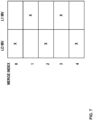
- FIGS. 2A and 2B are conceptual diagram illustrating an example quadtree binary tree (QTBT) structure 130, and a corresponding coding tree unit (CTU) 132.
- the solid lines represent quadtree splitting, and dotted lines indicate binary tree splitting.
- each split (i.e., non-leaf) node of the binary tree one flag is signaled to indicate which splitting type (i.e., horizontal or vertical) is used, where 0 indicates horizontal splitting and 1 indicates vertical splitting in this example.
- splitting type i.e., horizontal or vertical
- video encoder 200 may encode, and video decoder 300 may decode, syntax elements (such as splitting information) for a region tree level (i.e., the first level) of QTBT structure 130 (i.e., the solid lines) and syntax elements (such as splitting information) for a prediction tree level (i.e., the second level) of QTBT structure 130 (i.e., the dashed lines).
- Video encoder 200 may encode, and video decoder 300 may decode, video data, such as prediction and transform data, for CUs represented by terminal leaf nodes of QTBT structure 130.
- CTU 132 of FIG. 2B may be associated with parameters defining sizes of blocks corresponding to nodes of QTBT structure 130 at the first and second levels. These parameters may include a CTU size (representing a size of CTU 132 in samples), a minimum quadtree size (MinQTSize, representing a minimum allowed quadtree leaf node size), a maximum binary tree size (MaxBTSize, representing a maximum allowed binary tree root node size), a maximum binary tree depth (MaxBTDepth, representing a maximum allowed binary tree depth), and a minimum binary tree size (MinBTSize, representing the minimum allowed binary tree leaf node size).
- CTU size representing a size of CTU 132 in samples
- MinQTSize representing a minimum allowed quadtree leaf node size
- MaxBTSize representing a maximum binary tree root node size
- MaxBTDepth representing a maximum allowed binary tree depth
- MinBTSize representing the minimum allowed binary tree leaf node size
- the root node of a QTBT structure corresponding to a CTU may have four child nodes at the first level of the QTBT structure, each of which may be partitioned according to quadtree partitioning. That is, nodes of the first level are either leaf nodes (having no child nodes) or have four child nodes.
- the example of QTBT structure 130 represents such nodes as including the parent node and child nodes having solid lines for branches. If nodes of the first level are not larger than the maximum allowed binary tree root node size (MaxBTSize), then the nodes can be further partitioned by respective binary trees.
- MaxBTSize maximum allowed binary tree root node size
- the binary tree splitting of one node can be iterated until the nodes resulting from the split reach the minimum allowed binary tree leaf node size (MinBTSize) or the maximum allowed binary tree depth (MaxBTDepth).
- MinBTSize minimum allowed binary tree leaf node size
- MaxBTDepth maximum allowed binary tree depth
- the example of QTBT structure 130 represents such nodes as having dashed lines for branches.
- the binary tree leaf node is referred to as a coding unit (CU), which is used for prediction (e.g., intra-picture or inter-picture prediction) and transform, without any further partitioning.
- CUs may also be referred to as "video blocks" or "blocks.”
- the CTU size is set as 128x128 (luma samples and two corresponding 64x64 chroma samples), the MinQTSize is set as 16x16, the MaxBTSize is set as 64x64, the MinBTSize (for both width and height) is set as 4, and the MaxBTDepth is set as 4.
- the quadtree partitioning is applied to the CTU first to generate quad-tree leaf nodes.
- the quadtree leaf nodes may have a size from 16 ⁇ 16 (i.e., the MinQTSize) to 128 ⁇ 128 (i.e., the CTU size).
- the quadtree leaf node is 128128, it will not be further split by the binary tree, since the size exceeds the MaxBTSize (i.e., 64 ⁇ 64, in this example). Otherwise, the quadtree leaf node will be further partitioned by the binary tree. Therefore, the quadtree leaf node is also the root node for the binary tree and has the binary tree depth as 0. When the binary tree depth reaches MaxBTDepth (4, in this example), no further splitting is permitted. When the binary tree node has width equal to MinBTSize (4, in this example), it implies that no further vertical splitting is permitted. Similarly, a binary tree node having a height equal to MinBTSize implies that no further horizontal splitting is permitted for that binary tree node. As noted above, leaf nodes of the binary tree are referred to as CUs and are further processed according to prediction and transform without further partitioning.
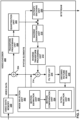
- FIG. 3 is a block diagram illustrating an example video encoder 200 that may perform the techniques of this disclosure.
- FIG. 3 is provided for purposes of explanation and should not be considered limiting of the techniques as broadly exemplified and described in this disclosure.
- this disclosure describes video encoder 200 in the context of video coding standards such as the HEVC video coding standard and the H.266 video coding standard in development.
- video coding standards such as the HEVC video coding standard and the H.266 video coding standard in development.
- the techniques of this disclosure are not limited to these video coding standards, and are applicable generally to video encoding and decoding.
- video encoder 200 includes video data memory 230, mode selection unit 202, residual generation unit 204, transform processing unit 206, quantization unit 208, inverse quantization unit 210, inverse transform processing unit 212, reconstruction unit 214, filter unit 216, decoded picture buffer (DPB) 218, and entropy encoding unit 220.
- Any or all of video data memory 230, mode selection unit 202, residual generation unit 204, transform processing unit 206, quantization unit 208, inverse quantization unit 210, inverse transform processing unit 212, reconstruction unit 214, filter unit 216, DPB 218, and entropy encoding unit 220 may be implemented in one or more processors or in processing circuitry.
- video encoder 200 may include additional or alternative processors or processing circuitry to perform these and other functions.
- Video data memory 230 may store video data to be encoded by the components of video encoder 200.
- Video encoder 200 may receive the video data stored in video data memory 230 from, for example, video source 104 ( FIG. 1 ).
- DPB 218 may act as a reference picture memory that stores reference video data for use in prediction of subsequent video data by video encoder 200.
- Video data memory 230 and DPB 218 may be formed by any of a variety of memory devices, such as dynamic random access memory (DRAM), including synchronous DRAM (SDRAM), magnetoresistive RAM (MRAM), resistive RAM (RRAM), or other types of memory devices.
- Video data memory 230 and DPB 218 may be provided by the same memory device or separate memory devices.
- video data memory 230 may be on-chip with other components of video encoder 200, as illustrated, or off-chip relative to those components.
- reference to video data memory 230 should not be interpreted as being limited to memory internal to video encoder 200, unless specifically described as such, or memory external to video encoder 200, unless specifically described as such. Rather, reference to video data memory 230 should be understood as reference memory that stores video data that video encoder 200 receives for encoding (e.g., video data for a current block that is to be encoded). Memory 106 of FIG. 1 may also provide temporary storage of outputs from the various units of video encoder 200.
- the various units of FIG. 3 are illustrated to assist with understanding the operations performed by video encoder 200.
- the units may be implemented as fixed-function circuits, programmable circuits, or a combination thereof.
- Fixed-function circuits refer to circuits that provide particular functionality, and are preset on the operations that can be performed.
- Programmable circuits refer to circuits that can be programmed to perform various tasks, and provide flexible functionality in the operations that can be performed.
- programmable circuits may execute software or firmware that cause the programmable circuits to operate in the manner defined by instructions of the software or firmware.
- Fixed-function circuits may execute software instructions (e.g., to receive parameters or output parameters), but the types of operations that the fixed-function circuits perform are generally immutable.
- the one or more of the units may be distinct circuit blocks (fixed-function or programmable), and in some examples, the one or more units may be integrated circuits.
- Video encoder 200 may include arithmetic logic units (ALUs), elementary function units (EFUs), digital circuits, analog circuits, and/or programmable cores, formed from programmable circuits.
- ALUs arithmetic logic units
- EFUs elementary function units
- digital circuits analog circuits
- programmable cores formed from programmable circuits.
- memory 106 FIG. 1
- memory 106 FIG. 1
- Video data memory 230 is configured to store received video data.
- Video encoder 200 may retrieve a picture of the video data from video data memory 230 and provide the video data to residual generation unit 204 and mode selection unit 202.
- Video data in video data memory 230 may be raw video data that is to be encoded.
- Mode selection unit 202 includes a motion estimation unit 222, motion compensation unit 224, and an intra-prediction unit 226. Mode selection unit 202 may include additional functional units to perform video prediction in accordance with other prediction modes. As examples, mode selection unit 202 may include a palette unit, an intra-block copy unit (which may be part of motion estimation unit 222 and/or motion compensation unit 224), an affine unit, a linear model (LM) unit, or the like.
- LM linear model
- Mode selection unit 202 generally coordinates multiple encoding passes to test combinations of encoding parameters and resulting rate-distortion values for such combinations.
- the encoding parameters may include partitioning of CTUs into CUs, prediction modes for the CUs, transform types for residual data of the CUs, quantization parameters for residual data of the CUs, and so on.
- Mode selection unit 202 may ultimately select the combination of encoding parameters having rate-distortion values that are better than the other tested combinations.
- Video encoder 200 may partition a picture retrieved from video data memory 230 into a series of CTUs, and encapsulate one or more CTUs within a slice.
- Mode selection unit 202 may partition a CTU of the picture in accordance with a tree structure, such as the QTBT structure or the quad-tree structure of HEVC described above.
- video encoder 200 may form one or more CUs from partitioning a CTU according to the tree structure.
- Such a CU may also be referred to generally as a "video block" or "block.”
- mode selection unit 202 also controls the components thereof (e.g., motion estimation unit 222, motion compensation unit 224, and intra-prediction unit 226) to generate a prediction block for a current block (e.g., a current CU, or in HEVC, the overlapping portion of a PU and a TU).
- motion estimation unit 222 may perform a motion search to identify one or more closely matching reference blocks in one or more reference pictures (e.g., one or more previously coded pictures stored in DPB 218).
- motion estimation unit 222 may calculate a value representative of how similar a potential reference block is to the current block, e.g., according to sum of absolute difference (SAD), sum of squared differences (SSD), mean absolute difference (MAD), mean squared differences (MSD), or the like. Motion estimation unit 222 may generally perform these calculations using sample-by-sample differences between the current block and the reference block being considered. Motion estimation unit 222 may identify a reference block having a lowest value resulting from these calculations, indicating a reference block that most closely matches the current block.
- SAD sum of absolute difference
- SSD sum of squared differences
- MAD mean absolute difference
- MSD mean squared differences
- Motion estimation unit 222 may form one or more motion vectors (MVs) that defines the positions of the reference blocks in the reference pictures relative to the position of the current block in a current picture. Motion estimation unit 222 may then provide the motion vectors to motion compensation unit 224. For example, for uni-directional inter-prediction, motion estimation unit 222 may provide a single motion vector, whereas for bi-directional inter-prediction, motion estimation unit 222 may provide two motion vectors. Motion compensation unit 224 may then generate a prediction block using the motion vectors. In some examples, motion compensation unit 224 may form a prediction block using techniques described herein for geometric partition mode with harmonized motion field storage and motion compensation. For example, motion compensation unit 224 may retrieve data of the reference block using the motion vector.
- MVs motion vectors
- motion compensation unit 224 may interpolate values for the prediction block according to one or more interpolation filters. Moreover, for bi-directional inter-prediction, motion compensation unit 224 may retrieve data for two reference blocks identified by respective motion vectors and combine the retrieved data, e.g., through sample-by-sample averaging or weighted averaging.
- intra-prediction unit 226 may generate the prediction block from samples neighboring the current block. For example, for directional modes, intra-prediction unit 226 may generally mathematically combine values of neighboring samples and populate these calculated values in the defined direction across the current block to produce the prediction block. As another example, for DC mode, intra-prediction unit 226 may calculate an average of the neighboring samples to the current block and generate the prediction block to include this resulting average for each sample of the prediction block.
- Mode selection unit 202 may apply geometric partition mode to generate a first partition of the current block of video data and a second partition of the block of video data.
- node selection unit 202 may select a split line comprising an angle and a displacement (e.g., a horizontal displacement from a center of the current block, a vertical displacement from the center of the current block, or a displacement from the center of the current block).
- Mode selection unit 202 may cause entropy encoding unit 220 to signal an indication (e.g., an index) of the split line.
- Mode selection unit 202 may generate the first partition using first motion information for the first partition and generate the second partition using second motion information for the second partition.
- Mode selection unit 202 may determine geometric mode weights for the current block using the angle of the split line. For example, mode selection unit 202 may apply a weight map that applies a weight to values of the current block consistent with the weights illustrated in the example of FIG. 8 relative to the split line.
- Mode selection unit 202 may determine a final prediction block using the geometric partition mode weights. For example, mode selection unit 202 may apply a respective geometric partition mode weight to each co-located sample of the first prediction block and the second prediction block to determine a final value for a sample of a final prediction block for the current block.
- Mode selection unit 202 provides the prediction block to residual generation unit 204.
- Residual generation unit 204 receives a raw, unencoded version of the current block from video data memory 230 and the final prediction block from mode selection unit 202. Residual generation unit 204 calculates sample-by-sample differences between the current block and the final prediction block. The resulting sample-by-sample differences define a residual block for the current block.
- residual generation unit 204 may also determine differences between sample values in the residual block to generate a residual block using residual differential pulse code modulation (RDPCM).
- RPCM residual differential pulse code modulation
- residual generation unit 204 may be formed using one or more subtractor circuits that perform binary subtraction.
- each PU may be associated with a luma prediction unit and corresponding chroma prediction units.
- Video encoder 200 and video decoder 300 may support PUs having various sizes. As indicated above, the size of a CU may refer to the size of the luma coding block of the CU and the size of a PU may refer to the size of a luma prediction unit of the PU. Assuming that the size of a particular CU is 2Nx2N, video encoder 200 may support PU sizes of 2Nx2N or NxN for intra prediction, and symmetric PU sizes of 2Nx2N, 2NxN, Nx2N, NxN, or similar for inter prediction. Video encoder 200 and video decoder 300 may also support asymmetric partitioning for PU sizes of 2NxnU, 2NxnD, nLx2N, and nRx2N for inter prediction.
- each CU may be associated with a luma coding block and corresponding chroma coding blocks.
- the size of a CU may refer to the size of the luma coding block of the CU.
- the video encoder 200 and video decoder 300 may support CU sizes of 2Nx2N, 2NxN, or Nx2N.
- mode selection unit 202 For other video coding techniques such as an intra-block copy mode coding, an affine-mode coding, and linear model (LM) mode coding, as a few examples, mode selection unit 202, via respective units associated with the coding techniques, generates a prediction block for the current block being encoded. In some examples, such as palette mode coding, mode selection unit 202 may not generate a prediction block, and instead generate syntax elements that indicate the manner in which to reconstruct the block based on a selected palette. In such modes, mode selection unit 202 may provide these syntax elements to entropy encoding unit 220 to be encoded.
- mode selection unit 202 via respective units associated with the coding techniques, generates a prediction block for the current block being encoded.
- mode selection unit 202 may not generate a prediction block, and instead generate syntax elements that indicate the manner in which to reconstruct the block based on a selected palette. In such modes, mode selection unit 202 may provide these syntax elements to entropy encoding unit 220 to be encoded.
- Transform processing unit 206 applies one or more transforms to the residual block to generate a block of transform coefficients (referred to herein as a "transform coefficient block").
- Transform processing unit 206 may apply various transforms to a residual block to form the transform coefficient block.
- transform processing unit 206 may apply a discrete cosine transform (DCT), a directional transform, a Karhunen-Loeve transform (KLT), or a conceptually similar transform to a residual block.
- transform processing unit 206 may perform multiple transforms to a residual block, e.g., a primary transform and a secondary transform, such as a rotational transform.
- transform processing unit 206 does not apply transforms to a residual block.
- Inverse quantization unit 210 and inverse transform processing unit 212 may apply inverse quantization and inverse transforms to a quantized transform coefficient block, respectively, to reconstruct a residual block from the transform coefficient block.
- Reconstruction unit 214 may produce a reconstructed block corresponding to the current block (albeit potentially with some degree of distortion) based on the reconstructed residual block and a prediction block generated by mode selection unit 202. For example, reconstruction unit 214 may add samples of the reconstructed residual block to corresponding samples from the prediction block generated by mode selection unit 202 to produce the reconstructed block.
- Filter unit 216 may perform one or more filter operations on reconstructed blocks. For example, filter unit 216 may perform deblocking operations to reduce blockiness artifacts along edges of CUs. Operations of filter unit 216 may be skipped, in some examples.
- Video encoder 200 stores reconstructed blocks in DPB 218. For instance, in examples where operations of filter unit 216 are not needed, reconstruction unit 214 may store reconstructed blocks to DPB 218. In examples where operations of filter unit 216 are needed, filter unit 216 may store the filtered reconstructed blocks to DPB 218.
- Motion estimation unit 222 and motion compensation unit 224 may retrieve a reference picture from DPB 218, formed from the reconstructed (and potentially filtered) blocks, to inter-predict blocks of subsequently encoded pictures.
- intra-prediction unit 226 may use reconstructed blocks in DPB 218 of a current picture to intra-predict other blocks in the current picture.
- entropy encoding unit 220 may entropy encode syntax elements received from other functional components of video encoder 200. For example, entropy encoding unit 220 may entropy encode quantized transform coefficient blocks from quantization unit 208. As another example, entropy encoding unit 220 may entropy encode prediction syntax elements (e.g., motion information for inter-prediction or intra-mode information for intra-prediction) from mode selection unit 202. Entropy encoding unit 220 may perform one or more entropy encoding operations on the syntax elements, which are another example of video data, to generate entropy-encoded data.
- prediction syntax elements e.g., motion information for inter-prediction or intra-mode information for intra-prediction
- entropy encoding unit 220 may perform a context-adaptive variable length coding (CAVLC) operation, a CABAC operation, a variable-to-variable (V2V) length coding operation, a syntax-based context-adaptive binary arithmetic coding (SBAC) operation, a Probability Interval Partitioning Entropy (PIPE) coding operation, an Exponential-Golomb encoding operation, or another type of entropy encoding operation on the data.
- entropy encoding unit 220 may operate in bypass mode where syntax elements are not entropy encoded.
- Video encoder 200 may output a bitstream that includes the entropy encoded syntax elements needed to reconstruct blocks of a slice or picture.
- entropy encoding unit 220 may output the bitstream.
- the operations described above are described with respect to a block. Such description should be understood as being operations for a luma coding block and/or chroma coding blocks.
- the luma coding block and chroma coding blocks are luma and chroma components of a CU.
- the luma coding block and the chroma coding blocks are luma and chroma components of a PU.
- operations performed with respect to a luma coding block need not be repeated for the chroma coding blocks.
- operations to identify a motion vector (MV) and reference picture for a luma coding block need not be repeated for identifying an MV and reference picture for the chroma blocks. Rather, the MV for the luma coding block may be scaled to determine the MV for the chroma blocks, and the reference picture may be the same.
- the intra-prediction process may be the same for the luma coding block and the chroma coding blocks.
- Video encoder 200 represents an example of a device configured to encode video data including a memory configured to store video data, and one or more processing units implemented in circuitry and configured to determine that a geometric partition mode is enabled for a current block of the video data and determine a split line dividing the current block into a first partition and a second partition, wherein, to determine the split line, video encoder 200 is configured to select an angle for the split line from a plurality of angles, each angle of the plurality of angles corresponding to an N:M ratio of samples of the current block, wherein N and M are integers, and wherein the split line is not at a corner of the current block.
- Video encoder 200 is further configured to determine geometric mode weights for the current block using the angle of the split line and generate a first prediction block using motion information for the first partition. Video encoder 200 is further configured to generate a second prediction block using motion information for the second partition and apply the geometric partition mode weights to samples of the first prediction block and to samples of the second prediction block to determine a final prediction block for the current block. Video encoder 200 is further configured to generate a residual block for the current block of video data based on differences between the current block of the video data and the final prediction block and encode the residual block.
- FIG. 4 is a block diagram illustrating an example video decoder 300 that may perform the techniques of this disclosure.
- FIG. 4 is provided for purposes of explanation and is not limiting on the techniques as broadly exemplified and described in this disclosure.
- this disclosure describes video decoder 300 according to the techniques of VVC and HEVC.
- the techniques of this disclosure may be performed by video coding devices that are configured to other video coding standards.
- video decoder 300 includes coded picture buffer (CPB) memory 320, entropy decoding unit 302, prediction processing unit 304, inverse quantization unit 306, inverse transform processing unit 308, reconstruction unit 310, filter unit 312, and decoded picture buffer (DPB) 314.
- CPB memory 320, entropy decoding unit 302, prediction processing unit 304, inverse quantization unit 306, inverse transform processing unit 308, reconstruction unit 310, filter unit 312, and DPB 314 may be implemented in one or more processors or in processing circuitry.
- video decoder 300 may include additional or alternative processors or processing circuitry to perform these and other functions.
- Prediction processing unit 304 includes motion compensation unit 316 and intra-prediction unit 318. Prediction processing unit 304 may include additional units to perform prediction in accordance with other prediction modes. As examples, prediction processing unit 304 may include a palette unit, an intra-block copy unit (which may form part of motion compensation unit 316), an affine unit, a linear model (LM) unit, or the like. In other examples, video decoder 300 may include more, fewer, or different functional components.
- CPB memory 320 may store video data, such as an encoded video bitstream, to be decoded by the components of video decoder 300.
- the video data stored in CPB memory 320 may be obtained, for example, from computer-readable medium 110 ( FIG. 1 ).
- CPB memory 320 may include a CPB that stores encoded video data (e.g., syntax elements) from an encoded video bitstream.
- CPB memory 320 may store video data other than syntax elements of a coded picture, such as temporary data representing outputs from the various units of video decoder 300.
- DPB 314 generally stores decoded pictures, which video decoder 300 may output and/or use as reference video data when decoding subsequent data or pictures of the encoded video bitstream.
- CPB memory 320 and DPB 314 may be formed by any of a variety of memory devices, such as DRAM, including SDRAM, MRAM, RRAM, or other types of memory devices.
- CPB memory 320 and DPB 314 may be provided by the same memory device or separate memory devices.
- CPB memory 320 may be on-chip with other components of video decoder 300, or off-chip relative to those components.
- video decoder 300 may retrieve coded video data from memory 120 ( FIG. 1 ). That is, memory 120 may store data as discussed above with CPB memory 320. Likewise, memory 120 may store instructions to be executed by video decoder 300, when some or all of the functionality of video decoder 300 is implemented in software to be executed by processing circuitry of video decoder 300.
- the various units shown in FIG. 4 are illustrated to assist with understanding the operations performed by video decoder 300.
- the units may be implemented as fixed-function circuits, programmable circuits, or a combination thereof. Similar to FIG. 3 , fixed-function circuits refer to circuits that provide particular functionality, and are preset on the operations that can be performed.
- Programmable circuits refer to circuits that can be programmed to perform various tasks, and provide flexible functionality in the operations that can be performed. For instance, programmable circuits may execute software or firmware that cause the programmable circuits to operate in the manner defined by instructions of the software or firmware.
- Fixed-function circuits may execute software instructions (e.g., to receive parameters or output parameters), but the types of operations that the fixed-function circuits perform are generally immutable.
- the one or more of the units may be distinct circuit blocks (fixed-function or programmable), and in some examples, the one or more units may be integrated circuits.
- Video decoder 300 may include ALUs, EFUs, digital circuits, analog circuits, and/or programmable cores formed from programmable circuits. In examples where the operations of video decoder 300 are performed by software executing on the programmable circuits, on-chip or off-chip memory may store instructions (e.g., object code) of the software that video decoder 300 receives and executes.
- instructions e.g., object code
- Entropy decoding unit 302 may receive encoded video data from the CPB and entropy decode the video data to reproduce syntax elements.
- Prediction processing unit 304, inverse quantization unit 306, inverse transform processing unit 308, reconstruction unit 310, and filter unit 312 may generate decoded video data based on the syntax elements extracted from the bitstream.
- video decoder 300 reconstructs a picture on a block-by-block basis.
- Video decoder 300 may perform a reconstruction operation on each block individually (where the block currently being reconstructed, i.e., decoded, may be referred to as a "current block").
- Entropy decoding unit 302 may entropy decode syntax elements defining quantized transform coefficients of a quantized transform coefficient block, as well as transform information, such as a quantization parameter (QP) and/or transform mode indication(s).
- Inverse quantization unit 306 may use the QP associated with the quantized transform coefficient block to determine a degree of quantization and, likewise, a degree of inverse quantization for inverse quantization unit 306 to apply.
- Inverse quantization unit 306 may, for example, perform a bitwise left-shift operation to inverse quantize the quantized transform coefficients. Inverse quantization unit 306 may thereby form a transform coefficient block including transform coefficients.
- inverse transform processing unit 308 may apply one or more inverse transforms to the transform coefficient block to generate a residual block associated with the current block.
- inverse transform processing unit 308 may apply an inverse DCT, an inverse integer transform, an inverse Karhunen-Loeve transform (KLT), an inverse rotational transform, an inverse directional transform, or another inverse transform to the coefficient block.
- KLT Karhunen-Loeve transform
- prediction processing unit 304 generates a prediction block according to prediction information syntax elements that were entropy decoded by entropy decoding unit 302. For example, if the prediction information syntax elements indicate that the current block is inter-predicted, motion compensation unit 316 may generate the prediction block. In this case, the prediction information syntax elements may indicate a reference picture in DPB 314 from which to retrieve a reference block, as well as a motion vector identifying a location of the reference block in the reference picture relative to the location of the current block in the current picture. Motion compensation unit 316 may generally perform the inter-prediction process in a manner that is substantially similar to that described with respect to motion compensation unit 224 ( FIG. 3 ). In some examples, motion compensation unit 316 may form a prediction block using techniques described herein for geometric partition mode with harmonized motion field storage and motion compensation.
- intra-prediction unit 318 may generate the prediction block according to an intra-prediction mode indicated by the prediction information syntax elements. Again, intra-prediction unit 318 may generally perform the intra-prediction process in a manner that is substantially similar to that described with respect to intra-prediction unit 226 ( FIG. 3 ). Intra-prediction unit 318 may retrieve data of neighboring samples to the current block from DPB 314.
- Prediction processing unit 304 may receive an indication (e.g., an index) of the split line. Prediction processing unit 304 may apply geometric partition mode to generate a first partition of the current block of video data and a second partition of the block of video data using the split line. In general, prediction processing unit 304 may determine an split line comprising an angle and a displacement (e.g., a horizontal displacement from a center of the current block, a vertical displacement from the center of the current block, or a displacement from the center of the current block).
- a displacement e.g., a horizontal displacement from a center of the current block, a vertical displacement from the center of the current block, or a displacement from the center of the current block.
- Prediction processing unit 304 may generate a first prediction block using motion information for the first partition determined using first motion information for the first partition and generate a second prediction block using motion information for the second partition using second motion information for the second partition. Prediction processing unit 304 may determine geometric mode weights for the current block using the angle of the split line. For example, prediction processing unit 304 may apply a weight map that applies a weight to values of the current block consistent with the weights illustrated in the example of FIG. 8 relative to the split line. Prediction processing unit 304 may determine a final prediction block using the geometric partition mode weights. For example, prediction processing unit 304 may apply a respective geometric partition mode weight to each co-located sample of the first prediction block and the second prediction to determine a value for a sample of a final prediction block for the current block.
- Reconstruction unit 310 may reconstruct the current block using the prediction block and the residual block. For example, reconstruction unit 310 may add samples of the residual block to corresponding samples of the prediction block to reconstruct the current block.
- Filter unit 312 may perform one or more filter operations on reconstructed blocks. For example, filter unit 312 may perform deblocking operations to reduce blockiness artifacts along edges of the reconstructed blocks. Operations of filter unit 312 are not necessarily performed in all examples.
- Video decoder 300 may store the reconstructed blocks in DPB 314. For instance, in examples where operations of filter unit 312 are not performed, reconstruction unit 310 may store reconstructed blocks to DPB 314. In examples where operations of filter unit 312 are performed, filter unit 312 may store the filtered reconstructed blocks to DPB 314. As discussed above, DPB 314 may provide reference information, such as samples of a current picture for intra-prediction and previously decoded pictures for subsequent motion compensation, to prediction processing unit 304. Moreover, video decoder 300 may output decoded pictures from DPB for subsequent presentation on a display device, such as display device 118 of FIG. 1 .
- video decoder 300 represents an example of a video decoding device including a memory configured to store video data, and one or more processing units implemented in circuitry and configured to determine that a geometric partition mode is enabled for a current block of the video data and determine a split line dividing the current block into a first partition and a second partition, wherein, to determine the split line, video decoder 300 is configured to select an angle for the split line from a plurality of angles, each angle of the plurality of angles corresponding to an N:M ratio of samples of the current block, wherein N and M are integers, and wherein the split line is not at a corner of the current block.
- Video decoder 300 is further configured to determine geometric mode weights for the current block using the angle of the split line and generate a first prediction block using motion information for the first partition. Video decoder 300 is further configured to generate a second prediction block using motion information for the second partition and apply the geometric partition mode weights to samples of the first prediction block and to samples of the second prediction block to determine a final prediction block for the current block. Video decoder 300 is further configured to decode a residual block for the current block and combine the final prediction block and the residual block to decode the current block.
- Video coding standards may include, for example, but are not limited to, ITU-T H.261, ISO/IEC MPEG-1 Visual, ITU-T H.262 or ISO/IEC MPEG-2 Visual, ITU-T H.263, ISO/IEC MPEG-4 Visual and ITU-T H.264 (also known as ISO/IEC MPEG-4 AVC), including its Scalable Video Coding (SVC) and Multiview Video Coding (MVC) extensions.
- SVC Scalable Video Coding
- MVC Multiview Video Coding
- HEVC High Efficiency Video Coding
- JCT-VC Joint Collaboration Team on Video Coding
- MPEG ISO/IEC Motion Picture Experts Group
- VTM 6 Versatile Video Coding and Test Model 6
- FIG. 5 is a conceptual diagram illustrating example triangle partition based inter prediction.
- VTM 5 Versatile Video Coding and Test Model 5
- JVET Joint Video Experts Team
- a video coder e.g., video encoder 200 and video decoder 300
- MMVD Motion Vector Differences
- CIIP Combined inter and intra prediction
- video encoder 200 may signal a flag to indicate whether the triangle partition mode is applied or not.
- video encoder 200 and video decoder 300 may be configured to split the CU evenly into two triangle shaped partitions, using either the diagonal split of block 500 or the anti-diagonal split of block 502. As shown, the resulting split line is arranged in corners of block 500.
- Video encoder 200 and video decoder 300 may be configured to inter-predict each triangle partition in the CU using each triangle's own motion; only uni-prediction is allowed for each partition, that is, each partition has one motion vector and one reference index.
- Video encoder 200 and video decoder 300 may be configured to apply the uni-prediction motion constraint to ensure only two motion compensated prediction are needed for each CU, which is the same as bi-prediction of a CU.
- Video encoder 200 and video decoder 300 may be configured to derive the uni-prediction motion for each partition from a uni-prediction candidate list constructed using uni-prediction candidate list construction (see FIG. 6 ).
- the CU-level flag indicates that the current CU is coded using the triangle partition mode.
- video encoder 200 may be configured to signal a flag indicating the direction of the triangle partition (e.g., diagonal or anti-diagonal), and two merge indices (e.g., one for each triangle partition).
- video encoder 200 and video decoder 300 may be configured to adjust the sample values along the diagonal or anti-diagonal edge using a blending processing with adaptive weights.
- video encoder 200 and video decoder 300 may be configured to apply a quantization process to the whole CU as in other prediction modes.
- video encoder 200 and video decoder 300 may be configured to store the motion field of a CU predicted using the triangle partition mode in 4x4 units using blending along a triangle partition edge (see FIG. 8 ).
- Video encoder 200 and video decoder 300 may be configured to collect the motion vectors of the seven neighboring blocks and put the motion vectors of the seven neighboring blocks into the uni-prediction candidate list according to the following order: first, the motion vectors of the uni-predicted neighboring blocks; then, for the bi-predicted neighboring blocks, the L0 motion vectors (that is, the L0 motion vector part of the bi-prediction MV), the L1 motion vectors (that is, the L1 motion vector part of the bi-prediction MV), and averaged motion vectors of the L0 and L1 motion vectors of the bi-prediction MVs. If the number of candidates is less than five, video encoder 200 and video decoder 300 may be configured to add a zero motion vector to the end of the list.
- FIG. 7 is a conceptual diagram illustrating example uni-prediction MV selection for triangle partition mode.
- TPM triangle partition mode
- video encoder 200 and video decoder 300 may be configured to derive the uni-prediction motion vector from the merge candidate list.
- video encoder 200 and video decoder 300 may be configured to use the candidate's LX MV (with X equal to the parity of the merge candidate index value) as the uni-prediction motion vector for triangle partition mode. These motion vectors are marked with "x" in FIG. 7 .
- FIG. 8 is a conceptual diagram illustrating example weights used in the blending process.
- the example blending process of FIG. 8 may be referred to herein as section 2.2.3 blending along the triangle partition edge, or simply section 2.2.3.
- a video coder (e.g., video encoder 200 and/or video decoder 300) may be configured to perform the example pixel blending of FIG. 8 with one set of weights as shown in FIG. 8 .
- the video coder may be configured to generate the pixels in blending areas by, for example, weighted averaging of the collocated motion compensated pixels based on motion information of the two triangular partitions.
- collocated pixels may refer to a first pixel of a first prediction block determined using a first partition (e.g., a first triangle-shaped partition) that is positioned at a same pixel position as a second pixel of a second prediction block determined using a second partition (e.g., a second triangle-shaped partition).
- a video coder may apply pixel blending using a set of weights to generate a final prediction block for the chroma components of the block of video data.
- the video coder may determine weighted averages, using the set of weights, of collocated motion compensated pixels (shown as "Pi") of a first partition block determined using motion information for a first triangle-shaped partition and collocated motion compensated pixels (shown as "P 2 ") of a second partition block determined using motion information for a second triangle-shaped partition.
- a video coder may be configured to determine motion information for the first triangle-shaped partition by performing a motion search to identify a reference block that closely matches the first triangle-shaped partition, e.g., in terms of differences between the first triangle-shaped partition and a reference block.
- the video coder may calculate a difference metric using a sum of absolute difference (SAD), sum of squared differences (SSD), mean absolute difference (MAD), mean squared differences (MSD), or other such difference calculations to determine whether a reference block closely matches the first triangle-shaped partition.
- the video coder may predict a first prediction block using uni-directional prediction or bi-directional prediction. Pixels of the first prediction block may be referred to herein as "Pi" and may also be referred to herein as samples of the first prediction block.
- a video coder may be configured to determine motion information for the second triangle-shaped partition by performing a motion search to identify a reference block that closely matches the second triangle-shaped partition, e.g., in terms of differences between the first triangle-shaped partition and a reference block.
- the video coder may calculate a difference metric using a sum of absolute difference (SAD), sum of squared differences (SSD), mean absolute difference (MAD), mean squared differences (MSD), or other such difference calculations to determine whether a reference block closely matches the second triangle-shaped partition.
- the video coder may predict a second prediction block using uni-directional prediction or bi-directional prediction. Pixels of the second prediction block may be referred to herein as "P 2 " and may also be referred to herein as samples of the second prediction block.
- a video coder may determine a pixel value P for pixels marked with "2" of prediction block 537 (also referred to herein as “final prediction block 537”) for luma components and/or prediction block 538 "final prediction block 538") for luma components by calculating the respective value P for each pixel according to EQUATION 1.
- P 2 8 ⁇ P 1 + 6 8 ⁇ P 2
- P 1 is a first reference pixel value of a first pixel of the first prediction block that is collocated with the respective pixel marked with "2" in this example
- P 2 is a second reference pixel value of a second pixel of the second prediction block that is collocated with the respective pixel marked with "2" in this example.
- a video coder may determine a pixel value P for pixels marked with "4" of prediction block 537 for luma components and/or prediction block 538 for luma components by calculating the respective value P for each pixel according to EQUATION 2.
- P 4 8 ⁇ P 1 + 4 8 ⁇ P 2
- P 1 is a first reference pixel value of a first pixel of the first prediction block that is collocated with the respective pixel marked with "4" in this example
- P 2 is a second reference pixel value of a second pixel of the second prediction block that is collocated with the respective pixel marked with "4" in this example.
- a video coder may determine a pixel value P for pixels marked with "7" of prediction block 537 for luma components and/or prediction block 538 for luma components by calculating the respective value P for each pixel according to EQUATION 3.
- P 7 8 ⁇ P 1 + 1 8 ⁇ P 2
- P 1 is a first reference pixel value of a first pixel of the first prediction block that is collocated with the respective pixel marked with "7” in this example
- P 2 is a second reference pixel value of a second pixel of the second prediction block that is collocated with the respective pixel marked with "7” in this example.
- a video coder e.g., video encoder 200 or video decoder 300
- P 1 8 ⁇ P 1 + 7 8 ⁇ P 2
- P 1 is a first reference pixel value of a first pixel of the first prediction block and where P 2 is a second reference pixel value of a second pixel of the second prediction block.
- a video coder may determine a pixel value P for pixels marked with "6" of prediction block 537 for luma components and/or prediction block 538 for luma components by calculating the respective value P for each pixel according to EQUATION 5.
- P 6 8 ⁇ P 1 + 2 8 ⁇ P 2 where P 1 is a first reference pixel value of a first pixel of the first prediction block and where P 2 is a second reference pixel value of a second pixel of the second prediction block.
- FIG. 8 shows an example set of weights ⁇ 7/8, 6/8, 4/8, 2/8, 1/8 ⁇ for luma and ⁇ 7/8, 4/8, 1/8 ⁇ for chroma
- other examples may use different weights.
- there may be two sets of weights and in each set chroma weights and luma weights may be defined separately:
- Video encoder 200 and video decoder 300 may be configured to store the motion vectors of a CU coded in triangle partition mode in 4x4 units. Depending on the position of each 4x4 unit, video encoder 200 and video decoder 300 may be configured to store either uni-prediction or bi-prediction motion vectors. In this example, Mv1 and Mv2 may represent uni-prediction motion vectors for partition 1 and partition 2, respectively.
- Partition 1 and 2 may be the triangle blocks sitting respectively on the upper-right corner and lower-left corner when CUs may be partitioned from top-left to lower-right (that is 45° split), while Mv1 and Mv2 become triangle blocks sitting respectively on the upper-left corner and lower-right corner when CUs are partitioned from top-right to lower-left (that is 135° split). If a 4x4 unit is located in the non-weighted area shown in the example of FIG. 9 , video encoder 200 and video decoder 300 may be configured to store either Mv1 or Mv2 for that 4x4 unit.
- video encoder 200 and video decoder 300 may be configured to store a bi-prediction motion vector.
- Video encoder 200 and video decoder 300 may be configured to derive the bi-prediction motion vector from Mv1 and Mv2 according to the following process:
- FIG. 9 is a conceptual diagram illustrating example triangle partition mode (TPM).
- a video coder e.g., video encoder 200 or video decoder 300
- diagonal split line 590 and anti-diagonal split line 511 are arranged at corners of a current block.
- the video coder may apply split lines at quantized angle between 0 and 360 degrees, with 11.25 degrees of separation and separation line displacement relatively to the center of the block.
- FIG. 9 illustrates an example of TPM as in VVC Draft and GPM as in Esenlik, et al. "Non-CE4: Geometrical partitioning for inter blocks Joint Video Experts Team (JVET) of ITU-T SG 16 WP 3 and ISO/IEC JTC 1/SC 29/WG 11, 15th Meeting: Gothenburg, SE, 3-12 July 2019, JVET-O0489-v4 (hereinafter "JVET-6 O0489").
- JVET-6 O0489 Joint Video Experts Team
- Geometric partitioning was introduced in JVET-O0489 as a proposed extension to the non-rectangular partitioning introduced by TPM.
- a video encoder or video decoder may apply the geometric partition mode (GEO) only to CUs coded in skip or merge mode, but not in MMVD or CIIP mode.
- GEO geometric partition mode
- a video encoder e.g., video encoder 200
- FIG. 9 illustrates TPM in VVC Draft 6 and additional shapes proposed for non-rectangular inter blocks.
- Overall number of GPM partitioning may be 140 possibilities. Additional signaling for GPM signals the angle ⁇ , and separation line displacement relatively to the center of the block ⁇ . ⁇ represents a quantized angle between 0 and 360 degrees, with 11.25 degrees of separation and ⁇ represents a distance with 5 different values.
- FIG. 10 is a conceptual diagram illustrating example GPM partitioning signaling.
- video encoder 200 may signal values for angle and separation line displacement relatively to the center of the block ⁇ for split line 515.
- video encoder 200 and video decoder 300 may be configured to allow GPM partitioning for inter for uni-predicted blocks not smaller than 8x8 in order to have the same memory bandwidth with bi- predicted blocks at decoder side.
- Motion vector prediction for GPM partitioning may be aligned with TPM.
- video encoder 200 and video decoder 300 may be configured to apply blending between two predictions on an inner boundary.
- a video encoder may signal the GPM mode as an additional merge mode.
- the geo_merge_idx0 and geo_merge_idx1 are coded using same CABAC contexts and binarization as TPM merge indices.
- the geo_partition_idx indicates the partition mode (out of 140 possibilities) and is coded using truncated binary binarization and bypass coding.
- video encoder 200 and video decoder 300 may be configured to select the TPM.
- the partitions of the GPM mode do not include partitions that can be obtained by TPM of binary splitting.
- the proposed signalling scheme is similar to intra mode singaling, where the TPM partitions correspond to most probable partitions and GPM modes correspond to remainder partitions.
- the geo_partition_idx is used as an index to the lookup table that stores the ⁇ and ⁇ pairs. As described above 140 bytes are necessary to store this table.
- the example blending operation for a luma block may be referred to herein as section 2.3.2 blending operation for a luma block, or simply section 2.3.2.
- video encoder 200 and video decoder 300 may be configured to obtain the final prediction of the coding block by weighted averaging of first uni-prediction and second uni-prediction according to sample weights.
- sampleWeight L x y 8 ⁇ GeoFilter distScaled if distFromLine > 0
- sample weights are implemented as a lookup table as in Table 2 as follows: Table 2 blending filter weights distScaled 0 1 2 3 4 5 6 7 8 9 10 11 12 13 14 GeoFilter[dist Scaled] 4 4 5 5 5 5 6 6 6 6 7 7 7 8
- Video encoder 200 and video decoder 300 may be configured to calculate the variable rho, displacementX and displacementY once per coding block
- Dis[] is a lookup table with 32 entries (8 bits resolution) that store cosine value
- video encoder 200 and video decoder 300 may be configured to calculate distFromLine by incrementing distFromLine for each sample with a value of 2 *Dis[displacementX] in a sample row and with a value of 2 *Dis[displacementX] from one sample row to the next. Therefore, slightly more than 1 additions per sample is used to obtain distFromLine value. Additionally minimum, absolute value and downshift operations may be used, which do not introduce any considerable complexity.
- Video encoder 200 and video decoder 300 may be configured to implement all operations of GPM using integer arithmetic.
- the computational complexity of GPM may be very similar to TPM. More details regarding the blending operation may be found at, for example, JVET-O0489.
- Video encoder 200 and video decoder 300 may be configured to subsample the sample weights calculated for the luma samples and use the sample weights calculated for the luma samples for chroma blending without any computation. Video encoder 200 and video decoder 300 may be configured to set the chroma sample weight at coordinate (x,y) equal to luma sample weight at coordinate (2x,2y) with respect to the top-left sample of luma block.
- Video encoder 200 and video decoder 300 may be configured to use a same merge list derivation process that is used for TPM for deriving motion vectors of each partition of the GPM block.
- video encoder 200 and video decoder 300 may be configured to predict each partition only by uni-prediction.
- Video encoder 200 and video decoder 300 may be configured to sum luma sample weights (which may be calculated by blending along the triangle partition edge as shown in FIG. 8 ) at the four corners of a 4x4 motion storage unit. Then, video encoder 200 and video decoder 300 may be configured to compare the sum with 2 thresholds to determine whether one of two uni-prediction motion information or bi-prediction motion information is stored. Video encoder 200 and video decoder 300 may be configured to derive the bi-prediction motion information using the same process as TPM.
- the current GPM design describes represents an extension to TPM. However, some differences may be harmonized during JVET 15th meeting in Goteborg. Harmonization of TPM and GPM motion field storage is discussed in the following.
- the TPM algorithm for motion field storage only uses the position of a 4x4 unit within the CU to determine which motion vector needs to be stored, while the GPM method uses the weights used for motion compensation for the storage. Moreover, if the current algorithm for motion field storage of GPM were to be applied to TPM, the TPM storage would end up modified. There are benefits to have a unified process of storage for both TPM and GPM processes.
- the motion field storage of GPM can be modified in the following way.
- Video encoder 200 and video decoder 300 may be configured to use the distance from the center of each 4x4 unit to the split line so that the same equation can be used for TPM motion field storage without changing the MV stored for TPM.
- sx_i represents a distance between a center of an i-th 4x4 block and a split line along the x direction
- sy_i represents a distance between a center of the i-th 4x4 block and a split line along the y direction
- d is an intermediate variable
- displacement, displacement Y, and rho represent the split line, which are calculated once per coding block
- distanceScaled represents a scaled distance between the center of the i-th 4x4 block and the split line
- tempMotionBuffer represents the "motion field storage of GEO," which may be 2 for a bidirectional prediction (e.g., using list 0 and list 1), 1 for uni-direction prediction (e.g., using only list 0 or only list 1), and 0 for uni-direction prediction (e.g., using only list 1 or only list 0).
- Video encoder 200 and video decoder 300 may be configured to apply scaling to achieve integer operations.
- video encoder 200 and video decoder 300 may be configured to derive displacementX, displacementY, Dis, and rho using a blending operation for a luma block (See Table 2) and tempMotionBuffer equals to 0 indicates storage of Mv0, equals to 1 to storage of Mv1 and equals to 2 indicates storage of biMv using motion field storage.
- video encoder 200 and video decoder 300 may be configured to derive displacementX, displacementY, Dis and rho according to the process described in section 2.3.2.
- tempMotionBuffer equals to 2 indicate storage of biMv using the process described in section 2.2.4.
- video encoder 200 and video decoder 300 may be configured to change the weights used for the blending part in GPM so that the weights used for the blending part in GPM use TPM weight process for blending along the triangle partition edge (see FIG. 9 ).
- video encoder 200 and video decoder 300 may be configured to change the weights used for the blending part in GPM so that the weights used for the blending part in GPM use TPM weight process described in section 2.2.3.
- video encoder 200 and video decoder 300 may be configured to identify a split edge, generate sub-block that includes the split edge arranged in within the sub-block to correspond to a TPM position, and derive GPM motion weights using a TPM weight processes.
- Video encoder 200 and video decoder 300 may be configured to change the angles used by GPM so that the angles used by GPM match TPM angles.
- video encoder 200 and video decoder 300 may be configured to use GPM to have equivalent angles to TPM (e.g., more than 32 angles).
- video encoder 200 and video decoder 300 may be configured to use GPM to select an angle for a split line from a plurality of angles, each angle of the plurality of angles corresponding to an N:M ratio of samples of the current block, wherein N and M are integers.
- N and M are integers.
- video encoder 200 and video decoder 300 may apply angles corresponding to a 1:2 ratio, 1:4 ratio, 1:1 ratio, 2:1 ratio, 0:1 ratio, or 1:0 ratio.
- Video encoder 200 and video decoder 300 may be configured to shift the start and end position of the weighted area with an offset to replicate GPM multiple offsets.
- a video coder e.g., video encoder 200 or video decoder 300
- the video coder may determine a weighted area based on the angle for the split line and shift the weighted area based on the distance offset from the center of the current block to generated a shifted weighted area.
- Video encoder 200 and video decoder 300 may be configured to use TPM angles from different block sizes along with GEO, to allow more GPM angles. Examples are presented in FIG. 11.
- FIG. 11 is a conceptual diagram illustrating example GPM harmonization with TPM.
- FIG. 12 is a flowchart illustrating an example method for encoding a current block.
- the current block may comprise a current CU.
- video encoder 200 FIGS. 1 and 3
- other devices may be configured to perform a method similar to that of FIG. 12 .
- video encoder 200 predicts the current block (350). For example, video encoder 200 may form a prediction block for the current block. In some examples, video encoder 200 may form a prediction block using techniques described herein for geometric partition mode. Video encoder 200 may then calculate a residual block for the current block (352). To calculate the residual block, video encoder 200 may calculate a difference between the original, unencoded block and the prediction block for the current block. Video encoder 200 may then transform and quantize coefficients of the residual block (354). Next, video encoder 200 may scan the quantized transform coefficients of the residual block (356). During the scan, or following the scan, video encoder 200 may entropy encode the transform coefficients (358). For example, video encoder 200 may encode the transform coefficients using CAVLC or CABAC. Video encoder 200 may then output the entropy encoded data of the block (360).
- FIG. 13 is a flowchart illustrating an example method for decoding a current block of video data.
- the current block may comprise a current CU.
- video decoder 300 FIGS. 1 and 4
- other devices may be configured to perform a method similar to that of FIG. 13 .
- Video decoder 300 may receive entropy encoded data for the current block, such as entropy encoded prediction information and entropy encoded data for coefficients of a residual block corresponding to the current block (370). Video decoder 300 may entropy decode the entropy encoded data to determine prediction information for the current block and to reproduce coefficients of the residual block (372). Video decoder 300 may predict the current block (374), e.g., using an intra- or inter-prediction mode as indicated by the prediction information for the current block, to calculate a prediction block for the current block. In some examples, video decoder 300 may form a prediction block using techniques described herein for geometric partition mode.
- Video decoder 300 may then inverse scan the reproduced coefficients (376), to create a block of quantized transform coefficients. Video decoder 300 may then inverse quantize and inverse transform the transform coefficients to produce a residual block (378). Video decoder 300 may ultimately decode the current block by combining the prediction block and the residual block (380).
- FIG. 14 is a conceptual diagram illustrating example GPM harmonization with TPM.
- the GPM angle for split line 381 has a width-to-height ratio that is not a multiple of 2. That is, split line 381 has a width-to-height ratio of 4 to 7.
- a width-to-height ratio that is not a multiple of 2 may be different from 4 to 7, for example, 3 to 7, 2 to 7, 3 to 8, and so on.
- FIG. 15 is a flowchart illustrating an example method for encoding a current block using a plurality of angles, each angle of the plurality of angles corresponding to an N:M ratio of samples of a current block, in accordance with the techniques of the disclosure.
- Video encoder 200 e.g., mode selection unit 202 may determine that a geometric partition mode is enabled for a current block of the video data (502).
- Video encoder 200 may determine a split line dividing the current block into a first partition and a second partition, wherein determining the split line comprises selecting an angle for the split line from a plurality of angles, each angle of the plurality of angles corresponding to an N:M ratio of samples of the current block, where N and M are integers, and where the split line is not at a corner of the current block (504).
- Video encoder 200 e.g., mode selection unit 202 may determine geometric mode weights for the current block using the angle of the split line (506).
- Video encoder 200 e.g., mode selection unit 202) may generate a first partition block using motion information for the first partition (508).
- Video encoder 200 may generate a second partition block using motion information for the second partition (510). Video encoder 200 (e.g., mode selection unit 202) may apply the geometric partition mode weights to samples of the first prediction block and to samples of the second prediction block to determine a final prediction block for the current block (512). Video encoder 200 (e.g., residual generation unit 204) may generate a residual block for the current block of video data based on differences between the current block of the video data and the final prediction block (514). Video encoder 200 (e.g., entropy encoding unit 220) may encode the residual block to generate an encoded residual block (516) and output the encoded residual block (518).
- Video encoder 200 e.g., mode selection unit 202
- Video encoder 200 may generate a second partition block using motion information for the second partition (510). Video encoder 200 (e.g., mode selection unit 202) may apply the geometric partition mode weights to samples of the first prediction block and to samples of the second prediction block to determine a final prediction block for the
- FIG. 16 is a flowchart illustrating an example method for decoding a current block of video data using a plurality of angles, each angle of the plurality of angles corresponding to an N:M ratio of samples of a current block, in accordance with the techniques of the disclosure.
- Video decoder 300 e.g., prediction processing unit 304 may determine that a geometric partition mode is enabled for a current block of the video data (552).
- Video decoder 300 may determine a split line dividing the current block into a first partition and a second partition, wherein the determination of the split line comprises selecting an angle for the split line from a plurality of angles, each angle of the plurality of angles corresponding to an N:M ratio of samples of a current block, wherein N and M are integers, and wherein the split line is not at a corner of the current block (554).
- Video decoder 300 e.g., prediction processing unit 304 may determine geometric mode weights for the current block using the angle of the split line (556).
- Video decoder 300 (e.g., prediction processing unit 304) may generate a first prediction block using motion information for the first partition (558).
- Video decoder 300 may generate a second prediction block using motion information for the second partition (560).
- Video decoder 300 may apply the geometric partition mode weights to samples of the first prediction block and to samples of the second prediction block to determine a final prediction block for the current block (562).
- Video decoder 300 e.g., entropy decoding unit 302 with inverse quantitation unit 306 and inverse transform processing unit 308, may decode a residual block for the current block (564).
- Video decoder 300 e.g., reconstruction unit 310) may combine the final prediction block and the residual block to decode the current block (566).
- Video decoder 300 e.g., DPB 314) may output the current block (568).
- FIG. 17 is a conceptual diagram illustrating example angles for a block with a ratio of 1:2, in accordance with the techniques of the disclosure.
- One or more of the example angles for a block of FIG. 17 may be included in a set of angles used for geometric partition mode.
- FIG. 17 includes split line 602 comprising an angle of 153.43°, split line 604 comprising an angle of 26.57°, split line 606 comprising an angle of 333.43°, split line 608 comprising an angle of 208.57°.
- FIG. 18 is a conceptual diagram illustrating example angles for a block with a ratio of 1:4, in accordance with the techniques of the disclosure.
- One or more of the example angles for a block of FIG. 18 may be included in a set of angles used for geometric partition mode.
- FIG. 18 includes split line 612 comprising an angle of 165.96°, split line 614 comprising an angle of 14.04°, split line 616 comprising an angle of 345.96°, split line 618 comprising an angle of 194.04°.
- FIG. 19 is a conceptual diagram illustrating example angles for a block with a ratio of 1:1, in accordance with the techniques of the disclosure.
- One or more of the example angles for a block of FIG. 19 may be included in a set angles used for geometric partition mode. As shown, FIG. 19 includes split line 622 comprising an angle of 135°, split line 624 comprising an angle of 45°, split line 626 comprising an angle of 315°, split line 628 comprising an angle of 225°.
- FIG. 20 is a conceptual diagram illustrating example angles for a block with a ratio of 2:1, in accordance with the techniques of the disclosure.
- One or more of the example angles for a block of FIG. 20 may be included in a set angles used for geometric partition mode.
- FIG. 20 includes split line 632 comprising an angle of 116.57°, split line 634 comprising an angle of 63.43°, split line 636 comprising an angle of 296.57°, split line 638 comprising an angle of 243.43°.
- FIG. 21 is a conceptual diagram illustrating example angles for a block with a ratio of 0:1, in accordance with the techniques of the disclosure.
- One or more of the example angles for a block of FIG. 21 may be included in a set of angles used for geometric partition mode. As shown, FIG. 21 includes split line 642 comprising an angle of 90° and split line 644 comprising an angle of 270°.
- FIG. 22 is a conceptual diagram illustrating example angles for a block with a ratio of 1:0, in accordance with the techniques of the disclosure.
- One or more of the example angles for a block of FIG. 22 may be included in a set of angles used for geometric partition mode. As shown, FIG. 22 includes split line 652 comprising an angle of 0° and split line 654 comprising an angle of 180°.
- the angles illustrated in FIGS. 17-22 may comprise characteristics that the tangent of the proposed angles is a power-of-2 number, where most of the multiplications required for wIdx(x,y) can be replaced by using bit-shifting.
- wIdx x y x ⁇ cos ⁇ + y ⁇ cos ⁇ + ⁇ 2 ⁇ ⁇ + W 2 ⁇ cos ⁇ + H 2 ⁇ cos ⁇ + ⁇ 2
- EQUATION 6 x ⁇ cos ⁇ ⁇ y ⁇ sin ⁇ ⁇ ⁇ + W 2 ⁇ cos ⁇ ⁇ H 2 ⁇ sin ⁇
- EQUATION 7 x ⁇ w 2 ⁇ cos ⁇ ⁇ y ⁇ H 2 ⁇ sin ⁇ ⁇ ⁇
- EQUATION 8 cos ⁇ ⁇ x ⁇ W 2 ⁇ y ⁇ H 2 ⁇ tan ⁇ ⁇ ⁇ .
- a video coder e.g., video encoder 200 or video decoder 300
- a video coder can replace one multiplication per sample by using bit-shifting operations in implementations where GPM weight values would be computed 'on the fly'.
- triangle functions may be implemented as integer-precision operation, reduction of one multiplication helps supress rounding error.
- wIdx( x,y ) can be interpreted as inferring one of the weight value assigned to the integer samples on immediately previous row, and thus one row of weight values is the only thing required for mask storage.
- the value of tan ( ⁇ ) may not be integer, cot ( ⁇ ) is used as replacement and thus the weight values repeat column-by-column with phase shift as in EQUATION 12.
- wIdx( x , y ) can be interpreted as inferring one of the weight value assigned to the integer samples on immediately left column, and thus one column of weight values is the only thing required for mask storage.
- JVET-P0068 Joint Video Experts Team
- a video coder e.g., video encoder 200 or video decoder 300
- TPM mode may become the same as a particular GPM mode with diagonal (or anti-diagonal) split and an edge index equal to zero.
- Computer-readable media may include computer-readable storage media, which corresponds to a tangible medium such as data storage media, or communication media including any medium that facilitates transfer of a computer program from one place to another, e.g., according to a communication protocol.
- Computer-readable media generally may correspond to (1) tangible computer-readable storage media which is non-transitory or (2) a communication medium such as a signal or carrier wave.
- Data storage media may be any available media that can be accessed by one or more computers or one or more processors to retrieve instructions, code and/or data structures for implementation of the techniques described in this disclosure.
- a computer program product may include a computer-readable medium.
- such computer-readable storage media can comprise RAM, ROM, EEPROM, CD-ROM or other optical disk storage, magnetic disk storage, or other magnetic storage devices, flash memory, or any other medium that can be used to store desired program code in the form of instructions or data structures and that can be accessed by a computer.
- any connection is properly termed a computer-readable medium.
- a computer-readable medium For example, if instructions are transmitted from a website, server, or other remote source using a coaxial cable, fiber optic cable, twisted pair, digital subscriber line (DSL), or wireless technologies such as infrared, radio, and microwave, then the coaxial cable, fiber optic cable, twisted pair, DSL, or wireless technologies such as infrared, radio, and microwave are included in the definition of medium.
- DSL digital subscriber line
- Disk and disc includes compact disc (CD), laser disc, optical disc, digital versatile disc (DVD), floppy disk and Blu-ray disc, where disks usually reproduce data magnetically, while discs reproduce data optically with lasers. Combinations of the above should also be included within the scope of computer-readable media.
- processors such as one or more digital signal processors (DSPs), general purpose microprocessors, application specific integrated circuits (ASICs), field programmable gate arrays (FPGAs), or other equivalent integrated or discrete logic circuitry.
- DSPs digital signal processors
- ASICs application specific integrated circuits
- FPGAs field programmable gate arrays
- processors may refer to any of the foregoing structures or any other structure suitable for implementation of the techniques described herein.
- the functionality described herein may be provided within dedicated hardware and/or software modules configured for encoding and decoding, or incorporated in a combined codec. Also, the techniques could be fully implemented in one or more circuits or logic elements.
- the techniques of this disclosure may be implemented in a wide variety of devices or apparatuses, including a wireless handset, an integrated circuit (IC) or a set of ICs (e.g., a chip set).
- IC integrated circuit
- a set of ICs e.g., a chip set.
- Various components, modules, or units are described in this disclosure to emphasize functional aspects of devices configured to perform the disclosed techniques, but do not necessarily require realization by different hardware units. Rather, as described above, various units may be combined in a codec hardware unit or provided by a collection of interoperative hardware units, including one or more processors as described above, in conjunction with suitable software and/or firmware.
Landscapes
- Engineering & Computer Science (AREA)
- Multimedia (AREA)
- Signal Processing (AREA)
- Compression Or Coding Systems Of Tv Signals (AREA)
Claims (15)
- Verfahren zum Decodieren von Videodaten, wobei das Verfahren Folgendes beinhaltet:Feststellen (552), dass ein geometrischer Partitionsmodus für einen aktuellen Block der Videodaten aktiviert ist;Bestimmen (554) einer Teilungslinie, die den aktuellen Block in eine erste Partition und eine zweite Partition unterteilt, wobei das Bestimmen der Teilungslinie das Auswählen eines Winkels für die Teilungslinie aus mehreren Winkeln beinhaltet, wobei jeder Winkel der mehreren Winkel einem N:M-Verhältnis von Samples des aktuellen Blocks entspricht, wobei N und M ganze Zahlen sind, und wobei die Teilungslinie nicht an einer Ecke des aktuellen Blocks liegt;Bestimmen (556) geometrischer Modusgewichtungen für den aktuellen Block anhand des Winkels der Teilungslinie;Erzeugen (558) eines ersten Prädiktionsblocks anhand von Bewegungsinformationen für die erste Partition;Erzeugen (560) eines zweiten Prädiktionsblocks anhand von Bewegungsinformationen für die zweite Partition;Anwenden (562) der geometrischen Partitionsmodus-Gewichtungen auf Samples des ersten Prädiktionsblocks und auf Samples des zweiten Prädiktionsblocks, um einen endgültigen Prädiktionsblock für den aktuellen Block zu bestimmen;Decodieren (564) eines Restblocks für den aktuellen Block; undKombinieren (566) des endgültigen Prädiktionsblocks und des Restblocks zum Decodieren des aktuellen Blocks.
- Verfahren nach Anspruch 1, wobei das Auswählen des Winkels für die Teilungslinie Folgendes beinhaltet:Empfangen eines einen Winkelindex anzeigenden Wertes; undBestimmen des Winkels für die Teilungslinie anhand des den Winkelindex anzeigenden Wertes.
- Verfahren nach Anspruch 1, wobei das Bestimmen der Teilungslinie ferner das Bestimmen eines Abstandsversatzes von einer Mitte des aktuellen Blocks beinhaltet.
- Verfahren nach Anspruch 3, wobei das Bestimmen der geometrischen Modusgewichtungen Folgendes beinhaltet:Bestimmen einer gewichteten Fläche auf der Basis des Winkels für die Teilungslinie;Verschieben der gewichteten Fläche auf der Basis des Abstandsversatzes von der Mitte des aktuellen Blocks, um eine verschobene gewichtete Fläche zu erzeugen; undBestimmen der geometrischen Modusgewichtungen auf der Basis der verschobenen gewichteten Fläche.
- Verfahren nach Anspruch 3, wobei das Bestimmen des Abstandsversatzes Folgendes beinhaltet:Empfangen eines einen Versatzindex anzeigenden Wertes; undBestimmen des Abstandsversatzes für die Teilungslinie anhand des den Versatzindex anzeigenden Wertes.
- Verfahren nach Anspruch 1, wobei die erste Partition mehr Samples als die zweite Partition umfasst.
- Verfahren nach Anspruch 1, wobei das Feststellen, dass der geometrische Partitionsmodus für den aktuellen Block aktiviert ist, das Empfangen eines Wertes beinhaltet, der anzeigt, dass der geometrische Partitionsmodus für den aktuellen Block aktiviert ist.
- Verfahren nach Anspruch 1, wobei das Bestimmen der geometrischen Modusgewichtungen das Bestimmen eines Pixelwertes P des Prädiktionsblocks beinhaltet durch Berechnen von:

- Verfahren nach Anspruch 1, wobei das Bestimmen der geometrischen Modusgewichtungen das Bestimmen eines Pixelwertes P des Prädiktionsblocks beinhaltet durch Berechnen von:

- Verfahren zum Encodieren von Videodaten, wobei das Verfahren Folgendes beinhaltet:Feststellen (502), dass ein geometrischer Partitionsmodus für einen aktuellen Block der Videodaten aktiviert ist;Bestimmen (504) einer Teilungslinie, die den aktuellen Block in eine erste Partition und eine zweite Partition unterteilt, wobei das Bestimmen der Teilungslinie das Auswählen eines Winkels für die Teilungslinie aus mehreren Winkeln beinhaltet, wobei jeder Winkel der mehreren Winkel einem N:M-Verhältnis von Samples des aktuellen Blocks entspricht, wobei N und M ganze Zahlen sind, und wobei die Teilungslinie nicht an einer Ecke des aktuellen Blocks liegt;Bestimmen (506) geometrischer Modusgewichtungen für den aktuellen Block anhand des Winkels der Teilungslinie;Erzeugen (508) eines ersten Prädiktionsblocks anhand von Bewegungsinformationen für die erste Partition;Erzeugen (510) eines zweiten Prädiktionsblocks anhand von Bewegungsinformationen für die zweite Partition;Anwenden (512) der geometrischen Partitionsmodus-Gewichtungen auf Samples des ersten Prädiktionsblocks und auf Samples des zweiten Prädiktionsblocks, um einen endgültigen Prädiktionsblock für den aktuellen Block zu bestimmen;Erzeugen (514) eines Restblocks für den aktuellen Block von Videodaten auf der Basis von Differenzen zwischen dem aktuellen Block der Videodaten und dem endgültigen Prädiktionsblock; undEncodieren (516) des Restblocks.
- Verfahren nach Anspruch 10, das ferner das Signalisieren eines einen Winkelindex anzeigenden Wertes beinhaltet.
- Gerät (116, 300) zum Decodieren von Videodaten, wobei das Gerät Folgendess umfasst:einen Speicher (120, 320), der zum Speichern der Videodaten konfiguriert ist; undeinen oder mehrere Prozessoren, die in einer Schaltung implementiert und konfiguriert sind zum:Feststellen, dass ein geometrischer Partitionsmodus für einen aktuellen Block der Videodaten aktiviert ist;Bestimmen einer Teilungslinie, die den aktuellen Block in eine erste Partition und eine zweite Partition unterteilt, wobei zum Bestimmen der Teilungslinie die ein oder mehreren Prozessoren konfiguriert sind zum Auswählen eines Winkels für die Teilungslinie aus mehreren Winkeln, wobei jeder Winkel der mehreren Winkel einem N:M-Verhältnis von Samples des aktuellen Blocks entspricht, wobei N und M ganze Zahlen sind, und wobei die Teilungslinie nicht an einer Ecke des aktuellen Blocks liegt;Bestimmen geometrischer Modusgewichtungen für den aktuellen Block anhand des Winkels der Teilungslinie;Erzeugen eines ersten Prädiktionsblocks anhand von Bewegungsinformationen für die erste Partition;Erzeugen eines zweiten Prädiktionsblocks anhand von Bewegungsinformationen für die zweite Partition;Anwenden der geometrischen Partitionsmodus-Gewichtungen auf Samples des ersten Prädiktionsblocks und auf Samples des zweiten Prädiktionsblocks, um einen endgültigen Prädiktionsblock für den aktuellen Block zu bestimmen;Decodieren eines Restblocks für den aktuellen Block; undKombinieren des endgültigen Prädiktionsblocks und des Restblocks zum Decodieren des aktuellen Blocks.
- Gerät nach Anspruch 12, wobei die ein oder mehreren Prozessoren zum Durchführen des Verfahrens nach einem der Ansprüche 1 bis 9 konfiguriert sind.
- Gerät (102, 200) zum Encodieren von Videodaten, wobei das Gerät Folgendes umfasst:einen Speicher (106, 230), der zum Speichern der Videodaten konfiguriert ist; undeinen oder mehrere Prozessoren, die in einer Schaltung implementiert und konfiguriert sind zum:Feststellen, dass ein geometrischer Partitionsmodus für einen aktuellen Block der Videodaten aktiviert ist;Bestimmen einer Teilungslinie, die den aktuellen Block in eine erste Partition und eine zweite Partition unterteilt, wobei zum Bestimmen der Teilungslinie die ein oder mehreren Prozessoren konfiguriert sind zum Auswählen eines Winkels für die Teilungslinie aus mehreren Winkeln, wobei jeder Winkel der mehreren Winkel einem N:M-Verhältnis von Samples des aktuellen Blocks entspricht, wobei N und M ganze Zahlen sind, und wobei die Teilungslinie nicht an einer Ecke des aktuellen Blocks liegt;Bestimmen geometrischer Modusgewichtungen für den aktuellen Block anhand des Winkels der Teilungslinie;Erzeugen eines ersten Prädiktionsblocks anhand von Bewegungsinformationen für die erste Partition;Erzeugen eines zweiten Prädiktionsblocks anhand von Bewegungsinformationen für die zweite Partition;Anwenden der geometrischen Partitionsmodus-Gewichtungen auf Samples des ersten Prädiktionsblocks und auf Samples des zweiten Prädiktionsblocks, um einen endgültigen Prädiktionsblock für den aktuellen Block zu bestimmen;Erzeugen eines Restblocks für den aktuellen Block von Videodaten auf der Basis von Differenzen zwischen dem aktuellen Block der Videodaten und dem endgültigen Prädiktionsblock; undEncodieren des Restblocks.
- Gerät nach Anspruch 14, wobei die ein oder mehreren Prozessoren zum Durchführen des Verfahrens nach Anspruch 10 oder 11 konfiguriert sind.
Applications Claiming Priority (3)
| Application Number | Priority Date | Filing Date | Title |
|---|---|---|---|
| US201962891138P | 2019-08-23 | 2019-08-23 | |
| US16/998,639 US11570434B2 (en) | 2019-08-23 | 2020-08-20 | Geometric partition mode with harmonized motion field storage and motion compensation |
| PCT/US2020/047426 WO2021041221A1 (en) | 2019-08-23 | 2020-08-21 | Geometric partition mode with harmonized motion field storage and motion compensation |
Publications (3)
| Publication Number | Publication Date |
|---|---|
| EP4018653A1 EP4018653A1 (de) | 2022-06-29 |
| EP4018653B1 true EP4018653B1 (de) | 2024-09-18 |
| EP4018653C0 EP4018653C0 (de) | 2024-09-18 |
Family
ID=74646959
Family Applications (1)
| Application Number | Title | Priority Date | Filing Date |
|---|---|---|---|
| EP20768168.5A Active EP4018653B1 (de) | 2019-08-23 | 2020-08-21 | Geometrischer partitionsmodus mit harmonischer bewegungsfeldspeicherung und bewegungskompensation |
Country Status (5)
| Country | Link |
|---|---|
| US (1) | US11570434B2 (de) |
| EP (1) | EP4018653B1 (de) |
| CN (1) | CN114342373B (de) |
| TW (1) | TWI877206B (de) |
| WO (1) | WO2021041221A1 (de) |
Families Citing this family (23)
| Publication number | Priority date | Publication date | Assignee | Title |
|---|---|---|---|---|
| WO2018070549A1 (ko) * | 2016-10-10 | 2018-04-19 | 삼성전자 주식회사 | 블록 맵을 이용하여 영상을 부호화 또는 복호화하는 방법 및 장치 |
| MY207947A (en) * | 2018-10-08 | 2025-03-31 | Huawei Tech Co Ltd | Apparatuses and methods for inter prediction of a triangle partition of a coding block |
| CN114270845A (zh) * | 2019-08-26 | 2022-04-01 | 华为技术有限公司 | 运动信息存储方法及装置 |
| US11317094B2 (en) * | 2019-12-24 | 2022-04-26 | Tencent America LLC | Method and apparatus for video coding using geometric partitioning mode |
| US12058315B2 (en) * | 2020-03-04 | 2024-08-06 | Intellectual Discovery Co., Ltd. | Video coding method and device, and recording medium storing bitstream |
| EP4131957A4 (de) * | 2020-04-03 | 2023-04-19 | Guangdong Oppo Mobile Telecommunications Corp., Ltd. | Zwischenrahmenvorhersageverfahren, codierer, decodierer und speichermedium |
| EP4131956A4 (de) * | 2020-04-03 | 2023-05-03 | Guangdong Oppo Mobile Telecommunications Corp., Ltd. | Zwischenbildvorhersageverfahren, codierer, decodierer und speichermedium |
| WO2021247906A1 (en) * | 2020-06-03 | 2021-12-09 | Beijing Dajia Internet Information Technology Co., Ltd. | Geometric partition mode with motion vector refinement |
| US12375681B2 (en) * | 2020-11-17 | 2025-07-29 | Sharp Kabushiki Kaisha | Device and method for coding video data |
| US12081751B2 (en) * | 2021-04-26 | 2024-09-03 | Tencent America LLC | Geometry partition mode and merge mode with motion vector difference signaling |
| WO2022262694A1 (en) * | 2021-06-15 | 2022-12-22 | Beijing Bytedance Network Technology Co., Ltd. | Method, device, and medium for video processing |
| CN117730535A (zh) * | 2021-07-06 | 2024-03-19 | 北京达佳互联信息技术有限公司 | 视频编解码中用于仿射运动补偿预测的几何分割 |
| WO2023280282A1 (en) * | 2021-07-09 | 2023-01-12 | Beijing Bytedance Network Technology Co., Ltd. | Method, apparatus, and medium for video processing |
| CN113643332B (zh) * | 2021-07-13 | 2023-12-19 | 深圳大学 | 图像配准方法、电子设备及可读存储介质 |
| US12041255B2 (en) * | 2021-08-02 | 2024-07-16 | Tencent America LLC | Constraint of intra mode for geometric partition mode with inter and intra prediction |
| US11949863B2 (en) * | 2021-08-02 | 2024-04-02 | Tencent America LLC | Geometric partition mode with intra block copy |
| CN118355664A (zh) * | 2021-12-06 | 2024-07-16 | Lg 电子株式会社 | 图像编码/解码方法和设备以及其中存储比特流的记录介质 |
| CN114422781B (zh) * | 2022-03-29 | 2022-07-12 | 深圳传音控股股份有限公司 | 图像处理方法、智能终端及存储介质 |
| US12335502B2 (en) * | 2022-04-20 | 2025-06-17 | Tencent America LLC | Adaptive blending for geometric partition mode (GPM) |
| CN119522568A (zh) * | 2022-04-25 | 2025-02-25 | 联发科技股份有限公司 | 视频编解码系统中混合预测的方法和装置 |
| EP4544774A1 (de) * | 2022-06-21 | 2025-04-30 | Beijing Dajia Internet Information Technology Co., Ltd. | Verfahren und vorrichtungen zur bewegungsspeicherung in geometrischem partitionierungsmodus |
| WO2024055155A1 (zh) * | 2022-09-13 | 2024-03-21 | Oppo广东移动通信有限公司 | 一种编解码方法、装置、编码器、解码器及存储介质 |
| CN120569960A (zh) * | 2023-01-18 | 2025-08-29 | 抖音视界有限公司 | 用于视频处理的方法、装置和介质 |
Family Cites Families (4)
| Publication number | Priority date | Publication date | Assignee | Title |
|---|---|---|---|---|
| WO2009051719A2 (en) * | 2007-10-16 | 2009-04-23 | Thomson Licensing | Methods and apparatus for video encoding and decoding geometically partitioned super blocks |
| US9020043B2 (en) * | 2010-05-10 | 2015-04-28 | Google Inc. | Pathway indexing in flexible partitioning |
| US9357211B2 (en) * | 2012-12-28 | 2016-05-31 | Qualcomm Incorporated | Device and method for scalable and multiview/3D coding of video information |
| CN117478879A (zh) * | 2017-10-16 | 2024-01-30 | 数字洞察力有限公司 | 用于将图像编码/解码的方法和存储比特流的记录介质 |
-
2020
- 2020-08-20 US US16/998,639 patent/US11570434B2/en active Active
- 2020-08-21 TW TW109128684A patent/TWI877206B/zh active
- 2020-08-21 EP EP20768168.5A patent/EP4018653B1/de active Active
- 2020-08-21 WO PCT/US2020/047426 patent/WO2021041221A1/en not_active Ceased
- 2020-08-21 CN CN202080058977.2A patent/CN114342373B/zh active Active
Also Published As
| Publication number | Publication date |
|---|---|
| TWI877206B (zh) | 2025-03-21 |
| CN114342373A (zh) | 2022-04-12 |
| US11570434B2 (en) | 2023-01-31 |
| TW202123699A (zh) | 2021-06-16 |
| WO2021041221A1 (en) | 2021-03-04 |
| CN114342373B (zh) | 2025-10-17 |
| US20210058617A1 (en) | 2021-02-25 |
| EP4018653A1 (de) | 2022-06-29 |
| EP4018653C0 (de) | 2024-09-18 |
Similar Documents
| Publication | Publication Date | Title |
|---|---|---|
| EP4018653B1 (de) | Geometrischer partitionsmodus mit harmonischer bewegungsfeldspeicherung und bewegungskompensation | |
| EP4059215B1 (de) | Komponentenübergreifende adaptive schleifenfilterung in der videocodierung | |
| EP4022921B1 (de) | Geometrischer partitionsmodus mit harmonischer bewegungsfeldspeicherung und bewegungskompensation | |
| EP4035365B1 (de) | Geometrischer partitionsmodus mit vereinfachter bewegungsfeldspeicherung und bewegungskompensation bei videocodierung | |
| US20230114696A1 (en) | Decoder side intra mode derivation for most probable mode list construction in video coding | |
| WO2020214670A1 (en) | Intra block copy merging data syntax for video coding | |
| US11418793B2 (en) | Adaptive affine motion vector coding | |
| WO2021041153A1 (en) | Chroma quantization parameter (qp) derivation for video coding | |
| SG11202112037UA (en) | Reducing motion field storage for prediction of video data using non-rectangular prediction modes | |
| US11172214B2 (en) | Derivation of processing area for parallel processing in video coding | |
| WO2020163709A1 (en) | Constrained affine motion inheritance for video coding | |
| WO2019144002A1 (en) | Quantization group for video coding | |
| WO2020236400A1 (en) | Simplification of bi-directional optical flow calculation in video coding | |
| CN113170162A (zh) | 用于视频译码的共享候选列表和并行候选列表推导 | |
| WO2020219898A1 (en) | Size constraint for triangular prediction unit mode | |
| AU2022246716A9 (en) | Adaptively coding motion information for multiple hypothesis prediction for video coding | |
| WO2023200561A1 (en) | Methods for adaptive signaling of maximum number of merge candidates in multiple hypothesis prediction |
Legal Events
| Date | Code | Title | Description |
|---|---|---|---|
| STAA | Information on the status of an ep patent application or granted ep patent |
Free format text: STATUS: UNKNOWN |
|
| STAA | Information on the status of an ep patent application or granted ep patent |
Free format text: STATUS: THE INTERNATIONAL PUBLICATION HAS BEEN MADE |
|
| PUAI | Public reference made under article 153(3) epc to a published international application that has entered the european phase |
Free format text: ORIGINAL CODE: 0009012 |
|
| STAA | Information on the status of an ep patent application or granted ep patent |
Free format text: STATUS: REQUEST FOR EXAMINATION WAS MADE |
|
| 17P | Request for examination filed |
Effective date: 20220209 |
|
| AK | Designated contracting states |
Kind code of ref document: A1 Designated state(s): AL AT BE BG CH CY CZ DE DK EE ES FI FR GB GR HR HU IE IS IT LI LT LU LV MC MK MT NL NO PL PT RO RS SE SI SK SM TR |
|
| DAV | Request for validation of the european patent (deleted) | ||
| DAX | Request for extension of the european patent (deleted) | ||
| GRAP | Despatch of communication of intention to grant a patent |
Free format text: ORIGINAL CODE: EPIDOSNIGR1 |
|
| STAA | Information on the status of an ep patent application or granted ep patent |
Free format text: STATUS: GRANT OF PATENT IS INTENDED |
|
| INTG | Intention to grant announced |
Effective date: 20240319 |
|
| GRAS | Grant fee paid |
Free format text: ORIGINAL CODE: EPIDOSNIGR3 |
|
| GRAA | (expected) grant |
Free format text: ORIGINAL CODE: 0009210 |
|
| STAA | Information on the status of an ep patent application or granted ep patent |
Free format text: STATUS: THE PATENT HAS BEEN GRANTED |
|
| AK | Designated contracting states |
Kind code of ref document: B1 Designated state(s): AL AT BE BG CH CY CZ DE DK EE ES FI FR GB GR HR HU IE IS IT LI LT LU LV MC MK MT NL NO PL PT RO RS SE SI SK SM TR |
|
| REG | Reference to a national code |
Ref country code: GB Ref legal event code: FG4D |
|
| REG | Reference to a national code |
Ref country code: CH Ref legal event code: EP |
|
| REG | Reference to a national code |
Ref country code: IE Ref legal event code: FG4D |
|
| REG | Reference to a national code |
Ref country code: DE Ref legal event code: R096 Ref document number: 602020037976 Country of ref document: DE |
|
| U01 | Request for unitary effect filed |
Effective date: 20240930 |
|
| U07 | Unitary effect registered |
Designated state(s): AT BE BG DE DK EE FI FR IT LT LU LV MT NL PT RO SE SI Effective date: 20241024 |
|
| PG25 | Lapsed in a contracting state [announced via postgrant information from national office to epo] |
Ref country code: NO Free format text: LAPSE BECAUSE OF FAILURE TO SUBMIT A TRANSLATION OF THE DESCRIPTION OR TO PAY THE FEE WITHIN THE PRESCRIBED TIME-LIMIT Effective date: 20241218 |
|
| PG25 | Lapsed in a contracting state [announced via postgrant information from national office to epo] |
Ref country code: GR Free format text: LAPSE BECAUSE OF FAILURE TO SUBMIT A TRANSLATION OF THE DESCRIPTION OR TO PAY THE FEE WITHIN THE PRESCRIBED TIME-LIMIT Effective date: 20241219 |
|
| PG25 | Lapsed in a contracting state [announced via postgrant information from national office to epo] |
Ref country code: HR Free format text: LAPSE BECAUSE OF FAILURE TO SUBMIT A TRANSLATION OF THE DESCRIPTION OR TO PAY THE FEE WITHIN THE PRESCRIBED TIME-LIMIT Effective date: 20240918 |
|
| PG25 | Lapsed in a contracting state [announced via postgrant information from national office to epo] |
Ref country code: RS Free format text: LAPSE BECAUSE OF FAILURE TO SUBMIT A TRANSLATION OF THE DESCRIPTION OR TO PAY THE FEE WITHIN THE PRESCRIBED TIME-LIMIT Effective date: 20241218 |
|
| PG25 | Lapsed in a contracting state [announced via postgrant information from national office to epo] |
Ref country code: RS Free format text: LAPSE BECAUSE OF FAILURE TO SUBMIT A TRANSLATION OF THE DESCRIPTION OR TO PAY THE FEE WITHIN THE PRESCRIBED TIME-LIMIT Effective date: 20241218 Ref country code: NO Free format text: LAPSE BECAUSE OF FAILURE TO SUBMIT A TRANSLATION OF THE DESCRIPTION OR TO PAY THE FEE WITHIN THE PRESCRIBED TIME-LIMIT Effective date: 20241218 Ref country code: HR Free format text: LAPSE BECAUSE OF FAILURE TO SUBMIT A TRANSLATION OF THE DESCRIPTION OR TO PAY THE FEE WITHIN THE PRESCRIBED TIME-LIMIT Effective date: 20240918 Ref country code: GR Free format text: LAPSE BECAUSE OF FAILURE TO SUBMIT A TRANSLATION OF THE DESCRIPTION OR TO PAY THE FEE WITHIN THE PRESCRIBED TIME-LIMIT Effective date: 20241219 |
|
| PG25 | Lapsed in a contracting state [announced via postgrant information from national office to epo] |
Ref country code: IS Free format text: LAPSE BECAUSE OF FAILURE TO SUBMIT A TRANSLATION OF THE DESCRIPTION OR TO PAY THE FEE WITHIN THE PRESCRIBED TIME-LIMIT Effective date: 20250118 |
|
| PG25 | Lapsed in a contracting state [announced via postgrant information from national office to epo] |
Ref country code: SM Free format text: LAPSE BECAUSE OF FAILURE TO SUBMIT A TRANSLATION OF THE DESCRIPTION OR TO PAY THE FEE WITHIN THE PRESCRIBED TIME-LIMIT Effective date: 20240918 |
|
| PG25 | Lapsed in a contracting state [announced via postgrant information from national office to epo] |
Ref country code: ES Free format text: LAPSE BECAUSE OF FAILURE TO SUBMIT A TRANSLATION OF THE DESCRIPTION OR TO PAY THE FEE WITHIN THE PRESCRIBED TIME-LIMIT Effective date: 20240918 |
|
| PG25 | Lapsed in a contracting state [announced via postgrant information from national office to epo] |
Ref country code: PL Free format text: LAPSE BECAUSE OF FAILURE TO SUBMIT A TRANSLATION OF THE DESCRIPTION OR TO PAY THE FEE WITHIN THE PRESCRIBED TIME-LIMIT Effective date: 20240918 Ref country code: CZ Free format text: LAPSE BECAUSE OF FAILURE TO SUBMIT A TRANSLATION OF THE DESCRIPTION OR TO PAY THE FEE WITHIN THE PRESCRIBED TIME-LIMIT Effective date: 20240918 |
|
| PG25 | Lapsed in a contracting state [announced via postgrant information from national office to epo] |
Ref country code: SK Free format text: LAPSE BECAUSE OF FAILURE TO SUBMIT A TRANSLATION OF THE DESCRIPTION OR TO PAY THE FEE WITHIN THE PRESCRIBED TIME-LIMIT Effective date: 20240918 |
|
| PLBE | No opposition filed within time limit |
Free format text: ORIGINAL CODE: 0009261 |
|
| STAA | Information on the status of an ep patent application or granted ep patent |
Free format text: STATUS: NO OPPOSITION FILED WITHIN TIME LIMIT |
|
| U20 | Renewal fee for the european patent with unitary effect paid |
Year of fee payment: 6 Effective date: 20250710 |
|
| 26N | No opposition filed |
Effective date: 20250619 |
|
| PGFP | Annual fee paid to national office [announced via postgrant information from national office to epo] |
Ref country code: GB Payment date: 20250710 Year of fee payment: 6 |
|
| PGFP | Annual fee paid to national office [announced via postgrant information from national office to epo] |
Ref country code: IE Payment date: 20250709 Year of fee payment: 6 |
|
| REG | Reference to a national code |
Ref country code: CH Ref legal event code: H13 Free format text: ST27 STATUS EVENT CODE: U-0-0-H10-H13 (AS PROVIDED BY THE NATIONAL OFFICE) Effective date: 20260324 |