EP4018145B1 - Partikelwärmetauscher mit wanderbett - Google Patents
Partikelwärmetauscher mit wanderbett Download PDFInfo
- Publication number
- EP4018145B1 EP4018145B1 EP20853642.5A EP20853642A EP4018145B1 EP 4018145 B1 EP4018145 B1 EP 4018145B1 EP 20853642 A EP20853642 A EP 20853642A EP 4018145 B1 EP4018145 B1 EP 4018145B1
- Authority
- EP
- European Patent Office
- Prior art keywords
- heat transfer
- particle
- flow
- housing
- heat exchanger
- Prior art date
- Legal status (The legal status is an assumption and is not a legal conclusion. Google has not performed a legal analysis and makes no representation as to the accuracy of the status listed.)
- Active
Links
Images


Classifications
-
- F—MECHANICAL ENGINEERING; LIGHTING; HEATING; WEAPONS; BLASTING
- F24—HEATING; RANGES; VENTILATING
- F24S—SOLAR HEAT COLLECTORS; SOLAR HEAT SYSTEMS
- F24S60/00—Arrangements for storing heat collected by solar heat collectors
-
- F—MECHANICAL ENGINEERING; LIGHTING; HEATING; WEAPONS; BLASTING
- F24—HEATING; RANGES; VENTILATING
- F24S—SOLAR HEAT COLLECTORS; SOLAR HEAT SYSTEMS
- F24S80/00—Details, accessories or component parts of solar heat collectors not provided for in groups F24S10/00-F24S70/00
- F24S80/20—Working fluids specially adapted for solar heat collectors
-
- F—MECHANICAL ENGINEERING; LIGHTING; HEATING; WEAPONS; BLASTING
- F24—HEATING; RANGES; VENTILATING
- F24S—SOLAR HEAT COLLECTORS; SOLAR HEAT SYSTEMS
- F24S90/00—Solar heat systems not otherwise provided for
-
- F—MECHANICAL ENGINEERING; LIGHTING; HEATING; WEAPONS; BLASTING
- F28—HEAT EXCHANGE IN GENERAL
- F28C—HEAT-EXCHANGE APPARATUS, NOT PROVIDED FOR IN ANOTHER SUBCLASS, IN WHICH THE HEAT-EXCHANGE MEDIA COME INTO DIRECT CONTACT WITHOUT CHEMICAL INTERACTION
- F28C3/00—Other direct-contact heat-exchange apparatus
- F28C3/10—Other direct-contact heat-exchange apparatus one heat-exchange medium at least being a fluent solid, e.g. a particulate material
- F28C3/12—Other direct-contact heat-exchange apparatus one heat-exchange medium at least being a fluent solid, e.g. a particulate material the heat-exchange medium being a particulate material and a gas, vapour, or liquid
- F28C3/16—Other direct-contact heat-exchange apparatus one heat-exchange medium at least being a fluent solid, e.g. a particulate material the heat-exchange medium being a particulate material and a gas, vapour, or liquid the particulate material forming a bed, e.g. fluidised, on vibratory sieves
-
- F—MECHANICAL ENGINEERING; LIGHTING; HEATING; WEAPONS; BLASTING
- F28—HEAT EXCHANGE IN GENERAL
- F28D—HEAT-EXCHANGE APPARATUS, NOT PROVIDED FOR IN ANOTHER SUBCLASS, IN WHICH THE HEAT-EXCHANGE MEDIA DO NOT COME INTO DIRECT CONTACT
- F28D13/00—Heat-exchange apparatus using a fluidised bed
-
- F—MECHANICAL ENGINEERING; LIGHTING; HEATING; WEAPONS; BLASTING
- F28—HEAT EXCHANGE IN GENERAL
- F28D—HEAT-EXCHANGE APPARATUS, NOT PROVIDED FOR IN ANOTHER SUBCLASS, IN WHICH THE HEAT-EXCHANGE MEDIA DO NOT COME INTO DIRECT CONTACT
- F28D19/00—Regenerative heat-exchange apparatus in which the intermediate heat-transfer medium or body is moved successively into contact with each heat-exchange medium
- F28D19/02—Regenerative heat-exchange apparatus in which the intermediate heat-transfer medium or body is moved successively into contact with each heat-exchange medium using granular particles
-
- F—MECHANICAL ENGINEERING; LIGHTING; HEATING; WEAPONS; BLASTING
- F28—HEAT EXCHANGE IN GENERAL
- F28D—HEAT-EXCHANGE APPARATUS, NOT PROVIDED FOR IN ANOTHER SUBCLASS, IN WHICH THE HEAT-EXCHANGE MEDIA DO NOT COME INTO DIRECT CONTACT
- F28D7/00—Heat-exchange apparatus having stationary tubular conduit assemblies for both heat-exchange media, the media being in contact with different sides of a conduit wall
- F28D7/16—Heat-exchange apparatus having stationary tubular conduit assemblies for both heat-exchange media, the media being in contact with different sides of a conduit wall the conduits being arranged in parallel spaced relation
-
- F—MECHANICAL ENGINEERING; LIGHTING; HEATING; WEAPONS; BLASTING
- F24—HEATING; RANGES; VENTILATING
- F24S—SOLAR HEAT COLLECTORS; SOLAR HEAT SYSTEMS
- F24S80/00—Details, accessories or component parts of solar heat collectors not provided for in groups F24S10/00-F24S70/00
- F24S2080/01—Selection of particular materials
- F24S2080/011—Ceramics
-
- F—MECHANICAL ENGINEERING; LIGHTING; HEATING; WEAPONS; BLASTING
- F28—HEAT EXCHANGE IN GENERAL
- F28D—HEAT-EXCHANGE APPARATUS, NOT PROVIDED FOR IN ANOTHER SUBCLASS, IN WHICH THE HEAT-EXCHANGE MEDIA DO NOT COME INTO DIRECT CONTACT
- F28D20/00—Heat storage plants or apparatus in general; Regenerative heat-exchange apparatus not covered by groups F28D17/00 or F28D19/00
- F28D20/0056—Heat storage plants or apparatus in general; Regenerative heat-exchange apparatus not covered by groups F28D17/00 or F28D19/00 using solid heat storage material
-
- F—MECHANICAL ENGINEERING; LIGHTING; HEATING; WEAPONS; BLASTING
- F28—HEAT EXCHANGE IN GENERAL
- F28D—HEAT-EXCHANGE APPARATUS, NOT PROVIDED FOR IN ANOTHER SUBCLASS, IN WHICH THE HEAT-EXCHANGE MEDIA DO NOT COME INTO DIRECT CONTACT
- F28D20/00—Heat storage plants or apparatus in general; Regenerative heat-exchange apparatus not covered by groups F28D17/00 or F28D19/00
- F28D2020/0065—Details, e.g. particular heat storage tanks, auxiliary members within tanks
- F28D2020/0069—Distributing arrangements; Fluid deflecting means
-
- F—MECHANICAL ENGINEERING; LIGHTING; HEATING; WEAPONS; BLASTING
- F28—HEAT EXCHANGE IN GENERAL
- F28D—HEAT-EXCHANGE APPARATUS, NOT PROVIDED FOR IN ANOTHER SUBCLASS, IN WHICH THE HEAT-EXCHANGE MEDIA DO NOT COME INTO DIRECT CONTACT
- F28D20/00—Heat storage plants or apparatus in general; Regenerative heat-exchange apparatus not covered by groups F28D17/00 or F28D19/00
- F28D2020/0065—Details, e.g. particular heat storage tanks, auxiliary members within tanks
- F28D2020/0086—Partitions
-
- F—MECHANICAL ENGINEERING; LIGHTING; HEATING; WEAPONS; BLASTING
- F28—HEAT EXCHANGE IN GENERAL
- F28D—HEAT-EXCHANGE APPARATUS, NOT PROVIDED FOR IN ANOTHER SUBCLASS, IN WHICH THE HEAT-EXCHANGE MEDIA DO NOT COME INTO DIRECT CONTACT
- F28D21/00—Heat-exchange apparatus not covered by any of the groups F28D1/00 - F28D20/00
- F28D2021/0019—Other heat exchangers for particular applications; Heat exchange systems not otherwise provided for
- F28D2021/0045—Other heat exchangers for particular applications; Heat exchange systems not otherwise provided for for granular materials
-
- Y—GENERAL TAGGING OF NEW TECHNOLOGICAL DEVELOPMENTS; GENERAL TAGGING OF CROSS-SECTIONAL TECHNOLOGIES SPANNING OVER SEVERAL SECTIONS OF THE IPC; TECHNICAL SUBJECTS COVERED BY FORMER USPC CROSS-REFERENCE ART COLLECTIONS [XRACs] AND DIGESTS
- Y02—TECHNOLOGIES OR APPLICATIONS FOR MITIGATION OR ADAPTATION AGAINST CLIMATE CHANGE
- Y02E—REDUCTION OF GREENHOUSE GAS [GHG] EMISSIONS, RELATED TO ENERGY GENERATION, TRANSMISSION OR DISTRIBUTION
- Y02E10/00—Energy generation through renewable energy sources
- Y02E10/40—Solar thermal energy, e.g. solar towers
Definitions
- the present invention generally relates to a moving-bed particle heat exchanger configured to transfer heat between a moving bed of heat transfer particles and a heat transfer medium.
- the present invention is particularly applicable for transferring heat from heat transfer particles heated by solar energy from a solar receiver to a heat transfer medium and will be described in relation to that exemplary application.
- the moving-bed particle heat exchanger could be used in a wide variety of other heat exchange applications which involve heat transfer between particles and another heat transfer medium which could be either heat source or sink.
- Particle heat exchangers typically comprising a fluid (liquid/gas/multi-phase medium) /solid fluidised bed have been developed for a variety of applications including petrochemical, minerals, food processing, paper and power industries.
- Particle heat exchangers facilitate heat transfer between a solid particle stream, typically a fine-grained particle stream that is fluidised in some manner, and a fluid stream, typically a liquid or gaseous or multi-phase heat transfer fluid.
- a solid particle stream as a heat transfer medium provides advantages associated the thermal and chemical stability of heat transfer particles at elevated temperatures as well as its fluid-like behaviour.
- Particle-based heat transfer systems have recently been investigated as a replacement to molten salts as a heat transfer medium and thermal energy storage (TES) medium for the next generation of solar power/thermal (CSP/T) systems.
- a significant advantage of particle-based heat transfer systems relative to molten salts is the ability to operate over a wide range of temperatures. Particles can achieve high temperatures (> 700 °C and in some cases even > 1000 °C) without decomposition or corrosion and are able to operate a "low" temperatures ( ⁇ 0 °C) without phase change.
- fine particles are used to collect heat from the central receiver of a solar power/thermal system, and then transfer that collected heat to a heat transfer fluid through a particle heat exchanger.
- a particle heat exchanger For this technology to be viable, a particle heat exchanger (PHX) must be designed that can effectively transfer heat from/to the hot fine particles to/from the heat transfer medium.
- a number of particle heat exchangers have been previously studied and tested for this application, including heat transfer of the particles to the heat transfer fluid in tubes or parallel plates, and heat transfer through fluidised particle flow to the heat transfer fluid in tubes. Examples of these prior PHX designs include:
- a moving bed tubular PHX with a horizontal tube array which is investigated in T. Baumann, S. Zunft, Energy Procedia (2015) 748-757 .
- the design consists of a cross-flow arrangement where hot fine particles are gravity fed from an upper feed point through a vertically arranged duct over and through a horizontally orientated tube array.
- the particle flow impacts the top of the tubes, and therefore creates cone-shaped stagnant zones at the top of the horizontal tubes and void zones below the horizontal tubes, significantly reducing the effective heat transfer area of the tubes.
- the limitation in the size of the duct requires multiple manifolds/bends to connect the horizontal tube array for large-scale systems.
- a gravity fed countercurrent plate PHX which is investigated in K. Albrecht, C. Ho, Proc. ASME 11th Int. Conf. on Energy Sustainability (2017 ) ES2017-3377 .
- This design consists of a plate heat exchanger configured in a counter-flow arrangement where hot particles move downwardly under gravity from a top section to a bottom section in the spacing between parallel diffusion-bonded micro-channel plates of which contain a heat transfer fluid flow therein. Due to size limitation of fabricating micro-channel plates, multiple manifolds must be used to connect the micro-channel plates.
- the spacing between parallel micro-channel plates is typically ⁇ 3 mm in order to achieve reasonable particle-side heat transfer coefficient. This can provide a practical challenge in maintaining the narrow spacing when the micro-channel plates thermally expand at elevated temperatures.
- a hot sand fluidised bed PHX which is investigated in international patent publication WO2017210713A1 (known as "SandTES").
- This PHX comprises a bundle of horizontal tubes carrying a heat transfer fluid which is immersed in a bed of hot sand fluidised by hot air injected from the bottom to transfer heat from the hot sand to the heat transfer fluid in the horizontal tubes.
- the fluidised bed is horizontally transported through the PHX in countercurrent direction to the flow of the heat transfer fluid by controlling the air cushion above the fluidised bed to enable fresh hot sand to be added to the PHX. Fluidising the sand bed enables high particle-side heat transfer coefficient due to mixing.
- this form of PHX needs to be large to accommodate the large horizontal flow of the fluidised bed. Accordingly, this form of PHX is typically limited to ground based installation. For solar power/thermal (CSP/T) systems this location would require an additional particle transport system between the hot particle storage bin, PHX and cold particle storage bin compared to the previous two gravity fed PHX designs.
- CSP/T solar power/thermal
- US 4651807 A discloses a method and apparatus for cooling of hot waste gases using a jetting bed, fluidized bed technique.
- a nozzle or plurality of nozzles inject the hot waste gases upwardly into a bed of solid particulate material contained in a housing, with the jet of hot gases fluidizing the bed and being dissipated therein without substantially disturbing the surface of the bed of solids.
- the present invention relates to a staged moving-bed particle heat exchanger that includes one or more heat transfer tubes that are aligned to a generally vertically orientated axis.
- the present invention provides a particle heat exchanger comprising:
- the inventors have found that in a bounded granular flow domain with a constant cross-sectional area, a flow of heat transfer particles becomes hydrodynamically and thermally fully developed once the particles travels further away from the inlet.
- An increase in the flow velocity was not found to change the flow and heat transfer characteristics, and more particularly mixing characteristics of the particle flow.
- the lack of mixing limits the efficient heat transfer from the particles to the heat transfer surface, with heat transfer being achieved from those particles in close proximity to the heat transfer surfaces. Particles further away from the heat transfer surface transfer heat to the heat transfer tube (and any heat transfer medium therein) through the bulk of particles that lie between that particle and the heat transfer surface.
- mixing in a solid particle flow can be created by including at least one flow constriction in that solid particle flow.
- the flow constriction causes particles in the particle flow that are radially spread away from a heat transfer surface to flow towards and through the constriction, and therefore remixes the particles in that flow as the particles flow to and through the constriction.
- the flow constriction also creates turbulence in the flow without creating voids in the heat transfer boundary between wall and the heat transfer particles.
- Heat transfer can be optimised by introducing further spaced apart flow constrictions along the flow path of the solid particle flow, creating particle flow "stages".
- the dividers create these particle flow stages through the flow constrictions therein. The particulate flow is therefore forced to remix at every flow stage. This also causes renewal of thermal entrance region at the start of each stage.
- the dividers also act as flow distributors (flow distribution plates) which splits the heat transfer particle flow into a series of short particle beds.
- the axial (generally vertical) orientation of the heat transfer tubes in the housing between the top inlet and lower outlet thereof also ensures that the particle flow is able to fully surround each heat transfer tube within the housing. Unlike horizontally orientated tubes, there are no stagnant zones or void zones around the tubes as the heat transfer particles flow evenly down and around the length of each heat transfer tube.
- the particle heat exchanger of the present invention therefore simultaneously addresses three important issues of past PHX designs:
- the heat transfer particles are heated by solar energy from a solar receiver.
- the invention is not limited to this application, and the heat transfer particles can be heated by alternative heating sources such as electric heating.
- the housing of the particle heat exchanger is generally designed as an enclosure for the heat transfer tubes and the flow of heat transfer particles that flow around and down those tubes.
- the housing is configured to direct the flow of heat transfer particles perpendicularly downwardly from inlet towards the outlet.
- the heat transfer particles are contained within a cavity or internal space defined/confined between the walls of the housing, with the housing designed to direct the flow of heat transfer particles downwardly from the inlet to the lower outlet, and between the stages defined by each of the dividers.
- the housing can have any desired shape and configuration.
- the housing has a polygon shaped cross-section, preferably a regular polygon such as a rectangle or a square. In other embodiments, the housing is cylindrical.
- the heat transfer tubes are typically vertically orientated within the housing.
- the axis between the inlet and outlet preferably defines a vertical axis. This typically requires the heat transfer tubes and the axis to be aligned in a vertical orientation relative to a ground surface on which the particle heat exchanger is located.
- Upper and lower are also to be understood in relation to the axis, with up or upwards being axially above or upwardly of a given feature and below or down being axially below or downwardly of that feature relative to the axis extending between the inlet and outlet of the housing.
- the flow of the heat transfer particles is generally from the inlet towards the outlet of the housing.
- the outlet is below the inlet of the housing, and that flow of heat transfer particles is therefore in a generally downwardly direction relative to the inlet of the housing. In many embodiments, this flow direction allows that heat transfer particle flow to be gravity driven.
- the flow constriction openings in the each divider are sized to remix the particles as the particles flow to and through the constriction.
- the particular size and configuration of that opening is generally designed to suit a particular solid particle feed (with different size and properties), heat exchange application and heat exchanger configuration.
- the at least one opening of the divider is configured to constrict the flow by at least 20% of the cross-sectional flow area within the housing, preferably between 20 to 80% of the cross-sectional flow area within the housing.
- This flow constriction can be at least 60%, preferably at least 70% of the cross-sectional flow area within the housing in some embodiments.
- the flow constriction opening can have various configurations.
- the flow constriction opening comprises an aperture located proximate to, preferably surrounding the intersection between each of the heat transfer tubes and each divider.
- This opening can comprise an annular opening, preferably an annulus shaped opening, surrounding the intersection between each of the heat transfer tubes and each divider.
- the size of the opening provides an annular gap through which the heat transfer particles flow.
- the size of that annular gap can be tailored to provide a particular flow volume through each stage and also the overall particle heat exchanger.
- the size of that annular gap can also be changed to modify the characteristics of the renewal of thermal entrance region at the start of each stage.
- Each opening can also include at least one arm extending from the divider to the heat transfer tube configured to locate the heat transfer tube within each opening.
- each heat transfer tube may include one or more arms, flanges or ribs that extend into the flow constriction opening to perform the same function as arms which extend from the divider.
- the heat transfer tubes can include any suitable heat transfer medium or arrangement which can transfer heat from the heat transfer particle.
- the heat transfer medium comprises a fluid, preferably a heat transfer fluid.
- the heat transfer medium comprises heat transfer particles or a multi-phase arrangement.
- the heat transfer medium could include an endothermal chemical process or the like.
- the heat transfer medium comprises a solid medium with or without involving flow of the heat transfer medium, for example a heating element, or a reaction involving solid catalyst and reactant/product gas.
- the heat transfer medium comprises a heat transfer fluid that flows through the at least one heat transfer tube.
- Each heat transfer tube is enclosed in the housing and extends substantially parallel to an axis extending between the inlet and outlet of the housing.
- the present invention provides a particle heat exchanger comprising:
- the flow of heat transfer fluid within the heat transfer tubes can be in any suitable direction relative to the flow of heat transfer particles. In some embodiments, that flow is in a co-current direction relative to the flow of heat transfer particles. In other embodiments, the flow of heat transfer fluid flows in a counter-current direction to the flow of heat transfer particles. A mixture of co-current and counter-current flow is also possible where multiple heat transfer tubes are included in the particle heat exchanger.
- the particle heat exchanger of the present invention can include one heat transfer tube.
- embodiment of the heat exchanger of the present invention preferably includes at least two heat transfer tubes and preferably multiple heat transfer tubes laterally spaced apart within the housing.
- the use of multiple heat transfer tubes and/or multiple modular housings connected in parallel which include multiple heat transfer tubes increases the heat exchange capacity of the apparatus.
- the heat transfer tubes are preferably arranged in a vertical tube array within the or each housing.
- Each heat transfer tube comprises a substantially linear cylindrical tube in many embodiments.
- Each heat transfer tube is constructed of a thermally conductive material.
- the particular material of construction is generally selected to suit the operating temperature range of the heat exchanger and the required chemical compatibility of the heat transfer particles and heat transfer fluid.
- suitable materials include metals, ceramics, carbides, such as stainless steel, nickel-based alloy, alumina, silicon carbide and graphite.
- Particular examples include stainless steels (316, Sandvik 253MA), nickel-based alloys (Haynes 230, Haynes 207, Inconel 617, Inconel 625, Inconel 800H, Inconel 740H). It should however be understood that other materials of construction could be used depending on the specific application and that the present invention is not limited to the materials recited above.
- the particle heat exchanger of the present invention can be configured to include any number of particle bed stages.
- the particle heat exchanger may therefore include only one, but more preferably two or more dividers spaced apart between the inlet and outlet of the housing along the length of each heat transfer tube. Any number of dividers could be used for example three, four, six, ten or the like between the inlet and outlet of the housing depending on the available dimensions for the heat exchanger and the particular heat transfer application.
- Each divider preferably comprises a planar element which is radially orientated to the axis extending between the inlet and outlet so as to divide the housing into at least two separated solid particle flow chambers. That planar element typically comprises a sheet or plate.
- the housing of the particle heat exchanger can have various forms.
- the housing comprises a container having an interior space which encloses all of the heat transfer tubes within the interior space therein. In these embodiments, the housing encloses multiple heat transfer tubes. Here the flow of the heat transfer particles is within a common space (flow volume).
- the housing comprises a plurality of spaced apart solid flow conduits, each having an inlet and outlet and each containing a heat transfer tube that extends therein.
- the housing comprises a plurality of separate enclosures each enclosing a subset of the total number of heat transfer tubes.
- each spaced apart solid flow conduits contains a single heat transfer tube.
- the housing may comprise a plurality of spaced apart containers, each enclosing a heat transfer tube therein. Each spaced apart container preferably comprises elongate tubes which extend co-axially around each heat transfer tube.
- the housing includes a mounting body having a plurality of spaced apart shafts, a heat transfer tube extends through each spaced apart shaft, each shaft having a larger diameter than the outer diameter of the heat transfer tube that extends therethrough.
- the mounting body preferably comprises a block.
- the housing typically includes at least two stacked mounting bodies, each divider being located between adjacent stacked mounting bodies. In this way, the divider can be inserted between mounting bodies, and function as previously described.
- Mixing of the particle flow, particularly at or near the flow constrictions can be enhanced by including at least one fluidising gas arrangement located at or proximate the constriction by preferably utilising the divider for the channel to supply the gas.
- the fluidising gas arrangement is preferably configured to create a localised fluidising particle bubble proximate the constriction. This enhances local mixing at and proximate to each constriction.
- Mixing of the particle flow can also be enhanced in embodiments by including at least one helical insert extending around at least one heat transfer tube.
- the inclusion of at least one radial element, for example a rib, ledge, fin or the like, extending radially from the surface of at least one heat transfer tube into the housing could enhance mixing of the heat transfer particle flow.
- the fin comprises a longitudinal fin which extends along at least part of the length of a heat transfer tube.
- the radial element for example a rib or fin, which extends circumferentially around the heat transfer tube.
- the radial element is preferably longitudinally spaced apart from a divider, in a position before the divider along the length of the heat transfer tube relative to the direction of flow of the heat transfer particles. Adding a radial element that extends from the heat transfer tube before the flow constriction formed from the divider can enhance the mixing of particles which could create a full renewal of the thermal entrance zone at the subsequent stage below.
- the fin can be attached to the heat transfer tube or tubes by any suitable means.
- each fin can be welded to the heat transfer tube.
- the fins can be used to as an additional means to increase the particle travel residence time and also create both axial and rotational particle flow pattern to enhance mixing and also increase heat transfer area.
- the heat transfer particles typically comprise solid particles, in some cases solid particulates.
- the heat transfer particles can comprise any suitable thermally absorbent fine particle material, and thus encompass a vast variety of particles/particulates.
- the heat transfer particles comprise a ceramic, preferably an alumina-based ceramic.
- the heat transfer particles comprise a ceramic proppant comprising 75% Al 2 O 3 , 11% SiO 2 , 9% Fe 2 O 3 , and 3% TiO.
- the heat transfer particles could comprise various sands, including silicon dioxide based granular particulates and/or calcium carbonate granular particulates.
- granular or particulate solid material could be used.
- the size of the heat transfer particles depends on the particular application. However, in many cases the heat transfer particles will have a mean particle size of between 100 and 800 ⁇ m, and in some cases between 200 and 500 ⁇ m. In particular embodiments, the heat transfer particles will have a mean particle size of preferably around 300 ⁇ m.
- the heat transfer fluid could comprise any heat transfer liquid or gas which is suitable for the particular heat transfer application and conditions.
- the heat transfer fluid is selected to suit the particular heat transfer temperature range, pressure and application.
- the supercritical carbon dioxide could be used as the heat transfer fluid.
- steam, nitrogen, carbon dioxide, air or other process gases could be used as the heat transfer fluid.
- the heat transfer fluid could comprise a molten salt.
- the heat transfer fluid side can also be used for flowing another particles, any phase change (such as boiling), chemical reaction including solid catalyst and gas or heating element which require heat to be delivered from/to the heat transfer particles.
- the particle heat exchanger of the present invention is particularly useful as a heat exchanger in a solar power/thermal system, preferably a heat exchanger in thermal communication with the solar receiver of a solar power/thermal system.
- a heat exchanger in thermal communication with the solar receiver of a solar power/thermal system preferably a heat exchanger in thermal communication with the solar receiver of a solar power/thermal system.
- the particle heat exchanger of the present invention could be used in the following non-limiting applications:
- the present invention provides an alternate particle heat exchanger arrangement configured to transfer heat from a solid particle flow to a heat transfer medium flowing through a heat transfer tube.
- the particle heat exchanger has been designed for use in a solar power/thermal system for transferring heat from heat transfer particles heated by solar energy from a solar receiver to a heat transfer medium such as a heat transfer fluid.
- a heat transfer medium such as a heat transfer fluid.
- the particle heat exchanger of the present invention could be used in a variety of other heat transfer application where solid particle heat transfer is required.
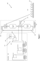
- FIG. 1 shows a schematic diagram of a solar power/thermal system 100 showing the location of a particle heat exchanger 200 according to embodiments of the present invention when located in thermal communication with a solar receiver and thermal storage system 120 of that system.
- the solar power/thermal system 100 comprises four integrated areas:
- the various parts of the solar power/thermal system 100 can have various configurations depending in the application, power requirements and technology used at the solar power/thermal system 100.
- the solar receiver 122 can have a number of different configurations to heat the heat transfer particles therein.
- the present invention concerns the heat exchanger 125 component of the receiver and thermal storage system 120, embodiments of which are illustrated and described in relation to Figures 2 to 4 .
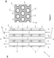
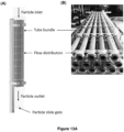
- Figure 2 illustrates a first embodiment of a particle heat exchanger 200 according to the present invention.
- Figure 2 provides a front cross-sectional view ( Figure 2(A) ) and a top cross-sectional view ( Figure 2(B) ) of the particle heat exchanger 200.
- the particle heat exchanger 200 comprises a flow space 210 which encloses a vertical tube array 220 formed a multiple spaced apart heat transfer tubes (or pipes) 222.
- the heat transfer tubes 222 comprise elongate tubes having a required wall thickness, constructed from a heat conductive material, preferably a metal such as stainless steel and nickel-based alloy.
- the heat transfer tubes 222 extend vertically parallel to axis X-X shown in Figure 2 .
- the heat transfer tubes 222 include an internal cavity through which a heat transfer fluid 205 flows.
- the heat transfer fluid 205 also known as working fluid
- particle flow space 210 Surrounding the array of heat transfer tubes 222 is particle flow space 210 containing heat transfer particles. Whilst not shown, the particle flow space 210 is bounded by a housing which comprises a container having an interior space which encloses all of the heat transfer tubes 222 within the interior space therein.
- the heat transfer particles flow from an upper inlet 230 to a lower outlet 232.
- the heat transfer fluid 205 in heat transfer tubes 222 flows in counter-current direction to the flow of heat transfer particles 207.
- the actual heat exchanger 200 is contained within a sealed housing with the inlet and outlets of the heat transfer particles 207 and heat transfer fluid 205 sections connected to appropriately designed fluid and particle feed and outlet headers which would direct the flows in the required directions.
- the particle heat exchanger 200 therefore comprises a counter-flow arrangement of two heat transfer fluids, i.e. a heat transfer fluid 205 inside the heat transfer tubes 222 and a moving bed 236 of heat transfer particles 207 falling under gravity around and along the outer surface of the tubes 222.
- the heat transfer particles 207 comprise any suitable particles having suitable specific heat capacity for the required heating (in the receiver) and heat transfer application.
- the heat transfer particles 207 are typically solid particles or solid particulates having a mean particle size of between 100 and 800 ⁇ m. In exemplary embodiments the solid particulates have a mean particle size of around 300 ⁇ m.
- the inventors have selected ceramic heat transfer particles 207 such as alumina based ceramic particles for testing purposes, comprising a ceramic proppant comprising 75% Al 2 O 3 , 11% SiO 2 , 9% Fe 2 O 3 , and 3% TiO.
- particles/ particulates could equally be used for example sands such as silicon dioxide based granular particulates and/or calcium carbonate granular particulates.
- the invention is not intended to be limited to specific heat transfer particles.
- the heat transfer fluid 205 could comprise any heat transfer liquid, gas, solid or their mixture which is suitable for the particular heat transfer application and conditions.
- steam, nitrogen, carbon dioxide, air or other process gases could be used as the heat transfer fluid.
- the heat transfer fluid 205 could comprise a molten salt.
- each heat transfer tube 222 is sufficiently long, typically greater than 1 m, the particle-side heat transfer coefficient from the heat transfer particle flow to the heat transfer fluid through the wall of the heat transfer tube will approach a constant value even when the velocity of the heat transfer particle flow is increased.
- the inventors consider that this is due to the rapid decrease in the length of the thermal entrance region such that the heat transfer particle flow becomes fully developed thermally. Without mixing, the particle-side heat transfer coefficient can only be improved by narrowing the radial width of the heat transfer particle flow relative to the wall (heat transfer surface) of the heat transfer tube 222, thus ensuring effective heat transfer from all particles from that flow.
- This solution has practical challenges as thermal expansion of the tube 222 may create flow channelling/blocking in such a narrow particle flow.
- the heat transfer particle flow is split into multiple stages to prevent the full thermal development of that flow.
- multiple flow distribution plates 250 (acting as a divider element) are included at spaced apart positions along the length of the vertical tube array 210.
- Each flow distribution plate 250 is designed to split the heat exchanger 200 into a series of short particle beds (S1, S2, S3, S4 and S5 in Figure 2 ) to redistribute the gravity-driven moving particles.
- Each flow distribution plate 250 includes a series of flow constriction openings 260 comprising annular gaps in the plate 250 at the intersection of the flow distribution plate 250 and each heat transfer tube 222. These flow constriction openings 260 comprise annulus shaped gaps, annularly extending around each heat transfer tube 222.
- Each flow constriction openings 260 includes a tube support fingers/ arms 265 ( Figure 2A ) which extend from the distribution plate 250 across the opening 260 to engage the surface of each heat transfer tube 222 to hold the tube array in place within the heat exchanger 200 is a position aligned with axis X-X (i.e. vertically).
- the fingers 265 comprise tabs that which extend from the distribution plate 250 to engage the heat transfer tube 222.
- rods, flanges, ribs or similar protuberances that extend from the distribution plate 250 or from the heat transfer tube 222 could equally be used.
- the fingers 265 are also configured to allow axial thermal expansion of the heat transfer tubes 222 when heated and also maintain consistent particle flow channels between the heat transfer tubes 222.
- the present invention therefore provides an alternate solution to narrowing the width of the particle flow by providing mixing of the heat transfer particle flow at various points along the flow path.
- the present invention resolves such inherent heat transfer barrier limitations associated with long and fast moving bed particles to provide a design pathway towards a more cost-effective commercial scale PHX.
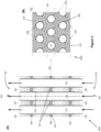
- FIG. 3 provides a front cross-sectional view ( Figure 3(A) ) and a top cross-sectional view ( Figure 3(B) ) of the particle heat exchanger 200A.
- the heat exchanger 200A has largely the same configuration as described for heat exchanger 200 illustrated in Figure 2 .
- Like features have there been provided with the same reference numerals as used in relation to heat exchanger 200 illustrated in Figure 2 .
- the flow distribution plates 250 include fluidising gas arrangements 267 configured to create local particle fluidisation zones in the region of the flow constrictions.
- the flow distribution plates 250 (the divider) therefore serve as the channel to supply fluidisation gas.
- the local particle fluidisation zones further enhance the particle-side heat transfer coefficient.
- the fluidising gas arrangements 267 typically comprise gas injection points, such as nozzles located on the top of the flow distribution plates 250, having a fluid connection to a fluidisation gas inlet 269 at one side of each flow distribution plates 250. This use of fluidising gas arrangements 267 creates bubbling fluidisation in the particle bed at the bottom of selected or all stages in the particle heat exchanger 200A. Bubbling fluidisation allowing particles to mix before entering the next stage to enhance particle-side heat transfer.
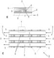
- FIG. 4 provides a front cross-sectional view ( Figure 4(A) ) and a top cross-sectional view ( Figure 4(B) ) of the particle heat exchanger 200B.
- the heat exchanger 200B has largely the same configuration as described for heat exchanger 200 illustrated in Figure 2 .
- Like features have there been provided with the same reference numerals as used in relation to heat exchanger 200 illustrated in Figure 2 .
- the free space of the housing enclosing the heat transfer tubes 222 has been replaced with a plurality of spaced apart containers 270, each enclosing a heat transfer tube 222 therein.
- each spaced apart container 270 is formed from a cylindrical shaft 271 or bore that co-axially encloses each heat transfer tube 222.
- this could equally be provided by a plurality of elongate tubes which extend co-axially around each heat transfer tube 222.
- each stage is formed from a block 272 having a plurality of spaced apart shafts 271.
- a heat transfer tube 222 extends through each spaced apart shaft 271.
- Each shaft 271 having a larger diameter than the outer diameter of the heat transfer tube 222 that extends therethrough, therefore forming an annular gap therebetween.
- the overall heat exchanger includes two or more two stacked blocks 272, allowing each flow distribution plate 250 being located between adjacent stacked blocks 272.
- Each block 272 preferably comprises a high-temperature ceramic blocks with the heat transfer tubes 222 concentrically located inside these the shafts 271 ( Figure 4 ).
- This configuration creates annular gap 260 allowing hot particles to flow through and transfer heat to the heat transfer fluid inside the tubes 222 whereas the previous embodiments allows all the space between tubes 222 to be used as particle flow channel.
- Each flow distribution plate 250 includes a similar flow constriction opening and tube support arms as previously described to enhance mixing at the end of each stage and to ensure consistent annular gap between the inner wall of the shafts 271 and the outer wall of the heat transfer tubes 222.
- the annular flow constriction gap 260 between the plate holes and tubes is designed smaller than the gap between the holes of ceramic block and tubes. This ensures that the particle-side heat transfer coefficient can be enhanced with continuous new thermal entrance regions and re-mixing of particles 207.
- FIG. 5 illustrates an adaption of the arrangements 200 and 200B shown in Figures 2 and 4 .
- the heat exchanger 200C has largely the same configuration as described for heat exchanger 200 illustrated in Figure 2 .
- Like features have there been provided with the same reference numerals as used in relation to heat exchanger 200 illustrated in Figure 2 .
- a radial fin/ protuberance 280 is included on each heat transfer tube 222 before the flow constriction - i.e. longitudinally spaced apart from a divider, in a position before the flow distribution plate (divider) 250 along the length of the heat transfer222 relative to the direction of flow of the heat transfer particles 207.
- This radial fin 280 extends circumferentially around each heat transfer tube 222. The radial fin 280 in this position has been found to enhance the mixing of particles 207 which could create a full renewal of the thermal entrance zone at the subsequent stage below.
- the radial fin 280 interrupts the development of the thermal boundary layer of particles (near wall particles 284 in Figure 5(B) near the heat transfer tube wall 285 (cooler than the bulk particles) and then mix with hot particles in the bulk particle stream 207 prior flowing through the annular gap 287 of the flow distribution plate 250.
- particles 288 near the heat transfer wall 285 at the start of the subsequent stage below can be fully replaced by hot particles resulting in a full renewal of the thermal entrance zone (full mixing of particles 207). This has been found to further enhance the particle side heat transfer coefficient of this arrangement 200C.
- Example 1 Heat transfer analysis - 2D heat transfer model
- Figure 6 shows a heat transfer model of a single tube-in-bed PHX which solves a two-dimensional steady-state conservation energy equation.
- the model was developed to understand particle-side heat transfer and provide a guide for conceptual design.
- the tube-in-bed PHX can be assumed to be a 2D axisymmetric problem instead of a 3D problem.
- the particles are assumed to behave as a single continuous medium moving downwardly under gravity along the outer surface of the tube (heat transfer wall). The heat transfer between a moving particle bed and a heat transfer wall takes place by thermal conduction in the radial direction.
- R nw particlewall contact resistance
- R b thermal resistance governed by effective thermal conduction inside the bulk flow
- ⁇ is the bulk density of particle
- c p is the specific heat capacity of particle
- u p is the particle bed velocity
- T p is the particle temperature
- k eff is the effective thermal conductivity of particles
- r and y are the radial and axial coordinate respectively.
- the left hand side of above equation represents the net enthalpy of the particle flow in the control volume whereas the term on the right hand side represents the effective thermal conduction in the radial direction of the control volume.
- h p 1 1 h nw + 1 h b
- h nw the wall to particle heat transfer coefficient
- h b the heat transfer coefficient due to thermal conduction of the bulk flow.
- the effective thermal conductivity inside the bulk flow is calculated using the Zehner - Schlunder model (Zehner and Schlunder, 1970).
- solid fraction of 0.6 is used for a packed-bed with spherical particles.
- the wall to particle heat transfer coefficient is calculated using the method proposed by Botterill and Denloye (1978). In this example, the effect of radiation heat transfer is not considered.
- Example 2 Heat transfer analysis - Staged moving-bed 2D heat transfer model
- Figure 11 shows a schematic diagram of a staged moving-bed particle heat exchanger connecting in series.
- the PHX is divided into a number of stages ( N stage ) and assumed full mixing of particles at the outlet before entering to the next stage.
- N stage the heat transfer between a moving particle bed and a heat transfer wall is calculated using the methodology mentioned in Example 1 by solving a two-dimensional steady-state conservation energy equation.
- Figure 12 shows a comparison of bulk-to-wall heat transfer coefficient ( h p ) as a function of particle velocity ( u p ) for a single stage PHX, 4 stages PHX and 10 stages PHX.
- the total heat exchanger length ( L hx ) for all three cases is set to be 2 m.
- the results reveal that as the particle velocity ( u p ) increases, a series of shorter PHXs comparing to a single stage PHX enables enhancement of the particle-side heat transfer coefficient through re-mixing of particles at the outlet before entering to the next stage and also allowing to continuously create new thermal entrance regions.
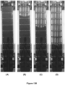
- the experimental rig was tested with particles (300 ⁇ m ceramic proppants comprising 75% Al 2 O 3 , 11% SiO 2 , 9% Fe 2 O 3 , and 3% TiO) packed in the housing and an upper bin. Particles are released from the heat exchanger by opening the slide gate at the bottom of the test rig.
- Figures 13B (A) to (D) show the progress of the top of the particle flow through the cold flow experimental rig from full ( Figure 13B(A) , to 2/3 flow completion ( Figure 13B(D) .
- the experimental trials showed that there were no particles blockage when flowing through the annular gap of the flow distribution plate and no significant particle stagnation zone. Additionally, the experimental trials showed that the presence of flow constriction zones using divider plates did cause the particulate flow to remix at every flow stage when flowing towards and through each flow constriction. Each stage did act as a short particle bed, which gravity fed into the subsequent stage below.
- a hot particle test rig was constructed in accordance with the heat exchanger configuration shown in Figure 2 . As illustrated in Figure 14 , this rig consisted of a hot bin incorporating electric heating elements, a single shell and tube particle heat exchanger, a particle flow control valve and a cold bin (receptacle). Dense particles will firstly be heated to the desired temperature in the hot bin and the hot particles will be released to the shell-side of the heat exchanger by opening the particle flow control valve. Heat will be extracted from the hot particles to the cooling water in the tube and then particles will be released to the receptacle. Temperatures and mass flow rates will be measured throughout the experiments.
- the experimental rig was tested with particles (350 ⁇ m ceramic proppants comprising 75% Al 2 O 3 , 11% SiO 2 , 9% Fe 2 O 3 , and 3% TiO).
- the overall heat transfer coefficient ( U hx ) was calculated using the logarithmic mean temperature difference method for a counter-flow heat exchanger and the water-side convective heat transfer coefficient ( h f ) was calculated using the Gnielinski's equation.
- the hot particle test rig will be used to investigate the particle bulk to wall heat transfer coefficient ( h p ) using the hot particle test rig.
- Experimental results will be used to validate the models developed in Examples 1 to 2 and confirm the particle side heat transfer enhancement for the staged particle heat exchanger design.
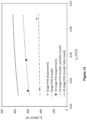
- Figure 15 shows a comparison of measured and simulated particle heat transfer coefficient ( h p ) values over the particle velocity ( u p ) range of interest for a single stage PHX and 10 stages PHX.
- the total heat exchanger length ( L hx ) for both cases is 1 m. It can be seen that h p values obtained from the heat transfer models as developed in Examples 1 and 2 agree well with measurements for both PHXs. In the case of 10 stages PHX, the heat transfer model assumes partial mixing of the particles near the constriction gap for each stage.
- the experimental results also confirm the particle side heat transfer enhancement for the heat exchanger design 200 as illustrated in Figure 2 as compared to the heat exchanger design without multiple staging. Based on the heat transfer model that assumes full mixing of the particles near the constriction gap for each stage, results shown in Figure 15 reveals that the particle side heat transfer could be further enhanced due to full renewal of thermal entrance effects (i.e. full mixing of particles) for each stage.
Landscapes
- Engineering & Computer Science (AREA)
- Mechanical Engineering (AREA)
- General Engineering & Computer Science (AREA)
- Physics & Mathematics (AREA)
- Thermal Sciences (AREA)
- Life Sciences & Earth Sciences (AREA)
- Sustainable Development (AREA)
- Sustainable Energy (AREA)
- Chemical & Material Sciences (AREA)
- Combustion & Propulsion (AREA)
- Heat-Exchange Devices With Radiators And Conduit Assemblies (AREA)
Claims (15)
- Partikelwärmetauscher (200), umfassend:
ein Gehäuse, beinhaltend:einen Einlass (230), der sich an der Oberseite des Gehäuses befindet, undeinen Auslass (232), der sich unterhalb des Einlasses befindet,wobei das Gehäuse konfiguriert ist, um einen Strom von Wärmeübertragungspartikeln (207) einzuschließen, der innerhalb des Gehäuses vom Einlass (230) nach unten zum Auslass (232) strömt;mindestens ein Wärmeübertragungsrohr (222), das ein Wärmeübertragungsmedium beinhaltet, wobei jedes Wärmeübertragungsrohr (222) in dem Gehäuse eingeschlossen ist und mit dem Strom von Wärmeübertragungspartikeln (207) darin in Kontakt steht, wobei sich jedes Wärmeübertragungsrohr (222) im Wesentlichen parallel zu einer Achse erstreckt, die sich zwischen dem Einlass (230) und Auslass (232) des Gehäuses erstreckt; undmindestens eine Trennwand (250), die sich zwischen dem Einlass (230) und Auslass (232) des Gehäuses befindet, wobei sich das mindestens eine Wärmeübertragungsrohr (222) durch jede Trennwand hindurch erstreckt, jede Trennwand (250) mindestens eine Öffnung (260) beinhaltet, die konfiguriert ist, um mindestens eine Strömungseinschränkung im Strom von Wärmeübertragungspartikeln (207) zwischen dem Einlass (230) und Auslass (232) des Gehäuses zu bilden. - Partikelwärmetauscher (200) nach Anspruch 1, wobei das Gehäuse konfiguriert ist, um den Strom von Wärmeübertragungspartikeln (207) im Verhältnis zum Strom zwischen dem Einlass (230) und Auslass (232) des Gehäuses senkrecht nach unten vom Einlass (230) zum Auslass (232) zu lenken.
- Partikelwärmetauscher (200) nach Anspruch 1 oder 2, wobei die Achse zwischen dem Einlass (230) und Auslass (232) eine vertikale Achse definiert und jedes der Wärmeübertragungsrohre (222) innerhalb des Gehäuses vertikal ausgerichtet ist.
- Partikelwärmetauscher (200) nach einem vorstehenden Anspruch, wobei die mindestens eine Öffnung (260) der Trennwand (250) den Strom um mindestens 20% der Strömungsquerschnittsfläche innerhalb des Gehäuses, vorzugsweise zwischen 20% und 80% der Strömungsquerschnittsfläche innerhalb des Gehäuses einschränkt.
- Partikelwärmetauscher (200) nach einem vorstehenden Anspruch, wobei die Öffnung (260) eine Blende umfasst, die sich in der Nähe des Schnittpunkts zwischen jedem der Wärmeübertragungsrohre (222) und jeder Trennwand (250) befindet und diese vorzugsweise umgibt.
- Partikelwärmetauscher (200) nach einem vorstehenden Anspruch, wobei die Öffnung (260) eine ringförmige Öffnung, vorzugsweise einen Ringraum umfasst, der/die den Schnittpunkt zwischen jedem der Wärmeübertragungsrohre (222) und jeder Trennwand (250) umgibt.
- Partikelwärmetauscher (200) nach einem vorstehenden Anspruch, wobei jede Öffnung (260) mindestens einen Arm (265) beinhaltet, der sich von der Trennwand (250) zum Wärmeübertragungsrohr (222) erstreckt und konfiguriert ist, um das Wärmeübertragungsrohr (222) in jeder Öffnung (260) zu lokalisieren.
- Partikelwärmetauscher (200) nach einem vorstehenden Anspruch, wobei das mindestens eine Wärmeübertragungsmedium ein Wärmeübertragungsfluid (205) umfasst, das durch jedes Wärmeübertragungsrohr (222) hindurch strömt, und der Strom von Wärmeübertragungsfluid (205) in mindestens einem von Gegenstrom oder Gleichstrom zum Strom von Wärmeübertragungspartikeln (207) verläuft.
- Partikelwärmetauscher (200) nach einem vorstehenden Anspruch, der mindestens zwei Wärmeübertragungsrohre (222), vorzugsweise mehrere Wärmeübertragungsrohre (222), umfasst, die innerhalb des Gehäuses seitlich beabstandet sind.
- Partikelwärmetauscher (200) nach einem vorstehenden Anspruch, wobei der Partikelwärmetauscher (200) mindestens zwei Trennwände (250) beinhaltet, die zwischen dem Einlass (230) und Auslass (232) des Gehäuses entlang der Länge jedes Wärmeübertragungsrohrs (222) beabstandet sind.
- Partikelwärmetauscher (200) nach einem vorstehenden Anspruch, wobei die mindestens eine Trennwand (250) ein planares Element umfasst, das radial zu der sich zwischen dem Einlass (230) und Auslass (232) erstreckenden Achse ausgerichtet ist, um das Gehäuse in mindestens zwei getrennte Partikelstromkammern zu unterteilen, wobei die Trennwand (250) vorzugsweise ein Blech oder eine Platte umfasst.
- Partikelwärmetauscher (200) nach einem vorstehenden Anspruch, wobei das Gehäuse umfasst:
einen Behälter, der einen Innenraum aufweist, der alle Wärmeübertragungsrohre (222) im Innenraum darin einschließt;
eine Vielzahl voneinander beabstandeter Strömungskanäle, die jeweils einen Einlass und Auslass aufweisen und jeweils ein Wärmeübertragungsrohr (222) enthalten, das sich darin erstreckt; oder
eine Vielzahl voneinander beabstandeter Behälter (270), die jeweils ein Wärmeübertragungsrohr darin einschließen. - Partikelwärmetauscher (200) nach Anspruch 12, wobei das Gehäuse einen Montagekörper (272) beinhaltet, der eine Vielzahl beabstandeter Wellen (271) aufweist, sich ein Wärmeübertragungsrohr (222) durch jede beabstandete Welle (271) hindurch erstreckt, wobei jede Welle (271) einen größeren Durchmesser aufweist als der Außendurchmesser des Wärmeübertragungsrohrs (222), das sich durch sie erstreckt.
- Partikelwärmetauscher (200) nach einem vorstehenden Anspruch, der weiter mindestens eine Fluidisierungsgasanordnung beinhaltet, die sich an oder in der Nähe der Verengung befindet, die konfiguriert ist, um in der Nähe der Verengung eine lokalisierte Fluidisierungspartikelblase zu erzeugen.
- Partikelwärmetauscher (200) nach einem vorstehenden Anspruch, der weiter mindestens einen spiralförmigen Einsatz beinhaltet, der sich um mindestens ein Wärmeübertragungsrohr (222) erstreckt, und/oder mindestens ein radiales Element, vorzugsweise eine Rippe oder Lamelle (280), das sich radial von der Oberfläche mindestens eines Wärmeübertragungsrohres (222) in das Gehäuse erstreckt.
Applications Claiming Priority (2)
| Application Number | Priority Date | Filing Date | Title |
|---|---|---|---|
| AU2019903064A AU2019903064A0 (en) | 2019-08-22 | Moving-bed particle heat exchanger | |
| PCT/AU2020/050874 WO2021030875A1 (en) | 2019-08-22 | 2020-08-21 | Moving-bed particle heat exchanger |
Publications (3)
| Publication Number | Publication Date |
|---|---|
| EP4018145A1 EP4018145A1 (de) | 2022-06-29 |
| EP4018145A4 EP4018145A4 (de) | 2023-09-13 |
| EP4018145B1 true EP4018145B1 (de) | 2025-05-21 |
Family
ID=74659529
Family Applications (1)
| Application Number | Title | Priority Date | Filing Date |
|---|---|---|---|
| EP20853642.5A Active EP4018145B1 (de) | 2019-08-22 | 2020-08-21 | Partikelwärmetauscher mit wanderbett |
Country Status (10)
| Country | Link |
|---|---|
| US (1) | US12196495B2 (de) |
| EP (1) | EP4018145B1 (de) |
| CN (1) | CN114270126A (de) |
| AU (1) | AU2020332175A1 (de) |
| CL (1) | CL2022000407A1 (de) |
| DK (1) | DK4018145T3 (de) |
| ES (1) | ES3038099T3 (de) |
| FI (1) | FI4018145T3 (de) |
| MA (1) | MA55833B1 (de) |
| WO (1) | WO2021030875A1 (de) |
Families Citing this family (6)
| Publication number | Priority date | Publication date | Assignee | Title |
|---|---|---|---|---|
| EP4105479B1 (de) | 2021-06-15 | 2025-05-14 | John Cockerill Renewables S.A. | Partikelwärmetauscher für ein solarturmkraftwerk |
| CN113375347B (zh) * | 2021-07-13 | 2023-01-06 | 西安热工研究院有限公司 | 一种蜂窝状颗粒换热器及储热发电系统 |
| US20240003532A1 (en) * | 2022-07-01 | 2024-01-04 | The Babcock & Wilcox Company | Green steam industrial steam generator process and system |
| TWI812429B (zh) * | 2022-08-25 | 2023-08-11 | 亞東學校財團法人亞東科技大學 | 具有廢熱發電裝置的移動顆粒床 |
| CN116085086A (zh) * | 2022-11-28 | 2023-05-09 | 中国科学院工程热物理研究所 | 基于固体颗粒储放热的二氧化碳雷顿循环热电联产系统 |
| CN115979046B (zh) * | 2022-12-28 | 2026-03-03 | 西安交通大学 | 一种移动床换热器及其定向调控扰流强化换热方法 |
Family Cites Families (30)
| Publication number | Priority date | Publication date | Assignee | Title |
|---|---|---|---|---|
| US1454053A (en) * | 1920-02-18 | 1923-05-08 | Griscom Russell Co | Oil cooler |
| US2995426A (en) * | 1956-12-04 | 1961-08-08 | Hydrocarbon Research Inc | Elevated fluidizing reactor |
| FR1288835A (fr) * | 1961-02-14 | 1962-03-30 | Procédé d'échange de chaleur par surface entre fluides d'une part et matières granuleuses ou pulvérulentes d'autre part | |
| US3663179A (en) * | 1970-04-20 | 1972-05-16 | Chemical Construction Corp | Apparatus for exothermic catalytic reactions |
| GB1395900A (en) * | 1971-10-14 | 1975-05-29 | Technical Dev Capital Ltd | Fluidized bed heat exchangers |
| US3982901A (en) * | 1975-06-25 | 1976-09-28 | Dorr-Oliver Incorporated | Heat transfer element and tuyere for fluidized bed reactor |
| US4307773A (en) * | 1978-08-28 | 1981-12-29 | Smith Richard D | Fluid bed heat exchanger for contaminated gas |
| US4313301A (en) * | 1979-10-25 | 1982-02-02 | Caterpillar Tractor Co. | Rotating fluidized bed heat exchanger |
| GB2116686B (en) * | 1982-02-18 | 1985-01-30 | Tokyo Shibaura Electric Co | Heat exchangers installed in fluidized beds |
| US4479308A (en) * | 1982-03-30 | 1984-10-30 | Chevron Research Company | Process and device for recovering heat from a particulate solid |
| DE3214958C2 (de) * | 1982-04-22 | 1986-10-30 | L. & C. Steinmüller GmbH, 5270 Gummersbach | Regenerativer Gas-Gas-Wärmetauscher in Kolonnenbauweise mit wärmeübertragenden Elementen als Wirbelschicht |
| US4482358A (en) * | 1983-03-17 | 1984-11-13 | General Electric Company | Granular bed filtering device |
| US4651807A (en) * | 1985-03-13 | 1987-03-24 | Westinghouse Electric Corp. | Method and apparatus for cooling a high temperature waste gas using a jetting bed, fluidized bed technique |
| FR2581173B1 (fr) * | 1985-04-24 | 1989-03-31 | Charbonnages De France | Echangeur a lit fluidise pour transfert de chaleur |
| US4735780A (en) * | 1986-07-15 | 1988-04-05 | The M. W. Kellogg Company | Ammonia synthesis converter |
| DE68928556T2 (de) * | 1988-11-02 | 1998-04-30 | Colortronic Co | Lufttrockner mit Adsorptionsmittel |
| US4969937A (en) * | 1989-05-30 | 1990-11-13 | Electric Power Research Institute | Vertically tiered particle filtering apparatus |
| US5141047A (en) * | 1991-03-01 | 1992-08-25 | Riley Stoker Corporation | Fluidized bed heat exchanger |
| NL9300666A (nl) * | 1993-04-20 | 1994-11-16 | Bronswerk Heat Transfer Bv | Inrichting voor het uitvoeren van een fysisch en/of chemisch proces, zoals een warmtewisselaar. |
| US5832991A (en) * | 1995-12-29 | 1998-11-10 | Cesaroni; Joseph Anthony | Tube and shell heat exchanger with baffle |
| AUPO663297A0 (en) * | 1997-05-07 | 1997-05-29 | Technological Resources Pty Limited | Enhanced heat transfer |
| TWI255734B (en) * | 2004-03-30 | 2006-06-01 | Ind Tech Res Inst | Thermal regenerative granular-moving bed apparatus |
| EP1600209B1 (de) * | 2004-05-29 | 2024-08-21 | Topsoe A/S | Reaktor mit Wärmetausch |
| FR2966567B1 (fr) | 2010-10-20 | 2014-11-14 | Centre Nat Rech Scient | Dispositif collecteur d'energie solaire |
| US9464847B2 (en) * | 2011-02-04 | 2016-10-11 | Lockheed Martin Corporation | Shell-and-tube heat exchangers with foam heat transfer units |
| US9513059B2 (en) * | 2011-02-04 | 2016-12-06 | Lockheed Martin Corporation | Radial-flow heat exchanger with foam heat exchange fins |
| US20130312946A1 (en) * | 2012-05-24 | 2013-11-28 | Kellogg Brown & Root Llc | Methods and Systems for Cooling Hot Particulates |
| EP2884162A1 (de) * | 2013-12-16 | 2015-06-17 | Doosan Lentjes GmbH | Wirbelbett-Wärmetauscher |
| AT518186B1 (de) | 2016-06-10 | 2017-08-15 | Univ Wien Tech | Wärmekraftwerk und Verfahren zum Speichern von Wärme |
| US10488120B2 (en) * | 2017-02-16 | 2019-11-26 | Gas Technology Institute | Air cooling day cycle-based processing and systems |
-
2020
- 2020-08-21 EP EP20853642.5A patent/EP4018145B1/de active Active
- 2020-08-21 MA MA55833A patent/MA55833B1/fr unknown
- 2020-08-21 CN CN202080059120.2A patent/CN114270126A/zh active Pending
- 2020-08-21 DK DK20853642.5T patent/DK4018145T3/da active
- 2020-08-21 US US17/637,207 patent/US12196495B2/en active Active
- 2020-08-21 ES ES20853642T patent/ES3038099T3/es active Active
- 2020-08-21 FI FIEP20853642.5T patent/FI4018145T3/fi active
- 2020-08-21 WO PCT/AU2020/050874 patent/WO2021030875A1/en not_active Ceased
- 2020-08-21 AU AU2020332175A patent/AU2020332175A1/en active Pending
-
2022
- 2022-02-21 CL CL2022000407A patent/CL2022000407A1/es unknown
Also Published As
| Publication number | Publication date |
|---|---|
| MA55833B1 (fr) | 2023-01-31 |
| MA55833A1 (fr) | 2022-07-29 |
| CN114270126A (zh) | 2022-04-01 |
| FI4018145T3 (fi) | 2025-08-22 |
| WO2021030875A1 (en) | 2021-02-25 |
| US20220299270A1 (en) | 2022-09-22 |
| CL2022000407A1 (es) | 2022-09-20 |
| DK4018145T3 (da) | 2025-08-18 |
| ES3038099T3 (en) | 2025-10-09 |
| EP4018145A4 (de) | 2023-09-13 |
| US12196495B2 (en) | 2025-01-14 |
| EP4018145A1 (de) | 2022-06-29 |
| AU2020332175A1 (en) | 2022-04-07 |
Similar Documents
| Publication | Publication Date | Title |
|---|---|---|
| EP4018145B1 (de) | Partikelwärmetauscher mit wanderbett | |
| Hosseinnezhad et al. | Numerical study of turbulent nanofluid heat transfer in a tubular heat exchanger with twin twisted-tape inserts | |
| Zhang et al. | Buoyancy effects on coupled heat transfer of supercritical pressure CO2 in horizontal semicircular channels | |
| Pitie et al. | Circulating fluidized bed heat recovery/storage and its potential to use coated phase-change-material (PCM) particles | |
| Yang et al. | Molten-salt thermal energy storage in thermoclines under different environmental boundary conditions | |
| Bhutta et al. | CFD applications in various heat exchangers design: A review | |
| Too et al. | Development of a staged particle heat exchanger for particle thermal energy storage systems | |
| Ma et al. | Fluidized-bed heat transfer modeling for the development of particle/supercritical-CO2 heat exchanger | |
| Hansjosten et al. | Custom-designed 3D-printed metallic fluid guiding elements for enhanced heat transfer at low pressure drop | |
| Mandal et al. | Heat transfer characteristics of lithium titanate particles in gas-solid packed fluidized beds | |
| Lee et al. | Heat transfer in a pulsating turbulent fluidized bed | |
| CN104841339A (zh) | 一种用于合成气制乙二醇工艺的新型加氢反应器 | |
| US3075580A (en) | Heat exchanger and method | |
| Mirvakili et al. | Two-dimensional mathematical modeling of an industrial ammonia synthesis reactor with CFD analysis | |
| Liu et al. | CFD simulation study of the effect of baffles on the fluidized bed for hydrogenation of silicon tetrachloride | |
| Staub | Solids circulation in turbulent fluidized beds and heat transfer to immersed tube banks | |
| Wang et al. | Visualized study on specific points on demand curves and flow patterns in a single-side heated narrow rectangular channel | |
| Sulzgruber et al. | Numerical investigation on the flow behavior of a novel fluidization based particle thermal energy storage (FP-TES) | |
| Kaur et al. | Granular flow in novel octet shape–based lattice frame material | |
| Jiang et al. | Flow boiling in a downflow circulating fluidized bed evaporator | |
| Qi et al. | Parametric study of particle distribution in tube bundle heat exchanger | |
| Cheng et al. | Numerical simulations and experiments on heat transfer around a probe in the downer reactor for coal gasification | |
| Liu et al. | Numerical simulation of sub-cooled boiling flow with fouling deposited inside channels | |
| Raza et al. | Influence of solid cylinders on fluid flow and thermal analysis in a curved channel with constant magnetic field | |
| Correia et al. | Fluid dynamics performance of phase change material particles in a Wurster spout–fluid bed |
Legal Events
| Date | Code | Title | Description |
|---|---|---|---|
| STAA | Information on the status of an ep patent application or granted ep patent |
Free format text: STATUS: THE INTERNATIONAL PUBLICATION HAS BEEN MADE |
|
| PUAI | Public reference made under article 153(3) epc to a published international application that has entered the european phase |
Free format text: ORIGINAL CODE: 0009012 |
|
| STAA | Information on the status of an ep patent application or granted ep patent |
Free format text: STATUS: REQUEST FOR EXAMINATION WAS MADE |
|
| 17P | Request for examination filed |
Effective date: 20220322 |
|
| AK | Designated contracting states |
Kind code of ref document: A1 Designated state(s): AL AT BE BG CH CY CZ DE DK EE ES FI FR GB GR HR HU IE IS IT LI LT LU LV MC MK MT NL NO PL PT RO RS SE SI SK SM TR |
|
| DAV | Request for validation of the european patent (deleted) | ||
| DAX | Request for extension of the european patent (deleted) | ||
| P01 | Opt-out of the competence of the unified patent court (upc) registered |
Effective date: 20230525 |
|
| A4 | Supplementary search report drawn up and despatched |
Effective date: 20230810 |
|
| RIC1 | Information provided on ipc code assigned before grant |
Ipc: F28D 20/00 20060101ALI20230804BHEP Ipc: F24S 90/00 20180101ALI20230804BHEP Ipc: F24S 80/20 20180101ALI20230804BHEP Ipc: F24S 60/00 20180101ALI20230804BHEP Ipc: F28D 13/00 20060101ALI20230804BHEP Ipc: F28D 7/16 20060101ALI20230804BHEP Ipc: F28D 19/02 20060101ALI20230804BHEP Ipc: F28C 3/16 20060101AFI20230804BHEP |
|
| STAA | Information on the status of an ep patent application or granted ep patent |
Free format text: STATUS: EXAMINATION IS IN PROGRESS |
|
| 17Q | First examination report despatched |
Effective date: 20240419 |
|
| GRAP | Despatch of communication of intention to grant a patent |
Free format text: ORIGINAL CODE: EPIDOSNIGR1 |
|
| STAA | Information on the status of an ep patent application or granted ep patent |
Free format text: STATUS: GRANT OF PATENT IS INTENDED |
|
| INTG | Intention to grant announced |
Effective date: 20241217 |
|
| GRAS | Grant fee paid |
Free format text: ORIGINAL CODE: EPIDOSNIGR3 |
|
| GRAA | (expected) grant |
Free format text: ORIGINAL CODE: 0009210 |
|
| STAA | Information on the status of an ep patent application or granted ep patent |
Free format text: STATUS: THE PATENT HAS BEEN GRANTED |
|
| AK | Designated contracting states |
Kind code of ref document: B1 Designated state(s): AL AT BE BG CH CY CZ DE DK EE ES FI FR GB GR HR HU IE IS IT LI LT LU LV MC MK MT NL NO PL PT RO RS SE SI SK SM TR |
|
| REG | Reference to a national code |
Ref country code: GB Ref legal event code: FG4D |
|
| REG | Reference to a national code |
Ref country code: CH Ref legal event code: EP |
|
| REG | Reference to a national code |
Ref country code: DE Ref legal event code: R096 Ref document number: 602020051781 Country of ref document: DE |
|
| REG | Reference to a national code |
Ref country code: IE Ref legal event code: FG4D |
|
| REG | Reference to a national code |
Ref country code: DK Ref legal event code: T3 Effective date: 20250808 |
|
| REG | Reference to a national code |
Ref country code: FI Ref legal event code: FGE |
|
| REG | Reference to a national code |
Ref country code: SE Ref legal event code: TRGR |
|
| REG | Reference to a national code |
Ref country code: NL Ref legal event code: FP |
|
| PGFP | Annual fee paid to national office [announced via postgrant information from national office to epo] |
Ref country code: NL Payment date: 20250808 Year of fee payment: 6 |
|
| PG25 | Lapsed in a contracting state [announced via postgrant information from national office to epo] |
Ref country code: PT Free format text: LAPSE BECAUSE OF FAILURE TO SUBMIT A TRANSLATION OF THE DESCRIPTION OR TO PAY THE FEE WITHIN THE PRESCRIBED TIME-LIMIT Effective date: 20250922 |
|
| PGFP | Annual fee paid to national office [announced via postgrant information from national office to epo] |
Ref country code: ES Payment date: 20250904 Year of fee payment: 6 Ref country code: FI Payment date: 20250820 Year of fee payment: 6 |
|
| REG | Reference to a national code |
Ref country code: ES Ref legal event code: FG2A Ref document number: 3038099 Country of ref document: ES Kind code of ref document: T3 Effective date: 20251009 |
|
| PGFP | Annual fee paid to national office [announced via postgrant information from national office to epo] |
Ref country code: DK Payment date: 20250807 Year of fee payment: 6 Ref country code: DE Payment date: 20250811 Year of fee payment: 6 |
|
| REG | Reference to a national code |
Ref country code: LT Ref legal event code: MG9D |
|
| PG25 | Lapsed in a contracting state [announced via postgrant information from national office to epo] |
Ref country code: GR Free format text: LAPSE BECAUSE OF FAILURE TO SUBMIT A TRANSLATION OF THE DESCRIPTION OR TO PAY THE FEE WITHIN THE PRESCRIBED TIME-LIMIT Effective date: 20250822 |
|
| PGFP | Annual fee paid to national office [announced via postgrant information from national office to epo] |
Ref country code: NO Payment date: 20250826 Year of fee payment: 6 |
|
| PG25 | Lapsed in a contracting state [announced via postgrant information from national office to epo] |
Ref country code: PL Free format text: LAPSE BECAUSE OF FAILURE TO SUBMIT A TRANSLATION OF THE DESCRIPTION OR TO PAY THE FEE WITHIN THE PRESCRIBED TIME-LIMIT Effective date: 20250521 |
|
| PGFP | Annual fee paid to national office [announced via postgrant information from national office to epo] |
Ref country code: IT Payment date: 20250827 Year of fee payment: 6 |
|
| PG25 | Lapsed in a contracting state [announced via postgrant information from national office to epo] |
Ref country code: BG Free format text: LAPSE BECAUSE OF FAILURE TO SUBMIT A TRANSLATION OF THE DESCRIPTION OR TO PAY THE FEE WITHIN THE PRESCRIBED TIME-LIMIT Effective date: 20250521 |
|
| PGFP | Annual fee paid to national office [announced via postgrant information from national office to epo] |
Ref country code: GB Payment date: 20250915 Year of fee payment: 6 |
|
| PG25 | Lapsed in a contracting state [announced via postgrant information from national office to epo] |
Ref country code: HR Free format text: LAPSE BECAUSE OF FAILURE TO SUBMIT A TRANSLATION OF THE DESCRIPTION OR TO PAY THE FEE WITHIN THE PRESCRIBED TIME-LIMIT Effective date: 20250521 |
|
| PGFP | Annual fee paid to national office [announced via postgrant information from national office to epo] |
Ref country code: FR Payment date: 20250814 Year of fee payment: 6 |
|
| PGFP | Annual fee paid to national office [announced via postgrant information from national office to epo] |
Ref country code: SE Payment date: 20250829 Year of fee payment: 6 |
|
| PG25 | Lapsed in a contracting state [announced via postgrant information from national office to epo] |
Ref country code: RS Free format text: LAPSE BECAUSE OF FAILURE TO SUBMIT A TRANSLATION OF THE DESCRIPTION OR TO PAY THE FEE WITHIN THE PRESCRIBED TIME-LIMIT Effective date: 20250821 |
|
| PG25 | Lapsed in a contracting state [announced via postgrant information from national office to epo] |
Ref country code: IS Free format text: LAPSE BECAUSE OF FAILURE TO SUBMIT A TRANSLATION OF THE DESCRIPTION OR TO PAY THE FEE WITHIN THE PRESCRIBED TIME-LIMIT Effective date: 20250921 |
|
| PG25 | Lapsed in a contracting state [announced via postgrant information from national office to epo] |
Ref country code: LV Free format text: LAPSE BECAUSE OF FAILURE TO SUBMIT A TRANSLATION OF THE DESCRIPTION OR TO PAY THE FEE WITHIN THE PRESCRIBED TIME-LIMIT Effective date: 20250521 |
|
| REG | Reference to a national code |
Ref country code: AT Ref legal event code: MK05 Ref document number: 1797058 Country of ref document: AT Kind code of ref document: T Effective date: 20250521 |
|
| PG25 | Lapsed in a contracting state [announced via postgrant information from national office to epo] |
Ref country code: AT Free format text: LAPSE BECAUSE OF FAILURE TO SUBMIT A TRANSLATION OF THE DESCRIPTION OR TO PAY THE FEE WITHIN THE PRESCRIBED TIME-LIMIT Effective date: 20250521 Ref country code: SM Free format text: LAPSE BECAUSE OF FAILURE TO SUBMIT A TRANSLATION OF THE DESCRIPTION OR TO PAY THE FEE WITHIN THE PRESCRIBED TIME-LIMIT Effective date: 20250521 |
|
| PG25 | Lapsed in a contracting state [announced via postgrant information from national office to epo] |
Ref country code: CZ Free format text: LAPSE BECAUSE OF FAILURE TO SUBMIT A TRANSLATION OF THE DESCRIPTION OR TO PAY THE FEE WITHIN THE PRESCRIBED TIME-LIMIT Effective date: 20250521 |
|
| PG25 | Lapsed in a contracting state [announced via postgrant information from national office to epo] |
Ref country code: EE Free format text: LAPSE BECAUSE OF FAILURE TO SUBMIT A TRANSLATION OF THE DESCRIPTION OR TO PAY THE FEE WITHIN THE PRESCRIBED TIME-LIMIT Effective date: 20250521 |
|
| PG25 | Lapsed in a contracting state [announced via postgrant information from national office to epo] |
Ref country code: RO Free format text: LAPSE BECAUSE OF FAILURE TO SUBMIT A TRANSLATION OF THE DESCRIPTION OR TO PAY THE FEE WITHIN THE PRESCRIBED TIME-LIMIT Effective date: 20250521 Ref country code: SK Free format text: LAPSE BECAUSE OF FAILURE TO SUBMIT A TRANSLATION OF THE DESCRIPTION OR TO PAY THE FEE WITHIN THE PRESCRIBED TIME-LIMIT Effective date: 20250521 |
|
| REG | Reference to a national code |
Ref country code: CH Ref legal event code: H13 Free format text: ST27 STATUS EVENT CODE: U-0-0-H10-H13 (AS PROVIDED BY THE NATIONAL OFFICE) Effective date: 20260324 |
|
| PLBE | No opposition filed within time limit |
Free format text: ORIGINAL CODE: 0009261 |
|
| STAA | Information on the status of an ep patent application or granted ep patent |
Free format text: STATUS: NO OPPOSITION FILED WITHIN TIME LIMIT |