EP4017765B1 - Dachmodul zur bildung eines fahrzeugdachs mit trägermodul - Google Patents
Dachmodul zur bildung eines fahrzeugdachs mit trägermodul Download PDFInfo
- Publication number
- EP4017765B1 EP4017765B1 EP20764304.0A EP20764304A EP4017765B1 EP 4017765 B1 EP4017765 B1 EP 4017765B1 EP 20764304 A EP20764304 A EP 20764304A EP 4017765 B1 EP4017765 B1 EP 4017765B1
- Authority
- EP
- European Patent Office
- Prior art keywords
- roof
- module
- roof module
- module according
- vehicle
- Prior art date
- Legal status (The legal status is an assumption and is not a legal conclusion. Google has not performed a legal analysis and makes no representation as to the accuracy of the status listed.)
- Active
Links
Images



Classifications
-
- B—PERFORMING OPERATIONS; TRANSPORTING
- B60—VEHICLES IN GENERAL
- B60R—VEHICLES, VEHICLE FITTINGS, OR VEHICLE PARTS, NOT OTHERWISE PROVIDED FOR
- B60R11/00—Arrangements for holding or mounting articles, not otherwise provided for
- B60R11/04—Mounting of cameras operative during drive; Arrangement of controls thereof relative to the vehicle
-
- B—PERFORMING OPERATIONS; TRANSPORTING
- B62—LAND VEHICLES FOR TRAVELLING OTHERWISE THAN ON RAILS
- B62D—MOTOR VEHICLES; TRAILERS
- B62D25/00—Superstructure or monocoque structure sub-units; Parts or details thereof not otherwise provided for
- B62D25/06—Fixed roofs
-
- G—PHYSICS
- G01—MEASURING; TESTING
- G01S—RADIO DIRECTION-FINDING; RADIO NAVIGATION; DETERMINING DISTANCE OR VELOCITY BY USE OF RADIO WAVES; LOCATING OR PRESENCE-DETECTING BY USE OF THE REFLECTION OR RERADIATION OF RADIO WAVES; ANALOGOUS ARRANGEMENTS USING OTHER WAVES
- G01S13/00—Systems using the reflection or reradiation of radio waves, e.g. radar systems; Analogous systems using reflection or reradiation of waves whose nature or wavelength is irrelevant or unspecified
- G01S13/88—Radar or analogous systems specially adapted for specific applications
- G01S13/93—Radar or analogous systems specially adapted for specific applications for anti-collision purposes
- G01S13/931—Radar or analogous systems specially adapted for specific applications for anti-collision purposes of land vehicles
-
- G—PHYSICS
- G01—MEASURING; TESTING
- G01S—RADIO DIRECTION-FINDING; RADIO NAVIGATION; DETERMINING DISTANCE OR VELOCITY BY USE OF RADIO WAVES; LOCATING OR PRESENCE-DETECTING BY USE OF THE REFLECTION OR RERADIATION OF RADIO WAVES; ANALOGOUS ARRANGEMENTS USING OTHER WAVES
- G01S17/00—Systems using the reflection or reradiation of electromagnetic waves other than radio waves, e.g. lidar systems
- G01S17/88—Lidar systems specially adapted for specific applications
- G01S17/93—Lidar systems specially adapted for specific applications for anti-collision purposes
- G01S17/931—Lidar systems specially adapted for specific applications for anti-collision purposes of land vehicles
-
- B—PERFORMING OPERATIONS; TRANSPORTING
- B60—VEHICLES IN GENERAL
- B60R—VEHICLES, VEHICLE FITTINGS, OR VEHICLE PARTS, NOT OTHERWISE PROVIDED FOR
- B60R11/00—Arrangements for holding or mounting articles, not otherwise provided for
- B60R2011/0001—Arrangements for holding or mounting articles, not otherwise provided for characterised by position
- B60R2011/004—Arrangements for holding or mounting articles, not otherwise provided for characterised by position outside the vehicle
-
- G—PHYSICS
- G01—MEASURING; TESTING
- G01S—RADIO DIRECTION-FINDING; RADIO NAVIGATION; DETERMINING DISTANCE OR VELOCITY BY USE OF RADIO WAVES; LOCATING OR PRESENCE-DETECTING BY USE OF THE REFLECTION OR RERADIATION OF RADIO WAVES; ANALOGOUS ARRANGEMENTS USING OTHER WAVES
- G01S13/00—Systems using the reflection or reradiation of radio waves, e.g. radar systems; Analogous systems using reflection or reradiation of waves whose nature or wavelength is irrelevant or unspecified
- G01S13/88—Radar or analogous systems specially adapted for specific applications
- G01S13/93—Radar or analogous systems specially adapted for specific applications for anti-collision purposes
- G01S13/931—Radar or analogous systems specially adapted for specific applications for anti-collision purposes of land vehicles
- G01S2013/9327—Sensor installation details
-
- G—PHYSICS
- G01—MEASURING; TESTING
- G01S—RADIO DIRECTION-FINDING; RADIO NAVIGATION; DETERMINING DISTANCE OR VELOCITY BY USE OF RADIO WAVES; LOCATING OR PRESENCE-DETECTING BY USE OF THE REFLECTION OR RERADIATION OF RADIO WAVES; ANALOGOUS ARRANGEMENTS USING OTHER WAVES
- G01S13/00—Systems using the reflection or reradiation of radio waves, e.g. radar systems; Analogous systems using reflection or reradiation of waves whose nature or wavelength is irrelevant or unspecified
- G01S13/88—Radar or analogous systems specially adapted for specific applications
- G01S13/93—Radar or analogous systems specially adapted for specific applications for anti-collision purposes
- G01S13/931—Radar or analogous systems specially adapted for specific applications for anti-collision purposes of land vehicles
- G01S2013/9327—Sensor installation details
- G01S2013/93273—Sensor installation details on the top of the vehicles
-
- G—PHYSICS
- G01—MEASURING; TESTING
- G01S—RADIO DIRECTION-FINDING; RADIO NAVIGATION; DETERMINING DISTANCE OR VELOCITY BY USE OF RADIO WAVES; LOCATING OR PRESENCE-DETECTING BY USE OF THE REFLECTION OR RERADIATION OF RADIO WAVES; ANALOGOUS ARRANGEMENTS USING OTHER WAVES
- G01S7/00—Details of systems according to groups G01S13/00, G01S15/00, G01S17/00
- G01S7/02—Details of systems according to groups G01S13/00, G01S15/00, G01S17/00 of systems according to group G01S13/00
- G01S7/027—Constructional details of housings, e.g. form, type, material or ruggedness
-
- G—PHYSICS
- G01—MEASURING; TESTING
- G01S—RADIO DIRECTION-FINDING; RADIO NAVIGATION; DETERMINING DISTANCE OR VELOCITY BY USE OF RADIO WAVES; LOCATING OR PRESENCE-DETECTING BY USE OF THE REFLECTION OR RERADIATION OF RADIO WAVES; ANALOGOUS ARRANGEMENTS USING OTHER WAVES
- G01S7/00—Details of systems according to groups G01S13/00, G01S15/00, G01S17/00
- G01S7/48—Details of systems according to groups G01S13/00, G01S15/00, G01S17/00 of systems according to group G01S17/00
- G01S7/481—Constructional features, e.g. arrangements of optical elements
- G01S7/4811—Constructional features, e.g. arrangements of optical elements common to transmitter and receiver
- G01S7/4813—Housing arrangements
Definitions
- the invention relates to a roof module for forming a vehicle roof on a motor vehicle according to the preamble of claim 1.
- roof modules are widely used in vehicle construction because these roof modules can be prefabricated as separate functional modules and delivered to the assembly line when the vehicle is assembled.
- the roof module can either be part of a rigid vehicle roof or part of an openable roof assembly.
- Autonomous or semi-autonomous vehicles are becoming increasingly common in vehicle construction.
- a large number of environmental sensors are required that record the vehicle's surroundings and use them to determine the current traffic situation.
- the known environmental sensors send or receive corresponding electromagnetic signals, for example laser beams or radar beams, whereby a data model of the vehicle's surroundings can be generated by evaluating the corresponding signals.
- the known environmental sensors are installed in a corresponding sensor housing.
- This sensor housing is attached to the top of the vehicle roof in order to provide the environmental sensor with the highest possible observation position.
- the disadvantage of attaching the environmental sensor together with a sensor housing on the vehicle roof is that this adversely affects both the aerodynamic properties and the design of the vehicle.
- the fastening of the sensor housing to the vehicle roof requires a very high level of precision in order to ensure the functionality of the environmental sensors when detecting the vehicle's surroundings. The high-precision fixing of the sensor housing to the vehicle roof is therefore time-consuming and costly.
- Printed matter EP 3 514 487 A1 discloses a sensor system for a motor vehicle, comprising a lidar sensor.
- Printed matter EN 10 2017 104 988 A1 shows a roof sensor of a vehicle that has a column-like housing.
- the object of the present invention is therefore to propose a new roof module which avoids the disadvantages of the previously known prior art described above.
- the environment sensor is attached under the roof skin.
- a carrier module is used to attach the environment sensor to the roof module below the roof skin. Pre-assembling the environment sensor on the carrier module ensures that the environment sensor is positioned precisely without any problems.
- installing the environment sensors in the roof module is made considerably easier, since all that is required is to attach the carrier module with the environment sensor pre-assembled on it to the roof module. This eliminates the need for individual adjustment of the environment sensor in the roof module. Instead, only the carrier module needs to be precisely aligned in the roof module. In the event of a malfunction, the entire carrier module with the environment sensor attached to it can be easily dismantled and replaced if necessary.
- the carrier module Preferably, several environmental sensors can be mounted together on the carrier module.
- the environmental sensors can be pre-mounted in a defined position on the carrier module.
- the fastening elements for fastening the carrier module in the roof module are equipped with adjustment devices.
- Such an adjustment device can, for example, be designed in the form of elongated holes in the carrier module.
- the adjustment device allows the carrier module to be precisely aligned after pre-fixing and then fixed in the roof module by operating the fastening elements. This is a great advantage, especially when replacing carrier modules.
- a heating and/or cooling device is attached to the carrier module in addition to the environmental sensors. This heating and/or cooling device can then be used to implement thermal management in order to keep the operating temperature of the environmental sensors within a permissible temperature range.
- the type of heating or cooling elements that can be attached to the roof module is optional. Particularly simple designs are possible if a cooling fan and/or an air cooling element are provided for cooling the environmental sensors or for dissipating the waste heat emitted by the environmental sensors via the carrier module.
- the heating and/or cooling device can also comprise a liquid body or a liquid cooling body.
- radio communication is often required, for example to exchange information with vehicles driving ahead or following vehicles. Radio communication is also required for the transmission of radio or position signals.
- antenna modules In order to be able to implement this type of radio communication by sending and receiving radio signals, antenna modules must be installed in the vehicle. The antennas must be positioned on the vehicle in such a way that the radio signals are not obscured by other components of the vehicle. Since the environmental sensors in the roof module are usually arranged at the highest point of the vehicle, this location is particularly suitable for accommodating an additional antenna module. According to a preferred embodiment, it is therefore provided that an antenna module is attached to the carrier module in addition to the environmental sensors. This antenna module can then be used to establish radio communication with transmitters or receivers outside the vehicle or with transmitters and receivers inside the vehicle.
- this operating mode is signaled by a signaling device (ADS light).
- ADS light a signaling device
- this signaling device is attached to the carrier module for attaching the environmental sensors. In this way, separate fastening devices for attaching the signaling device to the vehicle can be dispensed with.
- the carrier module comprises several fastening receptacles.
- An environmental sensor, the heating and/or cooling device, an antenna module and/or a signaling device can then be pre-assembled in the individual fastening receptacles in a defined position relative to one another. In other words, this means that all functional elements to be attached to the carrier module are pre-assembled in the fastening receptacles provided for them.
- the carrier module is arranged in a dry compartment of the roof module that is protected from moisture.
- the roof module can also include a heat conducting element. This heat conducting element can then be used to dissipate heat from the carrier module and lead it to an area where the waste heat can be easily dissipated.
- the type of heat conduction element used for heat conduction is basically up to you. This can be achieved particularly easily and inexpensively if the heat conduction element is designed in the form of a sheet metal part.
- support plates which are used, for example, to attach the roof module to the vehicle body, can also be used as a heat-conducting element for heat dissipation.
- the carrier module has a Includes a lens hood that prevents stray light from entering the environmental sensors.
- the carrier module offers particularly great advantages for environmental sensors that are designed in the form of a LIDAR sensor and/or a radar sensor and/or a camera sensor and/or a multi-camera sensor.
- the roof module according to the invention can be used in both passenger cars and commercial vehicles, such as delivery vans or truck tractors. It can be designed as a purely fixed roof or it can be provided with a roof opening system and thus form a closable roof opening.
- the roof module according to the invention forms a structural unit which comprises, in an integrated manner, devices for autonomous driving or for semi-autonomous driving supported by vehicle assistance systems and which can be attached to a vehicle body shell by a vehicle manufacturer.
- the invention also relates to a motor vehicle with a roof module of the type described above.
- FIG. 1 shows a roof module 01 for attachment to the roof of a motor vehicle in order to enable autonomous or semi-autonomous operation of the motor vehicle.
- the roof module 01 comprises a surface component 02, the outside of which forms part of the roof skin 03 of the vehicle.
- a dry compartment 04 is formed inside the roof module 01, in which a carrier module 05 is attached.
- Two lateral environmental sensors 06 and a central environmental sensor 07 are pre-assembled and attached to the carrier module 05.
- the heat sink 26 comprises a liquid heat sink which absorbs and dissipates the waste heat generated by the environmental sensors 06.
- a cover 08 on the roof module 01 which is made of plastic, for example, and is permeable to the electromagnetic radiation emitted by the environmental sensors 06, for example laser beams or radar beams.
- the carrier module 05 is fastened with fastening screws 28 to a carrier plate 09, which is part of the mechanical structure of the roof module 01.
- the carrier plate 09 serves, on the one hand, for the mechanical fastening of the carrier module 05.
- the waste heat absorbed by the heat sink 26 in the carrier plate 09 can be transferred from the dry compartment 04 to a cooling device 27 in a moisture area 10.
- the carrier plate 09 also serves as a heat conducting element. If the thermal conductivity of the carrier plate 09 is not sufficient, an additional heat pipe can be provided on the carrier plate 09.
- the cooling device 27 with a cooling fan 11, which works together with a heat sink 12 to dissipate the waste heat.
- the cooling fan 11 can suck in fresh air through recesses 13. The fresh air is then heated when it passes over the heat sink 12 and is blown out again through recesses 14.
- Figure 2 shows the carrier module 05 with the two environmental sensors 06 and the environmental sensors 07 arranged between them in a perspective view.
- the pre-assembly of the environmental sensors 06 and 07 ensures an exact positioning of the environmental sensors 06 and 07 in particular relative to each other.
- the entire carrier module 05 can be replaced very quickly and easily.
- Figure 3 and Figure 4 show the carrier module 05 and the two environmental sensors 06 and 07 in front view and in top view respectively.
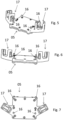
- Figure 5 to Figure 6 show the carrier module 05 in perspective view, in side view and in top view. All functional elements, i.e. the three environment sensors 06 and 07, are dismantled.
- the environment sensor 07 is attached to the top of a base plate 15, which includes the heat sink 26.
- Adjustment bolts 16 are provided on the top of the base plate 15, which ensure exact positioning of the environment sensor 07 on the base plate 15.
- Two fastening receptacles 17 are provided on both sides of the base plate 15, in each of which an environment sensor 06 is pre-mounted in an exact position.
- FIG 8 to Figure 10 show a second embodiment of a carrier module 18, which is also intended for attachment to a roof module.
- the carrier module 18 comprises two fastening receptacles 19, to each of which an environment sensor can be attached in a precise relative position.
- a lens hood 20 is provided between the two fastening receptacles 19.
- an antenna module 22 can be fixed in a mounting recess 21.
- Figure 9 shows the insertion of the antenna module 22 from above into the mounting bracket 21.
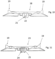
- Figure 10 shows the carrier module 18 with the antenna module 22 attached to it in the mounting holder 21.
- the carrier module 18 is shown in partial section with part of the lens hood 20 omitted.
- FIG 11 shows a further embodiment of a carrier module 23.
- the carrier module 23 largely corresponds to the carrier module 18.
- an antenna module 24 is printed on a receiving surface 25 in the area below the lens hood 20, so that the fastening receptacle 21 is omitted.
Landscapes
- Engineering & Computer Science (AREA)
- Physics & Mathematics (AREA)
- Radar, Positioning & Navigation (AREA)
- Remote Sensing (AREA)
- Computer Networks & Wireless Communication (AREA)
- General Physics & Mathematics (AREA)
- Mechanical Engineering (AREA)
- Electromagnetism (AREA)
- Combustion & Propulsion (AREA)
- Transportation (AREA)
- Chemical & Material Sciences (AREA)
- Fittings On The Vehicle Exterior For Carrying Loads, And Devices For Holding Or Mounting Articles (AREA)
- Support Of Aerials (AREA)
- Body Structure For Vehicles (AREA)
- Optical Radar Systems And Details Thereof (AREA)
Description
- Die Erfindung betrifft ein Dachmodul zur Bildung eines Fahrzeugdachs an einem Kraftfahrzeug nach dem Oberbegriff des Anspruchs 1.
- Gattungsgemäße Dachmodule finden im Fahrzeugbau breite Verwendung, da diese Dachmodule als separate Funktionsmodule vorgefertigt und bei der Montage des Fahrzeuges an das Montageband geliefert werden können. Bei dem Dachmodul kann es sich dabei entweder um ein Teil eins starren Fahrzeugdachs handeln oder um ein Teil einer öffenbaren Dachbaugruppe.
- Im Fahrzeugbau finden autonom bzw. teilautonom fahrende Kraftfahrzeuge immer weitere Verbreitung. Um in der Fahrzeugsteuerung ein autonomes bzw. teilautonomes bzw. fahrerunterstützendes Steuern des Kraftfahrzeuges zu ermöglichen, sind eine Vielzahl von Umfeldsensoren notwendig, die die Umgebung des Kraftfahrzeuges erfassen und daraus die jeweilige Verkehrssituation ermitteln. Die bekannten Umfeldsensoren senden bzw. empfangen dazu entsprechende elektromagnetische Signale, beispielsweise Laserstrahlen oder Radarstrahlen, wobei durch eine entsprechende Signalauswertung ein Datenmodell der Fahrzeugumgebung generiert werden kann.
- Um die Umfeldsensoren vor schädlichen Umwelteinflüssen, beispielsweise Feuchtigkeit und Luftströmungen, zu schützen, sind die bekannten Umfeldsensoren in ein entsprechendes Sensorgehäuse eingebaut. Dieses Sensorgehäuse wird auf der Oberseite des Fahrzeugdachs befestigt, um den Umfeldsensor eine möglichst hochgelegene Beobachtungsposition zu bieten. Nachteilig an der Befestigung des Umfeldsensors zusammen mit einem Sensorgehäuse auf dem Fahrzeugdach ist es, dass dadurch sowohl die aerodynamischen Eigenschaften als auch das Design des Fahrzeuges nachteilig beeinflusst werden. Außerdem erfordert die Befestigung der Sensorgehäuse auf dem Fahrzeugdach eine sehr hohe Präzision, um die Funktionalität der Umfeldsensoren bei der Erfassung der Fahrzeugumgebung zu sichern. Die hochpräzise Fixierung des Sensorgehäuses auf dem Fahrzeugdach ist deshalb zeit- und kostenaufwändig.
- Aus Druckschrift
US 2018/0037267 A1 , die den Oberbegriff des Anspruchs 1 zeigt, ist ein Fahrzeugdach mit einer Blende bekannt, unter der ein Umfeldsensor angeordnet ist, der in einer Wanne liegt. - Druckschrift
EP 3 514 487 A1 offenbart ein Sensorsystem für ein Kraftfahrzeug, umfassend einen Lidar-Sensor. - Druckschrift
DE 10 2017 104 988 A1 zeigt einen Dachsensor eines Fahrzeugs, der ein säulenartiges Gehäuse hat. - Aufgabe der vorliegenden Erfindung ist es deshalb, ein neues Dachmodul vorzuschlagen, das die oben beschriebenen Nachteile des vorbekannten Standes der Technik vermeidet.
- Diese Aufgabe wird durch ein Dachmodul nach der Lehre des Anspruchs 1 gelöst. Vorteilhafte Ausführungsformen der Erfindung sind Gegenstand der Unteransprüche. Bei dem erfindungsgemäßen Dachmodul wird der Umfeldsensor unter der Dachhaut befestigt. Zur Befestigung des Umfeldsensors am Dachmodul unterhalb der Dachhaut dient dabei ein Trägermodul. Durch die Vormontage des Umfeldsensors auf dem Trägermodul wird eine exakte Positionierung des Umfeldsensors problemlos gewährleistet. Außerdem wird der Einbau der Umfeldsensoren in das Dachmodul erheblich vereinfacht, da dazu lediglich das Trägermodul mit dem darauf vormontierten Umfeldsensor im Dachmodul befestigt werden muss. Eine Einzeljustierung des Umfeldsensors im Dachmodul entfällt auf diese Weise. Stattdessen muss lediglich das Trägermodul exakt im Dachmodul ausgerichtet werden. Im Falle einer Funktionsstörung kann das gesamte Trägermodul mit dem darauf befestigten Umfeldsensor in einfacher Weise demontiert und gegebenenfalls ausgetauscht werden.
- Bevorzugt können auf dem Trägermodul mehrere Umfeldsensoren gemeinsam befestigt sein. Durch die gemeinsame Befestigung der Umfeldsensoren auf dem Trägermodul können die Umfeldsensoren in definierter Position auf dem Trägermodul vormontiert werden.
- Um die Positionierung des Trägermoduls relativ zum Dachmodul und damit relativ zur Fahrzeugkarosserie bei der Montage des Trägermoduls zu vereinfachen, ist es besonders vorteilhaft, wenn die Befestigungselemente zur Befestigung des Trägermoduls im Dachmodul mit Justiereinrichtungen ausgestattet sind. Eine solche Justiereinrichtung kann beispielsweise in der Art von Langlöchern im Trägermodul ausgebildet werden. Durch die Justiereinrichtung kann das Trägermodul nach einer Vorfixierung exakt ausgerichtet und anschließend durch Betätigung der Befestigungselemente im Dachmodul fixiert werden. Insbesondere beim Austausch von Trägermodulen ist dies von großem Vorteil.
- Beim Betrieb von bekannten Umfeldsensoren kann es zur Entstehung von Abwärme kommen, durch die die Funktion der Umfeldsensoren beeinträchtigt werden könnte. Gleichzeitig kann die Funktion der Umfeldsensoren auch durch zu tiefe Temperaturen, beispielsweise bei Eis und Schnee, beeinträchtigt werden. Um die Funktion der Umfeldsensoren in allen Temperaturbereichen zu sichern, ist es deshalb besonders vorteilhaft, wenn am Trägermodul zusätzlich zu den Umfeldsensoren auch eine Heiz- und/oder Kühleinrichtung befestigt ist. Mit dieser Heiz- und/oder Kühleinrichtung kann dann ein Thermomanagement realisiert werden, um die Betriebstemperatur der Umfeldsensoren in einem zulässigen Temperaturband zu halten.
- Welche Art von Heizelementen oder Kühlelementen am Dachmodul befestigt werden kann, ist grundsätzlich beliebig. Besonders einfache Bauformen ergeben sich, wenn zur Kühlung der Umfeldsensoren bzw. zur Ableitung der von den Umfeldsensoren abgegebenen Abwärme über das Trägermodul ein Kühllüfter und/oder ein Luftkühlkörper vorgesehen sind.
- Alternativ bzw. additiv dazu kann die Heiz- und/oder Kühleinrichtung auch einen Flüssigkeitskörper oder einen Flüssigkeitskühlkörper umfassen.
- Für den Betrieb von Fahrzeugen, insbesondere von autonom betriebenen Fahrzeugen, ist vielfach eine Funkkommunikation erforderlich, um beispielsweise Informationen mit vorausfahrenden Fahrzeugen oder nachfolgenden Fahrzeugen auszutauschen. Auch ist Funkkommunikation für die Übermittlung von Radio- oder Positionssignalen erforderlich Um solche Art Funkkommunikation durch Senden und Empfangen von Funksignalen realisieren zu können, ist der Einbau von Antennenmodulen in das Fahrzeug erforderlich. Die Antennen müssen dabei so am Fahrzeug positioniert werden, dass durch andere Bestandteile des Fahrzeuges die Funksignale nicht abgeschattet werden. Da die Umfeldsensoren im Dachmodul regelmäßig am höchsten Punkt des Fahrzeuges angeordnet sind, ist dieser Platz besonders geeignet, zusätzlich auch ein Antennenmodul aufzunehmen. Gemäß einer bevorzugten Ausführungsform ist es deshalb vorgesehen, dass an dem Trägermodul neben den Umfeldsensoren auch ein Antennenmodul befestigt ist. Mit diesem Antennenmodul kann dann eine Funkkommunikation mit Sendern bzw. Empfängern außerhalb des Fahrzeuges bzw. mit Sendern und Empfängern innerhalb des Fahrzeuges aufgebaut werden.
- Beim Betrieb von Kraftfahrzeugen in einem autonomen Betriebsmodus, in dem das Fahrzeug nicht von einem Fahrer, sondern von der Fahrzeugsteuerung gesteuert wird, ist es vielfach vorgeschrieben, dass dieser Betriebsmodus durch eine Signalisierungseinrichtung (ADS-Leuchte) signalisiert wird. Zur Einsparung von Kosten ist es dabei besonders vorteilhaft, wenn diese Signalisierungseinrichtung an dem Trägermodul zur Befestigung der Umfeldsensoren befestigt wird. Auf separaten Befestigungsmittel zur Befestigung der Signalisierungseinrichtung am Fahrzeug kann auf diese Weise verzichtet werden.
- In welcher Weise die verschiedenen Bestandteile, insbesondere die Umfeldsensoren, die Heiz- und/oder Kühleinrichtung, das Antennenmodul und/oder die Signalisierungseinrichtung am Trägermodul befestigt werden, ist grundsätzlich beliebig. Um eine exakte Relativpositionierung der unterschiedlichen Bauteile am Trägermodul zu gewährleisten, ist es vorteilhaft, wenn das Trägermodul mehrere Befestigungsaufnahmen umfasst. In den einzelnen Befestigungsaufnahmen kann dann jeweils ein Umfeldsensor, die Heiz- und/oder Kühleinrichtung, ein Antennenmodul und/oder eine Signalisierungseinrichtung in definierter Position relativ zueinander vormontiert werden. Dies bedeutet mit anderen Worten, dass alle am Trägermodul zu befestigenden Funktionselemente in den dafür jeweils vorgesehenen Befestigungsaufnahmen vormontiert werden.
- Für die Befestigung des Trägermoduls am Fahrzeug gibt es verschiedenste Möglichkeiten. Besonders preisgünstig und einfach gelingt dies dadurch, dass das Trägermodul mit den daran vormontierten Umfeldsensoren an einem Rahmenelement oder an einem Rohbauelement oder an einem die Dachhaut des Fahrzeuges bildenden Flächenbauteil befestigt wird. Dadurch wird die notwendige mechanische Stabilität problemlos erreicht. Außerdem kann über diese in der Regel aus Metall gefertigten Bauteile auch Abwärme vom Trägermodul abgeführt werden, um dadurch das Thermomanagement entsprechend zu verbessern.
- Im Hinblick auf einen optimalen Schutz der am Trägermodul befestigten Funktionselemente, insbesondere der Umfeldsensoren, ist es gemäß einer bevorzugten Ausführungsform vorgesehen, dass das Trägermodul in einer vor Feuchtigkeit geschützten Trockenabteilung des Dachmoduls angeordnet ist.
- Soweit das Trägermodul in einer Trockenabteilung angeordnet ist, kann die anfallende Abwärme nicht in einfacher Weise unmittelbar aus der Trockenabteilung abgeleitet werden, da beispielsweise ein Kühllüfter in der Trockenabteilung nicht betrieben werden kann. Zur Lösung dieses Problems kann das Dachmodul zusätzlich ein Wärmeleitelement umfassen. Mit diesem Wärmeleitelement kann dann Wärme vom Trägermodul abgeleitet und in einen Bereich geführt werden, wo die Abwärme problemlos abgeführt werden kann.
- Welche Art von Wärmeleitelement für die Wärmeleitung genutzt wird, ist grundsätzlich beliebig. Besonders einfach und kostengünstig kann dies realisiert werden, wenn das Wärmeleitelement in der Art eines Blechteils ausgebildet ist.
- Insbesondere können Trägerbleche, die beispielsweise zur Befestigung des Dachmoduls an der Fahrzeugkarosserie dienen, zugleich auch als Wärmeleitelement zur Wärmeabfuhr genutzt werden.
- Soweit am Trägermodul zwei Umfeldsensoren mit optischem Funktionsprinzip befestigt sind, muss der Einfall von Streulicht in diese Umfeldsensoren vermieden werden. In einfacher Weise kann dies dadurch realisiert werden, wenn das Trägermodul eine Streulichtblende umfasst, die den Einfall von Streulicht in die Umfeldsensoren verhindert.
- Welche Art von Umfeldsensoren an dem Trägermodul befestigt werden, ist grundsätzlich beliebig. Besonders große Vorteile bietet das Trägermodul bei Umfeldsensoren, die in der Art eines LIDAR-Sensors und/oder in der Art eines Radar-Sensors und/oder in der Art eines Kamera-Sensors und/oder in der Art eines Multi-Kamera-Sensors ausgebildet sind.
- Grundsätzlich kann das Dachmodul nach der Erfindung sowohl bei Personenkraftwagen als auch bei Nutzfahrzeugen, wie Lieferwägen oder Zugmaschinen für LKW, zum Einsatz kommen. Es kann als reines Festdach ausgebildet sein oder auch mit einem Dachöffnungssystem versehen sein und damit eine verschließbare Dachöffnung ausbilden.
- Des Weiteren bildet das Dachmodul nach der Erfindung eine Baueinheit, die in integrierter Weise Einrichtungen zum autonomen Fahren oder zum teilautonomen, durch Fahrzeugassistenzsysteme unterstützten Fahren umfasst und die auf Seiten eines Fahrzeugherstellers auf einen Fahrzeugrohbau aufsetzbar ist.
- Die Erfindung hat auch ein Kraftfahrzeug mit einem Dachmodul der vorstehend beschriebenen Art zum Gegenstand.
- Verschiedene Ausführungsformen der Erfindung sind in den Zeichnungen schematisiert dargestellt und werden nachfolgend beispielhaft erläutert. Es zeigt:
- Figur 1
- ein Dachmodul mit einem Trägermodul zur Befestigung mehrerer Umfeldsensoren im schematisierten Längsschnitt;
- Figur 2
- das Trägermodul des Dachmoduls gemäß
Figur 1 in perspektivischer seitlicher Ansicht; - Figur 3
- das Trägermodul gemäß
Figur 2 in Ansicht von vorne; - Figur 4
- das Trägermodul gemäß
Figur 2 in Ansicht von oben; - Figur 5
- das Trägermodul gemäß
Figur 2 nach der Demontage aller Funktionselemente in perspektivischer seitlicher Ansicht; - Figur 6
- das Trägermodul gemäß
Figur 5 in Ansicht von vorne; - Figur 7
- das Trägermodul gemäß
Figur 5 in Ansicht von oben; - Figur 8
- eine zweite Ausführungsform eines Trägermoduls zur Fixierung mehrerer Funktionselemente in perspektivischer seitlicher Ansicht;
- Figur 9
- das Trägermodul gemäß
Figur 8 in seitlicher Ansicht; - Figur 10
- das Trägermodul gemäß
Figur 8 in Ansicht von vorne; und - Figur 11
- eine dritte Ausführungsform eines Trägermoduls zur Befestigung mehrerer Funktionselemente.
-
Figur 1 zeigt ein Dachmodul 01 zur Befestigung auf dem Fahrzeugdach eines Kraftfahrzeuges, um einen autonomen bzw. teilautonomen Betrieb des Kraftfahrzeuges zu ermöglichen. Das Dachmodul 01 umfasst ein Flächenbauteil 02, dessen Außenseite einen Teil der Dachhaut 03 des Fahrzeuges bildet. Im Inneren des Dachmoduls 01 ist eine Trockenabteilung 04 gebildet, in der ein Trägermodul 05 befestigt ist. Auf dem Trägermodul 05 sind zwei seitliche Umfeldsensoren 06 und ein mittlerer Umfeldsensor 07 vormontiert befestigt. Unter dem mittlerer Umfeldsensor 07 befindet sich ein Kühlkörper 26. Der Kühlkörper 26 umfasst einen Flüssigkeitskühlkörper, der die von den Umfeldsensoren 06 erzeugte Abwärme aufnimmt und ableitet. Im Bereich vor den Umfeldsensoren 06 befindet sich am Dachmodul 01 eine Abdeckung 08, die beispielsweise aus Kunststoff besteht und für die von den Umfeldsensoren 06 abgegebenen elektronmagnetischen Strahlungen, beispielsweise Laserstrahlen oder Radarstrahlen, durchlässig ist. - Das Trägermodul 05 ist mit Befestigungsschrauben 28 auf einem Trägerblech 09 befestigt, das Teil der mechanischen Struktur des Dachmoduls 01 ist. Auf diese Weise dient das Trägerblech 09 zum einen der mechanischen Befestigung des Trägermoduls 05. Zum anderen kann die vom Kühlkörper 26 aufgenommene Abwärme im Trägerblech 09 aus der Trockenabteilung 04 zu einer Kühleinrichtung 27 in einen Feuchtigkeitsbereich 10 abgeleitet werden. Auf diese Weise dient also das Trägerblech 09 auch als Wärmeleitelement. Soweit die Wärmeleitfähigkeit des Trägerblechs 09 nicht ausreicht, kann am Trägerblech 09 zusätzlich eine Heatpipe vorgesehen werden. Im Feuchtigkeitsbereich 10 befindet sich die Kühleinrichtung 27 mit einem Kühllüfter 11, der mit einem Kühlkörper 12 zur Abfuhr der Abwärme zusammenwirkt. Der Kühllüfter 11 kann Frischluft durch Ausnehmungen 13 ansaugen. Die Frischluft wird dann beim Überstreichen des Kühlkörpers 12 erwärmt und wird durch Ausnehmungen 14 wieder ausgeblasen.
-
Figur 2 zeigt das Trägermodul 05 mit den beiden Umfeldsensoren 06 und der dazwischen angeordneten Umfeldsensoren 07 in perspektivischer Ansicht. Durch die Vormontage der Umfeldsensoren 06 und 07 wird eine exakte Positionierung insbesondere der Umfeldsensoren 06 und 07 relativ zueinander realisiert. Außerdem kann bei einer Störung der Umfeldsensoren 06 und 07 das gesamte Trägermodul 05 sehr schnell und einfach ausgetauscht wird. -
Figur 3 und Figur 4 zeigen das Trägermodul 05, die beiden Umfeldsensoren 06 und 07 in Ansicht von vorne bzw. in Ansicht von oben. -
Figur 5 bis Figur 6 zeigen das Trägermodul 05 in perspektivischer Ansicht, in seitlicher Ansicht und in Ansicht von oben. Alle Funktionselemente, das heißt die drei Umfeldsensoren 06 und 07 sind dabei demontiert. der Umfeldsensor 07 wird auf der Oberseite einer Grundplatte 15 befestigt, die den Kühlkörper 26 umfasst. Auf der Oberseite der Grundplatte 15 sind Justierbolzen 16 vorgesehen, die eine exakte Positionierung des Umfeldsensors 07 auf der Grundplatte 15 gewährleisten. An beiden Seiten der Grundplatte 15 sind zwei Befestigungsaufnahmen 17 vorgesehen, in denen jeweils ein Umfeldsensor 06 in exakter Position vormontiert werden. -
Figur 8 bis Figur 10 zeigen eine zweite Ausführungsform eines Trägermoduls 18, das ebenfalls zur Befestigung in einem Dachmodul vorgesehen ist. Das Trägermodul 18 umfasst zwei Befestigungsaufnahmen 19, an denen jeweils ein Umfeldsensor in präziser Relativpositionierung befestigt werden kann. Zwischen den beiden Befestigungsaufnahmen 19 ist eine Streulichtblende 20 vorgesehen. An der Oberseite der Streulichtblende 20 kann in einer Befestigungsaufnahme 21 ein Antennenmodul 22 fixiert werden. -
Figur 9 zeigt das Einstecken des Antennenmoduls 22 von oben in die Befestigungsaufnahme 21. -
Figur 10 zeigt das Trägermodul 18 mit dem daran befestigten Antennenmodul 22 in der Befestigungsaufnahme 21. Das Trägermodul 18 ist dabei im Teilschnitt unter Weglassung eines Teils der Streulichtblende 20 dargestellt. -
Figur 11 zeigt eine weitere Ausführungsform eines Trägermoduls 23. Das Trägermodul 23 stimmt dabei weitgehend mit dem Trägermodul 18 überein. Im Unterscheid zum Trägermodul 18 wird jedoch ein Antennenmodul 24 im Bereich unterhalb der Streulichtblende 20 auf einen Aufnahmefläche 25 aufgedruckt, so dass die Befestigungsaufnahme 21 entfällt. -
- 01
- Dachmodul
- 02
- Flächenbauteil
- 03
- Dachhaut
- 04
- Trockenabteilung
- 05
- Trägermodul
- 06
- Umfeldsensor
- 07
- Umfeldsensor
- 08
- Abdeckung
- 09
- Trägerblech
- 10
- Feuchtigkeitsbereich
- 11
- Kühllüfter
- 12
- Kühlkörper
- 13
- Ausnehmung
- 14
- Ausnehmung
- 15
- Grundplatte
- 16
- Justierbolzen
- 17
- Befestigungsaufnahme
- 18
- Trägermodul
- 19
- Befestigungsaufnahme
- 20
- Streulichtblende
- 21
- Befestigungsaufnahme
- 22
- Antennenmodul
- 23
- Trägermodul
- 24
- Antennenmodul
- 25
- Aufnahmefläche
- 26
- Kühlkörper
- 27
- Kühleinrichtung
- 28
- Befestigungsschraube
Claims (15)
- Dachmodul (01) zur Bildung eines Fahrzeugdachs an einem Kraftfahrzeug, wobei das Dachmodul (01) eine Baueinheit bildet, die in integrierter Weise Einrichtungen zum autonomen Fahren oder teilautonomen Fahren umfasst und auf einen Fahrzeugrohbau aufsetzbar ist, umfassend ein Flächenbauteil (02), dessen Außenoberfläche zumindest bereichsweise die Dachhaut (03) des Fahrzeugdachs bildet, und zumindest zwei Umfeldsensoren (06, 07), die zur Erfassung der Fahrzeugumgebung elektromagnetische Signale senden und/oder empfangen können, und die unter der vom Flächenbauteil (02) gebildeten Dachhaut (03) angeordnet sind, sowie zumindest ein Trägermodul (05, 18, 23), auf dem die zumindest zwei Umfeldsensoren (06, 07) befestigt sind, dadurch gekennzeichnet, dass das Trägermodul (05, 18, 23) an einem Rahmenelement befestigt ist und eine Grundplatte (15) aufweist, an der an beiden Seiten zwei Befestigungsaufnahmen (17) vorgesehen sind, in denen jeweils einer der Umfeldsensoren (06, 07) vormontiert ist.
- Dachmodul nach Anspruch 1, dadurch gekennzeichnet, dass an dem Trägermodul zumindest zwei Umfeldsensoren (06, 07) gemeinsam befestigt sind.
- Dachmodul nach Anspruch 1 oder 2, dadurch gekennzeichnet, dass das Trägermodul (05, 18, 23) zumindest ein Befestigungselement aufweist, mit dem das Trägermodul (05, 18, 23) am Dachmodul (01) befestigbar ist, wobei das Befestigungselement eine Justiereinrichtung aufweist, mit der die Relativposition des Trägermoduls (05, 18, 23) am Dachmodul (01) justierbar ist.
- Dachmodul nach einem der Ansprüche 1 bis 3, dadurch gekennzeichnet, dass an dem Trägermodul (05, 18, 23) zumindest ein Teil einer Heiz- und/oder Kühleinrichtung (27) befestigt ist.
- Dachmodul nach Anspruch 4, dadurch gekennzeichnet, dass die Heiz- und/oder Kühleinrichtung (27) einen Kühllüfter (11) und/oder zumindest einen Kühlkörper (12, 26) umfasst.
- Dachmodul nach Anspruch 4 oder 5, dadurch gekennzeichnet, dass die Heiz- und/oder Kühleinrichtung einen Flüssigkeitsheizkörper oder einen Flüssigkeitskühlkörper umfasst.
- Dachmodul nach einem der Ansprüche 1 bis 6, dadurch gekennzeichnet, dass auf dem Trägermodul (18, 23) zusätzlich ein Antennenmodul (22, 24) befestigt ist.
- Dachmodul nach einem der Ansprüche 1 bis 7, dadurch gekennzeichnet, dass auf dem Trägermodul zusätzlich eine Signalisierungseinrichtung zur Signalisierung eines autonomen Betriebsmodus des Kraftfahrzeugs befestigt ist.
- Dachmodul nach einem der Ansprüche 1 bis 8, dadurch gekennzeichnet, dass das Trägermodul (05, 18, 23) mehrere Befestigungsaufnahmen (17, 19, 21) umfasst, an denen die Umfeldsensoren (06, 07) und/oder die Heiz- und/oder Kühleinrichtung und/oder das Antennenmodul (22) und/oder die Signalisierungseinrichtung in einer definierten Position relativ zueinander vormontierbar sind.
- Dachmodul nach einem der Ansprüche 1 bis 9, dadurch gekennzeichnet, dass das Trägermodul (05, 18, 23) mit den vormontierten Umfeldsensoren an einem Rohbauelement oder an einem die Dachhaut eines Fahrzeugs bildenden Flächenbauteil oder an einem Trägerblech (09) befestigbar ist.
- Dachmodul nach einem der Ansprüche 1 bis 10, dadurch gekennzeichnet, dass das Trägermodul (05, 18, 23) in einer vor Feuchtigkeit geschützten Trockenabteilung (04) des Dachmoduls (01) angeordnet ist.
- Dachmodul nach einem der Ansprüche 1 bis 11, dadurch gekennzeichnet, dass das Dachmodul (05, 18, 23) ein Wärmeleitelement umfasst, wobei mit dem Wärmeleitelement Wärme vom Trägermodul (05, 18, 23) abgeleitet werden kann, wobei das Wärmeleitelement vorzugsweise in der Art eines Blechteils ausgebildet ist, welches insbesondere in der Art eines Trägerblechs (09) ausgebildet ist.
- Dachmodul nach einem der Ansprüche 1 bis 12, dadurch gekennzeichnet, dass das Trägermodul (18, 23) eine Streulichtblende (20) zwischen den beiden Umfeldsensoren umfasst.
- Dachmodul nach einem der Ansprüche 1 bis 13, dadurch gekennzeichnet, dass der Umfeldsensor (06, 07) in der Art eines Lidar-Sensors und/oder in der Art eines Radar-Sensors und/oder in der Art eines Kamera-Sensors und/oder in der Art eines Multikamera-Sensors ausgebildet ist.
- Kraftfahrzeug, umfassend ein Dachmodul nach einem der Ansprüche 1 bis 14.
Applications Claiming Priority (2)
| Application Number | Priority Date | Filing Date | Title |
|---|---|---|---|
| DE102019122197.8A DE102019122197B4 (de) | 2019-08-19 | 2019-08-19 | Dachmodul zur Bildung eines Fahrzeugdachs mit Trägermodul |
| PCT/EP2020/072598 WO2021032559A1 (de) | 2019-08-19 | 2020-08-12 | Dachmodul zur bildung eines fahrzeugdachs mit trägermodul |
Publications (2)
| Publication Number | Publication Date |
|---|---|
| EP4017765A1 EP4017765A1 (de) | 2022-06-29 |
| EP4017765B1 true EP4017765B1 (de) | 2024-07-17 |
Family
ID=72290986
Family Applications (1)
| Application Number | Title | Priority Date | Filing Date |
|---|---|---|---|
| EP20764304.0A Active EP4017765B1 (de) | 2019-08-19 | 2020-08-12 | Dachmodul zur bildung eines fahrzeugdachs mit trägermodul |
Country Status (6)
| Country | Link |
|---|---|
| US (1) | US11813992B2 (de) |
| EP (1) | EP4017765B1 (de) |
| KR (1) | KR20220038155A (de) |
| CN (1) | CN114286765B (de) |
| DE (1) | DE102019122197B4 (de) |
| WO (1) | WO2021032559A1 (de) |
Families Citing this family (13)
| Publication number | Priority date | Publication date | Assignee | Title |
|---|---|---|---|---|
| US12032056B2 (en) * | 2020-09-08 | 2024-07-09 | Lyft, Inc. | Universal sensor assembly for vehicles |
| JP7355003B2 (ja) * | 2020-12-25 | 2023-10-03 | トヨタ自動車株式会社 | 車両用センサ取り付け構造 |
| DE102021118434B4 (de) | 2021-07-16 | 2023-06-07 | Webasto SE | Dachanordnung, Dachmodul und Kraftfahrzeug mit einer Kühleinrichtung |
| DE102022103422A1 (de) * | 2022-02-14 | 2023-08-17 | Webasto SE | Fahrzeugdach mit an Trägereinrichtung befestigter Halteeinrichtung für mindestens zwei Umfeldsensoren |
| DE102022103830A1 (de) * | 2022-02-17 | 2023-08-17 | Webasto SE | Dachmodul mit einer Sende- und/oder Empfangseinrichtung |
| DE102022113740B4 (de) * | 2022-05-31 | 2026-02-05 | Webasto SE | Dachanordnung mit einem Dachöffnungssystem und einer Klimaeinrichtung |
| DE102022114950B3 (de) * | 2022-06-14 | 2023-12-07 | Webasto SE | Kraftfahrzeug mit einem Dachmodul und mindestens zwei Umfeldsensoren |
| US12409791B2 (en) | 2022-08-09 | 2025-09-09 | Ford Global Technologies, Llc | Vehicle sensor assembly |
| US12391188B2 (en) | 2022-10-27 | 2025-08-19 | Honda Motor Co., Ltd. | Eye plate lifting feature with roof side applique |
| US12208745B2 (en) | 2022-10-27 | 2025-01-28 | Honda Motor Co., Ltd. | Water intrusion prevention system for roof top module |
| US12054101B2 (en) | 2022-10-27 | 2024-08-06 | Honda Motor Co., Ltd. | Roof top sensor module with internal bracket |
| DE102023109823A1 (de) * | 2023-04-19 | 2024-10-24 | Webasto SE | Dachmodul und Kraftfahrzeug mit einer Kühleinrichtung |
| DE102023131945A1 (de) * | 2023-11-16 | 2025-05-22 | Man Truck & Bus Se | Fahrerhaus für ein teilautonom oder autonom betreibbares Nutzfahrzeug und Nutzfahrzeug mit dem Fahrerhaus |
Family Cites Families (11)
| Publication number | Priority date | Publication date | Assignee | Title |
|---|---|---|---|---|
| EP1501703B1 (de) * | 2002-04-29 | 2016-05-11 | Magna Mirrors Holding GmbH | Abdeckmodul |
| JP2012232679A (ja) | 2011-05-02 | 2012-11-29 | Kojima Press Industry Co Ltd | 車載用アンテナ装置 |
| FR3023530A1 (fr) * | 2014-07-09 | 2016-01-15 | Valeo Vision | Module formant un element de carrosserie pour vehicule automobile participant a l'esthetique exterieure du vehicule |
| US10046713B2 (en) | 2016-01-04 | 2018-08-14 | Ford Global Technologies, Llc | Sensor apparatus |
| US9885526B2 (en) | 2016-03-11 | 2018-02-06 | Ford Global Technologies, Llc | Cooling system for vehicle sensor modules |
| US10071773B2 (en) * | 2016-08-04 | 2018-09-11 | Toyota Motor Engineering & Manufacturing North America, Inc. | Vehicle roof structures for concealing one or more sensors |
| CN109690244B (zh) * | 2016-09-15 | 2021-09-17 | 株式会社小糸制作所 | 传感器系统、传感器模块及灯装置 |
| US10514303B2 (en) * | 2017-06-29 | 2019-12-24 | Ford Global Technologies, Llc | Sensor pod with breathable cabin interface |
| FR3074120B1 (fr) * | 2017-11-24 | 2019-11-08 | Compagnie Plastic Omnium | Systeme de fixation d'un capteur de detection d'obstacles pour vehicule automobile |
| US10569721B2 (en) * | 2018-01-04 | 2020-02-25 | Toyota Motor Engineering & Manufacturing North America, Inc. | Autonomous radar roof module |
| US10668793B2 (en) * | 2018-01-05 | 2020-06-02 | Toyota Motor Engineering & Manufacturing North America, Inc. | Retractable autonomous roof panel |
-
2019
- 2019-08-19 DE DE102019122197.8A patent/DE102019122197B4/de active Active
-
2020
- 2020-08-12 CN CN202080058722.6A patent/CN114286765B/zh active Active
- 2020-08-12 EP EP20764304.0A patent/EP4017765B1/de active Active
- 2020-08-12 WO PCT/EP2020/072598 patent/WO2021032559A1/de not_active Ceased
- 2020-08-12 US US17/633,054 patent/US11813992B2/en active Active
- 2020-08-12 KR KR1020227006406A patent/KR20220038155A/ko not_active Ceased
Also Published As
| Publication number | Publication date |
|---|---|
| KR20220038155A (ko) | 2022-03-25 |
| DE102019122197B4 (de) | 2021-03-11 |
| US20220266763A1 (en) | 2022-08-25 |
| US11813992B2 (en) | 2023-11-14 |
| WO2021032559A1 (de) | 2021-02-25 |
| CN114286765A (zh) | 2022-04-05 |
| DE102019122197A1 (de) | 2021-02-25 |
| CN114286765B (zh) | 2024-04-30 |
| EP4017765A1 (de) | 2022-06-29 |
Similar Documents
| Publication | Publication Date | Title |
|---|---|---|
| DE102019122197B4 (de) | Dachmodul zur Bildung eines Fahrzeugdachs mit Trägermodul | |
| DE102019122190B4 (de) | Dachmodul zur Bildung eines Fahrzeugdachs mit Kühleinrichtung | |
| EP3145755B1 (de) | Assistenzsystem eines kraftfahrzeugs | |
| DE102016010230B4 (de) | Kühlanordnung für ein Fahrerassistenzsystem | |
| DE112004001717B4 (de) | Befestigungsanordnung zur Anordnung einer fahrzeugseitigen Schaltkreiseinheit an einer Fahrzeugkarosserie | |
| EP1986887B1 (de) | Bilderfassungseinrichtung für ein fahrerassistenzsystem | |
| DE102021118434B4 (de) | Dachanordnung, Dachmodul und Kraftfahrzeug mit einer Kühleinrichtung | |
| DE102009060392B4 (de) | Sensoreinrichtung für ein Kraftfahrzeug | |
| DE102021122866A1 (de) | Dachmodul mit einer Kühleinrichtung | |
| EP1972483B1 (de) | Fahrzeug mit einem Head-Up-Display | |
| DE102008031256A1 (de) | Beleuchtungseinheit für Fahrzeugscheinwerfer und Fahrzeugscheinwerfer | |
| DE102019122184B3 (de) | Dachmodul zur Bildung eines Fahrzeugdachs mit Antennenmodul | |
| DE102012013193A1 (de) | Elektronisches Modul | |
| DE102017123973A1 (de) | Kamera für ein Kraftfahrzeug mit spezifischer Anordnung eines Schaltungsträgers an einem Gehäusevorderteil, Verfahren zur Montage einer Kamera, sowie Kraftfahrzeug | |
| DE102022105578B4 (de) | Strömungsleiteinrichtung für ein Kraftfahrzeug | |
| DE102014220714B4 (de) | Vorrichtung zur Befestigung einer Kamera an der Innenseite einer Fahrzeugscheibe | |
| DE102023108471A1 (de) | Sensormodul zur Anordnung an einem Kraftfahrzeug | |
| DE102012017942A1 (de) | Halteeinrichtung zum Halten einer Sensorvorrichtung an einer Scheibe eines Kraftfahrzeugs | |
| DE102021212415A1 (de) | Modul zur Aufnahme einer Hauptbeleuchtungseinrichtung und mindestens einer Funktionseinheit | |
| DE102019201417A1 (de) | Kühlvorrichtung für einen Sensor eines Fortbewegungsmittels und Sensorbaugruppe umfassend die Kühlvorrichtung | |
| DE102016100977A1 (de) | Antennenmodul für ein Kraftfahrzeug, Fahrerassistenzsystem sowie Kraftfahrzeug | |
| DE102022200782A1 (de) | Außenrückblickanordnung für Straßenfahrzeuge und Verfahren zur Herstellung einer Außenrückblickanordnung für Straßenfahrzeuge | |
| DE19820703C1 (de) | Elektrische Einrichtung, insbesondere eine Abstandsregeleinrichtung für ein Kraftfahrzeug | |
| DE19839927A1 (de) | Elektrische Einrichtung, insbesondere eine Abstandsregeleinrichtung eines Kraftfahrzeuges | |
| EP3109078A1 (de) | Haube einer aufdachklimaanlage für ein strassenfahrzeug |
Legal Events
| Date | Code | Title | Description |
|---|---|---|---|
| STAA | Information on the status of an ep patent application or granted ep patent |
Free format text: STATUS: UNKNOWN |
|
| STAA | Information on the status of an ep patent application or granted ep patent |
Free format text: STATUS: THE INTERNATIONAL PUBLICATION HAS BEEN MADE |
|
| PUAI | Public reference made under article 153(3) epc to a published international application that has entered the european phase |
Free format text: ORIGINAL CODE: 0009012 |
|
| STAA | Information on the status of an ep patent application or granted ep patent |
Free format text: STATUS: REQUEST FOR EXAMINATION WAS MADE |
|
| 17P | Request for examination filed |
Effective date: 20220310 |
|
| AK | Designated contracting states |
Kind code of ref document: A1 Designated state(s): AL AT BE BG CH CY CZ DE DK EE ES FI FR GB GR HR HU IE IS IT LI LT LU LV MC MK MT NL NO PL PT RO RS SE SI SK SM TR |
|
| DAV | Request for validation of the european patent (deleted) | ||
| DAX | Request for extension of the european patent (deleted) | ||
| GRAP | Despatch of communication of intention to grant a patent |
Free format text: ORIGINAL CODE: EPIDOSNIGR1 |
|
| STAA | Information on the status of an ep patent application or granted ep patent |
Free format text: STATUS: GRANT OF PATENT IS INTENDED |
|
| INTG | Intention to grant announced |
Effective date: 20240219 |
|
| RBV | Designated contracting states (corrected) |
Designated state(s): AL AT BE BG CH CY CZ DK EE ES FI FR GB GR HR HU IE IS IT LI LT LU LV MC MK MT NL NO PL PT RO RS SE SI SK SM TR |
|
| REG | Reference to a national code |
Ref country code: DE Ref legal event code: R108 |
|
| GRAS | Grant fee paid |
Free format text: ORIGINAL CODE: EPIDOSNIGR3 |
|
| GRAA | (expected) grant |
Free format text: ORIGINAL CODE: 0009210 |
|
| STAA | Information on the status of an ep patent application or granted ep patent |
Free format text: STATUS: THE PATENT HAS BEEN GRANTED |
|
| AK | Designated contracting states |
Kind code of ref document: B1 Designated state(s): AL AT BE BG CH CY CZ DK EE ES FI FR GB GR HR HU IE IS IT LI LT LU LV MC MK MT NL NO PL PT RO RS SE SI SK SM TR |
|
| REG | Reference to a national code |
Ref country code: CH Ref legal event code: EP |
|
| REG | Reference to a national code |
Ref country code: IE Ref legal event code: FG4D Free format text: LANGUAGE OF EP DOCUMENT: GERMAN |
|
| REG | Reference to a national code |
Ref country code: LT Ref legal event code: MG9D |
|
| REG | Reference to a national code |
Ref country code: NL Ref legal event code: MP Effective date: 20240717 |
|
| PG25 | Lapsed in a contracting state [announced via postgrant information from national office to epo] |
Ref country code: PT Free format text: LAPSE BECAUSE OF FAILURE TO SUBMIT A TRANSLATION OF THE DESCRIPTION OR TO PAY THE FEE WITHIN THE PRESCRIBED TIME-LIMIT Effective date: 20241118 |
|
| PG25 | Lapsed in a contracting state [announced via postgrant information from national office to epo] |
Ref country code: NL Free format text: LAPSE BECAUSE OF FAILURE TO SUBMIT A TRANSLATION OF THE DESCRIPTION OR TO PAY THE FEE WITHIN THE PRESCRIBED TIME-LIMIT Effective date: 20240717 |
|
| PG25 | Lapsed in a contracting state [announced via postgrant information from national office to epo] |
Ref country code: PT Free format text: LAPSE BECAUSE OF FAILURE TO SUBMIT A TRANSLATION OF THE DESCRIPTION OR TO PAY THE FEE WITHIN THE PRESCRIBED TIME-LIMIT Effective date: 20241118 Ref country code: NL Free format text: LAPSE BECAUSE OF FAILURE TO SUBMIT A TRANSLATION OF THE DESCRIPTION OR TO PAY THE FEE WITHIN THE PRESCRIBED TIME-LIMIT Effective date: 20240717 |
|
| PG25 | Lapsed in a contracting state [announced via postgrant information from national office to epo] |
Ref country code: NO Free format text: LAPSE BECAUSE OF FAILURE TO SUBMIT A TRANSLATION OF THE DESCRIPTION OR TO PAY THE FEE WITHIN THE PRESCRIBED TIME-LIMIT Effective date: 20241017 |
|
| PG25 | Lapsed in a contracting state [announced via postgrant information from national office to epo] |
Ref country code: PL Free format text: LAPSE BECAUSE OF FAILURE TO SUBMIT A TRANSLATION OF THE DESCRIPTION OR TO PAY THE FEE WITHIN THE PRESCRIBED TIME-LIMIT Effective date: 20240717 Ref country code: GR Free format text: LAPSE BECAUSE OF FAILURE TO SUBMIT A TRANSLATION OF THE DESCRIPTION OR TO PAY THE FEE WITHIN THE PRESCRIBED TIME-LIMIT Effective date: 20241018 Ref country code: FI Free format text: LAPSE BECAUSE OF FAILURE TO SUBMIT A TRANSLATION OF THE DESCRIPTION OR TO PAY THE FEE WITHIN THE PRESCRIBED TIME-LIMIT Effective date: 20240717 |
|
| PG25 | Lapsed in a contracting state [announced via postgrant information from national office to epo] |
Ref country code: BG Free format text: LAPSE BECAUSE OF FAILURE TO SUBMIT A TRANSLATION OF THE DESCRIPTION OR TO PAY THE FEE WITHIN THE PRESCRIBED TIME-LIMIT Effective date: 20240717 |
|
| PG25 | Lapsed in a contracting state [announced via postgrant information from national office to epo] |
Ref country code: LV Free format text: LAPSE BECAUSE OF FAILURE TO SUBMIT A TRANSLATION OF THE DESCRIPTION OR TO PAY THE FEE WITHIN THE PRESCRIBED TIME-LIMIT Effective date: 20240717 |
|
| PG25 | Lapsed in a contracting state [announced via postgrant information from national office to epo] |
Ref country code: IS Free format text: LAPSE BECAUSE OF FAILURE TO SUBMIT A TRANSLATION OF THE DESCRIPTION OR TO PAY THE FEE WITHIN THE PRESCRIBED TIME-LIMIT Effective date: 20241117 |
|
| PG25 | Lapsed in a contracting state [announced via postgrant information from national office to epo] |
Ref country code: HR Free format text: LAPSE BECAUSE OF FAILURE TO SUBMIT A TRANSLATION OF THE DESCRIPTION OR TO PAY THE FEE WITHIN THE PRESCRIBED TIME-LIMIT Effective date: 20240717 |
|
| PG25 | Lapsed in a contracting state [announced via postgrant information from national office to epo] |
Ref country code: ES Free format text: LAPSE BECAUSE OF FAILURE TO SUBMIT A TRANSLATION OF THE DESCRIPTION OR TO PAY THE FEE WITHIN THE PRESCRIBED TIME-LIMIT Effective date: 20240717 Ref country code: RS Free format text: LAPSE BECAUSE OF FAILURE TO SUBMIT A TRANSLATION OF THE DESCRIPTION OR TO PAY THE FEE WITHIN THE PRESCRIBED TIME-LIMIT Effective date: 20241017 |
|
| PG25 | Lapsed in a contracting state [announced via postgrant information from national office to epo] |
Ref country code: RS Free format text: LAPSE BECAUSE OF FAILURE TO SUBMIT A TRANSLATION OF THE DESCRIPTION OR TO PAY THE FEE WITHIN THE PRESCRIBED TIME-LIMIT Effective date: 20241017 Ref country code: PL Free format text: LAPSE BECAUSE OF FAILURE TO SUBMIT A TRANSLATION OF THE DESCRIPTION OR TO PAY THE FEE WITHIN THE PRESCRIBED TIME-LIMIT Effective date: 20240717 Ref country code: NO Free format text: LAPSE BECAUSE OF FAILURE TO SUBMIT A TRANSLATION OF THE DESCRIPTION OR TO PAY THE FEE WITHIN THE PRESCRIBED TIME-LIMIT Effective date: 20241017 Ref country code: LV Free format text: LAPSE BECAUSE OF FAILURE TO SUBMIT A TRANSLATION OF THE DESCRIPTION OR TO PAY THE FEE WITHIN THE PRESCRIBED TIME-LIMIT Effective date: 20240717 Ref country code: IS Free format text: LAPSE BECAUSE OF FAILURE TO SUBMIT A TRANSLATION OF THE DESCRIPTION OR TO PAY THE FEE WITHIN THE PRESCRIBED TIME-LIMIT Effective date: 20241117 Ref country code: HR Free format text: LAPSE BECAUSE OF FAILURE TO SUBMIT A TRANSLATION OF THE DESCRIPTION OR TO PAY THE FEE WITHIN THE PRESCRIBED TIME-LIMIT Effective date: 20240717 Ref country code: GR Free format text: LAPSE BECAUSE OF FAILURE TO SUBMIT A TRANSLATION OF THE DESCRIPTION OR TO PAY THE FEE WITHIN THE PRESCRIBED TIME-LIMIT Effective date: 20241018 Ref country code: FI Free format text: LAPSE BECAUSE OF FAILURE TO SUBMIT A TRANSLATION OF THE DESCRIPTION OR TO PAY THE FEE WITHIN THE PRESCRIBED TIME-LIMIT Effective date: 20240717 Ref country code: ES Free format text: LAPSE BECAUSE OF FAILURE TO SUBMIT A TRANSLATION OF THE DESCRIPTION OR TO PAY THE FEE WITHIN THE PRESCRIBED TIME-LIMIT Effective date: 20240717 Ref country code: BG Free format text: LAPSE BECAUSE OF FAILURE TO SUBMIT A TRANSLATION OF THE DESCRIPTION OR TO PAY THE FEE WITHIN THE PRESCRIBED TIME-LIMIT Effective date: 20240717 |
|
| REG | Reference to a national code |
Ref country code: CH Ref legal event code: PL |
|
| PG25 | Lapsed in a contracting state [announced via postgrant information from national office to epo] |
Ref country code: RO Free format text: LAPSE BECAUSE OF FAILURE TO SUBMIT A TRANSLATION OF THE DESCRIPTION OR TO PAY THE FEE WITHIN THE PRESCRIBED TIME-LIMIT Effective date: 20240717 Ref country code: SM Free format text: LAPSE BECAUSE OF FAILURE TO SUBMIT A TRANSLATION OF THE DESCRIPTION OR TO PAY THE FEE WITHIN THE PRESCRIBED TIME-LIMIT Effective date: 20240717 Ref country code: DK Free format text: LAPSE BECAUSE OF FAILURE TO SUBMIT A TRANSLATION OF THE DESCRIPTION OR TO PAY THE FEE WITHIN THE PRESCRIBED TIME-LIMIT Effective date: 20240717 |
|
| PG25 | Lapsed in a contracting state [announced via postgrant information from national office to epo] |
Ref country code: LU Free format text: LAPSE BECAUSE OF NON-PAYMENT OF DUE FEES Effective date: 20240812 |
|
| PG25 | Lapsed in a contracting state [announced via postgrant information from national office to epo] |
Ref country code: MC Free format text: LAPSE BECAUSE OF FAILURE TO SUBMIT A TRANSLATION OF THE DESCRIPTION OR TO PAY THE FEE WITHIN THE PRESCRIBED TIME-LIMIT Effective date: 20240717 Ref country code: CH Free format text: LAPSE BECAUSE OF NON-PAYMENT OF DUE FEES Effective date: 20240831 Ref country code: EE Free format text: LAPSE BECAUSE OF FAILURE TO SUBMIT A TRANSLATION OF THE DESCRIPTION OR TO PAY THE FEE WITHIN THE PRESCRIBED TIME-LIMIT Effective date: 20240717 |
|
| PG25 | Lapsed in a contracting state [announced via postgrant information from national office to epo] |
Ref country code: CZ Free format text: LAPSE BECAUSE OF FAILURE TO SUBMIT A TRANSLATION OF THE DESCRIPTION OR TO PAY THE FEE WITHIN THE PRESCRIBED TIME-LIMIT Effective date: 20240717 |
|
| PG25 | Lapsed in a contracting state [announced via postgrant information from national office to epo] |
Ref country code: SK Free format text: LAPSE BECAUSE OF FAILURE TO SUBMIT A TRANSLATION OF THE DESCRIPTION OR TO PAY THE FEE WITHIN THE PRESCRIBED TIME-LIMIT Effective date: 20240717 |
|
| PLBE | No opposition filed within time limit |
Free format text: ORIGINAL CODE: 0009261 |
|
| STAA | Information on the status of an ep patent application or granted ep patent |
Free format text: STATUS: NO OPPOSITION FILED WITHIN TIME LIMIT |
|
| 26N | No opposition filed |
Effective date: 20250422 |
|
| REG | Reference to a national code |
Ref country code: BE Ref legal event code: MM Effective date: 20240831 |
|
| PG25 | Lapsed in a contracting state [announced via postgrant information from national office to epo] |
Ref country code: BE Free format text: LAPSE BECAUSE OF NON-PAYMENT OF DUE FEES Effective date: 20240831 |
|
| PG25 | Lapsed in a contracting state [announced via postgrant information from national office to epo] |
Ref country code: IE Free format text: LAPSE BECAUSE OF NON-PAYMENT OF DUE FEES Effective date: 20240812 |
|
| PG25 | Lapsed in a contracting state [announced via postgrant information from national office to epo] |
Ref country code: SE Free format text: LAPSE BECAUSE OF FAILURE TO SUBMIT A TRANSLATION OF THE DESCRIPTION OR TO PAY THE FEE WITHIN THE PRESCRIBED TIME-LIMIT Effective date: 20240717 |
|
| PGFP | Annual fee paid to national office [announced via postgrant information from national office to epo] |
Ref country code: GB Payment date: 20250822 Year of fee payment: 6 |
|
| PGFP | Annual fee paid to national office [announced via postgrant information from national office to epo] |
Ref country code: FR Payment date: 20250821 Year of fee payment: 6 Ref country code: AT Payment date: 20251020 Year of fee payment: 5 |
|
| PG25 | Lapsed in a contracting state [announced via postgrant information from national office to epo] |
Ref country code: CY Free format text: LAPSE BECAUSE OF FAILURE TO SUBMIT A TRANSLATION OF THE DESCRIPTION OR TO PAY THE FEE WITHIN THE PRESCRIBED TIME-LIMIT; INVALID AB INITIO Effective date: 20200812 Ref country code: IT Free format text: LAPSE BECAUSE OF FAILURE TO SUBMIT A TRANSLATION OF THE DESCRIPTION OR TO PAY THE FEE WITHIN THE PRESCRIBED TIME-LIMIT Effective date: 20240717 |
|
| PG25 | Lapsed in a contracting state [announced via postgrant information from national office to epo] |
Ref country code: HU Free format text: LAPSE BECAUSE OF FAILURE TO SUBMIT A TRANSLATION OF THE DESCRIPTION OR TO PAY THE FEE WITHIN THE PRESCRIBED TIME-LIMIT; INVALID AB INITIO Effective date: 20200812 |