EP4017569B1 - Katheterverwaltungsvorrichtung - Google Patents
Katheterverwaltungsvorrichtung Download PDFInfo
- Publication number
- EP4017569B1 EP4017569B1 EP20855500.3A EP20855500A EP4017569B1 EP 4017569 B1 EP4017569 B1 EP 4017569B1 EP 20855500 A EP20855500 A EP 20855500A EP 4017569 B1 EP4017569 B1 EP 4017569B1
- Authority
- EP
- European Patent Office
- Prior art keywords
- plate
- guidewire
- lower plate
- grooves
- catheter shaft
- Prior art date
- Legal status (The legal status is an assumption and is not a legal conclusion. Google has not performed a legal analysis and makes no representation as to the accuracy of the status listed.)
- Active
Links
Images


Classifications
-
- A—HUMAN NECESSITIES
- A61—MEDICAL OR VETERINARY SCIENCE; HYGIENE
- A61M—DEVICES FOR INTRODUCING MEDIA INTO, OR ONTO, THE BODY; DEVICES FOR TRANSDUCING BODY MEDIA OR FOR TAKING MEDIA FROM THE BODY; DEVICES FOR PRODUCING OR ENDING SLEEP OR STUPOR
- A61M25/00—Catheters; Hollow probes
- A61M25/01—Introducing, guiding, advancing, emplacing or holding catheters
- A61M25/02—Holding devices, e.g. on the body
-
- A—HUMAN NECESSITIES
- A61—MEDICAL OR VETERINARY SCIENCE; HYGIENE
- A61M—DEVICES FOR INTRODUCING MEDIA INTO, OR ONTO, THE BODY; DEVICES FOR TRANSDUCING BODY MEDIA OR FOR TAKING MEDIA FROM THE BODY; DEVICES FOR PRODUCING OR ENDING SLEEP OR STUPOR
- A61M25/00—Catheters; Hollow probes
- A61M2025/0008—Catheters; Hollow probes having visible markings on its surface, i.e. visible to the naked eye, for any purpose, e.g. insertion depth markers, rotational markers or identification of type
-
- A—HUMAN NECESSITIES
- A61—MEDICAL OR VETERINARY SCIENCE; HYGIENE
- A61M—DEVICES FOR INTRODUCING MEDIA INTO, OR ONTO, THE BODY; DEVICES FOR TRANSDUCING BODY MEDIA OR FOR TAKING MEDIA FROM THE BODY; DEVICES FOR PRODUCING OR ENDING SLEEP OR STUPOR
- A61M25/00—Catheters; Hollow probes
- A61M25/01—Introducing, guiding, advancing, emplacing or holding catheters
- A61M2025/0177—Introducing, guiding, advancing, emplacing or holding catheters having external means for receiving guide wires, wires or stiffening members, e.g. loops, clamps or lateral tubes
-
- A—HUMAN NECESSITIES
- A61—MEDICAL OR VETERINARY SCIENCE; HYGIENE
- A61M—DEVICES FOR INTRODUCING MEDIA INTO, OR ONTO, THE BODY; DEVICES FOR TRANSDUCING BODY MEDIA OR FOR TAKING MEDIA FROM THE BODY; DEVICES FOR PRODUCING OR ENDING SLEEP OR STUPOR
- A61M25/00—Catheters; Hollow probes
- A61M25/01—Introducing, guiding, advancing, emplacing or holding catheters
- A61M25/02—Holding devices, e.g. on the body
- A61M2025/024—Holding devices, e.g. on the body having a clip or clamp system
-
- A—HUMAN NECESSITIES
- A61—MEDICAL OR VETERINARY SCIENCE; HYGIENE
- A61M—DEVICES FOR INTRODUCING MEDIA INTO, OR ONTO, THE BODY; DEVICES FOR TRANSDUCING BODY MEDIA OR FOR TAKING MEDIA FROM THE BODY; DEVICES FOR PRODUCING OR ENDING SLEEP OR STUPOR
- A61M25/00—Catheters; Hollow probes
- A61M25/01—Introducing, guiding, advancing, emplacing or holding catheters
- A61M25/02—Holding devices, e.g. on the body
- A61M2025/028—Holding devices, e.g. on the body having a mainly rigid support structure
Definitions
- catheters and/or guidewires are used to access target areas of the body using minimally invasive techniques. For example, blockages in the heart are treated using angioplasty catheters or stent delivery catheters thereby avoiding open heart surgery.
- Guidewires are often used to facilitate advancement of the diagnostic or therapeutic catheter to the target area, and often multiple catheters or multiple guidewires may be used during the procedure.
- US 5389082 describes an intravenous line separator system comprising a cover plate having an upper surface, a lower surface, a first end, and a second end, a plurality of U-shaped grooves formed within the cover plate, a hinge pin positioned within the first end of the cover plate, a C-shaped locking element integral with the second end of the cover plate; and a base plate having an upper surface, a lower surface, a first end, and a second end, a plurality of U-shaped grooves, the U-shaped grooves of the base plate corresponding in number and position to the U-shaped grooves of the cover plate, a hinge pin receiving means positioned at the first end of the base plate, the hinge pin of the cover plate adapted to be received within the hinge pin receiving means, the hinge pin and the hinge pin receiving means together serving to pivotally interconnect the base plate and the cover plate, a tongue locking element integral with the second end of the base plate, the C-shaped locking element adapted to receive the tongue locking element and secure the cover plate to the base plate.
- US 7457506 describes a line organizer, comprising an elongate lower portion, wherein the lower portion includes at least two lower aperture portions formed in the lower portion; a base member associated with the lower portion; an elongate upper portion, wherein the upper portion includes at least two upper aperture portions formed in the upper portion, wherein each upper aperture portion corresponds to a lower aperture portion, and wherein the upper portion is coupled to the lower portion via a hinge means, such that the upper portion and the lower portion are pivotable relative to one another and are pivotable between a closed position and an open position; and a locking means associated with the upper portion and the lower portion, wherein the locking means is capable of maintaining the upper and lower portions in the closed position.
- US 2013/079722 describes a fixture for fixing a tubular catheter to a skin of a patient.
- the catheter fixture is provided with a plate shaped fixture main body, a fixing member that is configured separately from the fixture main body, and a pivot connecting shaft.
- the plate shaped fixture main body includes a retention part where a catheter retaining groove is formed, and a pair of winged pieces.
- the pivot connecting shaft both connects the fixture main body and the fixing member and acts as the pivot axis of the fixing member.
- the fixing member has a pivoting action along a horizontal plane direction of the fixture main body centrally around the pivot connecting shaft. When doing so, the catheter retaining groove is covered by the fixing member thereby fixing the catheter.
- US 2007/276336 describes an anchoring system for an elongated medical article comprises an anchor pad and a retainer mounted upon the anchor pad.
- the retainer includes a base, a cover, and a compressible member including a receptacle into which the medical article to be retained is placed. When the cover is closed, the medical article is secured within the receptacle by the pressure of the compressible member and the cover upon the medical article.
- One or more biasing members act upon the compressible member to increase the frictional forces acting on the retained section of the medical article.
- the receptacle may form a channel that follows a curved path through the retainer.
- the retainer may also include guide extensions to support the medical article along a transverse bend toward the skin of the patient.
- EP 0567029 describes a medical device for securing tubing such as intravenous catheter tubing to a patient.
- the device is made up of two lobes , each being made up of a channel and a tab .
- the device is hinged so that the tabs can be brought together.
- the tubing is gripped between the gripping channels (28,30).
- the gripping channels have specially adapted surfaces to facilitate the gripping of the tubing .
- the gripping channels may also be lined with a tacky material or contoured liners.
- KR 2011/0070462 describes a fixing clip for a catheter to rigidly fix various catheters for a long time without giving a stimulus to the skin of a patient.
- the fixing clip comprises: a floor fixed to a fixing pad; first and second sidewalls formed in both sides of the floor; front and rear opening parts which open the front and rear; a receiving unit which is projected from the top in the front of the floor and consists of a compartment post dividing the front opening part; first and second doors which open the upper part of the receiving unit, are connected to the upper end of the first and second sidewalls by a hinge unit, and are coupled with each other by a connecting unit. Further devices are disclosed in
- Figs. 1-3 illustrate one example of a catheter management device.
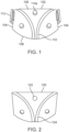
- Fig. 1 illustrates an example of a bottom plate 102 that may be used in a catheter or guidewire management device.
- the bottom plate may be a flat planar plate of any shape.
- the plate has two linear lateral sides 104 and an arcuate distal edge 108 and a linear proximal edge 106.
- the linear proximal edge 106 may be facing the operator and the arcuate distal edge 108 may be facing the patient, or the opposite orientation may be used where the linear proximal edge faces toward the patient and the arcuate edge faces toward the operator.
- Any number of grooves 110 may be disposed in the upper surface of the bottom plate.
- An arcuate groove 110 may provide a smooth curve that a catheter shaft or guidewire may navigate as it is being slidably advanced through the groove.
- One or more pins 110a here three, extend up from the top surface of the bottom plate and serve as alignment pins when the bottom plate is aligned with holes in a top plate as will be discussed below. Although this is not intended to be limiting, and the pins may be disposed on the top plate and the holes on the bottom plate, or a combination of pins and holes maybe on both plates.
- a wall 112 extends vertically away from the top surface of the plate. The walls serve as alignment elements to help align a top plate with the bottom plate 102 when the two plates are coupled together.
- Fig. 2 illustrates an example of a top plate 120 which may be used with the bottom plate 102 in Fig. 1 to form a catheter or guidewire management device.
- the top plate 120 is also a flat planar plate and has a shape that matches the bottom plate 102 shape such that when the two plates are stacked on top of one another, they form a uniform profile.
- this is not intended to be limiting, and any shape may be used.
- the shape may be compact enough to easily fit in an operator's hand for easy carrying and manipulation, or the device may rest on a surface.
- the top plate 120 includes alignment holes 122 which extend through the top plate and they are positioned to align with and cooperate with the alignment pins 110a in the bottom plate 102.
- each groove may be roughly half the diameter of a catheter shaft or a guidewire, although this is not intended to be limiting. In some examples the grooves may be less than half the diameter of the catheter shaft or guidewire and therefore when the two plates are coupled together they will capture the guidewire or catheter shaft in the resulting channel and due to the tight fit, this prevents axial movement of the catheter shaft or guidewire along the shaft. In other examples the groove may be larger than half the diameter of the guidewire or catheter shaft to allow slidable movement when the two plates are coupled together.
- the grooves are arcuate to match the grooves in the bottom plate, and similarly the grooves are adjacent one another at one end of the plate and substantially parallel with one another, and they diverge away from one another at the opposite end.
- the channel is sized to receive a guidewire or catheter shaft and hold it to prevent entanglement while still allowing an operator to slidably move or rotate the wire or shaft while in the management device, or when the plates in the management device are separated from one another.
- the size and shape of the top 120 and bottom 102 plates may be any size or shape.
- the top and bottom plates may be sized and shaped to easily fit in an operator's hand for easy holding and manipulation.
- the top and bottom plates may be rigid, soft, flexible, resilient or have any desired combination of material properties.
- the top plate, bottom plate, or grooves may include a lining of material such as Teflon to provide a low friction surface against which the catheter or guidewire may easily slide and be rotated. Oil or other lubricants may also be coated onto the top plate, bottom plate, or grooves to facilitate sliding or rotation of the guidewire or catheter in the groove.
- Fig. 3 shows the top plate 120 stacked on top of the bottom plate 102 so the two plates sit flush against one another.
- the alignment pins 110a of the bottom plate are received in the alignment apertures 122 of the top plate.
- the top plate may be lifted off of the bottom plate at any time to allow access to the guidewires or catheter shafts that may be disposed in the channel 126 formed where opposite grooves 110, 124 mate.
- Sidewall 112 helps align the top plate with the bottom plate and also may prevent unwanted lateral movement of the top plate relative to the bottom plane.
- Fig. 4 shows an example of a catheter or guidewire management device 400 having a top plate 404 coupled to a bottom plate 414.
- the top and bottom plates 404, 414 are similar to those described previously in Figs. 1-3 above in that the bottom plate includes pins 416 for alignment with apertures 406 in the top plate. Additionally, the top and bottom plates 404, 414 also includes grooves 408, 413 that cooperate with one another to form channels 410 that receives a catheter shaft or guidewire.
- the top plate 404 includes a hinge or a hinge 418 formed as a result of the top plate being made of a flexible and resilient material in a middle section of the top plate between opposite lateral sides 420 of the top plate 404. Examples may include silicone, polyurethane, etc.
- the hinge 418 allows either or both lateral sides 420 to be flexed and rotated up and away from the bottom plate 414 to expose the channel 410 formed by the mating grooves 408, 412 and this allows easy loading, unloading or other manipulation of a guidewire or catheter shaft in the channel 410.
- One lateral side 420 may be lifted while the other lateral side remains engaged with the lower plate, or both may be lifted concurrently or sequentially.
- Other aspects of the device 400 are generally the same as described with respect to Figs. 1-3 .
- Figs. 5A-5B illustrate another example of a catheter or guidewire management device 500 that is hinged.
- the top plate 502 is stacked on top of the bottom plate 504, and the top and bottom plates 502, 504 may include any of the features of the plates described previously (e.g. grooves, alignment pins, alignment holes, alignment walls, etc.).
- the top plate 502 is a flat planar plate with a groove 508 disposed on an inner surface of the plate.
- the bottom plate 504 is also a flat planar plate with a cooperating groove 510 on an inner surface of the plate.
- the two grooves 508, 510 cooperate with one another to form a channel 512 that is sized to receive a catheter or guidewire.
- the size of the channel 512 be may be slightly oversized relative to the catheter or guidewire in order to allow slidable movement of the catheter or guidewire in the channel, or the size may be small enough to pinch the catheter or guidewire and prevent axial movement.
- a hinge 506 is disposed on a lateral side of the device coupled to the top and bottom plates 502, 504. The hinge may be any type of hinge and allows the two plates to pivot relative to one another.
- Fig. 5B shows the device 500 partially opened where the hinged ends of the top and bottom plates remain adjacent one another while the opposite ends of the plates rotate away from one another to allow access to a catheter or guidewire when disposed in the channel 512 formed by the opposing grooves 508, 510.
- a single channel 512 is illustrated however this is not intended to be limiting and multiple grooves may be included to form multiple channels.
- any of the other features in Figs. 1-3 may be used in conjunction with or substituted for any of the features in Figs. 5A-5B , for example the alignment pins and holes that receive the pins may also be included in device 500.
- Figs. 6A-6C illustrate another example of a catheter or guidewire management device that is hinged.
- Fig. 6A shows the bottom plate 602 with two grooves 610, alignment features 612 such as pins, or apertures for receiving pins, and hinge element 614 in a central portion of the bottom plate.
- One end 604 of the bottom plate may be curved while the opposite end 608 may be straight.
- the left and right lateral sides 606 may be straight edges.
- the grooves 610 may be linear and substantially parallel on one end of the bottom plate and the grooves 610 may diverge away from one another in an arcuate path on the opposite end of the plate.
- the hinge in this example 614 is a tube that can interdigitate with tubes on the upper plate and then a pin may be inserted through the channel in the tubes to form the hinge which allows independent opening of one half of the upper plate relative to the other half of the upper plate.
- Fig. 6B shows the cooperating top plate 620 that mates with the bottom plate 602 and that also has a hinge elements 622, 624 along a midline of the upper plate 620 which in this case is two separate plates that are independently movable relative to one another when coupled with hinge 614 on the bottom plate.
- the upper plate may have a shape that mirrors that of the lower plate and may also include apertures for receiving alignment pins in the lower plate, or the upper plate may have pins that are received in apertures in the lower plate.
- the upper plate may have grooves which cooperate with the grooves in the lower plate to form channels for receiving a guidewire or catheter. The alignment pins or holes and grooves are not illustrated for convenience.
- the hinge 622, 624 are tubular members axially separated from one another so that the hinge 614 from the lower plate may be disposed in the gap between the two upper tubular members and when aligned, a pin may be inserted into the central channel of all the tubes thereby forming the hinge similar to a traditional door hinge. Because the upper plate is split into two halves, each half is therefore configured to be rotated up and down relative to the other half of the top plate independently from one another.
- Fig. 6C shows the upper plate 620 in Fig. 6B but with the two halves separated from one another. Also, Fig. 6C shows the two grooves in the top plate that cooperate with the two grooves in the lower plate of Fig. 6A to form the channels for the catheter or guidewire.
- upper plate 620 includes a left and right lateral side, each with a tubular hinge element 622, 624, and that either left, or right or both lateral sides may then be rotated up and toward the midline of the top plate to expose the grooves/channels in the device along with any guidewires or catheters which may be disposed in the channels. Either side may be opened first while the other side remains closed, or both may be opened, or both may be opened concurrently.
- a bracket or other element may be desirable to provide a bracket or other element to facilitate holding or manipulation of the management device by an operator.
- Fig. 7A shows a catheter or guidewire management device 700 with a top plate 702 and a bottom plate 704 which may be any of the examples disclosed herein, and they may be hingedly coupled together using any of the hinges disclosed herein.
- the device 700 also includes an annular ring 718 on the bottom plate.
- both upper and lower plates 702, 704 include grooves 706, 708 that when opposed form channels 710 for holding a catheter or guidewire.
- the top plate and bottom plate may have alignment pins or holes for receiving the pins to ensure alignment of the top and bottom plates.
- the annular ring 718 is coupled to the bottom surface of the bottom plate.
- the ring is sized so that an operator can insert a finger into the annular ring 718 and this helps hold the management device or allows the management device to be easily manipulated.
- the management device may be rotatable relative to the ring holder thus the operator can still maintain a grasp on the device while rotating the two plates.
- Fig. 7B shows another example of a guidewire or catheter management device 700a that is essentially the same as the example in Fig. 7A but with the major difference being that instead of the annular ring 718, this device 700a includes an expandable and collapsible holding element 720.
- the holding element 720 is an accordion type element that is coupled to the bottom surface of the bottom plate 704. In use the accordion may be extended and when not in use, the accordion may be collapsed onto a smaller configuration.
- the accordion section may be disposed between two fingers in the operator's hand to allow the operator to hold or otherwise manipulate the management device 700a.
- a larger diameter flanged region 722 provides a stop element and prevents the fingers from sliding past the flanged region.
- the top and bottom plates 702, 704 may both include grooves 706, 708 that when apposed with one another form channels 710 for holding a catheter or guidewire.
- the pins 712 and holes for receiving the pins 714 may be disposed on either the top or bottom plates, and any hinge may be used to couple the two plates together, or no hinge may be used at all.
- a bracket or other fixture may be coupled to the bottom or top plate to allow the management device to be coupled, clipped, or otherwise attached to a surface such as a procedure table.
- top and/or bottom plates may include color coding, labeling, icons, or other indicia to allow an operator to easily identify which catheter or guidewire is disposed in which groove.
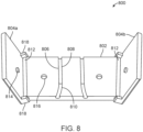
- Figs. 8-13 show an example of another catheter or guidewire management device 800.
- Fig. 8 shows the management device 800 having a lower plate 802 and an upper plate that is formed from two separate upper plate portions 804a, 804b that pivot independently of one another.
- the upper plate portions 804a, 804b are pivotably coupled to the lower plate 802 via hinges 812.
- the lower plate includes two grooves 806 that are sized to hold a guidewire or catheter.
- the grooves 806 on one end of the lower plate are substantially parallel 808 to one another, while on the opposite end the groves flare 810 away from one another.
- the flared end may face the operator and the parallel grooved end may face the patient, or the opposite orientation may be used where the flared end may face the patient and the parallel grooved end may face the operator.
- the bottom plate there are two grooves in the bottom plate, and they may be any size but may be greater than 180 degrees of the circumference of the catheter or guidewire but less than 360 degrees.
- a catheter or guidewire is disposed in the groove 806, a portion is raised above the upper surface lower plate.
- the upper and lower plates sandwich the catheter or guidewire holding the catheter or guidewire in position and preventing axial movement.
- the grooves 808 that are substantially parallel to one another may be distal of the operator and closest to the patient so that the catheters or guidewires enter the patient in substantially parallel direction.
- the flared grooves 810 may be closest to the operator and prevent entanglement and allow easy separation and identification of the proximal ends of the catheters or guidewires.
- the lower plate 802 includes alignment holes 816 which are sized to receive the pins 814 protruding out of the lower surface of the top plate 804a, 804b.
- the position of the pins and alignment holes may also be reversed or used in any permutation or combination.
- the upper plates 804a, 804b are substantially flat and planar plates with two arms 818 that extend from opposite sides of the upper plates 804a, 804b on one end of the upper plates 804a, 804b. These arms 818 receive a pin that protrudes from the sides of the lower plate allowing the upper plates 804a, 804b to pivot open and closed. When closing, the upper plates pivot inward toward the midline of the lower plate and toward one another, and when opening the upper plates pivot outward away from one another and away from the midline. Both upper plates 804a, 804b are open in Fig. 8 .
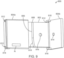
- Fig. 9 shows the device 800 seen in Fig. 8 , but this time with the right upper plate 804b open, and the left upper plate 804a closed thereby obstructing view of the one of the grooves in the lower plate while the other is exposed.
- Other aspects of Fig. 9 are generally the same as disclosed with respect to Fig. 8 .
- Fig. 9 also shows that any marking or indicia N may be applied to any portion of the device 800 in order to help an operator identify catheters or guidewires disposed in the grooves.
- Fig. 10 shows a side view of the catheter or guidewire management device 800 with both upper plates closed against the lower plate. The view shows the grooves exiting the end of the device in a generally parallel direction relative to one another. Both upper plate portions 804a, 804b are closed and abut with the lower plate 802. Other aspects of Fig. 10 are substantially the same as in Fig. 9 .
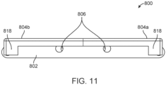
- Fig. 11 shows the same device 800 as in Fig. 10 but is a side view of the device from the end opposite the end seen in Fig. 10 . Thus, in this view the grooves 806 exit the device and flare away from one another. Other aspects of the device 800 in Fig. 11 are generally the same as in Fig. 9 above.
- Fig. 12 shows an exploded view of the catheter or guidewire management device 800 shown in Figs. 8-11 above.
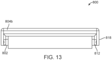
- Fig. 13 shows an end view of the catheter or guidewire management device 800 from a lateral end of the device and shows the upper plate 804b closed and disposed against the lower plate 802. Other aspects of Fig. 13 are substantially the same as shown in Figs. 8011 above.
Landscapes
- Health & Medical Sciences (AREA)
- Life Sciences & Earth Sciences (AREA)
- Biophysics (AREA)
- Pulmonology (AREA)
- Engineering & Computer Science (AREA)
- Anesthesiology (AREA)
- Biomedical Technology (AREA)
- Heart & Thoracic Surgery (AREA)
- Hematology (AREA)
- Animal Behavior & Ethology (AREA)
- General Health & Medical Sciences (AREA)
- Public Health (AREA)
- Veterinary Medicine (AREA)
- Media Introduction/Drainage Providing Device (AREA)
Claims (14)
- Eine Führungsdraht- oder Katheterschaft-Managementvorrichtung, wobei die Vorrichtung Folgendes umfasst:eine obere Platte (120); undeine untere Platte (102) mit mindestens einer darin angeordneten unteren Rille (110), wobei die mindestens eine untere Rille (110) in der unteren Platte zum Aufnehmen des Führungsdrahts oder Katheters dimensioniert ist,wobei die obere Platte (120) lösbar mit der unteren Platte (102) gekoppelt ist und wobei der Führungsdraht oder Katheter zwischen der oberen Platte und der unteren Platte festgehalten wird,wobei die obere Platte (120) ferner mindestens eine darin angeordnete obere Rille (124) umfasst, wobei die mindestens eine obere Rille zum Aufnehmen des Führungsdrahts oder Katheterschafts dimensioniert ist,wobei die mindestens eine untere Rille (110) in der unteren Platte mit der mindestens einen oberen Rille (124) in der oberen Platte zusammenwirkt, um einen Kanal (126) zu bilden, der dazu ausgelegt ist, den Führungsdraht oder Katheterschaft zu halten,wobei die obere Platte (120) und die untere Platte (102) so ausgelegt sind, dass die obere Platte (120) von der unteren Platte (102) abgehoben werden kann, um Zugriff auf einen in einem genannten Kanal (126) aufgenommenen Führungsdraht oder Katheterschaft zu ermöglichen,wobei die mindestens eine untere Rille (110) eine erste untere Rille und eine zweite untere Rille, die in der unteren Platte angeordnet sind, umfasst, wobei sich die erste und zweite untere Rille (110) von einem ersten Rand der unteren Platte (102) zu einem zweiten Rand der unteren Platte, der dem ersten Rand gegenüberliegt, erstrecken und wobei die erste und zweite untere Rille neben dem ersten Rand im Wesentlichen parallel zueinander sind und wobei sich die erste und zweite untere Rille neben dem zweiten Rand voneinander weg aufweiten.
- Vorrichtung nach Anspruch 1, die ferner eine oder mehrere Stifte (110a) umfasst, wobei der eine oder die mehreren Stifte (110a) mit der oberen Platte (120) oder der unteren Platte (102) gekoppelt sind, und wobei die andere von der oberen Platte oder der unteren Platte ferner eine oder mehrere Öffnungen (122) zum Aufnehmen des einen oder der mehreren Stifte (110a) umfasst, um die obere und untere Platte miteinander auszurichten.
- Vorrichtung nach einem der Ansprüche 1 bis 2, wobei die Rillen entweder:kleiner als die Hälfte des Durchmessers des Katheterschafts oder Führungsdrahts sind, um den Führungsdraht oder Katheterschaft in dem Kanal (126) festzuhalten, um eine axiale Bewegung des Katheterschafts oder Führungsdrahts zu verhindern; oderdie Rillen (110; 124) größer als die Hälfte des Durchmessers des Führungsdrahts oder Katheterschafts sind, um eine gleitende Bewegung zu ermöglichen, wenn die zwei Platten aneinander gekoppelt sind.
- Vorrichtung nach einem der Ansprüche 1 bis 3, wobei jede Rille (124) in der oberen oder unteren Platte (120 oder 102) bogenförmig ist.
- Vorrichtung nach einem der Ansprüche 1 bis 4, die ferner eine Seitenwand (112) umfasst, die sich von einer Seite der unteren Platte (102) erstreckt, wobei die Seitenwand einen Anschlag zur Erleichterung der Ausrichtung der oberen Platte (120) mit der unterem Platte und zum Verhindern einer lateralen Bewegung der oberen Platte relativ zu der unteren Platte bereitstellt.
- Vorrichtung nach Anspruch 1, wobei die untere Platte (102) eine flache planare Platte mit zwei linearen lateralen Seiten (104) ist, wobei der erste Rand ein bogenförmiger distaler Rand (108) ist und der zweite Rand ein linearer proximaler Rand (106) ist, wobei die mindestens eine untere Rille (110) zwei bogenförmige Rillen umfasst, wobei an einem Ende der Platte (102) die Rillen (110) aneinander angrenzen und im Wesentlichen parallel zueinander sind und an dem gegenüberliegenden Ende der Platte die Rillen (110) auseinanderlaufen,wobei sich auf jeder der lateralen Seiten eine Wand (112) vertikal von der oberen Oberfläche der unteren Platte (102) weg erstreckt, wobei die Wände als Ausrichtungselemente dienen, um bei der Ausrichtung der oberen Platte (120) mit der unteren Platte (102) zu helfen, wenn die zwei Platten aneinander gekoppelt sind,wobei die obere Platte (120) auch eine flache planare Platte ist und eine Gestalt aufweist, die der Gestalt der unteren Platte (102) entspricht, wobei die obere und untere Platte Ausrichtungsstifte (110a) und Öffnungen (122) aufweisen, wobei jeder Ausrichtungsstift (110a), wenn die zwei Platten aufeinander gestapelt werden, in einer entsprechenden Öffnung aufgenommen wird,wobei jeder Kanal (126) dazu dimensioniert ist, einen Führungsdraht oder Katheterschaft aufzunehmen und ihn zu halten, um eine Verwicklung zu verhindern, während es einem Benutzer gleichzeitig ermöglicht wird, den Draht oder Schaft gleitend zu bewegen oder drehen, während sich dieser in der Managementvorrichtung befindet, oder wenn die Platten in der Managementvorrichtung voneinander getrennt sind.
- Vorrichtung nach einem der vorhergehenden Ansprüche, wobei die obere und untere Platte (120 und 102) so dimensioniert und gestaltet sind, dass sie in die Hand eines Benutzers passen, um gehalten und manipuliert werden zu können.
- Vorrichtung nach einem der vorhergehenden Ansprüche, wobei die obere und untere Platte (120 und 102) starr, weich, biegsam oder elastisch sind.
- Vorrichtung nach einem der vorhergehenden Ansprüche, wobei die obere Platte (120), die untere Platte (102) oder die Rillen (110; 124) eine Materialauskleidung einschließen, um eine reibungsarme Oberfläche bereitzustellen, gegen die der Katheterschaft oder Führungsdraht gleiten kann und gedreht werden kann.
- Vorrichtung nach einem der vorhergehenden Ansprüche, die ferner ein Greifelement (718; 720) umfasst, das mit einer unteren Oberfläche der unteren Platte (102) gekoppelt ist, wobei das Greifelement so dimensioniert und gestaltet ist, dass es das Greifen und Manipulieren der Vorrichtung mit der Hand eines Benutzers erleichtert.
- Vorrichtung nach Anspruch 10, wobei das Greifelement einen Kreisring (718) umfasst, der mit der unteren Oberfläche der unteren Platte gekoppelt ist, wobei der Ring so dimensioniert ist, dass ein Benutzer einen Finger in den Kreisring (718) hineinschieben kann.
- Vorrichtung nach Anspruch 10, wobei das Greifelement ein ausziehbares und zusammenfaltbares Halteelement (720) umfasst.
- Vorrichtung nach einem der vorhergehenden Ansprüche, die ferner Kennzeichner auf der oberen Platte (120) oder der unteren Platte (102) umfasst, um die Identifikation des Führungsdrahts oder Katheterschafts zu erleichtern, der in einer genannten einen Rille (110) der unteren Platte (102) angeordnet ist.
- Ein Verfahren zum Management eines Führungsdrahts oder Katheterschafts, wobei das Verfahren Folgendes umfasst:Bereitstellen einer Führungsdraht- oder Katheterschaft-Managementvorrichtung nach einem der vorhergehenden Ansprüche;Anordnen des Führungsdrahts oder Katheterschafts in einer Rille (110) in der unteren Platte (102); undAuflegen der oberen Platte (120) auf die untere Platte (102), wodurch die der Führungsdraht oder Katheterschaft dazwischen festgehalten werden und ihre Bewegung eingeschränkt wird.
Priority Applications (1)
| Application Number | Priority Date | Filing Date | Title |
|---|---|---|---|
| EP25155778.1A EP4523728A3 (de) | 2019-08-21 | 2020-08-19 | Katheterverwaltungsvorrichtung |
Applications Claiming Priority (2)
| Application Number | Priority Date | Filing Date | Title |
|---|---|---|---|
| US201962889667P | 2019-08-21 | 2019-08-21 | |
| PCT/US2020/046953 WO2021034909A2 (en) | 2019-08-21 | 2020-08-19 | Catheter management device |
Related Child Applications (2)
| Application Number | Title | Priority Date | Filing Date |
|---|---|---|---|
| EP25155778.1A Division EP4523728A3 (de) | 2019-08-21 | 2020-08-19 | Katheterverwaltungsvorrichtung |
| EP25155778.1A Division-Into EP4523728A3 (de) | 2019-08-21 | 2020-08-19 | Katheterverwaltungsvorrichtung |
Publications (3)
| Publication Number | Publication Date |
|---|---|
| EP4017569A2 EP4017569A2 (de) | 2022-06-29 |
| EP4017569A4 EP4017569A4 (de) | 2023-10-18 |
| EP4017569B1 true EP4017569B1 (de) | 2025-04-23 |
Family
ID=74646532
Family Applications (2)
| Application Number | Title | Priority Date | Filing Date |
|---|---|---|---|
| EP20855500.3A Active EP4017569B1 (de) | 2019-08-21 | 2020-08-19 | Katheterverwaltungsvorrichtung |
| EP25155778.1A Pending EP4523728A3 (de) | 2019-08-21 | 2020-08-19 | Katheterverwaltungsvorrichtung |
Family Applications After (1)
| Application Number | Title | Priority Date | Filing Date |
|---|---|---|---|
| EP25155778.1A Pending EP4523728A3 (de) | 2019-08-21 | 2020-08-19 | Katheterverwaltungsvorrichtung |
Country Status (4)
| Country | Link |
|---|---|
| US (3) | US11324925B2 (de) |
| EP (2) | EP4017569B1 (de) |
| CN (1) | CN114269415A (de) |
| WO (1) | WO2021034909A2 (de) |
Families Citing this family (5)
| Publication number | Priority date | Publication date | Assignee | Title |
|---|---|---|---|---|
| US11389621B2 (en) * | 2017-08-10 | 2022-07-19 | Tension Square, Llc | Catheter anchor system and method thereof |
| US11324925B2 (en) | 2019-08-21 | 2022-05-10 | Advanced Bifurcation Systems Inc. | Catheter management device |
| WO2022056376A1 (en) * | 2020-09-11 | 2022-03-17 | Medicametrix, Inc. | Infusion site retainer for maintaining infusion tubing |
| USD1054020S1 (en) | 2022-02-01 | 2024-12-10 | Tension Square, Llc | Catheter anchor system |
| USD1050425S1 (en) | 2022-04-06 | 2024-11-05 | Tension Square, Llc | Catheter anchor system |
Citations (2)
| Publication number | Priority date | Publication date | Assignee | Title |
|---|---|---|---|---|
| CN106267527A (zh) * | 2016-08-11 | 2017-01-04 | 四川众药业有限公司 | 一种血液导管固定装置 |
| US20180280662A1 (en) * | 2014-09-22 | 2018-10-04 | Indiana University Research And Technology Corporation | Tube securing device |
Family Cites Families (20)
| Publication number | Priority date | Publication date | Assignee | Title |
|---|---|---|---|---|
| US4405312A (en) * | 1981-08-31 | 1983-09-20 | Abbott Laboratories | Connecting device for medical liquid containers |
| US5382239A (en) * | 1992-04-24 | 1995-01-17 | Becton, Dickinson And Company | Repositional catheter fixation device |
| US5389082A (en) * | 1994-03-14 | 1995-02-14 | Baugues; Mary C. | Intravenous line separator system |
| US6283945B1 (en) * | 1997-10-17 | 2001-09-04 | Venetec International, Inc. | Anchoring system for a medical article |
| US6572588B1 (en) * | 2000-03-10 | 2003-06-03 | Venetec International, Inc. | Medical anchoring system |
| WO2003092781A2 (en) * | 2002-05-01 | 2003-11-13 | Venetec International, Inc. | Medical line securement device |
| JP4115963B2 (ja) * | 2004-05-12 | 2008-07-09 | ポップリベット・ファスナー株式会社 | パイプ等のクランプ装置 |
| US7457506B1 (en) * | 2005-12-30 | 2008-11-25 | Osborne Orthopedic Group, Inc. | Line organizer |
| WO2010002393A1 (en) | 2008-06-30 | 2010-01-07 | Venetec International, Inc. | Anchoring system for a medical article |
| US20100006738A1 (en) * | 2008-07-08 | 2010-01-14 | Teirstein Paul S | Guide wire and catheter management device |
| WO2011033939A1 (ja) * | 2009-09-16 | 2011-03-24 | テルモ株式会社 | カテーテルホルダ |
| KR101135203B1 (ko) | 2009-12-18 | 2012-04-16 | 이창윤 | 의료용관 고정클립 |
| JP5602460B2 (ja) * | 2010-03-05 | 2014-10-08 | 株式会社ニフコ | クランプ |
| JP5818614B2 (ja) * | 2011-09-28 | 2015-11-18 | 日本コヴィディエン株式会社 | カテーテル固定具 |
| WO2013116298A1 (en) * | 2012-01-30 | 2013-08-08 | Volcano Corporation | Elongated endoluminal device packaging system and method |
| US9400431B2 (en) * | 2013-12-23 | 2016-07-26 | United Microelectronics Corp. | Supporting assembly with a rolling ball disposed directly below supporting rods and method for using the same |
| US20170333680A1 (en) * | 2016-05-23 | 2017-11-23 | Anthony Bentley | Central venous catheter hub cocoon |
| KR102010491B1 (ko) * | 2017-04-03 | 2019-08-13 | 아이메디컴(주) | 조종 가능한 카테터 |
| US20190217076A1 (en) * | 2018-01-17 | 2019-07-18 | Terrence Jay O'Neil | Systems, Devices, and/or Methods for Managing Medical Treatments |
| US11324925B2 (en) | 2019-08-21 | 2022-05-10 | Advanced Bifurcation Systems Inc. | Catheter management device |
-
2020
- 2020-08-19 US US16/997,119 patent/US11324925B2/en active Active
- 2020-08-19 EP EP20855500.3A patent/EP4017569B1/de active Active
- 2020-08-19 CN CN202080058739.1A patent/CN114269415A/zh active Pending
- 2020-08-19 EP EP25155778.1A patent/EP4523728A3/de active Pending
- 2020-08-19 WO PCT/US2020/046953 patent/WO2021034909A2/en not_active Ceased
-
2022
- 2022-04-07 US US17/715,630 patent/US12239802B2/en active Active
-
2025
- 2025-01-28 US US19/038,881 patent/US20250170368A1/en active Pending
Patent Citations (2)
| Publication number | Priority date | Publication date | Assignee | Title |
|---|---|---|---|---|
| US20180280662A1 (en) * | 2014-09-22 | 2018-10-04 | Indiana University Research And Technology Corporation | Tube securing device |
| CN106267527A (zh) * | 2016-08-11 | 2017-01-04 | 四川众药业有限公司 | 一种血液导管固定装置 |
Also Published As
| Publication number | Publication date |
|---|---|
| EP4523728A2 (de) | 2025-03-19 |
| WO2021034909A3 (en) | 2021-04-01 |
| US11324925B2 (en) | 2022-05-10 |
| WO2021034909A2 (en) | 2021-02-25 |
| CN114269415A (zh) | 2022-04-01 |
| US20250170368A1 (en) | 2025-05-29 |
| EP4523728A3 (de) | 2025-06-11 |
| US20220226612A1 (en) | 2022-07-21 |
| US12239802B2 (en) | 2025-03-04 |
| EP4017569A2 (de) | 2022-06-29 |
| US20210052856A1 (en) | 2021-02-25 |
| EP4017569A4 (de) | 2023-10-18 |
Similar Documents
| Publication | Publication Date | Title |
|---|---|---|
| EP4017569B1 (de) | Katheterverwaltungsvorrichtung | |
| US7951092B2 (en) | Guidewire loader apparatus and method | |
| US20250387115A1 (en) | Endoscopic suturing system having external instrument channel | |
| US20190059904A1 (en) | Endoscopic clip applier | |
| US10667813B2 (en) | Adapter with centering mechanism for articulation joint | |
| US20200146687A1 (en) | Articulating clip applier | |
| US8961542B2 (en) | Articulating clip applier cartridge | |
| US6986780B2 (en) | Surgical element delivery system and method | |
| US7828807B2 (en) | Implantation of a deformable prosthesic device | |
| US20070270811A1 (en) | Reducing device | |
| US20100268254A1 (en) | Clamp System and Method of Using the Same | |
| US10226596B1 (en) | Catheter and guidewire advancement device | |
| JP2020528776A (ja) | 内視鏡バスケット送達カテーテル | |
| US10945756B2 (en) | Device of inserting and controlling a snare | |
| RU2489102C2 (ru) | Устройство для прикрепления протеза к сосуду | |
| US11090462B2 (en) | Advancement or retraction device | |
| US12035934B2 (en) | Control mechanism for end effectors and method of use | |
| US20250312061A1 (en) | Arthroscopic Cannula and Insertion Tool | |
| WO2018053633A1 (en) | Catheter advancement device |
Legal Events
| Date | Code | Title | Description |
|---|---|---|---|
| STAA | Information on the status of an ep patent application or granted ep patent |
Free format text: STATUS: THE INTERNATIONAL PUBLICATION HAS BEEN MADE |
|
| PUAI | Public reference made under article 153(3) epc to a published international application that has entered the european phase |
Free format text: ORIGINAL CODE: 0009012 |
|
| STAA | Information on the status of an ep patent application or granted ep patent |
Free format text: STATUS: REQUEST FOR EXAMINATION WAS MADE |
|
| 17P | Request for examination filed |
Effective date: 20220302 |
|
| AK | Designated contracting states |
Kind code of ref document: A2 Designated state(s): AL AT BE BG CH CY CZ DE DK EE ES FI FR GB GR HR HU IE IS IT LI LT LU LV MC MK MT NL NO PL PT RO RS SE SI SK SM TR |
|
| DAV | Request for validation of the european patent (deleted) | ||
| DAX | Request for extension of the european patent (deleted) | ||
| REG | Reference to a national code |
Ref legal event code: R079 Ipc: A61M0025020000 Ref country code: DE Ref legal event code: R079 Ref document number: 602020050126 Country of ref document: DE Free format text: PREVIOUS MAIN CLASS: A61M0025000000 Ipc: A61M0025020000 |
|
| A4 | Supplementary search report drawn up and despatched |
Effective date: 20230919 |
|
| RIC1 | Information provided on ipc code assigned before grant |
Ipc: A61M 25/00 20060101ALN20230913BHEP Ipc: A61M 25/02 20060101AFI20230913BHEP |
|
| STAA | Information on the status of an ep patent application or granted ep patent |
Free format text: STATUS: EXAMINATION IS IN PROGRESS |
|
| 17Q | First examination report despatched |
Effective date: 20240510 |
|
| GRAP | Despatch of communication of intention to grant a patent |
Free format text: ORIGINAL CODE: EPIDOSNIGR1 |
|
| STAA | Information on the status of an ep patent application or granted ep patent |
Free format text: STATUS: GRANT OF PATENT IS INTENDED |
|
| RIC1 | Information provided on ipc code assigned before grant |
Ipc: A61M 25/00 20060101ALN20241108BHEP Ipc: A61M 25/02 20060101AFI20241108BHEP |
|
| INTG | Intention to grant announced |
Effective date: 20241120 |
|
| GRAS | Grant fee paid |
Free format text: ORIGINAL CODE: EPIDOSNIGR3 |
|
| GRAA | (expected) grant |
Free format text: ORIGINAL CODE: 0009210 |
|
| STAA | Information on the status of an ep patent application or granted ep patent |
Free format text: STATUS: THE PATENT HAS BEEN GRANTED |
|
| AK | Designated contracting states |
Kind code of ref document: B1 Designated state(s): AL AT BE BG CH CY CZ DE DK EE ES FI FR GB GR HR HU IE IS IT LI LT LU LV MC MK MT NL NO PL PT RO RS SE SI SK SM TR |
|
| REG | Reference to a national code |
Ref country code: GB Ref legal event code: FG4D |
|
| REG | Reference to a national code |
Ref country code: CH Ref legal event code: EP |
|
| REG | Reference to a national code |
Ref country code: DE Ref legal event code: R096 Ref document number: 602020050126 Country of ref document: DE |
|
| REG | Reference to a national code |
Ref country code: IE Ref legal event code: FG4D |
|
| REG | Reference to a national code |
Ref country code: NL Ref legal event code: MP Effective date: 20250423 |
|
| PG25 | Lapsed in a contracting state [announced via postgrant information from national office to epo] |
Ref country code: NL Free format text: LAPSE BECAUSE OF FAILURE TO SUBMIT A TRANSLATION OF THE DESCRIPTION OR TO PAY THE FEE WITHIN THE PRESCRIBED TIME-LIMIT Effective date: 20250423 |
|
| REG | Reference to a national code |
Ref country code: AT Ref legal event code: MK05 Ref document number: 1787211 Country of ref document: AT Kind code of ref document: T Effective date: 20250423 |
|
| PG25 | Lapsed in a contracting state [announced via postgrant information from national office to epo] |
Ref country code: FI Free format text: LAPSE BECAUSE OF FAILURE TO SUBMIT A TRANSLATION OF THE DESCRIPTION OR TO PAY THE FEE WITHIN THE PRESCRIBED TIME-LIMIT Effective date: 20250423 Ref country code: ES Free format text: LAPSE BECAUSE OF FAILURE TO SUBMIT A TRANSLATION OF THE DESCRIPTION OR TO PAY THE FEE WITHIN THE PRESCRIBED TIME-LIMIT Effective date: 20250423 Ref country code: PT Free format text: LAPSE BECAUSE OF FAILURE TO SUBMIT A TRANSLATION OF THE DESCRIPTION OR TO PAY THE FEE WITHIN THE PRESCRIBED TIME-LIMIT Effective date: 20250825 |
|
| PGFP | Annual fee paid to national office [announced via postgrant information from national office to epo] |
Ref country code: DE Payment date: 20250723 Year of fee payment: 6 |
|
| REG | Reference to a national code |
Ref country code: LT Ref legal event code: MG9D |
|
| PG25 | Lapsed in a contracting state [announced via postgrant information from national office to epo] |
Ref country code: NO Free format text: LAPSE BECAUSE OF FAILURE TO SUBMIT A TRANSLATION OF THE DESCRIPTION OR TO PAY THE FEE WITHIN THE PRESCRIBED TIME-LIMIT Effective date: 20250723 Ref country code: GR Free format text: LAPSE BECAUSE OF FAILURE TO SUBMIT A TRANSLATION OF THE DESCRIPTION OR TO PAY THE FEE WITHIN THE PRESCRIBED TIME-LIMIT Effective date: 20250724 |
|
| PG25 | Lapsed in a contracting state [announced via postgrant information from national office to epo] |
Ref country code: PL Free format text: LAPSE BECAUSE OF FAILURE TO SUBMIT A TRANSLATION OF THE DESCRIPTION OR TO PAY THE FEE WITHIN THE PRESCRIBED TIME-LIMIT Effective date: 20250423 |
|
| PG25 | Lapsed in a contracting state [announced via postgrant information from national office to epo] |
Ref country code: BG Free format text: LAPSE BECAUSE OF FAILURE TO SUBMIT A TRANSLATION OF THE DESCRIPTION OR TO PAY THE FEE WITHIN THE PRESCRIBED TIME-LIMIT Effective date: 20250423 |
|
| PGFP | Annual fee paid to national office [announced via postgrant information from national office to epo] |
Ref country code: GB Payment date: 20250728 Year of fee payment: 6 |
|
| PG25 | Lapsed in a contracting state [announced via postgrant information from national office to epo] |
Ref country code: HR Free format text: LAPSE BECAUSE OF FAILURE TO SUBMIT A TRANSLATION OF THE DESCRIPTION OR TO PAY THE FEE WITHIN THE PRESCRIBED TIME-LIMIT Effective date: 20250423 |
|
| PG25 | Lapsed in a contracting state [announced via postgrant information from national office to epo] |
Ref country code: AT Free format text: LAPSE BECAUSE OF FAILURE TO SUBMIT A TRANSLATION OF THE DESCRIPTION OR TO PAY THE FEE WITHIN THE PRESCRIBED TIME-LIMIT Effective date: 20250423 |
|
| PGFP | Annual fee paid to national office [announced via postgrant information from national office to epo] |
Ref country code: FR Payment date: 20250722 Year of fee payment: 6 |
|
| PG25 | Lapsed in a contracting state [announced via postgrant information from national office to epo] |
Ref country code: RS Free format text: LAPSE BECAUSE OF FAILURE TO SUBMIT A TRANSLATION OF THE DESCRIPTION OR TO PAY THE FEE WITHIN THE PRESCRIBED TIME-LIMIT Effective date: 20250723 |
|
| PG25 | Lapsed in a contracting state [announced via postgrant information from national office to epo] |
Ref country code: IS Free format text: LAPSE BECAUSE OF FAILURE TO SUBMIT A TRANSLATION OF THE DESCRIPTION OR TO PAY THE FEE WITHIN THE PRESCRIBED TIME-LIMIT Effective date: 20250823 |
|
| PG25 | Lapsed in a contracting state [announced via postgrant information from national office to epo] |
Ref country code: LV Free format text: LAPSE BECAUSE OF FAILURE TO SUBMIT A TRANSLATION OF THE DESCRIPTION OR TO PAY THE FEE WITHIN THE PRESCRIBED TIME-LIMIT Effective date: 20250423 |
|
| PG25 | Lapsed in a contracting state [announced via postgrant information from national office to epo] |
Ref country code: DK Free format text: LAPSE BECAUSE OF FAILURE TO SUBMIT A TRANSLATION OF THE DESCRIPTION OR TO PAY THE FEE WITHIN THE PRESCRIBED TIME-LIMIT Effective date: 20250423 Ref country code: SM Free format text: LAPSE BECAUSE OF FAILURE TO SUBMIT A TRANSLATION OF THE DESCRIPTION OR TO PAY THE FEE WITHIN THE PRESCRIBED TIME-LIMIT Effective date: 20250423 |
|
| PG25 | Lapsed in a contracting state [announced via postgrant information from national office to epo] |
Ref country code: CZ Free format text: LAPSE BECAUSE OF FAILURE TO SUBMIT A TRANSLATION OF THE DESCRIPTION OR TO PAY THE FEE WITHIN THE PRESCRIBED TIME-LIMIT Effective date: 20250423 |
|
| PG25 | Lapsed in a contracting state [announced via postgrant information from national office to epo] |
Ref country code: EE Free format text: LAPSE BECAUSE OF FAILURE TO SUBMIT A TRANSLATION OF THE DESCRIPTION OR TO PAY THE FEE WITHIN THE PRESCRIBED TIME-LIMIT Effective date: 20250423 |
|
| PG25 | Lapsed in a contracting state [announced via postgrant information from national office to epo] |
Ref country code: RO Free format text: LAPSE BECAUSE OF FAILURE TO SUBMIT A TRANSLATION OF THE DESCRIPTION OR TO PAY THE FEE WITHIN THE PRESCRIBED TIME-LIMIT Effective date: 20250423 Ref country code: SK Free format text: LAPSE BECAUSE OF FAILURE TO SUBMIT A TRANSLATION OF THE DESCRIPTION OR TO PAY THE FEE WITHIN THE PRESCRIBED TIME-LIMIT Effective date: 20250423 |
|
| PG25 | Lapsed in a contracting state [announced via postgrant information from national office to epo] |
Ref country code: IT Free format text: LAPSE BECAUSE OF FAILURE TO SUBMIT A TRANSLATION OF THE DESCRIPTION OR TO PAY THE FEE WITHIN THE PRESCRIBED TIME-LIMIT Effective date: 20250423 |