EP4016882A1 - Wavelength division multiplexing system, local apparatus, and remote apparatus - Google Patents
Wavelength division multiplexing system, local apparatus, and remote apparatus Download PDFInfo
- Publication number
- EP4016882A1 EP4016882A1 EP20855067.3A EP20855067A EP4016882A1 EP 4016882 A1 EP4016882 A1 EP 4016882A1 EP 20855067 A EP20855067 A EP 20855067A EP 4016882 A1 EP4016882 A1 EP 4016882A1
- Authority
- EP
- European Patent Office
- Prior art keywords
- optical
- demultiplexer
- wdm
- optical modules
- central wavelengths
- Prior art date
- Legal status (The legal status is an assumption and is not a legal conclusion. Google has not performed a legal analysis and makes no representation as to the accuracy of the status listed.)
- Granted
Links
Images
Classifications
-
- H—ELECTRICITY
- H04—ELECTRIC COMMUNICATION TECHNIQUE
- H04Q—SELECTING
- H04Q11/00—Selecting arrangements for multiplex systems
- H04Q11/0001—Selecting arrangements for multiplex systems using optical switching
- H04Q11/0062—Network aspects
-
- H—ELECTRICITY
- H04—ELECTRIC COMMUNICATION TECHNIQUE
- H04J—MULTIPLEX COMMUNICATION
- H04J14/00—Optical multiplex systems
- H04J14/02—Wavelength-division multiplex systems
- H04J14/0227—Operation, administration, maintenance or provisioning [OAMP] of WDM networks, e.g. media access, routing or wavelength allocation
- H04J14/0254—Optical medium access
- H04J14/0256—Optical medium access at the optical channel layer
-
- H—ELECTRICITY
- H04—ELECTRIC COMMUNICATION TECHNIQUE
- H04B—TRANSMISSION
- H04B10/00—Transmission systems employing electromagnetic waves other than radio-waves, e.g. infrared, visible or ultraviolet light, or employing corpuscular radiation, e.g. quantum communication
- H04B10/27—Arrangements for networking
-
- H—ELECTRICITY
- H04—ELECTRIC COMMUNICATION TECHNIQUE
- H04B—TRANSMISSION
- H04B10/00—Transmission systems employing electromagnetic waves other than radio-waves, e.g. infrared, visible or ultraviolet light, or employing corpuscular radiation, e.g. quantum communication
- H04B10/40—Transceivers
-
- H—ELECTRICITY
- H04—ELECTRIC COMMUNICATION TECHNIQUE
- H04B—TRANSMISSION
- H04B10/00—Transmission systems employing electromagnetic waves other than radio-waves, e.g. infrared, visible or ultraviolet light, or employing corpuscular radiation, e.g. quantum communication
- H04B10/50—Transmitters
- H04B10/572—Wavelength control
Definitions
- the present disclosure relates to the field of communication technology, in particular to a Wavelength Division Multiplexing (WDM) system, an equipment at central office and an equipment at remote side.
- WDM Wavelength Division Multiplexing
- AAUs Active Antenna Units
- each AAU is provided with two 25G optical modules at a spectrum of 160M
- a 120-core optical fiber needs to be provided for 10 physical base stations in the case of a two-fiber bidirectional optical fiber direct-drive scheme, which has presented a huge challenge to an optical fiber resources of the fronthaul network.
- DWDM Dense Wavelength Division Multiplexing
- CWDM Coarse Wavelength Division Multiplexing
- LAN-WDM Local Area Network Wavelength Division Multiplexing
- a band range for the DWDM covers a conventional band, i.e., C band, and a long band, i.e., L band, with an integral multiple of 12.5GHz as a channel spacing.
- C band a conventional band
- L band a long band
- 12.5GHz a channel spacing
- a commonly-used DWDM is mainly based on C-band 50GHz and 100GHz 80-wavelength or 40-wavelength channels.
- the CWDM has a band range from 1271nm to 1611nm, it totally includes 18 channels at different wavelengths with a channel spacing of 20nm between adjacent channels.
- the LAN-WDM has a band range covering 1273.54nm to 1286.66nm and 1295.56nm to 1309.14nm in an original band, i.e., O band, and it totally includes 8 channels at different wavelengths with a channel spacing of 800GHz.
- An object of the present disclosure is to provide a WDM system, an equipment at central office and an equipment at remote side, so as to solve the problem that it is impossible for the related WDM technology to meet a system requirement on the 5G fronthaul network.
- the present disclosure provides in some embodiments a WDM system, including optical modules, and a pair of WDM multiplexer/demultiplexer, wherein the optical modules are connected to the WDM multiplexer/demultiplexer, and the pair of WDM multiplexer/demultiplexer are connected to each other through an optical fiber link;
- the central wavelengths of the optical modules are determined by adjusting and shifting the equal-spacing central wavelengths, respectively.
- the central wavelengths of the transmitting optical signals for the optical modules located at adjacent wavelength channels are symmetrical with a boundary of the adjacent channels of the WDM multiplexer/demultiplexer.
- the spacing between the central wavelengths of the transmitting optical signals for the optical modules located at the odd wavelength channels is 2M;
- the channel bandwidths of each channels for the WDM multiplexer/demultiplexer are less than or equal to M, and the center of the channel bandwidth is located at the same or different point with the center of the channel.
- a laser in the optical module is a Direct Modulated Laser (DML) or an Electro-absorption Modulated Laser (EML).
- DML Direct Modulated Laser
- EML Electro-absorption Modulated Laser
- the optical fiber link is a single-fiber unidirectional optical fiber link or a single-fiber bidirectional optical fiber link.
- the present disclosure provides in some embodiments an equipment at central office, comprising optical modules and a WDM multiplexer/demultiplexer, wherein the optical modules are connected to the WDM multiplexer/demultiplexer, respectively;
- the central wavelengths of the optical modules are determined by adjusting and shifting the equal-spacing central wavelengths, respectively.
- a spacing between the central wavelength of the transmitting optical signals for the optical modules and the boundary of the adjacent channels of the WDM multiplexer/demultiplexer is N or (M-N), wherein M represents the channel spacing of the WDM multiplexer/demultiplexer, and N represents the adjusting and shifting value of the central wavelengths of the transmitting optical signals for the optical modules.
- the channel bandwidths of each channels for the WDM multiplexer/demultiplexer are less than or equal to M, and the center of the channel bandwidth is located at the same or different point with the center of the channel.
- a laser in the optical module is a DML or an EML.
- the optical module is deployed in an Optical Transport Network (OTN) or WDM equipment.
- OTN Optical Transport Network
- WDM Wideband Division Multiple Access
- the present disclosure provides in some embodiments an equipment at remote side, including optical modules and a WDM multiplexer/demultiplexer, wherein the optical modules are connected to the WDM multiplexer/demultiplexer;
- the central wavelengths of the optical modules are determined by adjusting and shifting the equal-spacing central wavelengths, respectively.
- a spacing between the central wavelength of the transmitting optical signals for the optical modules and the boundary of the adjacent channels of the WDM multiplexer/demultiplexer is N or (M-N), wherein M represents the channel spacing of the WDM multiplexer/demultiplexer, and N represents the adjusting and shifting value of the central wavelengths of the transmitting optical signals for the optical modules.
- the channel bandwidths of each channels for the WDM multiplexer/demultiplexer are less than or equal to M, and the center of the channel bandwidth is located at the same or different point with the center of the channel.
- a laser in the optical module is a DML or an EML.
- each optical module is deployed in an Active Antenna Unit (AAU) or a Remote Radio Unit (RRU).
- AAU Active Antenna Unit
- RRU Remote Radio Unit
- the optical module in the equipment at remote side is managed by an optical module in an equipment at central office; or the optical module in the equipment at remote side is managed by an OTN or WDM equipment where the optical module in the equipment at central office is deployed
- the optical modules having wavelength channels with different spacings and the WDM multiplexer/demultiplexer having wavelength channels with a same spacing are adopted, and the central wavelengths of the optical modules are determined by adjusting and shifting the equal-spacing central wavelengths. As a result, it is able to rapidly meet the system requirement on a 5G fronthaul network.
- a 10G DWDM optical module and a WDM multiplexer/demultiplexer have been applied to a 10G OTN, so as to support the transmission of a 40-wavelength signal with a channel spacing of 50GHz and an 80-wavelength signal with a channel spacing of 100GH in a C band.
- M-D WDM multiplexer/demultiplexer
- TEC Thermo Electric Cooler Due to a dispersion penalty in the C band, an EML also needs to be adopted. In this regard, a system cost increases significantly.
- 25G optical modules at a wavelength of 1271nm, 1291nm, 1311nm or 1331nm have been widely applied to such a scenario as data center 100GE.
- 25G optical modules at a wavelength of 1351nm or 1371nm have been provided in small batch. Due to a dispersion effect of the optical fiber, the EML needs to be adopted by 6-wavelength 25G CWDM optical modules at wavelengths of 1471nm to 1571nm, so the manufacture cost increases significantly to be approximately equal to the cost of the DWDM optical module. There is currently no CWDM product for the other bands.
- LAN-WDM For an LAN-WDM technology, 8 wavelength channels are all located within an O band, so there is an advantage that the dispersion penalty is small.
- 25G LAN-WDM optical modules include the EML, so the manufacture cost is relatively high.
- the LAN-WDM merely supports 8 wavelengths, so it is impossible to meet the requirement on 12 wavelengths for a 5G fronthaul network.
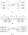
- the present disclosure provides in some embodiments a WDM system 10, which includes optical modules, and a pair of WDM multiplexer/demultiplexer.
- the plurality of optical modules are connected to the respective two WDM multiplexer/demultiplexer 12, the pair of WDM multiplexer/demultiplexer are connected to each other through an optical fiber link 13.
- the optical fiber link 13 may be a single-fiber unidirectional optical fiber link or a single-fiber bidirectional optical fiber link, i.e., the WDM system 10 may be a single-fiber unidirectional WDM system or a single-fiber bidirectional WDM system.
- the optical module 11 is configured to perform conversion between an electric signal and an optical signal using a photovoltaic conversion method in the related art, which will not be particularly defined herein.
- the WDM multiplexer/demultiplexer 12 may receive a plurality of optical signals at different wavelengths from the optical module 11 and multiplex the optical signals. In addition, the WDM multiplexer/demultiplexer 12 may demultiplex the multiplexed optical signal and transmit the optical signals at different wavelengths to a corresponding optical module 11.
- the WDM multiplexer/demultiplexer 12 may include a multiplexer and a demultiplexer formed integrally or formed in a separated manner, which will not be particularly defined herein.
- the WDM multiplexer/demultiplexer 12 may be a thin film filer or an Arrayed Waveguide Grating (AWG), and a specific type of the WDM multiplexer/demultiplexer 12 will not be particularly defined herein.
- AMG Arrayed Waveguide Grating
- Fig. 1 merely shows a scenario where the WDM multiplexer/demultiplexer 12 is connected to three optical modules 11.
- the quantity of optical modules 11 may be adjusted according to the practical need.
- the quantity of optical modules 11 connected to the WDM multiplexer/demultiplexer 12 will not be particularly defined herein.
- spacings between central wavelengths of channels for the WDM multiplexer/demultiplexer 12 are equal; spacings between central wavelengths of transmitting optical signals for the optical modules 11 located at adjacent wavelength channels are unequal; spacings between the central wavelengths of the transmitting optical signals for the optical modules 11 located at odd wavelength channels are equal; spacings between the central wavelengths of the transmitting optical signals for the optical modules 11 located at even wavelength channels are equal.
- the optical modules 11 having wavelength channels with different spacings and the WDM multiplexer/demultiplexer 12 having wavelength channels with a same spacing are adopted in the WDM system 10.
- the central wavelengths of the plurality of optical modules 11 are determined by adjusting and shifting the equal-spacing central wavelengths, respectively. For example, on the basis of first 6 wavelengths in the CWDM technology, i.e., 1271nm to 1371nm, the central wavelengths of the optical modules are shifted to the left and right by 3.5nm, so as to obtain 12 central wavelengths with different spacings for the WDM system, thereby to meet the requirement on the 12 wavelengths for a 5G fronthaul network.
- a laser of the optical module 11 is a DML or an EML
- first 6 wavelengths in the CWDM system are adjusted and shifted to obtain a central wavelength of 12 wavelengths with unequal spacings in the WDM system
- the 12 wavelengths are all implemented through the DML with a low cost, so it is able to effectively reduce the overall cost of the system.
- Fig. 2 shows the distribution of the central wavelengths of the optical module 11 in the wavelength channels.
- the central wavelengths of the light beams transmitted by the optical modules 11 in adjacent wavelength channels are symmetric about a boundary between adjacent channels for the WDM multiplexer/demultiplexer 12.
- the channel bandwidths of each channels for the WDM multiplexer/demultiplexer 12 are less than or equal to M, i.e., the channel bandwidth of the WDM multiplexer/demultiplexer 12 is set to be less than or equal to the channel spacing.
- the center of the channel bandwidth is located at the same or different point with the center of the channel, i.e., the center of the channel bandwidth is not limited to be the center of the channel spacing, so that the central wavelengths of the adjacent channels for the WDM multiplexer/demultiplexer have different spacings.
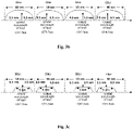
- each channel of the WDM multiplexer/demultiplexer 12 has a channel bandwidth of 10nm (indicated by an arc in Fig. 3b ), which equals to the channel spacing M of the WDM multiplexer/demultiplexer.
- a center of each channel bandwidth is the same as a center of a corresponding channel.
- each channel of the WDM multiplexer/demultiplexer 12 has a channel bandwidth of 5nm (indicated by a trapezoid in Fig. 3c ), which is small than the channel spacing M of the WDM multiplexer/demultiplexer 12.
- a center of each channel bandwidth is different from a center of a corresponding channel.
- the central wavelength of the light from each optical module has a corresponding wavelength channel, so it is able to meet the system requirement on the 5G fronthaul network.
- the optical modules having the wavelength channels with different spacings and the WDM multiplexer/demultiplexer having the wavelength channels with a same spacing are adopted, so it is able to meet the system requirement on the 5G fronthaul network.
- two signal interaction ends are a central office end and a remote end.
- a signal may be transmitted from the central office end to the remote end, or from the remote end to the central office end.
- the present disclosure further provides in some embodiments an equipment at central office, which includes optical modules and a WDM multiplexer/demultiplexer.
- the optical modules are connected to the WDM multiplexer/demultiplexer, respectively.
- the description about the optical modules and the WDM multiplexer/demultiplexer may refer to that about the optical module 11 and the WDM multiplexer/demultiplexer 12 in the WDM system 10 in Fig. 1 , and thus will not be particularly defined herein.
- Spacings between central wavelengths of channels for the WDM multiplexer/demultiplexer are equal; spacings between central wavelengths of transmitting optical signals for the optical modules located at adjacent wavelength channels are unequal; spacings between the central wavelengths of the transmitting optical signals for the optical modules located at odd wavelength channels are equal; spacings between the central wavelengths of the transmitting optical signals for the optical modules located at even wavelength channels are equal.
- the central wavelengths of the optical modules are determined by adjusting and shifting the equal-spacing central wavelengths, respectively.
- the distribution of the central wavelengths of the transmitting optical signals for the optical modules may refer to the relevant description in Fig. 2 .
- a spacing between the central wavelength of the transmitting optical signals for the optical modules and the boundary of the adjacent channels of the WDM multiplexer/demultiplexer is N or (M-N), where M represents the channel spacing of the WDM multiplexer/demultiplexer, and N represents the adjusting and shifting value of the central wavelengths of the transmitting optical signals for the optical modules.
- a laser in the optical module is a DML or an EML.
- each optical module of the equipment at central office is deployed in an OTN or WDM equipment.
- the WDM multiplexer/demultiplexer of the equipment at central office may be arranged in the OTN or WDM equipment together with the optical modules, or arranged at another position and connected to the optical modules through an optical fiber.
- the present disclosure further provides in some embodiments an equipment at remote side, which includes optical modules and a WDM multiplexer/demultiplexer.
- the plurality of optical modules is connected to the WDM multiplexer/demultiplexer.
- the description about the optical modules and the WDM multiplexer/demultiplexer may refer to that about the optical modules 11 and the WDM multiplexer/demultiplexer 12 in the WDM system 10 in Fig. 1 , and thus will not be particularly defined herein.
- Spacings between central wavelengths of channels for the WDM multiplexer/demultiplexer are equal; spacings between central wavelengths of transmitting optical signals for the optical modules located at adjacent wavelength channels are unequal; spacings between the central wavelengths of the transmitting optical signals for the optical modules located at odd wavelength channels are equal; spacings between the central wavelengths of the transmitting optical signals for the optical modules located at even wavelength channels are equal.
- the central wavelengths of the optical modules are determined by adjusting and shifting the equal-spacing central wavelengths, respectively.
- the distribution of the central wavelengths of the transmitting optical signals for the optical modules may refer to that in Fig. 2 .
- a spacing between the central wavelength of the transmitting optical signals for the optical modules and the boundary of the adjacent channels of the WDM multiplexer/demultiplexer is N or (M-N), where M represents the channel spacing of the WDM multiplexer/demultiplexer, and N represents the adjusting and shifting value of the central wavelengths of the transmitting optical signals for the optical modules.
- a laser in the optical module is a DML or an EML.
- each optical module of the equipment at remote side is deployed in an AAU or an RRU.
- the WDM multiplexer/demultiplexer of the equipment at remote side may be arranged at a position different from the optical module.
- the WDM multiplexer/demultiplexer may be arranged on a tower of a base station and connected to the optical module in the AAU or RRU through an optical fiber.
- the optical module of the equipment at remote side may be managed by the optical module of the equipment at central office, and when the optical module of the equipment at central office has insufficient performance, the optical module of the equipment at remote side may be managed by the OTN or WDM equipment where the optical module of the equipment at central office is deployed.
- Fig. 3a shows architecture of the WDM system
- Figs. 3b and 3c show the distribution of the central wavelengths of the transmitting optical signals for the optical modules in the channel for the WDM multiplexer/demultiplexer (WM/D).
- the WDM system is a single-fiber bidirectional system.
- the central wavelengths of the channels for the WDM multiplexer/demultiplexer have a same spacing, i.e., 10nm.
- the spacings between central wavelengths of transmitting optical signals for the optical modules located at adjacent wavelength channels are unequal, the spacings between the central wavelengths of the transmitting optical signals for the optical modules located at odd wavelength channels are equal, i.e., 20nm, and spacings between the central wavelengths of the transmitting optical signals for the optical modules located at even wavelength channels are equal, i.e., 20nm.
- a spacing between the central wavelengths of the transmitting optical signals for the optical modules located at adjacent odd wavelength channel and even wavelength channel is 7nm or 13nm.
- the central wavelengths of the transmitting optical signals for the optical modules located at adjacent wavelength channels are symmetrical with a boundary of the adjacent channels of the WDM multiplexer/demultiplexer.
- the central wavelengths of the optical modules are shifted to the left and right by 3.5nm, so as to obtain a central wavelength of 12 wavelengths with different spacings for the WDM system.
- Table 1 shows the allocation of the central wavelengths, where an index number of the channel is merely for illustrative purposes.
- the 12-wavelength optical module and an implementation mode of the wavelengths will not be particularly defined herein.
- Table 1 Index number of channel Central wavelength (nm) 1 1267.5 2 1274.5 3 1287.5 4 1294.5 5 1307.5 6 1314.5 7 1327.5 8 1334.5 9 1347.5 10 1354.5 11 1367.5 12 1374.5
- the optical module for transmitting the light at the central wavelength of 1267.5nm may match the optical module for transmitting the light at the central wavelength of 1274.5nm.
- the optical module for transmitting the light at the central wavelength of 1267.5nm it transmits the light at the wavelength of 1267.5nm and receives the light at the wavelength of 1274.5nm
- the optical module for transmitting the light at the central wavelength of 1274.5nm it transmits the light at the wavelength of 1274.5nm and receives the light at the wavelength of 1267.5nm.
- the same may also be applied to the allocation of the central wavelengths of the light transmitted and received by the other optical modules, which will thus not be particularly defined herein.
- the above matching mode of the central wavelengths is merely for illustrative purposes, and the specific matching mode of the central wavelengths will not be particularly defined herein.
- the cost-effective DML of the 25G CWDM for the first 6 wavelengths is shared, and the 12 wavelengths are all implemented by the DML, so it is able to reduce the manufacture cost, and rapidly meet the 12-wavelength 25G requirement through a mature industry chain.
- the channels of the WDM multiplexer/demultiplexer have a same spacing and the spacing is 10n for easy implementation.
- the dispersion penalty in the C band is large, the EML is adopted, and it is necessary to control the optical module using a precise TEC.
- the 25G DWDM optical module is still in small-batch production.
- the same-spacing WDM system is replaced with the different-spacing WDM system, i.e., the WDM system includes the WDM multiplexer/demultiplexer whose wavelength channels have a same spacing, the optical modules whose wavelength channels have different spacings and the optical fiber link.
- the central wavelengths of the optical modules are shifted to the left and right respectively by 3.5nm, so as to obtain a central wavelength of 12 wavelengths with different spacings for the WDM system.
- the cost-effective DML of the 25G CWDM for the first 6 wavelengths is shared, and the 12 wavelengths are all implemented by the DML, so it is able to reduce the manufacture cost.
- the channels of the WDM multiplexer/demultiplexer still have a same spacing and the spacing is 10n for easy implementation.
- the DML is adopted by the optical modules for the first 6 wavelengths, i.e., 1271nm to 1371nm
- the EML is adopted by the optical modules for 6 wavelengths, i.e., 1471nm to 1571nm and it is still provided in small batch, and there is currently no 25G CWDM product for the other bands.
- the same-spacing WDM system is replaced with the different-spacing WDM system, i.e., the WDM system includes the WDM multiplexer/demultiplexer whose wavelength channels have a same spacing, the optical modules whose wavelength channels have different spacings and the optical fiber link.
- the central wavelengths of the optical modules are shifted to the left and right respectively by 3.5nm, so as to obtain 12 central wavelengths with different spacings for the WDM system.
- the cost-effective DML of the 25G CWDM for the first 6 wavelengths is shared, and the 12 wavelengths are all implemented by the DML, so it is able to reduce the manufacture cost, and rapidly meet the 12-wavelength 25G requirement through a mature industry chain.
- the channels of the WDM multiplexer/demultiplexer still have a same spacing and the spacing is 10n for easy implementation.
- the 25G LAN-WDM scheme in the related art merely supports 8 wavelengths, and mainly the EML is adopted.
- the DML for last 4 wavelengths is provided by some manufacturers.
- the cost-effective elements, e.g., the DML will be adopted in the case that a link budget has been met. It takes a long time to re-design and verify the evolution from an EML scheme to a DML scheme and extended laser resources for new wavelengths.
- the same-spacing WDM system is replaced with the different-spacing WDM system, i.e., the WDM system includes the WDM multiplexer/demultiplexer whose wavelength channels have a same spacing, the optical modules whose wavelength channels have different spacings and the optical fiber link.
- the WDM system includes the WDM multiplexer/demultiplexer whose wavelength channels have a same spacing, the optical modules whose wavelength channels have different spacings and the optical fiber link.
- the central wavelengths of the optical modules are shifted to the left and right respectively by 3.5nm, so as to obtain 12 central wavelengths with different spacings for the WDM system.
- the cost-effective DML of the 25G CWDM for the first 6 wavelengths is shared, and the 12 wavelengths are all implemented by the DML, so it is able to reduce the manufacture cost, and rapidly meet the 12-wavelength 25G requirement through a mature industry chain.
- the channels of the WDM multiplexer/demultiplexer still have a same spacing and the spacing is 10n for easy implementation.
Landscapes
- Engineering & Computer Science (AREA)
- Computer Networks & Wireless Communication (AREA)
- Signal Processing (AREA)
- Physics & Mathematics (AREA)
- Electromagnetism (AREA)
- Computing Systems (AREA)
- Optical Communication System (AREA)
Abstract
Description
- This application claims a priority of the
Chinese patent application No.201910756834.8 - The present disclosure relates to the field of communication technology, in particular to a Wavelength Division Multiplexing (WDM) system, an equipment at central office and an equipment at remote side.
- Along with the emerging issues such as an increase in construction and maintenance costs of a computer room, an important architecture change will occur for a 5th-Generation (5G) fronthaul network, and a Cloud-Radio Access Network (C-RAN) is expected to become a mainstream networking mode for the future 5G fronthaul network. Currently, in the C-RAN based on centralized processing, an individual Distributed Unit (DU) in the computer room is connected to 5 to 10 physical base stations. Considering that one physical base station corresponds to three Active Antenna Units (AAUs) and each AAU is provided with two 25G optical modules at a spectrum of 160M, a 120-core optical fiber needs to be provided for 10 physical base stations in the case of a two-fiber bidirectional optical fiber direct-drive scheme, which has presented a huge challenge to an optical fiber resources of the fronthaul network.
- In order to significantly reduce the optical fiber resources, a WDM technology is proposed, and several optical signals at different wavelengths are multiplexed and transmitted in a same core optical fiber. For example, for an S111 physical base station, when a single-fiber bidirectional WDM technology is adopted, the required quantity of optical fibers is reduced from 12 cores to merely 1 core. At this time, 12 25G WDM channels at different wavelengths are required. Currently, there mainly exist three WDM schemes, i.e., Dense Wavelength Division Multiplexing (DWDM), Coarse Wavelength Division Multiplexing (CWDM), and Local Area Network Wavelength Division Multiplexing (LAN-WDM).
- A band range for the DWDM covers a conventional band, i.e., C band, and a long band, i.e., L band, with an integral multiple of 12.5GHz as a channel spacing. Currently, a commonly-used DWDM is mainly based on C-band 50GHz and 100GHz 80-wavelength or 40-wavelength channels.
- The CWDM has a band range from 1271nm to 1611nm, it totally includes 18 channels at different wavelengths with a channel spacing of 20nm between adjacent channels.
- The LAN-WDM has a band range covering 1273.54nm to 1286.66nm and 1295.56nm to 1309.14nm in an original band, i.e., O band, and it totally includes 8 channels at different wavelengths with a channel spacing of 800GHz.
- Currently, it is impossible for the above three WDM schemes to meet the requirement on the low-cost 10km transmission for a 12-wavelength 25G system in the 5G fronthaul network.
- An object of the present disclosure is to provide a WDM system, an equipment at central office and an equipment at remote side, so as to solve the problem that it is impossible for the related WDM technology to meet a system requirement on the 5G fronthaul network.
- In a first aspect, the present disclosure provides in some embodiments a WDM system, including optical modules, and a pair of WDM multiplexer/demultiplexer, wherein the optical modules are connected to the WDM multiplexer/demultiplexer, and the pair of WDM multiplexer/demultiplexer are connected to each other through an optical fiber link;
- spacings between central wavelengths of channels for the WDM multiplexer/demultiplexer are equal;
- spacings between central wavelengths of transmitting optical signals for the optical modules located at adjacent wavelength channels are unequal;
- spacings between the central wavelengths of the transmitting optical signals for the optical modules located at odd wavelength channels are equal;
- spacings between the central wavelengths of the transmitting optical signals for the optical modules located at even wavelength channels are equal.
- Optionally, the central wavelengths of the optical modules are determined by adjusting and shifting the equal-spacing central wavelengths, respectively.
- Optionally, the central wavelengths of the transmitting optical signals for the optical modules located at adjacent wavelength channels are symmetrical with a boundary of the adjacent channels of the WDM multiplexer/demultiplexer.
- Optionally, the spacing between the central wavelengths of the transmitting optical signals for the optical modules located at the odd wavelength channels is 2M;
- the spacing between the central wavelengths of the transmitting optical signals for the optical modules located at the even wavelength channels is 2M;
- the spacing between the central wavelengths of the transmitting optical signals for the optical modules located at adjacent odd wavelength channel and even wavelength channel is 2N or 2(M-N),
- wherein M represents the channel spacing of the WDM multiplexer/demultiplexer, and N represents the adjusting and shifting value of the central wavelengths of the transmitting optical signals for the optical modules.
- Optionally, the channel bandwidths of each channels for the WDM multiplexer/demultiplexer are less than or equal to M, and the center of the channel bandwidth is located at the same or different point with the center of the channel.
- Optionally, a laser in the optical module is a Direct Modulated Laser (DML) or an Electro-absorption Modulated Laser (EML).
- Optionally, the optical fiber link is a single-fiber unidirectional optical fiber link or a single-fiber bidirectional optical fiber link.
- In a second aspect, the present disclosure provides in some embodiments an equipment at central office, comprising optical modules and a WDM multiplexer/demultiplexer, wherein the optical modules are connected to the WDM multiplexer/demultiplexer, respectively;
- spacings between channels for the WDM multiplexer/demultiplexer are equal;
- spacings between central wavelengths of transmitting optical signals for the optical modules located at adjacent wavelength channels are unequal;
- spacings between the central wavelengths of the transmitting optical signals for the optical modules located at odd wavelength channels are equal;
- spacings between the central wavelengths of the transmitting optical signals for the optical modules located at even wavelength channels are equal.
- Optionally, the central wavelengths of the optical modules are determined by adjusting and shifting the equal-spacing central wavelengths, respectively.
- Optionally, a spacing between the central wavelength of the transmitting optical signals for the optical modules and the boundary of the adjacent channels of the WDM multiplexer/demultiplexer is N or (M-N),
wherein M represents the channel spacing of the WDM multiplexer/demultiplexer, and N represents the adjusting and shifting value of the central wavelengths of the transmitting optical signals for the optical modules. - Optionally, the channel bandwidths of each channels for the WDM multiplexer/demultiplexer are less than or equal to M, and the center of the channel bandwidth is located at the same or different point with the center of the channel.
- Optionally, a laser in the optical module is a DML or an EML.
- Optionally, the optical module is deployed in an Optical Transport Network (OTN) or WDM equipment.
- In a third aspect, the present disclosure provides in some embodiments an equipment at remote side, including optical modules and a WDM multiplexer/demultiplexer, wherein the optical modules are connected to the WDM multiplexer/demultiplexer;
- spacings between channels for the WDM multiplexer/demultiplexer are equal;
- spacings between central wavelengths of transmitting optical signals for the optical modules located at adjacent wavelength channels are unequal;
- spacings between the central wavelengths of the transmitting optical signals for the optical modules located at odd wavelength channels are equal;
- spacings between the central wavelengths of the transmitting optical signals for the optical modules located at even wavelength channels are equal.
- Optionally, the central wavelengths of the optical modules are determined by adjusting and shifting the equal-spacing central wavelengths, respectively.
- Optionally, a spacing between the central wavelength of the transmitting optical signals for the optical modules and the boundary of the adjacent channels of the WDM multiplexer/demultiplexer is N or (M-N),
wherein M represents the channel spacing of the WDM multiplexer/demultiplexer, and N represents the adjusting and shifting value of the central wavelengths of the transmitting optical signals for the optical modules. - Optionally, the channel bandwidths of each channels for the WDM multiplexer/demultiplexer are less than or equal to M, and the center of the channel bandwidth is located at the same or different point with the center of the channel.
- Optionally, a laser in the optical module is a DML or an EML.
- Optionally, each optical module is deployed in an Active Antenna Unit (AAU) or a Remote Radio Unit (RRU).
- Optionally, the optical module in the equipment at remote side is managed by an optical module in an equipment at central office; or
the optical module in the equipment at remote side is managed by an OTN or WDM equipment where the optical module in the equipment at central office is deployed - According to the embodiments of the present disclosure, the optical modules having wavelength channels with different spacings and the WDM multiplexer/demultiplexer having wavelength channels with a same spacing are adopted, and the central wavelengths of the optical modules are determined by adjusting and shifting the equal-spacing central wavelengths. As a result, it is able to rapidly meet the system requirement on a 5G fronthaul network.
- In order to illustrate the technical solutions of the present disclosure in a clearer manner, the drawings desired for the present disclosure will be described hereinafter briefly. Obviously, the following drawings merely relate to some embodiments of the present disclosure, and based on these drawings, a person skilled in the art may obtain the other drawings without any creative effort.
-
Fig. 1 is a schematic view showing a WDM system according to an embodiment of the present disclosure; -
Fig. 2 is a schematic view showing the distribution of central wavelengths of light from optical modules according to an embodiment of the present disclosure; -
Fig. 3a is a schematic view showing an application scenario according to an embodiment of the present disclosure; -
Fig. 3b is another schematic view showing the application scenario according to an embodiment of the present disclosure; and -
Fig. 3c is yet another schematic view showing the application scenario according to an embodiment of the present disclosure. - The present disclosure will be described hereinafter in a clear and complete manner in conjunction with the drawings and embodiments. Obviously, the following embodiments merely relate to a part of, rather than all of, the embodiments of the present disclosure, and based on these embodiments, a person skilled in the art may, without any creative effort, obtain the other embodiments, which also fall within the scope of the present disclosure.
- Such expressions as "illustrative" and "for example" are merely used to show examples or explanations. Any illustrative embodiment or scheme in the present disclosure shall not be construed as being superior over the other embodiment or scheme. Definitely, these words intend to exhibit relevant concepts in a concrete manner.
- In the related art, for a DWDM technology, a 10G DWDM optical module and a WDM multiplexer/demultiplexer (M-D) have been applied to a 10G OTN, so as to support the transmission of a 40-wavelength signal with a channel spacing of 50GHz and an 80-wavelength signal with a channel spacing of 100GH in a C band. However, a 25G DWDM optical device is still in small-batch production. Due to a small channel spacing, the 25G DWDM optical module needs to be controlled by a precise Thermo Electric Cooler (TEC). Due to a dispersion penalty in the C band, an EML also needs to be adopted. In this regard, a system cost increases significantly.
- For a CWDM technology, 25G optical modules at a wavelength of 1271nm, 1291nm, 1311nm or 1331nm have been widely applied to such a scenario as data center 100GE. 25G optical modules at a wavelength of 1351nm or 1371nm have been provided in small batch. Due to a dispersion effect of the optical fiber, the EML needs to be adopted by 6-wavelength 25G CWDM optical modules at wavelengths of 1471nm to 1571nm, so the manufacture cost increases significantly to be approximately equal to the cost of the DWDM optical module. There is currently no CWDM product for the other bands.
- For an LAN-WDM technology, 8 wavelength channels are all located within an O band, so there is an advantage that the dispersion penalty is small. However, currently most of the 25G LAN-WDM optical modules include the EML, so the manufacture cost is relatively high. In addition, the LAN-WDM merely supports 8 wavelengths, so it is impossible to meet the requirement on 12 wavelengths for a 5G fronthaul network.
- For the above reasons, currently there is an urgent need to provide a WDM scheme with a low manufacture cost and capable of meeting the requirement on the 5G fronthaul network.
- As shown in
Fig. 1 , the present disclosure provides in some embodiments aWDM system 10, which includes optical modules, and a pair of WDM multiplexer/demultiplexer. The plurality of optical modules are connected to the respective two WDM multiplexer/demultiplexer 12, the pair of WDM multiplexer/demultiplexer are connected to each other through anoptical fiber link 13. - In the embodiments of the present disclosure, the
optical fiber link 13 may be a single-fiber unidirectional optical fiber link or a single-fiber bidirectional optical fiber link, i.e., theWDM system 10 may be a single-fiber unidirectional WDM system or a single-fiber bidirectional WDM system. - The
optical module 11 is configured to perform conversion between an electric signal and an optical signal using a photovoltaic conversion method in the related art, which will not be particularly defined herein. - The WDM multiplexer/
demultiplexer 12 may receive a plurality of optical signals at different wavelengths from theoptical module 11 and multiplex the optical signals. In addition, the WDM multiplexer/demultiplexer 12 may demultiplex the multiplexed optical signal and transmit the optical signals at different wavelengths to a correspondingoptical module 11. The WDM multiplexer/demultiplexer 12 may include a multiplexer and a demultiplexer formed integrally or formed in a separated manner, which will not be particularly defined herein. - The WDM multiplexer/
demultiplexer 12 may be a thin film filer or an Arrayed Waveguide Grating (AWG), and a specific type of the WDM multiplexer/demultiplexer 12 will not be particularly defined herein. - It should be appreciated that,
Fig. 1 merely shows a scenario where the WDM multiplexer/demultiplexer 12 is connected to threeoptical modules 11. In actual use, the quantity ofoptical modules 11 may be adjusted according to the practical need. The quantity ofoptical modules 11 connected to the WDM multiplexer/demultiplexer 12 will not be particularly defined herein. - In the embodiments of the present disclosure, spacings between central wavelengths of channels for the WDM multiplexer/
demultiplexer 12 are equal; spacings between central wavelengths of transmitting optical signals for theoptical modules 11 located at adjacent wavelength channels are unequal; spacings between the central wavelengths of the transmitting optical signals for theoptical modules 11 located at odd wavelength channels are equal; spacings between the central wavelengths of the transmitting optical signals for theoptical modules 11 located at even wavelength channels are equal. In other words, theoptical modules 11 having wavelength channels with different spacings and the WDM multiplexer/demultiplexer 12 having wavelength channels with a same spacing are adopted in theWDM system 10. - The central wavelengths of the plurality of
optical modules 11 are determined by adjusting and shifting the equal-spacing central wavelengths, respectively. For example, on the basis of first 6 wavelengths in the CWDM technology, i.e., 1271nm to 1371nm, the central wavelengths of the optical modules are shifted to the left and right by 3.5nm, so as to obtain 12 central wavelengths with different spacings for the WDM system, thereby to meet the requirement on the 12 wavelengths for a 5G fronthaul network. - In a possible embodiment of the present disclosure, a laser of the
optical module 11 is a DML or an EML - In a scenario where first 6 wavelengths in the CWDM system are adjusted and shifted to obtain a central wavelength of 12 wavelengths with unequal spacings in the WDM system, the 12 wavelengths are all implemented through the DML with a low cost, so it is able to effectively reduce the overall cost of the system.
- To be specific,
Fig. 2 shows the distribution of the central wavelengths of theoptical module 11 in the wavelength channels. - The central wavelengths of the light beams transmitted by the
optical modules 11 in adjacent wavelength channels are symmetric about a boundary between adjacent channels for the WDM multiplexer/demultiplexer 12. - Further, the spacing between the central wavelengths of the transmitting optical signals for the optical modules located at the odd wavelength channels is 2M; the spacing between the central wavelengths of the transmitting optical signals for the optical modules located at the even wavelength channels is 2M; the spacing between the central wavelengths of the transmitting optical signals for the optical modules located at adjacent odd wavelength channel and even wavelength channel is 2N or 2(M-N), wherein M represents the channel spacing of the WDM multiplexer/
demultiplexer 12, and N represents the adjusting and shifting value of the central wavelengths of the transmitting optical signals for theoptical modules 11. - In some embodiments of the present disclosure, the channel bandwidths of each channels for the WDM multiplexer/
demultiplexer 12 are less than or equal to M, i.e., the channel bandwidth of the WDM multiplexer/demultiplexer 12 is set to be less than or equal to the channel spacing. The center of the channel bandwidth is located at the same or different point with the center of the channel, i.e., the center of the channel bandwidth is not limited to be the center of the channel spacing, so that the central wavelengths of the adjacent channels for the WDM multiplexer/demultiplexer have different spacings. - For example, as shown in
Fig. 3b , each channel of the WDM multiplexer/demultiplexer 12 has a channel bandwidth of 10nm (indicated by an arc inFig. 3b ), which equals to the channel spacing M of the WDM multiplexer/demultiplexer. A center of each channel bandwidth is the same as a center of a corresponding channel. - For another example, as shown in
Fig. 3c , each channel of the WDM multiplexer/demultiplexer 12 has a channel bandwidth of 5nm (indicated by a trapezoid inFig. 3c ), which is small than the channel spacing M of the WDM multiplexer/demultiplexer 12. A center of each channel bandwidth is different from a center of a corresponding channel. - Based on the above, it is able to increase a wave number of the optical module in the WDM system. In addition, the central wavelength of the light from each optical module has a corresponding wavelength channel, so it is able to meet the system requirement on the 5G fronthaul network.
- In the embodiments of the present disclosure, the optical modules having the wavelength channels with different spacings and the WDM multiplexer/demultiplexer having the wavelength channels with a same spacing are adopted, so it is able to meet the system requirement on the 5G fronthaul network.
- In the
WDM system 10 inFig. 1 , two signal interaction ends are a central office end and a remote end. A signal may be transmitted from the central office end to the remote end, or from the remote end to the central office end. - The present disclosure further provides in some embodiments an equipment at central office, which includes optical modules and a WDM multiplexer/demultiplexer. The optical modules are connected to the WDM multiplexer/demultiplexer, respectively.
- In the embodiments of the present disclosure, the description about the optical modules and the WDM multiplexer/demultiplexer may refer to that about the
optical module 11 and the WDM multiplexer/demultiplexer 12 in theWDM system 10 inFig. 1 , and thus will not be particularly defined herein. - Spacings between central wavelengths of channels for the WDM multiplexer/demultiplexer are equal; spacings between central wavelengths of transmitting optical signals for the optical modules located at adjacent wavelength channels are unequal; spacings between the central wavelengths of the transmitting optical signals for the optical modules located at odd wavelength channels are equal; spacings between the central wavelengths of the transmitting optical signals for the optical modules located at even wavelength channels are equal.
- In a possible embodiment of the present disclosure, the central wavelengths of the optical modules are determined by adjusting and shifting the equal-spacing central wavelengths, respectively.
- The distribution of the central wavelengths of the transmitting optical signals for the optical modules may refer to the relevant description in
Fig. 2 . A spacing between the central wavelength of the transmitting optical signals for the optical modules and the boundary of the adjacent channels of the WDM multiplexer/demultiplexer is N or (M-N), where M represents the channel spacing of the WDM multiplexer/demultiplexer, and N represents the adjusting and shifting value of the central wavelengths of the transmitting optical signals for the optical modules. - In a possible embodiment of the present disclosure, a laser in the optical module is a DML or an EML.
- In some embodiments of the present disclosure, each optical module of the equipment at central office is deployed in an OTN or WDM equipment.
- It should be appreciated that, the WDM multiplexer/demultiplexer of the equipment at central office may be arranged in the OTN or WDM equipment together with the optical modules, or arranged at another position and connected to the optical modules through an optical fiber.
- The present disclosure further provides in some embodiments an equipment at remote side, which includes optical modules and a WDM multiplexer/demultiplexer. The plurality of optical modules is connected to the WDM multiplexer/demultiplexer.
- In the embodiments of the present disclosure, the description about the optical modules and the WDM multiplexer/demultiplexer may refer to that about the
optical modules 11 and the WDM multiplexer/demultiplexer 12 in theWDM system 10 inFig. 1 , and thus will not be particularly defined herein. - Spacings between central wavelengths of channels for the WDM multiplexer/demultiplexer are equal; spacings between central wavelengths of transmitting optical signals for the optical modules located at adjacent wavelength channels are unequal; spacings between the central wavelengths of the transmitting optical signals for the optical modules located at odd wavelength channels are equal; spacings between the central wavelengths of the transmitting optical signals for the optical modules located at even wavelength channels are equal.
- In a possible embodiment of the present disclosure, the central wavelengths of the optical modules are determined by adjusting and shifting the equal-spacing central wavelengths, respectively.
- The distribution of the central wavelengths of the transmitting optical signals for the optical modules may refer to that in
Fig. 2 . A spacing between the central wavelength of the transmitting optical signals for the optical modules and the boundary of the adjacent channels of the WDM multiplexer/demultiplexer is N or (M-N), where M represents the channel spacing of the WDM multiplexer/demultiplexer, and N represents the adjusting and shifting value of the central wavelengths of the transmitting optical signals for the optical modules. - In a possible embodiment of the present disclosure, a laser in the optical module is a DML or an EML.
- In some embodiments of the present disclosure, each optical module of the equipment at remote side is deployed in an AAU or an RRU.
- It should be appreciated that, the WDM multiplexer/demultiplexer of the equipment at remote side may be arranged at a position different from the optical module. For example, the WDM multiplexer/demultiplexer may be arranged on a tower of a base station and connected to the optical module in the AAU or RRU through an optical fiber.
- Further, when the optical module of the equipment at central office has sufficient performance, the optical module of the equipment at remote side may be managed by the optical module of the equipment at central office, and when the optical module of the equipment at central office has insufficient performance, the optical module of the equipment at remote side may be managed by the OTN or WDM equipment where the optical module of the equipment at central office is deployed.
- As shown in
Figs. 3a and3b , the description will be given in conjunction with a specific implementation scenario.Fig. 3a shows architecture of the WDM system, andFigs. 3b and 3c show the distribution of the central wavelengths of the transmitting optical signals for the optical modules in the channel for the WDM multiplexer/demultiplexer (WM/D). In the embodiments of the present disclosure, the WDM system is a single-fiber bidirectional system. - In the embodiments of the present disclosure, the central wavelengths of the channels for the WDM multiplexer/demultiplexer have a same spacing, i.e., 10nm. The spacings between central wavelengths of transmitting optical signals for the optical modules located at adjacent wavelength channels are unequal, the spacings between the central wavelengths of the transmitting optical signals for the optical modules located at odd wavelength channels are equal, i.e., 20nm, and spacings between the central wavelengths of the transmitting optical signals for the optical modules located at even wavelength channels are equal, i.e., 20nm. A spacing between the central wavelengths of the transmitting optical signals for the optical modules located at adjacent odd wavelength channel and even wavelength channel is 7nm or 13nm.
- The central wavelengths of the transmitting optical signals for the optical modules located at adjacent wavelength channels are symmetrical with a boundary of the adjacent channels of the WDM multiplexer/demultiplexer. Considering that the dispersion penalty is small in the O band and the first 6-wavelength DML in the CWDM is mature and cost-effective, on the basis of the first 6 wavelengths in the CWDM (i.e., 1271nm, 1291nm, 1311nm, 1331nm, 1351nm and 1371nm), the central wavelengths of the optical modules are shifted to the left and right by 3.5nm, so as to obtain a central wavelength of 12 wavelengths with different spacings for the WDM system.
- In a possible embodiment of the present disclosure, Table 1 shows the allocation of the central wavelengths, where an index number of the channel is merely for illustrative purposes. In the embodiments of the present disclosure, the 12-wavelength optical module and an implementation mode of the wavelengths will not be particularly defined herein.
Table 1 Index number of channel Central wavelength (nm) 1 1267.5 2 1274.5 3 1287.5 4 1294.5 5 1307.5 6 1314.5 7 1327.5 8 1334.5 9 1347.5 10 1354.5 11 1367.5 12 1374.5 - In the WDM system in
Fig. 3a , the optical module for transmitting the light at the central wavelength of 1267.5nm may match the optical module for transmitting the light at the central wavelength of 1274.5nm. In other words, for the optical module for transmitting the light at the central wavelength of 1267.5nm, it transmits the light at the wavelength of 1267.5nm and receives the light at the wavelength of 1274.5nm, while for the optical module for transmitting the light at the central wavelength of 1274.5nm, it transmits the light at the wavelength of 1274.5nm and receives the light at the wavelength of 1267.5nm. The same may also be applied to the allocation of the central wavelengths of the light transmitted and received by the other optical modules, which will thus not be particularly defined herein. - The above matching mode of the central wavelengths is merely for illustrative purposes, and the specific matching mode of the central wavelengths will not be particularly defined herein.
- In the embodiments of the present disclosure, the cost-effective DML of the 25G CWDM for the first 6 wavelengths is shared, and the 12 wavelengths are all implemented by the DML, so it is able to reduce the manufacture cost, and rapidly meet the 12-wavelength 25G requirement through a mature industry chain. The channels of the WDM multiplexer/demultiplexer have a same spacing and the spacing is 10n for easy implementation.
- For the 25G DWDM scheme in the related art, the dispersion penalty in the C band is large, the EML is adopted, and it is necessary to control the optical module using a precise TEC. In addition, the 25G DWDM optical module is still in small-batch production. In contrast, in the embodiments of the present disclosure, the same-spacing WDM system is replaced with the different-spacing WDM system, i.e., the WDM system includes the WDM multiplexer/demultiplexer whose wavelength channels have a same spacing, the optical modules whose wavelength channels have different spacings and the optical fiber link. On the basis of the first 6 wavelengths in the CWDM (i.e., 1271nm to 1371nm), the central wavelengths of the optical modules are shifted to the left and right respectively by 3.5nm, so as to obtain a central wavelength of 12 wavelengths with different spacings for the WDM system. The cost-effective DML of the 25G CWDM for the first 6 wavelengths is shared, and the 12 wavelengths are all implemented by the DML, so it is able to reduce the manufacture cost. The channels of the WDM multiplexer/demultiplexer still have a same spacing and the spacing is 10n for easy implementation.
- For the 25G CWDM scheme in the related art, the DML is adopted by the optical modules for the first 6 wavelengths, i.e., 1271nm to 1371nm, the EML is adopted by the optical modules for 6 wavelengths, i.e., 1471nm to 1571nm and it is still provided in small batch, and there is currently no 25G CWDM product for the other bands. In contrast, in the embodiments of the present disclosure, the same-spacing WDM system is replaced with the different-spacing WDM system, i.e., the WDM system includes the WDM multiplexer/demultiplexer whose wavelength channels have a same spacing, the optical modules whose wavelength channels have different spacings and the optical fiber link. On the basis of the first 6 wavelengths in the CWDM (i.e., 1271nm to 1371nm), the central wavelengths of the optical modules are shifted to the left and right respectively by 3.5nm, so as to obtain 12 central wavelengths with different spacings for the WDM system. The cost-effective DML of the 25G CWDM for the first 6 wavelengths is shared, and the 12 wavelengths are all implemented by the DML, so it is able to reduce the manufacture cost, and rapidly meet the 12-wavelength 25G requirement through a mature industry chain. The channels of the WDM multiplexer/demultiplexer still have a same spacing and the spacing is 10n for easy implementation.
- For the 25G LAN-WDM scheme in the related art, it merely supports 8 wavelengths, and mainly the EML is adopted. The DML for last 4 wavelengths is provided by some manufacturers. In future, the cost-effective elements, e.g., the DML, will be adopted in the case that a link budget has been met. It takes a long time to re-design and verify the evolution from an EML scheme to a DML scheme and extended laser resources for new wavelengths. In contrast, in the embodiments of the present disclosure, the same-spacing WDM system is replaced with the different-spacing WDM system, i.e., the WDM system includes the WDM multiplexer/demultiplexer whose wavelength channels have a same spacing, the optical modules whose wavelength channels have different spacings and the optical fiber link. On the basis of the first 6 wavelengths in the CWDM (i.e., 1271nm to 1371nm), the central wavelengths of the optical modules are shifted to the left and right respectively by 3.5nm, so as to obtain 12 central wavelengths with different spacings for the WDM system. The cost-effective DML of the 25G CWDM for the first 6 wavelengths is shared, and the 12 wavelengths are all implemented by the DML, so it is able to reduce the manufacture cost, and rapidly meet the 12-wavelength 25G requirement through a mature industry chain. The channels of the WDM multiplexer/demultiplexer still have a same spacing and the spacing is 10n for easy implementation.
- The above embodiments are for illustrative purposes only, but the present disclosure is not limited thereto. Obviously, a person skilled in the art may make further modifications and improvements without departing from the principle of the present disclosure, and these modifications and improvements shall also fall within the scope of the present disclosure. Therefore, the protection scope of the present application is defined by the attached claims.
Claims (20)
- A Wavelength Division Multiplexing (WDM) system, comprising optical modules, and a pair of WDM multiplexer/demultiplexer, wherein the optical modules are connected to the WDM multiplexer/demultiplexer, respectively, and the pair of WDM multiplexer/demultiplexer are connected through an optical fiber link;spacings between central wavelengths of channels for the WDM multiplexer/demultiplexer are equal;spacings between central wavelengths of transmitting optical signals for the optical modules located at adjacent wavelength channels are unequal;spacings between the central wavelengths of the transmitting optical signals for the optical modules located at odd wavelength channels are equal;spacings between the central wavelengths of the transmitting optical signals for the optical modules located at even wavelength channels are equal.
- The WDM system according to claim 1, wherein the central wavelengths of the optical modules are determined by adjusting and shifting the equal-spacing central wavelengths, respectively.
- The WDM system according to claim 1, wherein
the central wavelengths of the transmitting optical signals for the optical modules located at adjacent wavelength channels are symmetrical with a boundary of the adjacent channels of the WDM multiplexer/demultiplexer. - The WDM system according to claim 3, whereinthe spacing between the central wavelengths of the transmitting optical signals for the optical modules located at the odd wavelength channels is 2M;the spacing between the central wavelengths of the transmitting optical signals for the optical modules located at the even wavelength channels is 2M;the spacing between the central wavelengths of the transmitting optical signals for the optical modules located at adjacent odd wavelength channel and even wavelength channel is 2N or 2(M-N),wherein M represents the channel spacing of the WDM multiplexer/demultiplexer, and N represents the adjusting and shifting value of the central wavelengths of the transmitting optical signals for the optical modules.
- The WDM system according to claim 4, wherein the channel bandwidths of each channels for the WDM multiplexer/demultiplexer are less than or equal to M, and the center of the channel bandwidth is located at the same or different point with the center of the channel.
- The WDM system according to claim 1, wherein a laser in the optical module is a Direct Modulated Laser (DML) or an Electro-absorption Modulated Laser (EML).
- The WDM system according to claim 1, wherein the optical fiber link is a single-fiber unidirectional optical fiber link or a single-fiber bidirectional optical fiber link.
- An equipment at central office, comprising optical modules, and a WDM multiplexer/demultiplexer, wherein the optical modules are connected to the WDM multiplexer/demultiplexer, respectively;spacings between channels for the WDM multiplexer/demultiplexer are equal;spacings between central wavelengths of transmitting optical signals for the optical modules located at adjacent wavelength channels are unequal;spacings between the central wavelengths of the transmitting optical signals for the optical modules located at odd wavelength channels are equal;spacings between the central wavelengths of the transmitting optical signals for the optical modules located at even wavelength channels are equal.
- The equipment at central office according to claim 8, wherein the central wavelengths of the several optical modules are determined by adjusting and shifting the equal-spacing central wavelengths, respectively.
- The equipment at central office according to claim 8, whereina spacing between the central wavelength of the transmitting optical signals for the optical modules and the boundary of the adjacent channels of the WDM multiplexer/demultiplexer is N or (M-N);wherein M represents the channel spacing of the WDM multiplexer/demultiplexer, and N represents the adjusting and shifting value of the central wavelengths of the transmitting optical signals for the optical modules.
- The equipment at central office according to claim 10, wherein the channel bandwidths of each channels for the WDM multiplexer/demultiplexer are less than or equal to M, and the center of the channel bandwidth is located at the same or different point with the center of the channel.
- The equipment at central office according to claim 8, wherein a laser in the optical module is a DML or an EML
- The equipment at central office according to claim 8, wherein the optical module is deployed in an Optical Transport Network (OTN) or WDM equipment.
- An equipment at remote side, comprising optical modules, and a WDM multiplexer/demultiplexer, wherein the optical modules are connected to the WDM multiplexer/demultiplexer, respectively;spacings between channels for the WDM multiplexer/demultiplexer are equal;spacings between central wavelengths of transmitting optical signals for the optical modules located at adjacent wavelength channels are unequal;spacings between the central wavelengths of the transmitting optical signals for the optical modules located at odd wavelength channels are equal;spacings between the central wavelengths of the transmitting optical signals for the optical modules located at even wavelength channels are equal.
- The equipment at remote side according to claim 14, wherein
the central wavelengths of the several optical modules are determined by adjusting and shifting the equal-spacing central wavelengths, respectively. - The equipment at remote side according to claim 14, whereina spacing between the central wavelength of the transmitting optical signals for the optical modules and the boundary of the adjacent channels of the WDM multiplexer/demultiplexer is N or (M-N),wherein M represents the channel spacing of the WDM multiplexer/demultiplexer, and N represents the adjusting and shifting value of the central wavelengths of the transmitting optical signals for the optical modules.
- The equipment at remote side according to claim 16, wherein the channel bandwidths of each channels for the WDM multiplexer/demultiplexer are less than or equal to M, and the center of the channel bandwidth is located at the same or different point with the center of the channel.
- The equipment at remote side according to claim 14, wherein a laser in the optical module is a DML or an EML
- The equipment at remote side according to claim 14, wherein the optical module is deployed in an Active Antenna Unit (AAU) or a Remote Radio Unit (RRU).
- The equipment at remote side according to claim 14, whereinthe optical module in the equipment at remote side is managed by an optical module in an equipment at central office; orthe optical module in the equipment at remote side is managed by an OTN or WDM equipment where the optical module in the equipment at central office is deployed.
Applications Claiming Priority (2)
| Application Number | Priority Date | Filing Date | Title |
|---|---|---|---|
| CN201910756834.8A CN112399283B (en) | 2019-08-16 | 2019-08-16 | Wavelength division multiplexing system, local side device and far-end device |
| PCT/CN2020/106568 WO2021031832A1 (en) | 2019-08-16 | 2020-08-03 | Wavelength division multiplexing system, local apparatus, and remote apparatus |
Publications (3)
| Publication Number | Publication Date |
|---|---|
| EP4016882A1 true EP4016882A1 (en) | 2022-06-22 |
| EP4016882A4 EP4016882A4 (en) | 2023-09-06 |
| EP4016882B1 EP4016882B1 (en) | 2025-09-17 |
Family
ID=74601824
Family Applications (1)
| Application Number | Title | Priority Date | Filing Date |
|---|---|---|---|
| EP20855067.3A Active EP4016882B1 (en) | 2019-08-16 | 2020-08-03 | Wavelength division multiplexing system, local apparatus, and remote apparatus |
Country Status (3)
| Country | Link |
|---|---|
| EP (1) | EP4016882B1 (en) |
| CN (1) | CN112399283B (en) |
| WO (1) | WO2021031832A1 (en) |
Families Citing this family (5)
| Publication number | Priority date | Publication date | Assignee | Title |
|---|---|---|---|---|
| CN112636826B (en) * | 2021-03-15 | 2021-06-08 | 深圳市迅特通信技术股份有限公司 | Optical module testing system with OAM function and testing method |
| CN115150002A (en) * | 2021-03-31 | 2022-10-04 | 华为技术有限公司 | Optical communication method and device |
| CN113890612A (en) * | 2021-09-28 | 2022-01-04 | 武汉恒泰通技术有限公司 | Optical fiber filtering system based on WDM wavelength division |
| CN115173937B (en) * | 2022-06-24 | 2023-05-26 | 烽火通信科技股份有限公司 | Method and device for automatically adjusting and detecting wavelength of locking optical module |
| CN115276806A (en) * | 2022-07-18 | 2022-11-01 | 希烽光电科技(南京)有限公司 | A wavelength division multiplexing optical module with non-equidistant wavelengths |
Family Cites Families (14)
| Publication number | Priority date | Publication date | Assignee | Title |
|---|---|---|---|---|
| JP3323690B2 (en) * | 1995-03-15 | 2002-09-09 | ケイディーディーアイ株式会社 | Optical wavelength division multiplexing communication equipment |
| US6014237A (en) * | 1998-06-01 | 2000-01-11 | Sarnoff Corporation | Multiwavelength mode-locked dense wavelength division multiplexed optical communication systems |
| EP0991217A2 (en) * | 1998-10-02 | 2000-04-05 | Lucent Technologies Inc. | Low cost WDM system |
| US7831118B2 (en) * | 2004-03-31 | 2010-11-09 | Fujitsu Limited | Coarse wavelength division multiplexing optical transmission system, and coarse wavelength division multiplexing optical transmission method |
| CN100549741C (en) * | 2006-08-21 | 2009-10-14 | 中兴通讯股份有限公司 | A packet filtering device without black wavelengths and a packet filtering method thereof |
| CN101272214B (en) * | 2008-04-30 | 2011-09-07 | 华中科技大学 | Transmission control method of wavelength division multiplexing system |
| KR20120035818A (en) * | 2010-10-06 | 2012-04-16 | 한국전자통신연구원 | Bidirectional wdm-pon |
| EP2775643A1 (en) * | 2013-03-08 | 2014-09-10 | Rigas Tehniska universitate | High density wavelength division multiplexing passive optical network |
| CN104902351B (en) * | 2014-03-07 | 2018-09-14 | 国家电网公司 | A kind of transformer station process layer optical fiber multiple wavelength isolation constructing communication network method |
| CN108600872B (en) * | 2018-03-06 | 2020-10-09 | 武汉邮电科学研究院有限公司 | UDWDM-PON downstream network transmission system |
| CN109672475B (en) * | 2019-01-09 | 2024-08-09 | 杭州芯耘光电科技有限公司 | A bidirectional transmission optical module capable of remotely adjusting wavelength |
| CN211180309U (en) * | 2019-12-13 | 2020-08-04 | 福建天蕊光电有限公司 | High-speed transceiver module that 5G forwarded |
| CN211426853U (en) * | 2019-12-16 | 2020-09-04 | 福建天蕊光电有限公司 | 5G forward-transmission wave-splitting and wave-converging module |
| CN111314014A (en) * | 2020-02-27 | 2020-06-19 | 武汉兴思为光电科技有限公司 | A MWDM optical communication network and optical communication system |
-
2019
- 2019-08-16 CN CN201910756834.8A patent/CN112399283B/en active Active
-
2020
- 2020-08-03 WO PCT/CN2020/106568 patent/WO2021031832A1/en not_active Ceased
- 2020-08-03 EP EP20855067.3A patent/EP4016882B1/en active Active
Also Published As
| Publication number | Publication date |
|---|---|
| EP4016882B1 (en) | 2025-09-17 |
| CN112399283A (en) | 2021-02-23 |
| WO2021031832A1 (en) | 2021-02-25 |
| EP4016882A4 (en) | 2023-09-06 |
| CN112399283B (en) | 2021-10-26 |
Similar Documents
| Publication | Publication Date | Title |
|---|---|---|
| EP4016882B1 (en) | Wavelength division multiplexing system, local apparatus, and remote apparatus | |
| JP5883507B2 (en) | Shiftable wavelength division multiplexed passive optical network | |
| CN101729949B (en) | WDM PON device with dynamically allocable wavelengths | |
| US8971708B2 (en) | System, method and relevant device for signal transmission | |
| EP2753141B1 (en) | Data interaction system and method thereof | |
| CN109560891B (en) | Method and device for realizing wavelength division multiplexing optical signal shunting | |
| Ponzini et al. | Centralized radio access networks over wavelength-division multiplexing: A plug-and-play implementation | |
| JP2014110574A (en) | Optical radio access system | |
| Nooruzzaman et al. | Low-cost hybrid ROADM architectures for scalable C/DWDM metro networks | |
| US20160036551A1 (en) | Increasing the Capacity of a WDM-PON with Wavelength Reuse | |
| CN205510056U (en) | Wavelength devision multiplex passive optical network's remote radio head system | |
| JP2001358697A (en) | Optical access network, optical network terminator, and optical network unit | |
| US20160006536A1 (en) | Signal processing method and bidirectional cwdm ring network system for the same | |
| CN114124222A (en) | Optical processing unit, optical transmission system and optical transmission method | |
| EP4155793B1 (en) | Wavelength division multiplexing structure | |
| KR102284163B1 (en) | Multiplexer and Demultiplexer For Dense Wavelength Division Multiplex | |
| CN113726470B (en) | Mobile forward-transmission method and system based on LWDM technology | |
| CN102780529B (en) | EPON and optical line terminal optical module thereof | |
| US20220086543A1 (en) | Time division multiplexing and wavelength division multiplexing hybrid distribution component and systems | |
| KR100292805B1 (en) | Multi-purpose fiber-optic access network | |
| CN1777078B (en) | D(wdm) communications network employing periodic spectral multiplex processing | |
| KR20170129049A (en) | Wavelength and time division multiplexing passive optical network in which an upstream wavelength band is set according to a burst mode of an upstream optical signal | |
| EP2068469B1 (en) | Method for circulating optical signals in a passive optical distribution network | |
| KR20160043292A (en) | Method for ftth bandwidth enlargement | |
| CN113746551B (en) | Forward transmission system based on wavelength division multiplexing |
Legal Events
| Date | Code | Title | Description |
|---|---|---|---|
| STAA | Information on the status of an ep patent application or granted ep patent |
Free format text: STATUS: THE INTERNATIONAL PUBLICATION HAS BEEN MADE |
|
| PUAI | Public reference made under article 153(3) epc to a published international application that has entered the european phase |
Free format text: ORIGINAL CODE: 0009012 |
|
| STAA | Information on the status of an ep patent application or granted ep patent |
Free format text: STATUS: REQUEST FOR EXAMINATION WAS MADE |
|
| 17P | Request for examination filed |
Effective date: 20220315 |
|
| AK | Designated contracting states |
Kind code of ref document: A1 Designated state(s): AL AT BE BG CH CY CZ DE DK EE ES FI FR GB GR HR HU IE IS IT LI LT LU LV MC MK MT NL NO PL PT RO RS SE SI SK SM TR |
|
| DAV | Request for validation of the european patent (deleted) | ||
| DAX | Request for extension of the european patent (deleted) | ||
| A4 | Supplementary search report drawn up and despatched |
Effective date: 20230803 |
|
| RIC1 | Information provided on ipc code assigned before grant |
Ipc: H04Q 11/00 20060101ALI20230728BHEP Ipc: H04J 14/02 20060101AFI20230728BHEP |
|
| GRAP | Despatch of communication of intention to grant a patent |
Free format text: ORIGINAL CODE: EPIDOSNIGR1 |
|
| STAA | Information on the status of an ep patent application or granted ep patent |
Free format text: STATUS: GRANT OF PATENT IS INTENDED |
|
| INTG | Intention to grant announced |
Effective date: 20250623 |
|
| GRAS | Grant fee paid |
Free format text: ORIGINAL CODE: EPIDOSNIGR3 |
|
| GRAA | (expected) grant |
Free format text: ORIGINAL CODE: 0009210 |
|
| STAA | Information on the status of an ep patent application or granted ep patent |
Free format text: STATUS: THE PATENT HAS BEEN GRANTED |
|
| AK | Designated contracting states |
Kind code of ref document: B1 Designated state(s): AL AT BE BG CH CY CZ DE DK EE ES FI FR GB GR HR HU IE IS IT LI LT LU LV MC MK MT NL NO PL PT RO RS SE SI SK SM TR |
|
| REG | Reference to a national code |
Ref country code: GB Ref legal event code: FG4D |
|
| REG | Reference to a national code |
Ref country code: CH Ref legal event code: EP |
|
| REG | Reference to a national code |
Ref country code: IE Ref legal event code: FG4D |
|
| REG | Reference to a national code |
Ref country code: DE Ref legal event code: R096 Ref document number: 602020059105 Country of ref document: DE |
|
| PG25 | Lapsed in a contracting state [announced via postgrant information from national office to epo] |
Ref country code: NO Free format text: LAPSE BECAUSE OF FAILURE TO SUBMIT A TRANSLATION OF THE DESCRIPTION OR TO PAY THE FEE WITHIN THE PRESCRIBED TIME-LIMIT Effective date: 20251217 |
|
| REG | Reference to a national code |
Ref country code: LT Ref legal event code: MG9D |
|
| PG25 | Lapsed in a contracting state [announced via postgrant information from national office to epo] |
Ref country code: FI Free format text: LAPSE BECAUSE OF FAILURE TO SUBMIT A TRANSLATION OF THE DESCRIPTION OR TO PAY THE FEE WITHIN THE PRESCRIBED TIME-LIMIT Effective date: 20250917 |
|
| PG25 | Lapsed in a contracting state [announced via postgrant information from national office to epo] |
Ref country code: HR Free format text: LAPSE BECAUSE OF FAILURE TO SUBMIT A TRANSLATION OF THE DESCRIPTION OR TO PAY THE FEE WITHIN THE PRESCRIBED TIME-LIMIT Effective date: 20250917 |
|
| PG25 | Lapsed in a contracting state [announced via postgrant information from national office to epo] |
Ref country code: GR Free format text: LAPSE BECAUSE OF FAILURE TO SUBMIT A TRANSLATION OF THE DESCRIPTION OR TO PAY THE FEE WITHIN THE PRESCRIBED TIME-LIMIT Effective date: 20251218 |
|
| PG25 | Lapsed in a contracting state [announced via postgrant information from national office to epo] |
Ref country code: SE Free format text: LAPSE BECAUSE OF FAILURE TO SUBMIT A TRANSLATION OF THE DESCRIPTION OR TO PAY THE FEE WITHIN THE PRESCRIBED TIME-LIMIT Effective date: 20250917 |
|
| REG | Reference to a national code |
Ref country code: NL Ref legal event code: MP Effective date: 20250917 |
|
| PG25 | Lapsed in a contracting state [announced via postgrant information from national office to epo] |
Ref country code: LV Free format text: LAPSE BECAUSE OF FAILURE TO SUBMIT A TRANSLATION OF THE DESCRIPTION OR TO PAY THE FEE WITHIN THE PRESCRIBED TIME-LIMIT Effective date: 20250917 |
|
| PG25 | Lapsed in a contracting state [announced via postgrant information from national office to epo] |
Ref country code: BG Free format text: LAPSE BECAUSE OF FAILURE TO SUBMIT A TRANSLATION OF THE DESCRIPTION OR TO PAY THE FEE WITHIN THE PRESCRIBED TIME-LIMIT Effective date: 20250917 |
|
| PG25 | Lapsed in a contracting state [announced via postgrant information from national office to epo] |
Ref country code: RS Free format text: LAPSE BECAUSE OF FAILURE TO SUBMIT A TRANSLATION OF THE DESCRIPTION OR TO PAY THE FEE WITHIN THE PRESCRIBED TIME-LIMIT Effective date: 20251217 |
|
| PG25 | Lapsed in a contracting state [announced via postgrant information from national office to epo] |
Ref country code: NL Free format text: LAPSE BECAUSE OF FAILURE TO SUBMIT A TRANSLATION OF THE DESCRIPTION OR TO PAY THE FEE WITHIN THE PRESCRIBED TIME-LIMIT Effective date: 20250917 |
|
| REG | Reference to a national code |
Ref country code: AT Ref legal event code: MK05 Ref document number: 1839289 Country of ref document: AT Kind code of ref document: T Effective date: 20250917 |
|
| PG25 | Lapsed in a contracting state [announced via postgrant information from national office to epo] |
Ref country code: SM Free format text: LAPSE BECAUSE OF FAILURE TO SUBMIT A TRANSLATION OF THE DESCRIPTION OR TO PAY THE FEE WITHIN THE PRESCRIBED TIME-LIMIT Effective date: 20250917 |
|
| PG25 | Lapsed in a contracting state [announced via postgrant information from national office to epo] |
Ref country code: ES Free format text: LAPSE BECAUSE OF FAILURE TO SUBMIT A TRANSLATION OF THE DESCRIPTION OR TO PAY THE FEE WITHIN THE PRESCRIBED TIME-LIMIT Effective date: 20250917 |
|
| PG25 | Lapsed in a contracting state [announced via postgrant information from national office to epo] |
Ref country code: AT Free format text: LAPSE BECAUSE OF FAILURE TO SUBMIT A TRANSLATION OF THE DESCRIPTION OR TO PAY THE FEE WITHIN THE PRESCRIBED TIME-LIMIT Effective date: 20250917 |
|
| PG25 | Lapsed in a contracting state [announced via postgrant information from national office to epo] |
Ref country code: IT Free format text: LAPSE BECAUSE OF FAILURE TO SUBMIT A TRANSLATION OF THE DESCRIPTION OR TO PAY THE FEE WITHIN THE PRESCRIBED TIME-LIMIT Effective date: 20250917 |
|
| PG25 | Lapsed in a contracting state [announced via postgrant information from national office to epo] |
Ref country code: IS Free format text: LAPSE BECAUSE OF FAILURE TO SUBMIT A TRANSLATION OF THE DESCRIPTION OR TO PAY THE FEE WITHIN THE PRESCRIBED TIME-LIMIT Effective date: 20260117 |
|
| PG25 | Lapsed in a contracting state [announced via postgrant information from national office to epo] |
Ref country code: CZ Free format text: LAPSE BECAUSE OF FAILURE TO SUBMIT A TRANSLATION OF THE DESCRIPTION OR TO PAY THE FEE WITHIN THE PRESCRIBED TIME-LIMIT Effective date: 20250917 Ref country code: PT Free format text: LAPSE BECAUSE OF FAILURE TO SUBMIT A TRANSLATION OF THE DESCRIPTION OR TO PAY THE FEE WITHIN THE PRESCRIBED TIME-LIMIT Effective date: 20260119 |
|
| PG25 | Lapsed in a contracting state [announced via postgrant information from national office to epo] |
Ref country code: PL Free format text: LAPSE BECAUSE OF FAILURE TO SUBMIT A TRANSLATION OF THE DESCRIPTION OR TO PAY THE FEE WITHIN THE PRESCRIBED TIME-LIMIT Effective date: 20250917 |
|
| PG25 | Lapsed in a contracting state [announced via postgrant information from national office to epo] |
Ref country code: EE Free format text: LAPSE BECAUSE OF FAILURE TO SUBMIT A TRANSLATION OF THE DESCRIPTION OR TO PAY THE FEE WITHIN THE PRESCRIBED TIME-LIMIT Effective date: 20250917 Ref country code: SK Free format text: LAPSE BECAUSE OF FAILURE TO SUBMIT A TRANSLATION OF THE DESCRIPTION OR TO PAY THE FEE WITHIN THE PRESCRIBED TIME-LIMIT Effective date: 20250917 |