EP4016818B1 - Rotor einer umlaufenden elektrischen maschine und mit einem solchen rotor ausgestattete elektrisch umlaufende maschine - Google Patents
Rotor einer umlaufenden elektrischen maschine und mit einem solchen rotor ausgestattete elektrisch umlaufende maschine Download PDFInfo
- Publication number
- EP4016818B1 EP4016818B1 EP21213284.9A EP21213284A EP4016818B1 EP 4016818 B1 EP4016818 B1 EP 4016818B1 EP 21213284 A EP21213284 A EP 21213284A EP 4016818 B1 EP4016818 B1 EP 4016818B1
- Authority
- EP
- European Patent Office
- Prior art keywords
- rotor
- axis
- rotation
- plane
- supply passage
- Prior art date
- Legal status (The legal status is an assumption and is not a legal conclusion. Google has not performed a legal analysis and makes no representation as to the accuracy of the status listed.)
- Active
Links
Images


Classifications
-
- H—ELECTRICITY
- H02—GENERATION; CONVERSION OR DISTRIBUTION OF ELECTRIC POWER
- H02K—DYNAMO-ELECTRIC MACHINES
- H02K1/00—Details of the magnetic circuit
- H02K1/06—Details of the magnetic circuit characterised by the shape, form or construction
- H02K1/22—Rotating parts of the magnetic circuit
- H02K1/27—Rotor cores with permanent magnets
- H02K1/2706—Inner rotors
- H02K1/272—Inner rotors the magnetisation axis of the magnets being perpendicular to the rotor axis
- H02K1/274—Inner rotors the magnetisation axis of the magnets being perpendicular to the rotor axis the rotor consisting of two or more circumferentially positioned magnets
- H02K1/2753—Inner rotors the magnetisation axis of the magnets being perpendicular to the rotor axis the rotor consisting of two or more circumferentially positioned magnets the rotor consisting of magnets or groups of magnets arranged with alternating polarity
- H02K1/276—Magnets embedded in the magnetic core, e.g. interior permanent magnets [IPM]
- H02K1/2766—Magnets embedded in the magnetic core, e.g. interior permanent magnets [IPM] having a flux concentration effect
-
- H—ELECTRICITY
- H02—GENERATION; CONVERSION OR DISTRIBUTION OF ELECTRIC POWER
- H02K—DYNAMO-ELECTRIC MACHINES
- H02K15/00—Processes or apparatus specially adapted for manufacturing, assembling, maintaining or repairing of dynamo-electric machines
- H02K15/02—Processes or apparatus specially adapted for manufacturing, assembling, maintaining or repairing of dynamo-electric machines of stator or rotor bodies
- H02K15/03—Processes or apparatus specially adapted for manufacturing, assembling, maintaining or repairing of dynamo-electric machines of stator or rotor bodies having permanent magnets
-
- H—ELECTRICITY
- H02—GENERATION; CONVERSION OR DISTRIBUTION OF ELECTRIC POWER
- H02K—DYNAMO-ELECTRIC MACHINES
- H02K15/00—Processes or apparatus specially adapted for manufacturing, assembling, maintaining or repairing of dynamo-electric machines
- H02K15/12—Impregnating, moulding insulation, heating or drying of windings, stators, rotors or machines
Definitions
- the invention relates to a rotor of a rotating electrical machine comprising permanent magnets fixed using a resin.
- the invention also relates to a rotating electrical machine equipped with such a rotor.
- the various rotor components are only fixed together by the use of permanent magnet fixing resin.
- Such fixing may be insufficient and relative movement between the components, particularly the laminations of a stack of magnetic laminations of the rotor, may occur during operation of the rotating electrical machine. Such movement can cause wear, noise and damage to the electrical machine.
- the rotor does not include a flange at these ends, balancing it is difficult. Machining of the laminations of the stack of laminations may be necessary. This machining can lead to a degradation of the performance of the rotating electrical machine.
- the permanent magnets are not fixed in the first cavities. They can, in particular, have a movement in a radial and circumferential direction. Indeed, the first holding assembly and the second holding assembly can only limit the movements of the permanent magnets in the direction of the axis of rotation. This possibility of movement of the permanent magnets leads to difficulties in balancing the rotor and a risk of noise during operation of the rotating electrical machine.
- the first holding assembly comprises a counterbore having a bottom, the bottom comprising the feed passage and a flat bearing surface on which the tie rod rests, the feed passage and the bearing surface having a common edge.
- a feed passage having an edge in common with the bearing surface on which the tie rod rests makes it possible to reduce the size of the feed passage. Indeed, thanks to this characteristic, there is no material of the first holding assembly between a part of the tie rod resting on the flat bearing surface and the feed passage in a plane perpendicular to the axis of rotation.
- the second holding assembly comprises third holes through which the tie rods pass.
- the feed passage being inscribed between a first plane and a second plane forming an angular sector, the first plane and the second plane passing through the axis of rotation, one of the second holes is located in the angular sector.
- This arrangement allows for thicker areas angularly between the tie rods and the feed passages. These thicker areas increase the rigidity of the first retaining assembly. These thicker areas can also be used for balancing by removing material from the rotor.
- the feed passage being inscribed between a first plane and a second plane forming an angular sector, the first plane and the second plane passing through the axis of rotation, one of the second holes having an axis, the axis is located in the angular sector.
- This arrangement also allows for angularly thicker areas between the tie rods and the feed passages. These thicker areas increase the rigidity of the first retaining assembly. These thicker areas can also be used to perform balancing by removing material from the rotor.
- the supply passage communicates with several fixing spaces, in particular two.
- feed passage allows the use of a wider passage and therefore facilitates the flow of the resin during its insertion. In fact, it is thus possible to eliminate separations between the feed passages and therefore to have larger feed passages without increase the overall footprint of the feed passages in the first holding assembly.
- the first holding assembly comprises a vent communicating with the fixing space and capable of allowing the evacuation of a gas during the insertion of the resin, the supply passage and the vent being distinct.
- vent facilitates the filling of the resin into the fixing space by facilitating the evacuation of gas, particularly atmospheric air, occupying the fixing space before the insertion of the resin. Bubble formation in the resin is also reduced. The fixing of the permanent magnets is thus improved. With the permanent magnets well fixed, balancing of the rotor is facilitated.
- the tie rods comprise a fixing element, the fixing element bearing on the bearing surface.
- the tie rod is a screw and the fixing element is a head of the screw, the head of the screw bearing on the bearing surface.
- the tie rod comprises a screw and the fixing element is a nut, the nut bearing on the bearing surface.
- the invention also relates to a rotating electrical machine comprising a rotor as described above and a stator.
- the rotor may comprise any number of pole pairs, for example six or eight pole pairs.
- the rotating electrical machine may have a stator having a polyphase electrical winding, for example formed by wires or by conductive bars connected to each other.
- the rotating electrical machine may comprise a power electronic component, capable of being connected to the on-board network of a vehicle.
- This power electronic component comprises, for example, an inverter/rectifier allowing, depending on whether the rotating electrical machine operates as a motor or a generator, to charge an on-board network of the vehicle or to be electrically powered from this network.
- the rotating electrical machine may also comprise a pulley or any other means of connection to the rest of a powertrain of the vehicle.
- the rotating electrical machine is for example connected, in particular via a belt, to the crankshaft of a thermal engine of the vehicle.
- the rotating electrical machine is connected to other locations of the powertrain, for example to the input of a gearbox from the point of view of the torque transmitted to the wheels of the vehicle, to the output of the gearbox from the point of view of the torque transmitted to the wheels of the vehicle, at the gearbox from the point of view of the torque transmitted to the wheels of the vehicle, or even on the front axle or the rear axle of this powertrain.
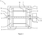
- FIG. 1 represents a partial schematic sectional view of a rotating electrical machine 1 having an axis of rotation A.
- the rotating electrical machine 1 comprises a stator 2 and a rotor 3 in a casing.
- the rotor 3 is capable of interacting with the stator 2.
- the casing comprises for example a first bearing 5, a second bearing 6 and a tubular spacer 7.
- the tubular spacer 7 is for example clamped between the first bearing 5 and the second bearing 6, for example by means of tie rods not shown between the first bearing 5 and the second bearing 6.
- the stator is fixed inside the casing, for example mounted tightly in the tubular spacer 7.
- the terms radial and radially are understood to mean in relation to the axis of rotation A.
- the terms longitudinal and longitudinally mean in the direction of the axis of rotation A.
- the tubular spacer comprises a cooling chamber in which a cooling liquid circulates.
- the stator comprises a stator body 9 and a winding 8.
- the stator body 9 comprises, for example, a first stack of magnetic sheets.
- the winding 8 comprises electrical conductors, an active part of which passes through notches formed in the stator body 9 and a connection part or bun is formed outside the notches.
- the winding 8 is, for example, a hairpin-type winding.
- the rotor 3 is for example fixed on a shaft 4 with an axis of rotation A.
- the shaft 4 is guided in rotation by a first bearing 11 mounted in the first bearing 5 and a second bearing 12 mounted in the second bearing 6.
- a drive element 13, for example a pulley or a gear is fixed to the shaft 4.
- the shaft 4 is guided in rotation relative to the first bearing and the second bearing by means of other known rotational guiding means, for example plain bearings.
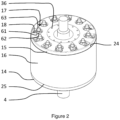
- FIG. 2 represents the rotor 3 according to a first embodiment and the shaft 4.
- the rotor 3 comprises a rotor body 16.
- the rotor body 16 extends longitudinally from a first end 24 of the rotor body 16 to a second end 25 of the rotor body 16.
- the rotor 3 further comprises a first holding assembly 15 bearing on the first end 24 of the rotor body 16.
- the rotor 3 also comprises a second holding assembly 14 bearing on the second end 25 of the rotor body 16. The rotor body 16 is then clamped between the first holding assembly 15 and the second holding assembly 14.
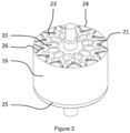
- FIG. 3 is a partial view of rotor 3 and shaft 4.
- the first holding assembly 15 is not shown to allow a more detailed view of the other components of the rotor 3.
- First cavities 23, for example longitudinal, are formed in the rotor body 16.
- the rotor body 16 comprises for example a second stack of magnetic sheets.
- the rotor 3 further comprises permanent magnets 26, for example longitudinal, housed in the first cavities 23.
- the permanent magnets 26 comprise a plurality of elementary permanent magnets.
- the permanent magnets comprise a single elementary permanent magnet.
- a fixing space 29 is formed between at least a first face 28 of at least one of the permanent magnets 26 and a second face 27 of one of the first cavities 23 in which the at least one permanent magnet 26 is housed.
- a resin 64 is inserted into the fixing space. The resin is not shown in the figures 1 to 10 to improve the readability of these figures. The resin 64 participates in the fixing of the permanent magnets 26 in the first cavities 23 of the rotor body 16.
- the rotor 3 comprises magnetic poles formed by two permanent magnets forming a V shape in a plane orthogonal to the axis of rotation.
- the magnetic poles of the rotor are formed by three permanent magnets forming a U shape in a plane orthogonal to the axis of rotation.
- the magnetic poles of the rotor are formed by a U-shaped magnet in a plane orthogonal to the axis of rotation.
- the magnetic poles of the rotor are formed by radially magnetized magnets.
- the fixing space 29 may comprise a first housing 38 and a second housing 39.
- the first holding assembly 15 comprises a supply passage 18 communicating with the fixing space 29.
- the supply passage 18 is adapted to receive a resin supply device.
- the resin supply device comprises for example a hollow needle penetrating into the supply passage 18 during insertion of the resin 64.
- the resin 64 is for example inserted in liquid form and then polymerized using a heating device.
- the first holding assembly may further comprise a vent 32 communicating with the fixing space 29.
- the vent 32 allows the evacuation of a gas, in particular atmospheric air, during the insertion of the resin 64.
- the supply passage 18 and the vent 32 are for example distinct.
- the feed passage 18 may communicate with several attachment spaces 29.
- the feed passage 18 communicates with two attachment spaces 29.
- the vent 32 may comprise a first passage 34 formed in the first holding assembly 15.
- the first passage 34 comprises for example a first groove 37 formed in the first holding assembly 15.
- the first groove 37 is for example machined in the first holding assembly 15.
- the first passage 34 comprises a first end 30 which opens for example into the fixing space 29.
- the rotor body 16 may comprise a second cavity 35, for example a longitudinal cavity located radially inside the first cavities 23.
- the first passage 34 may comprise a second end 31 opening into the second cavity 35.
- the vent 32 may further comprise a first hole 36 passing through the first holding assembly 15.
- the first hole 36 may open into the second cavity 35.
- the vent also comprises a first hole and the second end of the first passage opens directly into the first hole.
- a first space for example annular, is formed between the shaft and the first holding assembly.
- the second end of the first passage opens into the first space.
- the vent 32 can communicate with several fixing spaces 29.
- the vent 32 communicates with two fixing spaces 29.
- the first passage 34 comprises a first portion 51 of circumferential orientation relative to the axis of rotation A and a second portion 52 for connection with the second cavity 35.
- the first portion 51 connects, for example, two fixing spaces 29.
- the first portion 51 and the second portion 52 are connected to each other.
- the fixing space 29 may comprise a first housing 38 and a second housing 39.
- the first housing 38 and second housing 39 are for example formed opposite two first opposite faces 28 of a permanent magnet 26.
- the supply passage 18 may communicate with the first housing 38 and the vent 32 may communicate with the second housing 39.
- FIG. 6 represents the second holding assembly 14 of the rotor 3 according to the first embodiment of the invention.
- the second holding assembly maintenance 14 may comprise a second passage 40 connecting the first housing 38 to the second housing 39.
- the second passage 40 may comprise a second groove 41 formed in the second holding assembly 14.
- the second groove is for example machined in the second holding assembly 14.
- the second passage 40 can also connect several fixing spaces 29.
- the second passage 40 connects two fixing spaces 29.
- the second passage 40 comprises for example a third portion 53 connecting the first housing 38 to the second housing 39 as well as a fourth portion 54 connecting two third portions.
- the rotor body comprises third cavities 21.
- the third cavities 21 extend from the first end 24 of the rotor body 16 to the second end 25 of the rotor body 16 in the direction of the axis of rotation A.
- the third cavities 21 have an axis parallel to the axis of rotation A.
- the third cavities 21 extend for example between a first radius 42 and a second radius 43, the first radius 42 being smaller than the second radius 43.
- the rotor comprises tie rods 17 passing through the third cavities 21 and through second holes 20 of the first holding assembly 15.
- the tie rods 17 make it possible to clamp the rotor body 16 between the first holding assembly 15 and the second holding assembly 14.
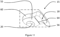
- the first holding assembly may comprise a counterbore 60 having a bottom.
- the bottom may comprise a flat bearing surface 55 on which the tie rod 17 bears.
- the feed passage 18 and the bearing surface 55 may have an edge 56 in common.
- the feed passage 18 and the counterbore 60 may form a funnel or a bowl for the insertion of the resin 64.
- FIG. 11 shows a detail of the first holding assembly and in particular the counterbore 60 as well as the feed passage 18. Resin 64 has been inserted into the feed passage.
- the feed passage 18 can be used as a resin reservoir 64 when inserting the resin 64.
- the feed passage 18 is inscribed between a first plane 57 and a second plane 58 forming an angular sector 59, the first plane 57 and the second plane 58 passing through the axis of rotation A.
- One of the second holes 20 is for example located in the angular sector 59.
- One of the second holes 20 may have an axis 60.
- the axis 60 is located in the angular sector 59.
- Each of the feed passages can be inscribed in an angular sector 59.
- the areas located between the angular sectors 59 of the first holding assembly can for example be machined to balance the rotor 3.
- the tie rods can also pass through third holes 22 of the second holding assembly 14.
- the tie rods comprise, for example, a fixing element 61, in particular a fixing element 61 bearing on the bearing surface 55.
- the tie rod 17 may be a screw and the fixing element is a head of the screw.
- the head of the screw is, for example, supported on the support surface 55.
- the screw may comprise a threaded rod.
- the rod of the screw is, for example, screwed into the second holding assembly, the second holding assembly comprising a third threaded hole or, for example, an overmolded nut for receiving the threaded rod.
- the tie rod 17 comprises a screw 63 and the fixing element is a nut 62.
- the nut 62 bears on the bearing surface 55.
- the nut 62 is for example a flange nut.
- the nut 62 bears on the bearing surface 55 by means of a washer.
- the screw 63 may comprise a head.
- the head bears, for example, on the second holding assembly.
- the head of the screw is overmolded in the second holding assembly.
- the first hole 36 and the feed passage 18 are for example each located radially inside the first radius 42 or outside the second radius 43.
- FIG 8 represents a partial section in secant planes of the rotor 3 according to the first embodiment of the invention. The section is made along a line 33 shown on the Figure 7 .
- This section shows a path 44 followed by the resin 64 and the gas during the insertion of the resin 64 into the fixing space 29.
- FIG 9 represents a partial section in secant planes of the rotor 3 according to the second embodiment of the invention.
- the section is, like that of the figure 8 , made according to a line 33 shown on the Figure 7 .
- the second embodiment of the invention is similar to the first embodiment of the invention. However, the embodiment of the first holding assembly 15 and the second holding assembly 14 is different.
- the first holding assembly 15 may comprise a first end portion 45 and a first intermediate portion 46 of flat shape.
- the first intermediate portion 46 is for example made of sheet metal.
- the first intermediate portion 46 is for example clamped between the first end portion 45 and the rotor body 16.
- the first passage comprises a first opening 47 passing through a thickness of the first intermediate portion 46.
- the first opening 47 is for example made by cutting.
- the second holding assembly 14 may comprise a second end portion 48 and a second intermediate portion 49 of flat shape.
- the second intermediate portion 49 is for example made of sheet metal.
- the second intermediate portion 49 is for example clamped between the second end portion 25 and the rotor body 16.
- the second passage 40 comprises a second opening 50 passing through a thickness of the second intermediate portion 49.
- the second opening 50 is made by cutting.
- first holding assembly is as described for the first embodiment of the invention and the second holding assembly is as described for the second embodiment of the invention.
- the first holding assembly does not include a vent.
- the gas can then be evacuated by the natural rise of the gas to the surface of the resin, in particular in the form of bubbles.
- the second holding assembly does not include a second passage.
- the gas can then be evacuated by natural rise of the gas to the surface of the resin or thanks to a free space provided between the permanent magnet and the second holding assembly.
Landscapes
- Engineering & Computer Science (AREA)
- Power Engineering (AREA)
- Manufacturing & Machinery (AREA)
- Permanent Field Magnets Of Synchronous Machinery (AREA)
- Manufacture Of Motors, Generators (AREA)
Claims (10)
- Rotor (3) für eine umlaufende elektrische Maschine (1), der geeignet ist, mit einem Stator (2) der umlaufenden elektrischen Maschine (1) zu interagieren, und in Bezug auf eine Rotationsachse (A) rotiert, wobei der Rotor (3) umfasst:- einen Rotorkörper (16), umfassend:- erste Hohlräume (23), die sich von einem ersten Ende (24) des Rotorkörpers (16) zu einem zweiten Ende (25) des Rotorkörpers (16) in der Richtung der Rotationsachse (A) erstrecken,- dritte Hohlräume (21), die sich von dem ersten Ende (24) des Rotorkörpers (16) zu dem zweiten Ende (25) des Rotorkörpers (16) in der Richtung der Rotationsachse (A) erstrecken und eine zu der Rotationsachse (A) parallele Achse aufweisen,- Permanentmagnete (26), die in den ersten Hohlräumen (23) aufgenommen sind, wobei ein Fixierungsraum (29) zwischen mindestens einer ersten Seite (28) mindestens eines der Permanentmagnete (26) und einer zweiten Seite (27) eines der ersten Hohlräume (23), in dem der mindestens eine Permanentmagnet (26) aufgenommen ist, gebildet wird,- eine erste Halteanordnung (15), die in Anlage auf dem ersten Ende (24) des Rotorkörpers (16) ist und zweite Löcher (20) umfasst,- eine zweite Halteanordnung (14), die auf dem zweiten Ende (25) des Rotorkörpers (16) aufliegt,- Zugstäbe (17), die in den dritten Hohlräumen (21) und in den zweiten Löchern (20) der ersten Halteanordnung (15) verlaufen und es ermöglichen, den Rotorkörper (16) zwischen der ersten Halteanordnung (15) und der zweiten Halteanordnung (14) einzuspannen,- ein Harz (64), das in den Fixierungsraum (29) eingeführt ist,wobei die erste Halteanordnung (15) einen Versorgungsdurchgang (18) umfasst, der mit dem Fixierungsraum (29) in Verbindung steht, wobei der Versorgungsdurchgang (18) geeignet ist, eine Vorrichtung zur Versorgung mit Harz aufzunehmen,dadurch gekennzeichnet, dass die erste Halteanordnung (15) eine Senkung (60) umfasst, die einen Boden aufweist, wobei der Boden den Versorgungsdurchgang (18) und eine plane Anlagefläche (55) umfasst, auf welcher der Zugstab (17) aufliegt, wobei der Versorgungsdurchgang (18) und die Anlagefläche (55) einen gemeinsamen Rand (56) besitzen, so dass kein Material der ersten Halteanordnung (15) zwischen einem Teil des Zugstabs (17), der auf der ebenen Anlagefläche ruht, und dem Versorgungsdurchgang (18) gelassen wird.
- Rotor (3) nach einem der vorhergehenden Ansprüche, wobei die zweite Halteanordnung (14) dritte Löcher (22) umfasst, in denen die Zugstäbe (17) verlaufen.
- Rotor (3) nach einem der vorhergehenden Ansprüche, wobei, wenn der Versorgungsdurchgang (18) zwischen einer ersten Ebene (57) und einer zweiten Ebene (58), die einen Winkelsektor (59) bilden, einbeschrieben ist, wobei die erste Ebene (57) und die zweite Ebene (58) durch die Rotationsachse (A) verlaufen, eines der zweiten Löcher (20) in dem Winkelsektor (59) gelegen ist.
- Rotor (3) nach einem der Ansprüche 1 bis 2, wobei, wenn der Versorgungsdurchgang (18) zwischen einer ersten Ebene (57) und einer zweiten Ebene (58), die einen Winkelsektor (59) bilden, einbeschrieben ist, wobei die erste Ebene (57) und die zweite Ebene (58) durch die Rotationsachse (A) verlaufen, wobei eines der zweiten Löcher (20) eine Achse (60) aufweist, die Achse (60) in dem Winkelsektor (59) gelegen ist.
- Rotor (3) nach einem der vorhergehenden Ansprüche, wobei der Versorgungsdurchgang (18) mit mehreren Fixierungsräumen (29), insbesondere zwei, in Verbindung steht.
- Rotor (3) nach einem der vorhergehenden Ansprüche, wobei die erste Halteanordnung (15) eine Entlüftungsöffnung (32) umfasst, die mit dem Fixierungsraum (29) in Verbindung steht und geeignet ist, das Abführen eines Gases beim Einführen des Harzes (64) zu ermöglichen, wobei der Versorgungsdurchgang (18) und die Entlüftungsöffnung (32) verschieden sind.
- Rotor (3) nach einem der vorhergehenden Ansprüche, wobei die Zugstäbe ein Fixierungselement (61) umfassen, wobei das Fixierungselement auf der Anlagefläche (55) in Anlage ist.
- Rotor (3) nach dem vorhergehenden Anspruch, wobei der Zugstab (17) eine Schraube ist und das Fixierungselement ein Kopf der Schraube ist, wobei der Kopf der Schraube auf der Anlagefläche (55) in Anlage ist.
- Rotor (3) nach Anspruch 7, wobei der Zugstab (17) eine Schraube (63) umfasst und das Fixierungselement eine Mutter (62) ist, wobei die Mutter (62) auf der Anlagefläche (55) in Anlage ist.
- Umlaufende elektrische Maschine (1), die einen Rotor (3) nach einem der vorhergehenden Ansprüche und einen Stator (2) umfasst.
Applications Claiming Priority (1)
| Application Number | Priority Date | Filing Date | Title |
|---|---|---|---|
| FR2013584A FR3118345B1 (fr) | 2020-12-17 | 2020-12-17 | Rotor de machine électrique tournante et machine électrique tournante équipée d’un tel rotor |
Publications (2)
| Publication Number | Publication Date |
|---|---|
| EP4016818A1 EP4016818A1 (de) | 2022-06-22 |
| EP4016818B1 true EP4016818B1 (de) | 2025-04-02 |
Family
ID=74592244
Family Applications (1)
| Application Number | Title | Priority Date | Filing Date |
|---|---|---|---|
| EP21213284.9A Active EP4016818B1 (de) | 2020-12-17 | 2021-12-09 | Rotor einer umlaufenden elektrischen maschine und mit einem solchen rotor ausgestattete elektrisch umlaufende maschine |
Country Status (2)
| Country | Link |
|---|---|
| EP (1) | EP4016818B1 (de) |
| FR (1) | FR3118345B1 (de) |
Family Cites Families (6)
| Publication number | Priority date | Publication date | Assignee | Title |
|---|---|---|---|---|
| FR2887698B1 (fr) * | 2005-06-28 | 2007-12-07 | Valeo Equip Electr Moteur | Rotor a poles saillants comportant des flasques de maintien comportant des surfaces de contact avec des chignons des bobinages |
| JP2008245405A (ja) * | 2007-03-27 | 2008-10-09 | Aisin Seiki Co Ltd | ロータおよびその製造方法 |
| JP5855515B2 (ja) * | 2012-04-03 | 2016-02-09 | 株式会社三井ハイテック | 回転子積層鉄心の製造方法 |
| JP6144535B2 (ja) | 2013-05-13 | 2017-06-07 | 株式会社三井ハイテック | 回転子鉄心の製造方法及び回転子鉄心 |
| US10284061B2 (en) | 2014-06-09 | 2019-05-07 | Fuji Electric Co., Ltd. | Rotor of permanent magnet-type rotary electric machine |
| FR3069723B1 (fr) * | 2017-07-25 | 2020-10-02 | Valeo Equip Electr Moteur | Rotor de machine electrique tournante muni d'une couche de resine dans les cavites d'aimants permanents |
-
2020
- 2020-12-17 FR FR2013584A patent/FR3118345B1/fr active Active
-
2021
- 2021-12-09 EP EP21213284.9A patent/EP4016818B1/de active Active
Also Published As
| Publication number | Publication date |
|---|---|
| EP4016818A1 (de) | 2022-06-22 |
| FR3118345B1 (fr) | 2024-08-23 |
| FR3118345A1 (fr) | 2022-06-24 |
Similar Documents
| Publication | Publication Date | Title |
|---|---|---|
| EP1362407B1 (de) | Verbesserte rotationsmaschine für automobile fahrzeuge | |
| EP0868770B1 (de) | Basiselement für scheibenformige elektrische Maschine und entsprechende elektrische Maschine | |
| EP3516757B1 (de) | Durch ein zweistromlaufrad gekühlte elektrische maschine | |
| EP3465892B1 (de) | Elektrische drehmaschine mit halteplatte für einen sensor der winkelposition des rotors | |
| EP3931944B1 (de) | Rotierende elektrische maschine mit einer schaltung zur kühlung der magnete über die welle | |
| EP4158754A1 (de) | Rotor für einen elektromotor mit kühlkreislauf | |
| EP4016819A1 (de) | Rotor einer umlaufenden elektrischen maschine und mit einem solchen rotor ausgestattete elektrisch umlaufende maschine | |
| EP4241370A1 (de) | Rotor für eine elektrische drehmaschine | |
| EP4016818A1 (de) | Rotor einer umlaufenden elektrischen maschine und mit einem solchen rotor ausgestattete elektrisch umlaufende maschine | |
| EP3382856A1 (de) | Elektrisch umlaufende maschine mit optimierter kühlung | |
| EP4016816A1 (de) | Baugruppe mit einer elektrischen maschine, einem wechselrichter und einem verbindungsteil | |
| EP4122082B1 (de) | Baugruppe bestehend aus einer rotierenden elektrischen maschine, einem elektronikmodul und einem verbinder | |
| EP3850727B1 (de) | Rotierende elektrische maschine mit einem aus zwei übergossenen teilen hergestellten lager | |
| WO2026017765A1 (fr) | Rotor pour moteur électrique équipé de flasques d'extrémité intégrant des plasto-aimants | |
| FR3086128A1 (fr) | Machine electrique tournante munie d'au moins une gorge de reserve de lubrifiant | |
| FR2864367A1 (fr) | Dispositif de ventilation pour machine electrique tournante autour d'un arbre, a ventilateur independant de l'arbre | |
| WO2023156735A1 (fr) | Rotor pour moteur electrique muni d'un circuit de refroidissement | |
| FR3154880A1 (fr) | Rotor à griffe pour machine électrique tournante à flux axial et machine électrique tournante associée | |
| FR3117697A1 (fr) | Machine électrique tournante pour contrôle pleine onde et à modulation de largeur d’impulsion et ensemble électrique | |
| WO2025257085A1 (fr) | Ensemble de rotor pour une machine électrique à flux axial, notamment de véhicule automobile, et machine électrique à flux axial le comprenant | |
| FR3141014A1 (fr) | Flasque pour une machine électrique tournante | |
| FR3133280A1 (fr) | Moteur électromagnétique à concentration de flux magnétique | |
| FR3124036A1 (fr) | Machine électrique tournante à flux axial multiple ayant une configuration creuse | |
| FR3098057A1 (fr) | Machine electrique tournante munie d'un element de conduction thermique | |
| FR3098040A1 (fr) | Machine electrique tournante à refroidissement par eau |
Legal Events
| Date | Code | Title | Description |
|---|---|---|---|
| PUAI | Public reference made under article 153(3) epc to a published international application that has entered the european phase |
Free format text: ORIGINAL CODE: 0009012 |
|
| STAA | Information on the status of an ep patent application or granted ep patent |
Free format text: STATUS: THE APPLICATION HAS BEEN PUBLISHED |
|
| AK | Designated contracting states |
Kind code of ref document: A1 Designated state(s): AL AT BE BG CH CY CZ DE DK EE ES FI FR GB GR HR HU IE IS IT LI LT LU LV MC MK MT NL NO PL PT RO RS SE SI SK SM TR |
|
| STAA | Information on the status of an ep patent application or granted ep patent |
Free format text: STATUS: REQUEST FOR EXAMINATION WAS MADE |
|
| 17P | Request for examination filed |
Effective date: 20221222 |
|
| P01 | Opt-out of the competence of the unified patent court (upc) registered |
Effective date: 20230528 |
|
| STAA | Information on the status of an ep patent application or granted ep patent |
Free format text: STATUS: EXAMINATION IS IN PROGRESS |
|
| 17Q | First examination report despatched |
Effective date: 20240611 |
|
| RAP1 | Party data changed (applicant data changed or rights of an application transferred) |
Owner name: VALEO ELECTRIFICATION |
|
| GRAP | Despatch of communication of intention to grant a patent |
Free format text: ORIGINAL CODE: EPIDOSNIGR1 |
|
| STAA | Information on the status of an ep patent application or granted ep patent |
Free format text: STATUS: GRANT OF PATENT IS INTENDED |
|
| INTG | Intention to grant announced |
Effective date: 20241106 |
|
| GRAS | Grant fee paid |
Free format text: ORIGINAL CODE: EPIDOSNIGR3 |
|
| GRAA | (expected) grant |
Free format text: ORIGINAL CODE: 0009210 |
|
| STAA | Information on the status of an ep patent application or granted ep patent |
Free format text: STATUS: THE PATENT HAS BEEN GRANTED |
|
| AK | Designated contracting states |
Kind code of ref document: B1 Designated state(s): AL AT BE BG CH CY CZ DE DK EE ES FI FR GB GR HR HU IE IS IT LI LT LU LV MC MK MT NL NO PL PT RO RS SE SI SK SM TR |
|
| REG | Reference to a national code |
Ref country code: GB Ref legal event code: FG4D Free format text: NOT ENGLISH |
|
| REG | Reference to a national code |
Ref country code: CH Ref legal event code: EP |
|
| REG | Reference to a national code |
Ref country code: IE Ref legal event code: FG4D Free format text: LANGUAGE OF EP DOCUMENT: FRENCH |
|
| REG | Reference to a national code |
Ref country code: DE Ref legal event code: R096 Ref document number: 602021028466 Country of ref document: DE |
|
| REG | Reference to a national code |
Ref country code: NL Ref legal event code: MP Effective date: 20250402 |
|
| PG25 | Lapsed in a contracting state [announced via postgrant information from national office to epo] |
Ref country code: NL Free format text: LAPSE BECAUSE OF FAILURE TO SUBMIT A TRANSLATION OF THE DESCRIPTION OR TO PAY THE FEE WITHIN THE PRESCRIBED TIME-LIMIT Effective date: 20250402 |
|
| REG | Reference to a national code |
Ref country code: AT Ref legal event code: MK05 Ref document number: 1782295 Country of ref document: AT Kind code of ref document: T Effective date: 20250402 |
|
| PG25 | Lapsed in a contracting state [announced via postgrant information from national office to epo] |
Ref country code: FI Free format text: LAPSE BECAUSE OF FAILURE TO SUBMIT A TRANSLATION OF THE DESCRIPTION OR TO PAY THE FEE WITHIN THE PRESCRIBED TIME-LIMIT Effective date: 20250402 Ref country code: PT Free format text: LAPSE BECAUSE OF FAILURE TO SUBMIT A TRANSLATION OF THE DESCRIPTION OR TO PAY THE FEE WITHIN THE PRESCRIBED TIME-LIMIT Effective date: 20250804 Ref country code: ES Free format text: LAPSE BECAUSE OF FAILURE TO SUBMIT A TRANSLATION OF THE DESCRIPTION OR TO PAY THE FEE WITHIN THE PRESCRIBED TIME-LIMIT Effective date: 20250402 |
|
| REG | Reference to a national code |
Ref country code: LT Ref legal event code: MG9D |
|
| PG25 | Lapsed in a contracting state [announced via postgrant information from national office to epo] |
Ref country code: NO Free format text: LAPSE BECAUSE OF FAILURE TO SUBMIT A TRANSLATION OF THE DESCRIPTION OR TO PAY THE FEE WITHIN THE PRESCRIBED TIME-LIMIT Effective date: 20250702 Ref country code: GR Free format text: LAPSE BECAUSE OF FAILURE TO SUBMIT A TRANSLATION OF THE DESCRIPTION OR TO PAY THE FEE WITHIN THE PRESCRIBED TIME-LIMIT Effective date: 20250703 |
|
| PG25 | Lapsed in a contracting state [announced via postgrant information from national office to epo] |
Ref country code: PL Free format text: LAPSE BECAUSE OF FAILURE TO SUBMIT A TRANSLATION OF THE DESCRIPTION OR TO PAY THE FEE WITHIN THE PRESCRIBED TIME-LIMIT Effective date: 20250402 |
|
| PG25 | Lapsed in a contracting state [announced via postgrant information from national office to epo] |
Ref country code: BG Free format text: LAPSE BECAUSE OF FAILURE TO SUBMIT A TRANSLATION OF THE DESCRIPTION OR TO PAY THE FEE WITHIN THE PRESCRIBED TIME-LIMIT Effective date: 20250402 |
|
| PG25 | Lapsed in a contracting state [announced via postgrant information from national office to epo] |
Ref country code: HR Free format text: LAPSE BECAUSE OF FAILURE TO SUBMIT A TRANSLATION OF THE DESCRIPTION OR TO PAY THE FEE WITHIN THE PRESCRIBED TIME-LIMIT Effective date: 20250402 |
|
| PG25 | Lapsed in a contracting state [announced via postgrant information from national office to epo] |
Ref country code: AT Free format text: LAPSE BECAUSE OF FAILURE TO SUBMIT A TRANSLATION OF THE DESCRIPTION OR TO PAY THE FEE WITHIN THE PRESCRIBED TIME-LIMIT Effective date: 20250402 |
|
| PG25 | Lapsed in a contracting state [announced via postgrant information from national office to epo] |
Ref country code: RS Free format text: LAPSE BECAUSE OF FAILURE TO SUBMIT A TRANSLATION OF THE DESCRIPTION OR TO PAY THE FEE WITHIN THE PRESCRIBED TIME-LIMIT Effective date: 20250702 |
|
| PG25 | Lapsed in a contracting state [announced via postgrant information from national office to epo] |
Ref country code: IS Free format text: LAPSE BECAUSE OF FAILURE TO SUBMIT A TRANSLATION OF THE DESCRIPTION OR TO PAY THE FEE WITHIN THE PRESCRIBED TIME-LIMIT Effective date: 20250802 |
|
| PG25 | Lapsed in a contracting state [announced via postgrant information from national office to epo] |
Ref country code: LV Free format text: LAPSE BECAUSE OF FAILURE TO SUBMIT A TRANSLATION OF THE DESCRIPTION OR TO PAY THE FEE WITHIN THE PRESCRIBED TIME-LIMIT Effective date: 20250402 |
|
| REG | Reference to a national code |
Ref country code: DE Ref legal event code: R097 Ref document number: 602021028466 Country of ref document: DE |
|
| PG25 | Lapsed in a contracting state [announced via postgrant information from national office to epo] |
Ref country code: DK Free format text: LAPSE BECAUSE OF FAILURE TO SUBMIT A TRANSLATION OF THE DESCRIPTION OR TO PAY THE FEE WITHIN THE PRESCRIBED TIME-LIMIT Effective date: 20250402 Ref country code: SM Free format text: LAPSE BECAUSE OF FAILURE TO SUBMIT A TRANSLATION OF THE DESCRIPTION OR TO PAY THE FEE WITHIN THE PRESCRIBED TIME-LIMIT Effective date: 20250402 |
|
| PGFP | Annual fee paid to national office [announced via postgrant information from national office to epo] |
Ref country code: FR Payment date: 20251230 Year of fee payment: 5 |
|
| PG25 | Lapsed in a contracting state [announced via postgrant information from national office to epo] |
Ref country code: CZ Free format text: LAPSE BECAUSE OF FAILURE TO SUBMIT A TRANSLATION OF THE DESCRIPTION OR TO PAY THE FEE WITHIN THE PRESCRIBED TIME-LIMIT Effective date: 20250402 |
|
| PG25 | Lapsed in a contracting state [announced via postgrant information from national office to epo] |
Ref country code: EE Free format text: LAPSE BECAUSE OF FAILURE TO SUBMIT A TRANSLATION OF THE DESCRIPTION OR TO PAY THE FEE WITHIN THE PRESCRIBED TIME-LIMIT Effective date: 20250402 |
|
| PG25 | Lapsed in a contracting state [announced via postgrant information from national office to epo] |
Ref country code: RO Free format text: LAPSE BECAUSE OF FAILURE TO SUBMIT A TRANSLATION OF THE DESCRIPTION OR TO PAY THE FEE WITHIN THE PRESCRIBED TIME-LIMIT Effective date: 20250402 Ref country code: SK Free format text: LAPSE BECAUSE OF FAILURE TO SUBMIT A TRANSLATION OF THE DESCRIPTION OR TO PAY THE FEE WITHIN THE PRESCRIBED TIME-LIMIT Effective date: 20250402 |
|
| PG25 | Lapsed in a contracting state [announced via postgrant information from national office to epo] |
Ref country code: IT Free format text: LAPSE BECAUSE OF FAILURE TO SUBMIT A TRANSLATION OF THE DESCRIPTION OR TO PAY THE FEE WITHIN THE PRESCRIBED TIME-LIMIT Effective date: 20250402 |
|
| PLBE | No opposition filed within time limit |
Free format text: ORIGINAL CODE: 0009261 |
|
| STAA | Information on the status of an ep patent application or granted ep patent |
Free format text: STATUS: NO OPPOSITION FILED WITHIN TIME LIMIT |
|
| REG | Reference to a national code |
Ref country code: CH Ref legal event code: L10 Free format text: ST27 STATUS EVENT CODE: U-0-0-L10-L00 (AS PROVIDED BY THE NATIONAL OFFICE) Effective date: 20260211 |
|
| 26N | No opposition filed |
Effective date: 20260105 |
|
| PGFP | Annual fee paid to national office [announced via postgrant information from national office to epo] |
Ref country code: DE Payment date: 20251231 Year of fee payment: 5 |