EP4016723A1 - Electrolyte injection device and electrolyte injection method using same - Google Patents
Electrolyte injection device and electrolyte injection method using same Download PDFInfo
- Publication number
- EP4016723A1 EP4016723A1 EP20893516.3A EP20893516A EP4016723A1 EP 4016723 A1 EP4016723 A1 EP 4016723A1 EP 20893516 A EP20893516 A EP 20893516A EP 4016723 A1 EP4016723 A1 EP 4016723A1
- Authority
- EP
- European Patent Office
- Prior art keywords
- battery cell
- electrolyte
- movable pressing
- electrolyte injection
- preliminary battery
- Prior art date
- Legal status (The legal status is an assumption and is not a legal conclusion. Google has not performed a legal analysis and makes no representation as to the accuracy of the status listed.)
- Granted
Links
Images



Classifications
-
- H—ELECTRICITY
- H01—ELECTRIC ELEMENTS
- H01M—PROCESSES OR MEANS, e.g. BATTERIES, FOR THE DIRECT CONVERSION OF CHEMICAL ENERGY INTO ELECTRICAL ENERGY
- H01M50/00—Constructional details or processes of manufacture of the non-active parts of electrochemical cells other than fuel cells, e.g. hybrid cells
- H01M50/60—Arrangements or processes for filling or topping-up with liquids; Arrangements or processes for draining liquids from casings
-
- H—ELECTRICITY
- H01—ELECTRIC ELEMENTS
- H01M—PROCESSES OR MEANS, e.g. BATTERIES, FOR THE DIRECT CONVERSION OF CHEMICAL ENERGY INTO ELECTRICAL ENERGY
- H01M50/00—Constructional details or processes of manufacture of the non-active parts of electrochemical cells other than fuel cells, e.g. hybrid cells
- H01M50/60—Arrangements or processes for filling or topping-up with liquids; Arrangements or processes for draining liquids from casings
- H01M50/609—Arrangements or processes for filling with liquid, e.g. electrolytes
-
- H—ELECTRICITY
- H01—ELECTRIC ELEMENTS
- H01M—PROCESSES OR MEANS, e.g. BATTERIES, FOR THE DIRECT CONVERSION OF CHEMICAL ENERGY INTO ELECTRICAL ENERGY
- H01M50/00—Constructional details or processes of manufacture of the non-active parts of electrochemical cells other than fuel cells, e.g. hybrid cells
- H01M50/10—Primary casings; Jackets or wrappings
-
- H—ELECTRICITY
- H01—ELECTRIC ELEMENTS
- H01M—PROCESSES OR MEANS, e.g. BATTERIES, FOR THE DIRECT CONVERSION OF CHEMICAL ENERGY INTO ELECTRICAL ENERGY
- H01M50/00—Constructional details or processes of manufacture of the non-active parts of electrochemical cells other than fuel cells, e.g. hybrid cells
- H01M50/10—Primary casings; Jackets or wrappings
- H01M50/102—Primary casings; Jackets or wrappings characterised by their shape or physical structure
- H01M50/105—Pouches or flexible bags
-
- Y—GENERAL TAGGING OF NEW TECHNOLOGICAL DEVELOPMENTS; GENERAL TAGGING OF CROSS-SECTIONAL TECHNOLOGIES SPANNING OVER SEVERAL SECTIONS OF THE IPC; TECHNICAL SUBJECTS COVERED BY FORMER USPC CROSS-REFERENCE ART COLLECTIONS [XRACs] AND DIGESTS
- Y02—TECHNOLOGIES OR APPLICATIONS FOR MITIGATION OR ADAPTATION AGAINST CLIMATE CHANGE
- Y02E—REDUCTION OF GREENHOUSE GAS [GHG] EMISSIONS, RELATED TO ENERGY GENERATION, TRANSMISSION OR DISTRIBUTION
- Y02E60/00—Enabling technologies; Technologies with a potential or indirect contribution to GHG emissions mitigation
- Y02E60/10—Energy storage using batteries
Definitions
- the present invention relates to an electrolyte injection device and an electrolyte injection method using the same, and more particularly to an electrolyte injection device including a structure capable of pressing and fixing a preliminary battery cell in order to prevent folding of a separator of an electrode assembly in the process of injecting an electrolyte for manufacturing a battery cell and an electrolyte injection method using the same.
- a lithium secondary battery which is reusable and has high energy density, has attracted attention as a new energy source having environmentally friendly characteristics, since the lithium secondary battery is capable of remarkably reducing the use of fossil fuels and generates no byproducts as the result of using energy.
- the lithium secondary battery may be classified as a pouch-shaped battery cell made of a laminate sheet, a cylindrical battery cell made of a metal can, or a prismatic battery cell based on the kind and shape of a sheathing material.
- An electrode assembly is classified as a jelly-roll type electrode assembly, a stacked type electrode assembly, or a stacked/folded type or laminated/stacked type electrode assembly based on the shape thereof.
- the pouch-shaped lithium secondary battery is manufactured by receiving an electrode assembly and an electrolyte in a pouch-shaped battery case made of a laminate sheet, and then sealing an outer periphery of the battery case by a heating and pressing method.
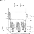
- FIG. 1 shows a part of a process of injecting an electrolyte into a conventional pouch-shaped battery cell
- FIG. 2 is a plan view showing a state in which an electrolyte injection pipe is omitted in FIG. 1 .
- an electrolyte injection device includes a base portion 110, a jig 120, and an electrolyte injection pipe 130, and the jig 120 has a structure in which the jig 120 is fixed to the base portion 110 and is in a state that cannot be moved.
- Two pairs of jigs 120 facing each other based on a space in which a preliminary battery cell 101 is accommodated are fixedly disposed on the base portion 110, and an x-direction distance d2 between the jigs 120 is greater than a thickness d1 of the preliminary battery cell 110. Therefore, it is possible to easily insert and remove the preliminary battery cell 110 between the jigs.
- the jig is not in close contact with the preliminary battery cell but is located with spacing apart therefrom, and thus the jig is used as a cradle for the preliminary battery cell.
- the present invention has been made in view of the above problems, and it is an object of the present invention to provide an electrolyte injection device including a movable pressing jig including a portion for fixing and pressing a battery cell, and an electrolyte injection method using the same, in order to prevent an interface between an electrode and a separator from being peeled off or a separator from being folded during the electrolyte injection process.
- an electrolyte injection device includes a base portion on which a preliminary battery cell is disposed on an upper surface thereof, a movable pressing jig attached to the base portion, and an electrolyte injection pipe configured to inject an electrolyte into the preliminary battery cell, wherein the movable pressing jig includes a portion configured to press the preliminary battery cell in a direction perpendicular to an upper surface and a lower surface of an electrode assembly receiving portion of the preliminary battery cell.
- the movable pressing jig may be configured to have a structure in which an outer periphery of an electrode assembly in a direction in which the electrolyte is injected is pressed.
- the movable pressing jig may include a pressing portion configured to press the preliminary battery cell, and a support portion configured to support the pressing portion.
- the pressing portion in a state in which the movable pressing jig presses the preliminary battery cell, the pressing portion may be in close contact with the preliminary battery cell to press the preliminary battery cell, and the support portion may be spaced apart from the preliminary battery cell.
- the movable pressing jig may be constituted by a plurality of unit movable pressing jigs, and the plurality of unit movable pressing jigs may be disposed to be spaced apart from neighboring unit movable pressing jigs such that the electrolyte moves into the preliminary battery cell.
- the pressing portion may be configured such that a surface facing the preliminary battery cell is a plane parallel to an outer surface of the preliminary battery cell.
- the pressing portion may be configured such that a surface facing the preliminary battery cell is a plane inclined with respect to an outer surface of the preliminary battery cell.
- the electrolyte injection pipe may spray the electrolyte toward a portion of an outer periphery of the electrode assembly in which the movable pressing jig is not disposed.
- the present invention provides a method of manufacturing a battery cell using the electrolyte injection device, in particular, the method including: moving a movable pressing jig in a first direction so as to increase a distance between the movable pressing jigs in order to secure a position on which a preliminary battery cell is disposed; positioning the preliminary battery cell on a base portion; pressing the preliminary battery cell by moving the movable pressing jig in a second direction so as to narrow the distance between the movable pressing jigs; and injecting an electrolyte into the preliminary battery cell.
- the movable pressing jig may include three or more pairs of unit movable pressing jigs facing each other with the preliminary battery cell interposed therebetween.
- the preliminary battery cell may be separated from the base portion by moving the movable pressing jig again in the first direction after the step of injecting the electrolyte.
- the electrolyte injection pipe may spray the electrolyte toward a portion in which the movable pressing jig does not press a battery cell.
- the present invention also provides a pouch-shaped battery cell manufactured by using the electrolyte injection method, and includes a battery pack including the battery cell as a unit battery cell.
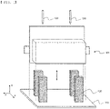
- FIG. 3 is a front view showing a portion of a process of injecting an electrolyte into a preliminary battery cell using an electrolyte injection device according to the present invention.
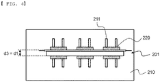
- FIG. 4 is a plan view showing a state in which an electrolyte injection pipe is omitted in FIG. 3 .
- an electrolyte injection device includes a base portion 210 on which a preliminary battery cell 201 is disposed on an upper surface thereof, a movable pressing jig 220 attached to the base portion, and an electrolyte injection pipe 230 configured to inject an electrolyte into the preliminary battery cell, wherein a groove 211 is formed on the upper surface of the base portion 210 so as to move the movable pressing jig 220 in an x-axis direction.
- the preliminary battery cell refers to a battery cell in a stage prior to an assembled battery cell.
- a battery cell in which an electrolyte is injected while being fixed to an electrolyte injection device is referred to as a preliminary battery cell.
- the preliminary battery cell is a type in which an electrolyte is injected before a battery case is completely sealed.
- it may be a pouch-shaped battery cell.
- Each of the two movable pressing jigs 220 disposed on both sides facing each other based on the preliminary battery cell 201 is arranged in pairs.
- the movable pressing jigs may move in a first direction, which is a direction in which the distance between each other is increased, or may move in a second direction, which is a direction in which the distance between each other becomes close.
- the movable pressing jig includes a portion configured to press the preliminary battery cell in a direction perpendicular to an upper surface 204 of an electrode assembly receiving portion 203 of the preliminary battery cell and a lower surface 205 of the electrode assembly receiving portion of the preliminary battery cell, whereby only a portion of the movable pressing jig presses the preliminary battery cell.
- the movable pressing jig 220 includes a pressing portion 221 configured to press the preliminary battery cell 201 and a support portion 222 configured to move the movable pressing jig through a groove 211 while supporting the pressing portion 221.
- the pressing portion 221 presses the preliminary battery cell in close contact with an outer surface of the preliminary battery cell 201 to prevent the separator from being separated from an electrode or folded, and the support portion does not contact the preliminary battery cell.
- the movable pressing jig presses the entire upper and lower surfaces of the electrode assembly receiving portion, it is difficult for the electrolyte to penetrate into the electrode assembly, and the amount of the injected electrolyte may be lowered, which is not preferable.
- the movable pressing jig according to the present invention is configured to have a structure in which the movable pressing jig presses the outer periphery of the electrode assembly in a direction in which the electrolyte is injected and does not press the rest of the electrode assembly, whereby it is possible to prevent the separator from being folded by the injection of the electrolyte while it is possible to prevent the electrolyte impregnation property of the electrode assembly from deteriorating.
- the movable pressing jig is constituted by a plurality of unit movable pressing jigs, and the plurality of unit movable pressing jigs may be disposed to be spaced apart from neighboring unit movable pressing jigs such that the electrolyte can move into the preliminary battery cell.
- FIG. 3 shows a state in which three pairs of unit movable pressing jigs 220A are spaced apart from each other.
- the number of pairs of the unit movable pressing jigs may also be applied in three or more pairs in consideration of a total length of the battery cell.
- FIG. 4 shows a state in which a thickness d1 of the preliminary battery cell and a distance d3 between the pressing portions in the state in which the movable pressing jig presses are the same.
- the distance d3 between the pressing portions in the state in which the movable pressing jig presses may be shorter than the thickness d1 of the preliminary battery cell in an x-direction.
- a thickness of a portion pressed by the pressing portion may be relatively thinner than a thickness of a portion not pressed by the pressing portion.
- the electrolyte injection pipe 230 sprays the electrolyte toward a portion of the outer periphery of the electrode assembly in which the movable pressing jig 220 is not disposed.
- FIG. 5 is a perspective view of movable pressing jigs
- FIG. 6 is a side view showing a state in which the movable pressing jigs of FIG. 5 are in close contact with an outer surface of a preliminary battery cell.
- each of a support portion 222 and a support portion 322 is coupled to a position retracted from the preliminary battery cell than each of a pressing portion 221 and a pressing portion 321 in close contact with the preliminary battery cell.
- the pressing portion presses the preliminary battery cell in close contact with the preliminary battery cell, while the support portion is spaced apart from the preliminary battery cell. Therefore, only a portion of an electrode assembly of the preliminary battery cell in close contact with the pressing portion is pressed.
- the pressing portion 221 has a surface 224 facing the preliminary battery cell, which is a plane parallel to an outer surface of the preliminary battery cell.
- the pressing portion 321 has a surface 324 facing the preliminary battery cell, which is a plane inclined with respect to the outer surface of the preliminary battery cell.
- the separator extending from the outer periphery of the electrode assembly can be more stably fixed, while the pressing force on the outer surface of the electrode assembly is weakly applied, whereby it is possible to improve the electrolyte impregnation property.
- a specific electrolyte injection method includes moving a movable pressing jig in a first direction so as to increase a distance between the movable pressing jigs in order to secure a position on which a preliminary battery cell is disposed; positioning the preliminary battery cell on a base portion; pressing the preliminary battery cell by moving the movable pressing jig in a second direction so as to narrow the distance between the movable pressing jigs; and injecting an electrolyte into the preliminary battery cell.
- the electrolyte is sprayed toward a portion in which the movable pressing jig does not press a battery cell, thereby preventing the electrolyte from being bounced out of the preliminary battery cell by the movable pressing jig.
- the movable pressing jig moves in the first direction again to separate the preliminary battery cell from the base portion.
- the separated preliminary battery cell is subjected to a temporarily sealing of an outer periphery of the separated preliminary battery cell in a direction in which the electrolyte is injected and an activation process. Thereafter, the separated preliminary battery cell may be subjected to an exhaust process and a resealing process to manufacture a pouch-shaped battery cell.
- the bonding state of the electrode and the separator is stably fixed since the pressing portion strongly presses the electrode assembly of the preliminary battery cell.
- an electrolyte is injected while pressing a case of a preliminary battery cell surrounding an electrode assembly, whereby it is possible to prevent a separator from falling off an electrode even if the injection pressure of the electrolyte is high.
- the electrolyte is injected in a state in which the adhesion between the electrode and the separator is stably maintained, it is possible to prevent a phenomenon in which the separator is rolled into the electrode.
- the movable pressing jig is of a movable form, it is possible to easily detach the preliminary battery cell from the electrolyte injection device by increasing a distance between the movable pressing jigs or moving the movable pressing jigs closer.
Landscapes
- Chemical & Material Sciences (AREA)
- Chemical Kinetics & Catalysis (AREA)
- Electrochemistry (AREA)
- General Chemical & Material Sciences (AREA)
- Filling, Topping-Up Batteries (AREA)
- Secondary Cells (AREA)
Abstract
Description
- This application claims the benefit of priority to
Korean Patent Application No. 2019-0152102 filed on November 25, 2019 - The present invention relates to an electrolyte injection device and an electrolyte injection method using the same, and more particularly to an electrolyte injection device including a structure capable of pressing and fixing a preliminary battery cell in order to prevent folding of a separator of an electrode assembly in the process of injecting an electrolyte for manufacturing a battery cell and an electrolyte injection method using the same.
- A lithium secondary battery, which is reusable and has high energy density, has attracted attention as a new energy source having environmentally friendly characteristics, since the lithium secondary battery is capable of remarkably reducing the use of fossil fuels and generates no byproducts as the result of using energy.
- The lithium secondary battery may be classified as a pouch-shaped battery cell made of a laminate sheet, a cylindrical battery cell made of a metal can, or a prismatic battery cell based on the kind and shape of a sheathing material. An electrode assembly is classified as a jelly-roll type electrode assembly, a stacked type electrode assembly, or a stacked/folded type or laminated/stacked type electrode assembly based on the shape thereof.
- The pouch-shaped lithium secondary battery is manufactured by receiving an electrode assembly and an electrolyte in a pouch-shaped battery case made of a laminate sheet, and then sealing an outer periphery of the battery case by a heating and pressing method.
- In connection therewith,
FIG. 1 shows a part of a process of injecting an electrolyte into a conventional pouch-shaped battery cell, andFIG. 2 is a plan view showing a state in which an electrolyte injection pipe is omitted inFIG. 1 . - Referring to
FIGS. 1 and2 , an electrolyte injection device includes abase portion 110, ajig 120, and anelectrolyte injection pipe 130, and thejig 120 has a structure in which thejig 120 is fixed to thebase portion 110 and is in a state that cannot be moved. - Two pairs of
jigs 120 facing each other based on a space in which apreliminary battery cell 101 is accommodated are fixedly disposed on thebase portion 110, and an x-direction distance d2 between thejigs 120 is greater than a thickness d1 of thepreliminary battery cell 110. Therefore, it is possible to easily insert and remove thepreliminary battery cell 110 between the jigs. - As described above, the jig is not in close contact with the preliminary battery cell but is located with spacing apart therefrom, and thus the jig is used as a cradle for the preliminary battery cell.
- In general, important considerations in the electrolyte injection process are the amount of electrolyte and the injection rate of the electrolyte. In order to increase the production rate, as the injection rate of the electrolyte is increased, the force exerted by the electrolyte to an electrode assembly is also increasing. Thus, a phenomenon in which an interface between an electrode and a separator is peeled off or a separator is folded into an electrode is increasing.
- Moreover, as shown in
FIGS. 1 and2 , when the jig of the electrolyte injection device is disposed to be spaced apart from a pouch-shaped battery cell, the possibility of occurrence of the above problems is further increased. - Therefore, there is a high necessity for a technology to prevent a phenomenon in which a separator is folded or an interface between an electrode and a separator is peeled off in the process of injecting an electrolyte into a pouch-shaped battery cell.
- The present invention has been made in view of the above problems, and it is an object of the present invention to provide an electrolyte injection device including a movable pressing jig including a portion for fixing and pressing a battery cell, and an electrolyte injection method using the same, in order to prevent an interface between an electrode and a separator from being peeled off or a separator from being folded during the electrolyte injection process.
- In order to accomplish the above object, an electrolyte injection device according to the present invention includes a base portion on which a preliminary battery cell is disposed on an upper surface thereof, a movable pressing jig attached to the base portion, and an electrolyte injection pipe configured to inject an electrolyte into the preliminary battery cell, wherein the movable pressing jig includes a portion configured to press the preliminary battery cell in a direction perpendicular to an upper surface and a lower surface of an electrode assembly receiving portion of the preliminary battery cell.
- The movable pressing jig may be configured to have a structure in which an outer periphery of an electrode assembly in a direction in which the electrolyte is injected is pressed.
- The movable pressing jig may include a pressing portion configured to press the preliminary battery cell, and a support portion configured to support the pressing portion.
- In a concrete example, in a state in which the movable pressing jig presses the preliminary battery cell, the pressing portion may be in close contact with the preliminary battery cell to press the preliminary battery cell, and the support portion may be spaced apart from the preliminary battery cell.
- The movable pressing jig may be constituted by a plurality of unit movable pressing jigs, and the plurality of unit movable pressing jigs may be disposed to be spaced apart from neighboring unit movable pressing jigs such that the electrolyte moves into the preliminary battery cell.
- The pressing portion may be configured such that a surface facing the preliminary battery cell is a plane parallel to an outer surface of the preliminary battery cell.
- Alternatively, the pressing portion may be configured such that a surface facing the preliminary battery cell is a plane inclined with respect to an outer surface of the preliminary battery cell.
- The electrolyte injection pipe may spray the electrolyte toward a portion of an outer periphery of the electrode assembly in which the movable pressing jig is not disposed.
- The present invention provides a method of manufacturing a battery cell using the electrolyte injection device, in particular, the method including: moving a movable pressing jig in a first direction so as to increase a distance between the movable pressing jigs in order to secure a position on which a preliminary battery cell is disposed; positioning the preliminary battery cell on a base portion; pressing the preliminary battery cell by moving the movable pressing jig in a second direction so as to narrow the distance between the movable pressing jigs; and injecting an electrolyte into the preliminary battery cell.
- The movable pressing jig may include three or more pairs of unit movable pressing jigs facing each other with the preliminary battery cell interposed therebetween.
- Further, the preliminary battery cell may be separated from the base portion by moving the movable pressing jig again in the first direction after the step of injecting the electrolyte.
- In the step of injecting the electrolyte, the electrolyte injection pipe may spray the electrolyte toward a portion in which the movable pressing jig does not press a battery cell.
- The present invention also provides a pouch-shaped battery cell manufactured by using the electrolyte injection method, and includes a battery pack including the battery cell as a unit battery cell.
-
-
FIG. 1 is a perspective view showing a part of a process of injecting an electrolyte into a conventional pouch-shaped battery cell. -
FIG. 2 is a plan view showing a state in which an electrolyte injection pipe is omitted inFIG. 1 . -
FIG. 3 is a front view showing a portion of a process of injecting an electrolyte into a preliminary battery cell using an electrolyte injection device according to the present invention. -
FIG. 4 is a plan view showing a state in which an electrolyte injection pipe is omitted inFIG. 3 . -
FIG. 5 is a perspective view of movable pressing jigs. -
FIG. 6 is a side view showing a state in which the movable pressing jigs ofFIG. 5 are in close contact with an outer surface of a preliminary battery cell. - Now, preferred embodiments of the present invention will be described in detail with reference to the accompanying drawings such that the preferred embodiments of the present invention can be easily implemented by a person having ordinary skill in the art to which the present invention pertains. In describing the principle of operation of the preferred embodiments of the present invention in detail, however, a detailed description of known functions and configurations incorporated herein will be omitted when the same may obscure the subject matter of the present invention.
- In addition, the same reference numbers will be used throughout the drawings to refer to parts that perform similar functions or operations. In the case in which one part is said to be connected to another part in the entire specification, not only may the one part be directly connected to the other part, but also, the one part may be indirectly connected to the other part via a further part. In addition, that a certain element is included does not mean that other elements are excluded, but means that such elements may be further included unless mentioned otherwise.
- A description to embody elements through limitation or addition in this specification may be applied to all inventions, unless particularly restricted, and does not limit a specific invention.
- Hereinafter, an embodiment of the present invention will be described in detail with reference to the accompanying drawings.
-
FIG. 3 is a front view showing a portion of a process of injecting an electrolyte into a preliminary battery cell using an electrolyte injection device according to the present invention. -
FIG. 4 is a plan view showing a state in which an electrolyte injection pipe is omitted inFIG. 3 . - Referring to
FIGS. 3 and4 , an electrolyte injection device includes abase portion 210 on which apreliminary battery cell 201 is disposed on an upper surface thereof, a movablepressing jig 220 attached to the base portion, and anelectrolyte injection pipe 230 configured to inject an electrolyte into the preliminary battery cell, wherein agroove 211 is formed on the upper surface of thebase portion 210 so as to move the movablepressing jig 220 in an x-axis direction. - The preliminary battery cell refers to a battery cell in a stage prior to an assembled battery cell. In the present invention, a battery cell in which an electrolyte is injected while being fixed to an electrolyte injection device is referred to as a preliminary battery cell.
- The preliminary battery cell is a type in which an electrolyte is injected before a battery case is completely sealed. For example, it may be a pouch-shaped battery cell.
- Each of the two movable
pressing jigs 220 disposed on both sides facing each other based on thepreliminary battery cell 201 is arranged in pairs. The movable pressing jigs may move in a first direction, which is a direction in which the distance between each other is increased, or may move in a second direction, which is a direction in which the distance between each other becomes close. - Therefore, when the preliminary battery cell is placed on the base portion and then the movable pressing jig is moved in the second direction to fix and press the preliminary battery cell, a separator of an electrode assembly is maintained in its original position by the movable pressure jig. Thus, it is possible to prevent the separator from being folded or peeled off by the pressure of the electrolyte injected into the preliminary battery cell.
- The movable pressing jig includes a portion configured to press the preliminary battery cell in a direction perpendicular to an
upper surface 204 of an electrodeassembly receiving portion 203 of the preliminary battery cell and alower surface 205 of the electrode assembly receiving portion of the preliminary battery cell, whereby only a portion of the movable pressing jig presses the preliminary battery cell. - Specifically, the movable
pressing jig 220 includes apressing portion 221 configured to press thepreliminary battery cell 201 and asupport portion 222 configured to move the movable pressing jig through agroove 211 while supporting thepressing portion 221. - As described above, the
pressing portion 221 presses the preliminary battery cell in close contact with an outer surface of thepreliminary battery cell 201 to prevent the separator from being separated from an electrode or folded, and the support portion does not contact the preliminary battery cell. - In the case in which the movable pressing jig presses the entire upper and lower surfaces of the electrode assembly receiving portion, it is difficult for the electrolyte to penetrate into the electrode assembly, and the amount of the injected electrolyte may be lowered, which is not preferable. Accordingly, the movable pressing jig according to the present invention is configured to have a structure in which the movable pressing jig presses the outer periphery of the electrode assembly in a direction in which the electrolyte is injected and does not press the rest of the electrode assembly, whereby it is possible to prevent the separator from being folded by the injection of the electrolyte while it is possible to prevent the electrolyte impregnation property of the electrode assembly from deteriorating.
- In addition, a passage through which the electrolyte can flow into the electrode assembly is required. Therefore, the movable pressing jig is constituted by a plurality of unit movable pressing jigs, and the plurality of unit movable pressing jigs may be disposed to be spaced apart from neighboring unit movable pressing jigs such that the electrolyte can move into the preliminary battery cell.
- In connection therewith,
FIG. 3 shows a state in which three pairs of unit movablepressing jigs 220A are spaced apart from each other. However, the number of pairs of the unit movable pressing jigs may also be applied in three or more pairs in consideration of a total length of the battery cell. - Meanwhile,
FIG. 4 shows a state in which a thickness d1 of the preliminary battery cell and a distance d3 between the pressing portions in the state in which the movable pressing jig presses are the same. However, depending on the magnitude of the pressing force, the distance d3 between the pressing portions in the state in which the movable pressing jig presses may be shorter than the thickness d1 of the preliminary battery cell in an x-direction. - In addition, in a thickness of the preliminary battery cell in the state in which the electrolyte injection device pressurizes the preliminary battery cell, a thickness of a portion pressed by the pressing portion may be relatively thinner than a thickness of a portion not pressed by the pressing portion.
- The electrolyte is strongly injected at high speed into the preliminary battery cell. Therefore, in order to prevent the electrolyte from being bounced out of the preliminary battery cell by the pressing portion, the
electrolyte injection pipe 230 sprays the electrolyte toward a portion of the outer periphery of the electrode assembly in which the movablepressing jig 220 is not disposed. -
FIG. 5 is a perspective view of movable pressing jigs, andFIG. 6 is a side view showing a state in which the movable pressing jigs ofFIG. 5 are in close contact with an outer surface of a preliminary battery cell. - Referring to
FIGS. 5 and6 , in a movable pressing jig (a) and a movable pressing jig (b), each of asupport portion 222 and asupport portion 322 is coupled to a position retracted from the preliminary battery cell than each of apressing portion 221 and apressing portion 321 in close contact with the preliminary battery cell. - Accordingly, in a state in which the movable pressing jig presses the preliminary battery cell, the pressing portion presses the preliminary battery cell in close contact with the preliminary battery cell, while the support portion is spaced apart from the preliminary battery cell. Therefore, only a portion of an electrode assembly of the preliminary battery cell in close contact with the pressing portion is pressed.
- In the movable pressing jig (a), the
pressing portion 221 has asurface 224 facing the preliminary battery cell, which is a plane parallel to an outer surface of the preliminary battery cell. - In the movable pressing jig (b), the
pressing portion 321 has asurface 324 facing the preliminary battery cell, which is a plane inclined with respect to the outer surface of the preliminary battery cell. - In the case in which an inclined surface is included such as the
pressing portion 321, the separator extending from the outer periphery of the electrode assembly can be more stably fixed, while the pressing force on the outer surface of the electrode assembly is weakly applied, whereby it is possible to improve the electrolyte impregnation property. - A specific electrolyte injection method according to the present invention includes moving a movable pressing jig in a first direction so as to increase a distance between the movable pressing jigs in order to secure a position on which a preliminary battery cell is disposed; positioning the preliminary battery cell on a base portion; pressing the preliminary battery cell by moving the movable pressing jig in a second direction so as to narrow the distance between the movable pressing jigs; and injecting an electrolyte into the preliminary battery cell.
- In the step of injecting the electrolyte, the electrolyte is sprayed toward a portion in which the movable pressing jig does not press a battery cell, thereby preventing the electrolyte from being bounced out of the preliminary battery cell by the movable pressing jig.
- After the electrolyte is injected, the movable pressing jig moves in the first direction again to separate the preliminary battery cell from the base portion.
- The separated preliminary battery cell is subjected to a temporarily sealing of an outer periphery of the separated preliminary battery cell in a direction in which the electrolyte is injected and an activation process. Thereafter, the separated preliminary battery cell may be subjected to an exhaust process and a resealing process to manufacture a pouch-shaped battery cell.
- As described above, when the electrolyte injection device and the electrolyte injection method according to the present invention are used, the bonding state of the electrode and the separator is stably fixed since the pressing portion strongly presses the electrode assembly of the preliminary battery cell.
- Consequently, it is possible to prevent the separator from being peeled off from the electrode or folded into the electrode assembly by the electrolyte sprayed with a strong pressure, whereby it is possible to improve the productivity of the battery cell.
- Those skilled in the art to which the present invention pertains will appreciate that various applications and modifications are possible within the category of the present invention based on the above description.
-
- 101, 201: Preliminary battery cells
- 110, 210: Base portions
- 120: Jig
- 130, 230: Electrolyte injection pipes
- 203: Electrode assembly receiving portion
- 204: Upper surface of electrode assembly receiving portion
- 205: Lower surface of electrode assembly receiving portion
- 211: Groove
- 220: Movable pressing jig
- 220A: Pair of unit movable pressing jigs
- 221, 321: Pressing portions
- 222, 322: Support portions
- 224, 324: Surfaces facing a preliminary battery cell
- d1: Thickness of preliminary battery cell
- d2: x-direction distance between jigs
- d3: Distance between pressing portions in a state that a movable pressing jig applies pressure
- As is apparent from the above description, in the present invention, an electrolyte is injected while pressing a case of a preliminary battery cell surrounding an electrode assembly, whereby it is possible to prevent a separator from falling off an electrode even if the injection pressure of the electrolyte is high.
- In addition, since the electrolyte is injected in a state in which the adhesion between the electrode and the separator is stably maintained, it is possible to prevent a phenomenon in which the separator is rolled into the electrode.
- In addition, since the movable pressing jig is of a movable form, it is possible to easily detach the preliminary battery cell from the electrolyte injection device by increasing a distance between the movable pressing jigs or moving the movable pressing jigs closer.
- In addition, by pressing only the outer periphery of the electrode assembly in a direction in which the electrolyte is injected, it is possible to secure an effect of preventing the separator from folding as well as the electrolyte impregnation property of the electrode assembly.
Claims (13)
- An electrolyte injection device comprising:a base portion on which a preliminary battery cell is disposed on an upper surface thereof;a movable pressing jig attached to the base portion; andan electrolyte injection pipe configured to inject an electrolyte into the preliminary battery cell,wherein the movable pressing jig comprises a portion configured to press the preliminary battery cell in a direction perpendicular to an upper surface and a lower surface of an electrode assembly receiving portion of the preliminary battery cell.
- The electrolyte injection device according to claim 1, wherein the movable pressing jig is configured to have a structure in which an outer periphery of an electrode assembly in a direction in which the electrolyte is injected is pressed.
- The electrolyte injection device according to claim 1, wherein the movable pressing jig comprises a pressing portion configured to press the preliminary battery cell, and a support portion configured to support the pressing portion.
- The electrolyte injection device according to claim 3, wherein, in a state in which the movable pressing jig presses the preliminary battery cell,the pressing portion is in close contact with the preliminary battery cell to press the preliminary battery cell, andthe support portion is spaced apart from the preliminary battery cell.
- The electrolyte injection device according to claim 2,wherein the movable pressing jig is constituted by a plurality of unit movable pressing jigs, andwherein the plurality of unit movable pressing jigs are disposed to be spaced apart from neighboring unit movable pressing jigs such that the electrolyte moves into the preliminary battery cell.
- The electrolyte injection device according to claim 3, wherein the pressing portion is configured such that a surface facing the preliminary battery cell is a plane parallel to an outer surface of the preliminary battery cell.
- The electrolyte injection device according to claim 3, wherein the pressing portion is configured such that a surface facing the preliminary battery cell is a plane inclined with respect to an outer surface of the preliminary battery cell.
- The electrolyte injection device according to claim 1, wherein the electrolyte injection pipe sprays the electrolyte toward a portion of an outer periphery of the electrode assembly in which the movable pressing jig is not disposed.
- An electrolyte injection method for manufacturing a battery cell using the electrolyte injection device according to any one of claims 1 to 8, the electrolyte injection method comprising:moving a movable pressing jig in a first direction so as to increase a distance between the movable pressing jigs in order to secure a position on which a preliminary battery cell is disposed;positioning the preliminary battery cell on a base portion;pressing the preliminary battery cell by moving the movable pressing jig in a second direction so as to narrow the distance between the movable pressing jigs; andinjecting an electrolyte into the preliminary battery cell.
- The electrolyte injection method according to claim 9, wherein the movable pressing jig comprises three or more pairs of unit movable pressing jigs facing each other with the preliminary battery cell interposed therebetween.
- The electrolyte injection method according to claim 9, further comprising separating the preliminary battery cell from the base portion by moving again the movable pressing jig in the first direction after the step of injecting the electrolyte.
- The electrolyte injection method according to claim 9, wherein, in the step of injecting the electrolyte, the electrolyte injection pipe sprays the electrolyte toward a portion in which the movable pressing jig does not press a battery cell.
- A pouch-shaped battery cell manufactured by using the electrolyte injection method according to claim 9.
Applications Claiming Priority (2)
| Application Number | Priority Date | Filing Date | Title |
|---|---|---|---|
| KR1020190152102A KR102920991B1 (en) | 2019-11-25 | 2019-11-25 | Electrolyte Injection Device and Electrolyte Injection Method Using the Same |
| PCT/KR2020/015735 WO2021107460A1 (en) | 2019-11-25 | 2020-11-11 | Electrolyte injection device and electrolyte injection method using same |
Publications (3)
| Publication Number | Publication Date |
|---|---|
| EP4016723A1 true EP4016723A1 (en) | 2022-06-22 |
| EP4016723A4 EP4016723A4 (en) | 2023-01-25 |
| EP4016723B1 EP4016723B1 (en) | 2026-05-13 |
Family
ID=76130341
Family Applications (1)
| Application Number | Title | Priority Date | Filing Date |
|---|---|---|---|
| EP20893516.3A Active EP4016723B1 (en) | 2019-11-25 | 2020-11-11 | Electrolyte injection device and electrolyte injection method using the same |
Country Status (5)
| Country | Link |
|---|---|
| US (1) | US12424714B2 (en) |
| EP (1) | EP4016723B1 (en) |
| KR (1) | KR102920991B1 (en) |
| CN (1) | CN114303284B (en) |
| WO (1) | WO2021107460A1 (en) |
Cited By (2)
| Publication number | Priority date | Publication date | Assignee | Title |
|---|---|---|---|---|
| WO2024089970A1 (en) * | 2022-10-28 | 2024-05-02 | 株式会社豊田自動織機 | Production device for electricity storage module and production metod for electricity storage module |
| EP4550566A4 (en) * | 2022-07-01 | 2025-10-29 | Lg Energy Solution Ltd | DEVICE FOR INJECTING ELECTROLYTE INTO A BATTERY CELL |
Families Citing this family (1)
| Publication number | Priority date | Publication date | Assignee | Title |
|---|---|---|---|---|
| KR20250154129A (en) * | 2024-04-19 | 2025-10-28 | 주식회사 엘지에너지솔루션 | Tray for activating of battery cell and battery cell produced using the same, and battery pack and vehicle comprising battery cells |
Family Cites Families (18)
| Publication number | Priority date | Publication date | Assignee | Title |
|---|---|---|---|---|
| JP4025174B2 (en) * | 2002-11-01 | 2007-12-19 | 株式会社東芝 | Electrolyte injection device |
| JP2005093261A (en) * | 2003-09-18 | 2005-04-07 | Nec Lamilion Energy Ltd | Method for manufacturing battery wrapped with laminated film |
| KR101049841B1 (en) * | 2008-03-12 | 2011-07-15 | 주식회사 엘지화학 | Curved battery cell and battery pack comprising the same |
| JP2011134631A (en) | 2009-12-25 | 2011-07-07 | Shibuya Kogyo Co Ltd | Method and device for filling battery container with electrolyte |
| KR101121094B1 (en) * | 2010-06-07 | 2012-03-20 | 주식회사 테크랜드 | Vacuum electrolyte filling device for Lithium Ion secondary battery |
| JP5697231B2 (en) * | 2010-08-11 | 2015-04-08 | 岩下エンジニアリング株式会社 | Electrolyte injection device using weight control in vacuum |
| JP5492125B2 (en) | 2011-03-24 | 2014-05-14 | 株式会社東芝 | Secondary battery and method for manufacturing secondary battery |
| JP6037428B2 (en) * | 2012-03-28 | 2016-12-07 | 日本電気株式会社 | Secondary battery manufacturing method and manufacturing apparatus |
| JP5704135B2 (en) | 2012-08-22 | 2015-04-22 | トヨタ自動車株式会社 | Manufacturing method of secondary battery |
| KR102004295B1 (en) | 2013-10-15 | 2019-07-29 | 에스케이이노베이션 주식회사 | Manufacturing method of secondary battery |
| KR101747909B1 (en) * | 2014-02-13 | 2017-06-15 | 주식회사 엘지화학 | Apparatus for impregnating electrode assembly with electrolyte |
| JP6390268B2 (en) * | 2014-08-26 | 2018-09-19 | 日産自動車株式会社 | Electrolyte injection method |
| KR101822063B1 (en) * | 2015-01-09 | 2018-01-25 | 주식회사 엘지화학 | Secondary battery pressing device and electrolyte injection device comprising the same |
| KR102080711B1 (en) | 2015-12-16 | 2020-02-24 | 주식회사 엘지화학 | Electrolyte injection apparatus of secondary battery |
| KR102177819B1 (en) | 2016-02-11 | 2020-11-11 | 주식회사 엘지화학 | Method and apparatus for manufacturing of prismatic secondary battery |
| KR102079781B1 (en) * | 2016-12-15 | 2020-02-20 | 주식회사 엘지화학 | Method of Injecting Electrolyte Solution for Pouch Secondary Battery using Gap Control Jig |
| CN108539278A (en) * | 2018-04-02 | 2018-09-14 | 中航锂电(洛阳)有限公司 | A kind of soft-package battery manufacture fixture, soft-package battery electrolyte filling method and preparation method |
| CN209515850U (en) * | 2019-04-10 | 2019-10-18 | 昆山聚创新能源科技有限公司 | Battery electrolyte infiltrates holding meanss |
-
2019
- 2019-11-25 KR KR1020190152102A patent/KR102920991B1/en active Active
-
2020
- 2020-11-11 EP EP20893516.3A patent/EP4016723B1/en active Active
- 2020-11-11 WO PCT/KR2020/015735 patent/WO2021107460A1/en not_active Ceased
- 2020-11-11 CN CN202080059458.8A patent/CN114303284B/en active Active
- 2020-11-11 US US17/778,608 patent/US12424714B2/en active Active
Cited By (5)
| Publication number | Priority date | Publication date | Assignee | Title |
|---|---|---|---|---|
| EP4550566A4 (en) * | 2022-07-01 | 2025-10-29 | Lg Energy Solution Ltd | DEVICE FOR INJECTING ELECTROLYTE INTO A BATTERY CELL |
| WO2024089970A1 (en) * | 2022-10-28 | 2024-05-02 | 株式会社豊田自動織機 | Production device for electricity storage module and production metod for electricity storage module |
| JPWO2024089970A1 (en) * | 2022-10-28 | 2024-05-02 | ||
| EP4583304A4 (en) * | 2022-10-28 | 2025-12-31 | Toyota Jidoshokki Kk | MANUFACTURING EQUIPMENT FOR A POWER STORAGE MODULE AND MANUFACTURING METHOD FOR A POWER STORAGE MODULE |
| JP7816552B2 (en) | 2022-10-28 | 2026-02-18 | 株式会社豊田自動織機 | Electricity storage module manufacturing apparatus and electricity storage module manufacturing method |
Also Published As
| Publication number | Publication date |
|---|---|
| CN114303284A (en) | 2022-04-08 |
| WO2021107460A1 (en) | 2021-06-03 |
| CN114303284B (en) | 2024-04-30 |
| US20220407198A1 (en) | 2022-12-22 |
| US12424714B2 (en) | 2025-09-23 |
| EP4016723B1 (en) | 2026-05-13 |
| KR20210063684A (en) | 2021-06-02 |
| EP4016723A4 (en) | 2023-01-25 |
| KR102920991B1 (en) | 2026-02-03 |
Similar Documents
| Publication | Publication Date | Title |
|---|---|---|
| EP4016723B1 (en) | Electrolyte injection device and electrolyte injection method using the same | |
| KR101382554B1 (en) | Battery Cell of Curved Shape and Battery Pack Employed with the Same | |
| EP2535961B1 (en) | Pouch type secondary battery and method for manufacturing the same | |
| EP3331083A1 (en) | Method for manufacturing secondary battery and method for manufacturing electrode assembly | |
| CN110492110B (en) | Joining tool | |
| US10411245B2 (en) | Apparatus for enhancing electrolyte wetting in rechargeable battery and electrolyte wetting enhancing method using the same | |
| EP3118914B1 (en) | Method of manufacturing secondary battery | |
| EP4213255A1 (en) | Electrode assembly manufacturing apparatus comprising ultrasound cutter, and electrode assembly manufacturing method using same | |
| EP3699975A1 (en) | Pouch-type secondary battery having electrolyte supplement groove | |
| KR101623106B1 (en) | Formimg apparatus for pouch film | |
| EP4432456A1 (en) | Electrode tab welding device, electrode tab welding method, and electrode assembly | |
| KR101147241B1 (en) | Electrode assembly, rechargeable battery, and fabricating methode of electrode used thereof | |
| EP3147963B1 (en) | Battery case having anti-wrinkle pattern | |
| JP2018018712A (en) | Method for manufacturing secondary battery | |
| EP3331082B1 (en) | Method for manufacturing secondary battery and method for manufacturing electrode assembly | |
| CN221668888U (en) | Electrode assembly | |
| KR20140088343A (en) | Electrode Assembly Having Separators Attached to Each Other and Battery Cell Comprising the Same | |
| JP2014059954A (en) | Prismatic battery can and manufacturing method therefor | |
| KR102234286B1 (en) | Curved secondary battery | |
| KR20180092051A (en) | Manufacturing Method of Battery Cell Comprising Step of Binding Membrane Surplus | |
| EP4007044A1 (en) | Method for manufacturing pouch-type battery cell by using retaining jig, and pouch-type battery cell manufactured using same | |
| JP6098717B2 (en) | Molding method for removing separator distortion and molding apparatus for removing separator distortion | |
| CN108780857A (en) | Battery cell having a battery case including a receiving portion and an electrode lead groove | |
| KR102124947B1 (en) | Method of manufacturing electrode assembly | |
| KR20210150895A (en) | The Apparatus And The Method For Manufacturing Unit Cell |
Legal Events
| Date | Code | Title | Description |
|---|---|---|---|
| STAA | Information on the status of an ep patent application or granted ep patent |
Free format text: STATUS: THE INTERNATIONAL PUBLICATION HAS BEEN MADE |
|
| PUAI | Public reference made under article 153(3) epc to a published international application that has entered the european phase |
Free format text: ORIGINAL CODE: 0009012 |
|
| STAA | Information on the status of an ep patent application or granted ep patent |
Free format text: STATUS: REQUEST FOR EXAMINATION WAS MADE |
|
| 17P | Request for examination filed |
Effective date: 20220314 |
|
| AK | Designated contracting states |
Kind code of ref document: A1 Designated state(s): AL AT BE BG CH CY CZ DE DK EE ES FI FR GB GR HR HU IE IS IT LI LT LU LV MC MK MT NL NO PL PT RO RS SE SI SK SM TR |
|
| REG | Reference to a national code |
Ref legal event code: R079 Ipc: H01M0050609000 Ref country code: DE Ref legal event code: R079 Ref document number: 602020072128 Country of ref document: DE Free format text: PREVIOUS MAIN CLASS: H01M0050600000 Ipc: H01M0050609000 |
|
| A4 | Supplementary search report drawn up and despatched |
Effective date: 20230102 |
|
| RIC1 | Information provided on ipc code assigned before grant |
Ipc: H01M 50/105 20210101ALI20221220BHEP Ipc: H01M 50/609 20210101AFI20221220BHEP |
|
| DAV | Request for validation of the european patent (deleted) | ||
| DAX | Request for extension of the european patent (deleted) | ||
| STAA | Information on the status of an ep patent application or granted ep patent |
Free format text: STATUS: EXAMINATION IS IN PROGRESS |
|
| 17Q | First examination report despatched |
Effective date: 20250428 |
|
| GRAP | Despatch of communication of intention to grant a patent |
Free format text: ORIGINAL CODE: EPIDOSNIGR1 |
|
| STAA | Information on the status of an ep patent application or granted ep patent |
Free format text: STATUS: GRANT OF PATENT IS INTENDED |
|
| INTG | Intention to grant announced |
Effective date: 20250812 |
|
| P01 | Opt-out of the competence of the unified patent court (upc) registered |
Free format text: CASE NUMBER: UPC_APP_6729_4016723/2025 Effective date: 20250911 |
|
| GRAS | Grant fee paid |
Free format text: ORIGINAL CODE: EPIDOSNIGR3 |
|
| GRAJ | Information related to disapproval of communication of intention to grant by the applicant or resumption of examination proceedings by the epo deleted |
Free format text: ORIGINAL CODE: EPIDOSDIGR1 |
|
| GRAL | Information related to payment of fee for publishing/printing deleted |
Free format text: ORIGINAL CODE: EPIDOSDIGR3 |
|
| STAA | Information on the status of an ep patent application or granted ep patent |
Free format text: STATUS: EXAMINATION IS IN PROGRESS |
|
| INTC | Intention to grant announced (deleted) | ||
| GRAP | Despatch of communication of intention to grant a patent |
Free format text: ORIGINAL CODE: EPIDOSNIGR1 |
|
| STAA | Information on the status of an ep patent application or granted ep patent |
Free format text: STATUS: GRANT OF PATENT IS INTENDED |
|
| INTG | Intention to grant announced |
Effective date: 20260121 |
|
| GRAA | (expected) grant |
Free format text: ORIGINAL CODE: 0009210 |
|
| STAA | Information on the status of an ep patent application or granted ep patent |
Free format text: STATUS: THE PATENT HAS BEEN GRANTED |
|
| AK | Designated contracting states |
Kind code of ref document: B1 Designated state(s): AL AT BE BG CH CY CZ DE DK EE ES FI FR GB GR HR HU IE IS IT LI LT LU LV MC MK MT NL NO PL PT RO RS SE SI SK SM TR |
|
| REG | Reference to a national code |
Ref country code: CH Ref legal event code: F10 Free format text: ST27 STATUS EVENT CODE: U-0-0-F10-F00 (AS PROVIDED BY THE NATIONAL OFFICE) Effective date: 20260513 |