EP4007044A1 - Method for manufacturing pouch-type battery cell by using retaining jig, and pouch-type battery cell manufactured using same - Google Patents
Method for manufacturing pouch-type battery cell by using retaining jig, and pouch-type battery cell manufactured using same Download PDFInfo
- Publication number
- EP4007044A1 EP4007044A1 EP20898634.9A EP20898634A EP4007044A1 EP 4007044 A1 EP4007044 A1 EP 4007044A1 EP 20898634 A EP20898634 A EP 20898634A EP 4007044 A1 EP4007044 A1 EP 4007044A1
- Authority
- EP
- European Patent Office
- Prior art keywords
- fixing jig
- electrode assembly
- outer periphery
- side outer
- receiving portion
- Prior art date
- Legal status (The legal status is an assumption and is not a legal conclusion. Google has not performed a legal analysis and makes no representation as to the accuracy of the status listed.)
- Pending
Links
Images


Classifications
-
- H—ELECTRICITY
- H01—ELECTRIC ELEMENTS
- H01M—PROCESSES OR MEANS, e.g. BATTERIES, FOR THE DIRECT CONVERSION OF CHEMICAL ENERGY INTO ELECTRICAL ENERGY
- H01M10/00—Secondary cells; Manufacture thereof
- H01M10/04—Construction or manufacture in general
- H01M10/0404—Machines for assembling batteries
-
- H—ELECTRICITY
- H01—ELECTRIC ELEMENTS
- H01M—PROCESSES OR MEANS, e.g. BATTERIES, FOR THE DIRECT CONVERSION OF CHEMICAL ENERGY INTO ELECTRICAL ENERGY
- H01M50/00—Constructional details or processes of manufacture of the non-active parts of electrochemical cells other than fuel cells, e.g. hybrid cells
- H01M50/10—Primary casings, jackets or wrappings of a single cell or a single battery
- H01M50/116—Primary casings, jackets or wrappings of a single cell or a single battery characterised by the material
- H01M50/124—Primary casings, jackets or wrappings of a single cell or a single battery characterised by the material having a layered structure
-
- B—PERFORMING OPERATIONS; TRANSPORTING
- B29—WORKING OF PLASTICS; WORKING OF SUBSTANCES IN A PLASTIC STATE IN GENERAL
- B29C—SHAPING OR JOINING OF PLASTICS; SHAPING OF MATERIAL IN A PLASTIC STATE, NOT OTHERWISE PROVIDED FOR; AFTER-TREATMENT OF THE SHAPED PRODUCTS, e.g. REPAIRING
- B29C51/00—Shaping by thermoforming, i.e. shaping sheets or sheet like preforms after heating, e.g. shaping sheets in matched moulds or by deep-drawing; Apparatus therefor
- B29C51/26—Component parts, details or accessories; Auxiliary operations
-
- H—ELECTRICITY
- H01—ELECTRIC ELEMENTS
- H01M—PROCESSES OR MEANS, e.g. BATTERIES, FOR THE DIRECT CONVERSION OF CHEMICAL ENERGY INTO ELECTRICAL ENERGY
- H01M10/00—Secondary cells; Manufacture thereof
- H01M10/04—Construction or manufacture in general
- H01M10/049—Processes for forming or storing electrodes in the battery container
-
- H—ELECTRICITY
- H01—ELECTRIC ELEMENTS
- H01M—PROCESSES OR MEANS, e.g. BATTERIES, FOR THE DIRECT CONVERSION OF CHEMICAL ENERGY INTO ELECTRICAL ENERGY
- H01M10/00—Secondary cells; Manufacture thereof
- H01M10/05—Accumulators with non-aqueous electrolyte
- H01M10/052—Li-accumulators
- H01M10/0525—Rocking-chair batteries, i.e. batteries with lithium insertion or intercalation in both electrodes; Lithium-ion batteries
-
- H—ELECTRICITY
- H01—ELECTRIC ELEMENTS
- H01M—PROCESSES OR MEANS, e.g. BATTERIES, FOR THE DIRECT CONVERSION OF CHEMICAL ENERGY INTO ELECTRICAL ENERGY
- H01M10/00—Secondary cells; Manufacture thereof
- H01M10/05—Accumulators with non-aqueous electrolyte
- H01M10/058—Construction or manufacture
-
- H—ELECTRICITY
- H01—ELECTRIC ELEMENTS
- H01M—PROCESSES OR MEANS, e.g. BATTERIES, FOR THE DIRECT CONVERSION OF CHEMICAL ENERGY INTO ELECTRICAL ENERGY
- H01M10/00—Secondary cells; Manufacture thereof
- H01M10/42—Methods or arrangements for servicing or maintenance of secondary cells or secondary half-cells
- H01M10/44—Methods for charging or discharging
- H01M10/446—Initial charging measures
-
- H—ELECTRICITY
- H01—ELECTRIC ELEMENTS
- H01M—PROCESSES OR MEANS, e.g. BATTERIES, FOR THE DIRECT CONVERSION OF CHEMICAL ENERGY INTO ELECTRICAL ENERGY
- H01M4/00—Electrodes
- H01M4/02—Electrodes composed of, or comprising, active material
- H01M4/04—Processes of manufacture in general
- H01M4/0438—Processes of manufacture in general by electrochemical processing
- H01M4/044—Activating, forming or electrochemical attack of the supporting material
- H01M4/0445—Forming after manufacture of the electrode, e.g. first charge, cycling
- H01M4/0447—Forming after manufacture of the electrode, e.g. first charge, cycling of complete cells or cells stacks
-
- H—ELECTRICITY
- H01—ELECTRIC ELEMENTS
- H01M—PROCESSES OR MEANS, e.g. BATTERIES, FOR THE DIRECT CONVERSION OF CHEMICAL ENERGY INTO ELECTRICAL ENERGY
- H01M50/00—Constructional details or processes of manufacture of the non-active parts of electrochemical cells other than fuel cells, e.g. hybrid cells
- H01M50/10—Primary casings, jackets or wrappings of a single cell or a single battery
- H01M50/102—Primary casings, jackets or wrappings of a single cell or a single battery characterised by their shape or physical structure
- H01M50/105—Pouches or flexible bags
-
- H—ELECTRICITY
- H01—ELECTRIC ELEMENTS
- H01M—PROCESSES OR MEANS, e.g. BATTERIES, FOR THE DIRECT CONVERSION OF CHEMICAL ENERGY INTO ELECTRICAL ENERGY
- H01M50/00—Constructional details or processes of manufacture of the non-active parts of electrochemical cells other than fuel cells, e.g. hybrid cells
- H01M50/10—Primary casings, jackets or wrappings of a single cell or a single battery
- H01M50/116—Primary casings, jackets or wrappings of a single cell or a single battery characterised by the material
- H01M50/117—Inorganic material
-
- H—ELECTRICITY
- H01—ELECTRIC ELEMENTS
- H01M—PROCESSES OR MEANS, e.g. BATTERIES, FOR THE DIRECT CONVERSION OF CHEMICAL ENERGY INTO ELECTRICAL ENERGY
- H01M50/00—Constructional details or processes of manufacture of the non-active parts of electrochemical cells other than fuel cells, e.g. hybrid cells
- H01M50/10—Primary casings, jackets or wrappings of a single cell or a single battery
- H01M50/116—Primary casings, jackets or wrappings of a single cell or a single battery characterised by the material
- H01M50/121—Organic material
-
- H—ELECTRICITY
- H01—ELECTRIC ELEMENTS
- H01M—PROCESSES OR MEANS, e.g. BATTERIES, FOR THE DIRECT CONVERSION OF CHEMICAL ENERGY INTO ELECTRICAL ENERGY
- H01M50/00—Constructional details or processes of manufacture of the non-active parts of electrochemical cells other than fuel cells, e.g. hybrid cells
- H01M50/10—Primary casings, jackets or wrappings of a single cell or a single battery
- H01M50/183—Sealing members
-
- H—ELECTRICITY
- H01—ELECTRIC ELEMENTS
- H01M—PROCESSES OR MEANS, e.g. BATTERIES, FOR THE DIRECT CONVERSION OF CHEMICAL ENERGY INTO ELECTRICAL ENERGY
- H01M50/00—Constructional details or processes of manufacture of the non-active parts of electrochemical cells other than fuel cells, e.g. hybrid cells
- H01M50/20—Mountings; Secondary casings or frames; Racks, modules or packs; Suspension devices; Shock absorbers; Transport or carrying devices; Holders
- H01M50/204—Racks, modules or packs for multiple batteries or multiple cells
- H01M50/207—Racks, modules or packs for multiple batteries or multiple cells characterised by their shape
- H01M50/211—Racks, modules or packs for multiple batteries or multiple cells characterised by their shape adapted for pouch cells
-
- H—ELECTRICITY
- H01—ELECTRIC ELEMENTS
- H01M—PROCESSES OR MEANS, e.g. BATTERIES, FOR THE DIRECT CONVERSION OF CHEMICAL ENERGY INTO ELECTRICAL ENERGY
- H01M50/00—Constructional details or processes of manufacture of the non-active parts of electrochemical cells other than fuel cells, e.g. hybrid cells
- H01M50/20—Mountings; Secondary casings or frames; Racks, modules or packs; Suspension devices; Shock absorbers; Transport or carrying devices; Holders
- H01M50/258—Modular batteries; Casings provided with means for assembling
-
- H—ELECTRICITY
- H01—ELECTRIC ELEMENTS
- H01M—PROCESSES OR MEANS, e.g. BATTERIES, FOR THE DIRECT CONVERSION OF CHEMICAL ENERGY INTO ELECTRICAL ENERGY
- H01M6/00—Primary cells; Manufacture thereof
- H01M6/005—Devices for making primary cells
-
- H—ELECTRICITY
- H01—ELECTRIC ELEMENTS
- H01M—PROCESSES OR MEANS, e.g. BATTERIES, FOR THE DIRECT CONVERSION OF CHEMICAL ENERGY INTO ELECTRICAL ENERGY
- H01M6/00—Primary cells; Manufacture thereof
- H01M6/50—Methods or arrangements for servicing or maintenance, e.g. for maintaining operating temperature
- H01M6/5088—Initial activation; predischarge; Stabilisation of initial voltage
-
- B—PERFORMING OPERATIONS; TRANSPORTING
- B29—WORKING OF PLASTICS; WORKING OF SUBSTANCES IN A PLASTIC STATE IN GENERAL
- B29L—INDEXING SCHEME ASSOCIATED WITH SUBCLASS B29C, RELATING TO PARTICULAR ARTICLES
- B29L2031/00—Other particular articles
- B29L2031/712—Containers; Packaging elements or accessories, Packages
- B29L2031/7146—Battery-cases
-
- Y—GENERAL TAGGING OF NEW TECHNOLOGICAL DEVELOPMENTS; GENERAL TAGGING OF CROSS-SECTIONAL TECHNOLOGIES SPANNING OVER SEVERAL SECTIONS OF THE IPC; TECHNICAL SUBJECTS COVERED BY FORMER USPC CROSS-REFERENCE ART COLLECTIONS [XRACs] AND DIGESTS
- Y02—TECHNOLOGIES OR APPLICATIONS FOR MITIGATION OR ADAPTATION AGAINST CLIMATE CHANGE
- Y02E—REDUCTION OF GREENHOUSE GAS [GHG] EMISSIONS, RELATED TO ENERGY GENERATION, TRANSMISSION OR DISTRIBUTION
- Y02E60/00—Enabling technologies; Technologies with a potential or indirect contribution to GHG emissions mitigation
- Y02E60/10—Energy storage using batteries
-
- Y—GENERAL TAGGING OF NEW TECHNOLOGICAL DEVELOPMENTS; GENERAL TAGGING OF CROSS-SECTIONAL TECHNOLOGIES SPANNING OVER SEVERAL SECTIONS OF THE IPC; TECHNICAL SUBJECTS COVERED BY FORMER USPC CROSS-REFERENCE ART COLLECTIONS [XRACs] AND DIGESTS
- Y02—TECHNOLOGIES OR APPLICATIONS FOR MITIGATION OR ADAPTATION AGAINST CLIMATE CHANGE
- Y02P—CLIMATE CHANGE MITIGATION TECHNOLOGIES IN THE PRODUCTION OR PROCESSING OF GOODS
- Y02P70/00—Climate change mitigation technologies in the production process for final industrial or consumer products
- Y02P70/50—Manufacturing or production processes characterised by the final manufactured product
Definitions
- the present invention relates to a method of manufacturing a pouch-shaped battery cell using a fixing jig and a pouch-shaped battery cell manufactured using the same, and more particularly to a method of manufacturing a pouch-shaped battery cell using a fixing jig capable of manufacturing the pouch-shaped battery cell in the state in which the portion of the pouch-shaped battery cell that may be the most greatly deformed in a process of manufacturing the pouch-shaped battery cell is in tight contact with a fixing jig so as to be fixed by the fixing jig, whereby it is possible to remarkably reduce a battery cell defect rate, and a pouch-shaped battery cell manufactured using the same.
- a lithium secondary battery is classified as a cylindrical battery, a prismatic battery, or a pouch-shaped battery.
- Each of the cylindrical battery and the prismatic battery is a battery having an electrode assembly mounted in a metal can
- the pouch-shaped battery is a battery having an electrode assembly mounted in a pouch-shaped case generally made of an aluminum laminate sheet.
- the pouch-shaped battery which can be stacked with high integration, has high energy density per unit weight, is inexpensive, and can be easily modified, has attracted considerable attention in recent years.
- the laminate sheet includes an outer coating layer configured to secure insulation thereof and to protect the surface thereof, a metal layer configured to block gas and moisture and to allow a battery case to be easily formed, and an inner resin layer for adhesion.
- a process of forming an electrode assembly receiving portion, a degassing process, and a process of sealing the outer periphery of the battery case are performed in order to manufacture the pouch-shaped battery. While the above processes are performed, the metal layer of the laminate sheet may be damaged. In particular, stress is concentrated on corner portions of the electrode assembly receiving portion, in which the electrode assembly is received. As a result, there is a high possibility of cracks being formed at the corner portions of the electrode assembly receiving portion.
- an electrolytic solution may leak out of the battery, or external moisture may be introduced into the battery. Leakage of the electrolytic solution may induce ignition due to high-voltage ground fault current, whereby safety of the battery may be reduced.
- Patent Document 1 discloses a crumple prevention portion formed at a sealing block used in a process of manufacturing a pouch-shaped secondary battery.
- the sealing block, at which the crumple prevention portion is formed is used to form sealing portions at outer peripheral corner portions of an electrode assembly receiving portion. It is possible to prevent crumples from being formed at the corner portions of the electrode assembly receiving portion by the provision of the sealing portions.
- Patent Document 2 discloses a pouch-shaped battery case configured such that, among outer peripheral sealing portions of a concave portion configured to receive an electrode assembly, a non-sealing portion is formed at the outer periphery through which an electrolytic solution is infused and gas is discharged, wherein ends of the outer periphery through which gas is discharged, excluding a central portion thereof, are sealed in advance.
- the sealing portions are formed in advance as structures for preventing crumples from being formed at the corner portions or the ends of the outer peripheries in the early stage of manufacture of the battery case.
- the present invention has been made in view of the above problems, and it is an object of the present invention to provide a method of manufacturing a pouch-shaped battery cell using a fixing jig capable of preventing deformation of corner portions of an electrode assembly receiving portion and maintaining the initial shape of the corner portions in a process of manufacturing the pouch-shaped battery cell and a pouch-shaped battery cell manufactured using the same.
- a method of manufacturing a pouch-shaped battery cell includes (a) forming an electrode assembly receiving portion in a laminate sheet to manufacture a preliminary battery case, (b) receiving an electrode assembly in the electrode assembly receiving portion and sealing other outer peripheries of the preliminary battery case excluding a first side outer periphery of the preliminary battery case, through which gas is discharged, (c) disposing a fixing jig at each corner portion of opposite ends of a first side outer periphery of the electrode assembly receiving portion, (d) performing an activation process and a degassing process, (e) resealing the first side outer periphery of the electrode assembly receiving portion, and (f) removing an end of the preliminary battery case, wherein step (d) to step (f) are performed in the state in which the corner portion is in tight contact with the inner surface of the fixing jig.
- the corner portion may be a portion at which the bottom surface of the electrode assembly receiving portion and two adjacent side surfaces of the electrode assembly receiving portion are joined to each other, and the fixing jig may have a structure configured to wrap the corner portion.
- the fixing jig may extend to a resealing prearrangement portion of step (e) so as to wrap the resealing prearrangement portion.
- an adhesive material may be added to the inner surface of the fixing jig such that the corner portion is attached to the inner surface of the fixing jig.
- the adhesive material may be added to the fixing jig by applying an adhesive to the fixing jig, attaching an adhesive film to the fixing jig, or spraying an adhesive material onto the fixing jig.
- the fixing jig may include a suction portion configured to suction the corner portion.
- the suction portion may include a suction pad.
- the suction portion may include a suction device.
- a fixing jig may be further disposed at each corner portion of opposite ends of a third side outer periphery of the electrode assembly receiving portion, the third side outer periphery being opposite the first side outer periphery.
- the fixing jig may be disposed along the first side outer periphery of the electrode assembly receiving portion comprising the corner portions of the opposite ends of the first side outer periphery.
- the method may include a process of temporarily sealing the first side outer periphery of the preliminary battery case before the activation process of step (d) is performed.
- the present invention provides a pouch-shaped battery cell manufactured using the method of manufacturing the pouch-shaped battery cell and a battery module including the pouch-shaped battery cell.
- FIG. 1 is a view showing a process of manufacturing a pouch-shaped battery cell according to the present invention.
- a laminate sheet is pressed using a punch 10 in the state of being placed on a die (not shown) to form an electrode assembly receiving portion 110.
- An electrode assembly 105 is received in the electrode assembly receiving portion 110, and a second side outer periphery 102, a third side outer periphery 103, and a fourth side outer periphery 104 of a preliminary battery case 100 excluding a first side outer periphery 101 of the preliminary battery case, through which gas is discharged, are sealed.
- Fixing jigs 120 are disposed at each corner portion 112 of opposite ends of a first side outer periphery 111 of the electrode assembly receiving portion 110, the first side outer periphery 101 of the preliminary battery case 100 is temporarily sealed, and an activation process and a degassing process are performed.
- the first side outer periphery 111 of the electrode assembly receiving portion 110 is resealed, and the end outside the first side outer periphery 111 is removed to manufacture a pouch-shaped battery cell.
- the fixing jigs 120 are removed from the corner portions of the opposite ends of the first side outer periphery 111 of the electrode assembly receiving portion.
- Each of the corner portions is a portion at which the bottom surface of the electrode assembly receiving portion and two adjacent side surfaces of the electrode assembly receiving portion are joined to each other.
- the corner portion mentioned in this specification refers to the same portion as the above mentioned portion.
- Each of the fixing jigs has a structure configured to wrap a corresponding one of the corner portions.
- the outer surface of the corner portion at which the fixing jig is disposed may be maintained in tight contact with the inner surface of the fixing jig.
- FIG. 2 is a perspective view of a preliminary battery case to which a fixing jig according to a first embodiment is added.
- fixing jigs 120 are disposed at opposite end corner portions 112 of a first side outer periphery 111 of an electrode assembly receiving portion 110.
- each of the fixing jigs 120 is formed so as to have a size and shape corresponding respectively to the size and shape of a corresponding one of the corner portions 112.
- the inner surface of the fixing jig 120 and the outer surface of the corner portion 112 are completely brought into tight contact with each other.
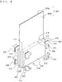
- FIG. 3 is a perspective view of a preliminary battery case to which a fixing jig according to a second embodiment is added.
- the preliminary battery case 200 includes a first case 200a and a second case 200b, outer peripheries of which are sealed by thermal fusion, and each of the first case 200a and the second case 200b has an electrode assembly receiving portion 210 formed therein.
- a method of decompressing the preliminary battery case into a vacuum state may be used.
- the preliminary battery case may be deformed while being contracted. Such deformation may occur the most greatly at a first side outer periphery 211 of the electrode assembly receiving portion, which is oriented in a direction in which gas is discharged.
- the other outer peripheries are deformed although there is a difference in degree.
- a third side outer periphery 203 may be deformed more than a second side outer periphery 202 and a fourth side outer periphery 204, since the third side outer periphery is an outer periphery in a major-axis direction of an electrode assembly.
- FIG. 3 shows the state in which fixing jigs are further disposed at each corner portion 212 of opposite ends of the third side outer periphery 203 of the electrode assembly receiving portion, which is opposite the first side outer periphery 211 of the electrode assembly receiving portion, i.e. the fixing jigs 220 are attached to all corner portions of the bottom surface of the electrode assembly receiving portion.
- the fixing jigs 220 are attached to all of the corner portions 212, as described above, it is possible to prevent deformation of the second side outer periphery to the fourth side outer periphery as well as the first side outer periphery.
- the fixing jig 220 shown in FIG. 3 is different from the fixing jig 110 of FIG. 2 in that the planar shape of the portion of the fixing jig that is added to the bottom surface of the electrode assembly receiving portion is not a quadrangular shape but is a " ⁇ " shape.
- the fixing jig 220 further includes an extension portion 222 not only configured to wrap the corner portion 212 but also extending to a resealing prearrangement portion 214, whereby the fixing jig is formed so as to have a size and shape corresponding respectively to the sizes and shapes of the corner portion 212 and the resealing prearrangement portion 214 extending from the corner portion.
- the fixing jig 220 is used, therefore, it is possible to additionally prevent deformation of a connection portion between a side wall 215 of the electrode assembly receiving portion and the resealing prearrangement portion 214.
- FIG. 4 is a perspective view of a preliminary battery case to which a fixing jig according to each of a third embodiment and a fourth embodiment is added.
- the fixing jig 320 shown in FIG. 4(a) is configured such that the portion of the fixing jig oriented in an x-axis direction, which is a major-axis direction of an electrode assembly receiving portion, is longer than the portion of the fixing jig oriented in a y-axis direction, which is a minor-axis direction of the electrode assembly receiving portion, compared to the fixing jig 220 of FIG. 3 .
- the length of the fixing jig attached to the portion of the preliminary battery case that is further deformed is increased, whereby it is possible to improve the effect of preventing deformation of the preliminary battery case.
- the fixing jig 420 shown in FIG. 4(b) is configured such that the planar shape of the portion of the fixing jig that wraps the bottom surface of an electrode assembly receiving portion is a triangular shape. In consideration of the fact that deformation of a corner portion of the electrode assembly receiving portion generally occurs at a side wall of the electrode assembly receiving portion, it is possible to achieve a desired effect even in the case in which a structure like the fixing jig 420 is used.
- Each of the fixing jigs 320 and 420 shown in FIG. 4 includes no extension portion extending to an outer peripheral sealing portion of the electrode assembly receiving portion. Of course, however, an extension portion may be included, unlike what is shown.
- FIG. 5 is a plan view of FIG. 4(b)
- FIG. 6 is a partial sectional view of FIG. 4 .
- the preliminary battery case 400 is configured such that gas is discharged in a direction indicated by arrows and the fixing jigs 420 are disposed at each corner portion of opposite ends of a first side outer periphery 411 of the electrode assembly receiving portion oriented in the direction in which the gas is discharged.
- the corner portion may be stably fixed to the inner surface of the fixing jig 420 in tight contact therewith in the state in which the corner portion is flat.
- a method of adding the adhesive material to the inner surface of the fixing jig is not particularly restricted.
- an adhesive may be applied to the inner surface of the fixing jig, an adhesive film may be attached to the inner surface of the fixing jig, or an adhesive material may be sprayed onto the fixing jig.
- FIG. 7 is a perspective view of a fixing jig according to each of a fifth embodiment and a sixth embodiment.
- FIG. 7(a) shows a fixing jig 520 having suction pads 521 attached to the inner surface thereof
- FIG. 7(b) shows a fixing jig 620 having suction holes 621 formed therein
- FIG. 7(c) shows the state of the fixing jig 620 when viewed from outside.
- the fixing jig 520 may suction the outer surface of the corner portion without a separate adhesive material, whereby the corner portion may be maintained attached to the inside of the fixing jig.
- a suction device 622 is added to the outside of the fixing jig 620.
- the suction device 622 When the suction device 622 is operated in the state in which the fixing jig 620 is attached to the outer surface of the corner portion, air is suctioned through the suction holes 621, whereby the outer surface of the corner portion may be maintained attached to the inner surface of the fixing jig.
- the operation of the suction device 622 is stopped after a pouch-shaped battery cell is completed, force suctioning the corner portion is released, whereby it is possible to remove the fixing jig from the corner portion.
- FIG. 8 is a perspective view of a preliminary battery case to which a fixing jig according to a seventh embodiment is added.
- the fixing jig 720 is formed so as to extend long along a first side outer periphery 711 of an electrode assembly receiving portion 710 including corner portions of opposite ends of the first side outer periphery 711 of the electrode assembly receiving portion.
- the fixing jig 720 shown in FIG. 8 includes an extension portion 722 extending to a sealing prearrangement portion so as to wrap the corner portions.
- the fixing jig may include no extending portion.
- the method of manufacturing the pouch-shaped battery cell according to the present invention includes a process of removing the fixing jig from the battery case after step (f).
- the adhesive material be removed from the outer surface of the battery case together with the fixing jig.
- a pouch-shaped battery cell is manufactured in the state in which a corner portion of an electrode assembly receiving portion is in tight contact with the inner surface of a fixing jig. Consequently, the shape of the corner portion brought into tight contact with the fixing jig may be maintained in a process of discharging an electrolytic solution and gas, a process of resealing an outer periphery of a preliminary battery case, and a process of removing an end of the outer periphery of a preliminary battery case.
- an adhesive material may be added to the inner surface of the fixing jig, whereby the outer surface of the corner portion may be maintained in tight contact with the inner surface of the fixing jig.
- suction pads may be added to the inner surface of the fixing jig or a suction device may be added to the fixing jig in order to suction the corner portion. Even in the case in which the preliminary battery case is contracted due to vacuum decompression, therefore, the state in which the corner portion is in tight contact with the inner surface of the fixing jig may be maintained.
- the shape of the corner portion is supported by the fixing jig such that the shape of the preliminary battery case when the electrode assembly receiving portion is formed in the preliminary battery case is maintained, as described above, it is possible to prevent the preliminary battery case from being crumpled or cracked in a process of manufacturing the pouch-shaped battery cell.
Abstract
Description
- This application claims the benefit of priority to
Korean Patent Application No. 2019-0162510 filed on December 9, 2019 - The present invention relates to a method of manufacturing a pouch-shaped battery cell using a fixing jig and a pouch-shaped battery cell manufactured using the same, and more particularly to a method of manufacturing a pouch-shaped battery cell using a fixing jig capable of manufacturing the pouch-shaped battery cell in the state in which the portion of the pouch-shaped battery cell that may be the most greatly deformed in a process of manufacturing the pouch-shaped battery cell is in tight contact with a fixing jig so as to be fixed by the fixing jig, whereby it is possible to remarkably reduce a battery cell defect rate, and a pouch-shaped battery cell manufactured using the same.
- Based on the shape of a case, a lithium secondary battery is classified as a cylindrical battery, a prismatic battery, or a pouch-shaped battery. Each of the cylindrical battery and the prismatic battery is a battery having an electrode assembly mounted in a metal can, and the pouch-shaped battery is a battery having an electrode assembly mounted in a pouch-shaped case generally made of an aluminum laminate sheet. Among these batteries, the pouch-shaped battery, which can be stacked with high integration, has high energy density per unit weight, is inexpensive, and can be easily modified, has attracted considerable attention in recent years.
- The laminate sheet includes an outer coating layer configured to secure insulation thereof and to protect the surface thereof, a metal layer configured to block gas and moisture and to allow a battery case to be easily formed, and an inner resin layer for adhesion.
- In general, a process of forming an electrode assembly receiving portion, a degassing process, and a process of sealing the outer periphery of the battery case are performed in order to manufacture the pouch-shaped battery. While the above processes are performed, the metal layer of the laminate sheet may be damaged. In particular, stress is concentrated on corner portions of the electrode assembly receiving portion, in which the electrode assembly is received. As a result, there is a high possibility of cracks being formed at the corner portions of the electrode assembly receiving portion.
- In the case in which cracks are formed at the laminate sheet, as described above, an electrolytic solution may leak out of the battery, or external moisture may be introduced into the battery. Leakage of the electrolytic solution may induce ignition due to high-voltage ground fault current, whereby safety of the battery may be reduced.
- In connection therewith,
Patent Document 1 discloses a crumple prevention portion formed at a sealing block used in a process of manufacturing a pouch-shaped secondary battery. InPatent Document 1, the sealing block, at which the crumple prevention portion is formed, is used to form sealing portions at outer peripheral corner portions of an electrode assembly receiving portion. It is possible to prevent crumples from being formed at the corner portions of the electrode assembly receiving portion by the provision of the sealing portions. - Patent Document 2 discloses a pouch-shaped battery case configured such that, among outer peripheral sealing portions of a concave portion configured to receive an electrode assembly, a non-sealing portion is formed at the outer periphery through which an electrolytic solution is infused and gas is discharged, wherein ends of the outer periphery through which gas is discharged, excluding a central portion thereof, are sealed in advance.
- In
Patent Document 1 and Patent Document 2, the sealing portions are formed in advance as structures for preventing crumples from being formed at the corner portions or the ends of the outer peripheries in the early stage of manufacture of the battery case. However, it is difficult to prevent the corner portions from being deformed by stress repeatedly concentrated thereon in subsequent degassing and resealing processes. - Therefore, there is a high necessity for technology capable of preventing corner portions of an electrode assembly receiving portion from being deformed or cracked by force continuously applied to the corner portions while a process of manufacturing a pouch-shaped battery cell is performed.
-
- (Patent Document 1)
Korean Patent Application Publication No. 2019-0042801 (2019.04.25 - (Patent Document 2)
Korean Patent Application Publication No. 2019-0042800 (2019.04.25 - The present invention has been made in view of the above problems, and it is an object of the present invention to provide a method of manufacturing a pouch-shaped battery cell using a fixing jig capable of preventing deformation of corner portions of an electrode assembly receiving portion and maintaining the initial shape of the corner portions in a process of manufacturing the pouch-shaped battery cell and a pouch-shaped battery cell manufactured using the same.
- In order to accomplish the above object, a method of manufacturing a pouch-shaped battery cell according to the present invention includes (a) forming an electrode assembly receiving portion in a laminate sheet to manufacture a preliminary battery case, (b) receiving an electrode assembly in the electrode assembly receiving portion and sealing other outer peripheries of the preliminary battery case excluding a first side outer periphery of the preliminary battery case, through which gas is discharged, (c) disposing a fixing jig at each corner portion of opposite ends of a first side outer periphery of the electrode assembly receiving portion, (d) performing an activation process and a degassing process, (e) resealing the first side outer periphery of the electrode assembly receiving portion, and (f) removing an end of the preliminary battery case, wherein step (d) to step (f) are performed in the state in which the corner portion is in tight contact with the inner surface of the fixing jig.
- The corner portion may be a portion at which the bottom surface of the electrode assembly receiving portion and two adjacent side surfaces of the electrode assembly receiving portion are joined to each other, and the fixing jig may have a structure configured to wrap the corner portion.
- The fixing jig may extend to a resealing prearrangement portion of step (e) so as to wrap the resealing prearrangement portion.
- In a concrete example, an adhesive material may be added to the inner surface of the fixing jig such that the corner portion is attached to the inner surface of the fixing jig.
- In addition, the adhesive material may be added to the fixing jig by applying an adhesive to the fixing jig, attaching an adhesive film to the fixing jig, or spraying an adhesive material onto the fixing jig.
- In another concrete example, the fixing jig may include a suction portion configured to suction the corner portion.
- Specifically, the suction portion may include a suction pad.
- Alternatively, the suction portion may include a suction device.
- In addition, a fixing jig may be further disposed at each corner portion of opposite ends of a third side outer periphery of the electrode assembly receiving portion, the third side outer periphery being opposite the first side outer periphery.
- Alternatively, the fixing jig may be disposed along the first side outer periphery of the electrode assembly receiving portion comprising the corner portions of the opposite ends of the first side outer periphery.
- The method may include a process of temporarily sealing the first side outer periphery of the preliminary battery case before the activation process of step (d) is performed.
- The present invention provides a pouch-shaped battery cell manufactured using the method of manufacturing the pouch-shaped battery cell and a battery module including the pouch-shaped battery cell.
-
-
FIG. 1 is a view showing a process of manufacturing a pouch-shaped battery cell according to the present invention. -
FIG. 2 is a perspective view of a preliminary battery case to which a fixing jig according to a first embodiment is added. -
FIG. 3 is a perspective view of a preliminary battery case to which a fixing jig according to a second embodiment is added. -
FIG. 4 is a perspective view of a preliminary battery case to which a fixing jig according to each of a third embodiment and a fourth embodiment is added. -
FIG. 5 is a plan view ofFIG. 4(b) . -
FIG. 6 is a partial sectional view ofFIG. 4 . -
FIG. 7 is a perspective view of a fixing jig according to each of a fifth embodiment and a sixth embodiment. -
FIG. 8 is a perspective view of a preliminary battery case to which a fixing jig according to a seventh embodiment is added. - Now, preferred embodiments of the present invention will be described in detail with reference to the accompanying drawings such that the preferred embodiments of the present invention can be easily implemented by a person having ordinary skill in the art to which the present invention pertains. In describing the principle of operation of the preferred embodiments of the present invention in detail, however, a detailed description of known functions and configurations incorporated herein will be omitted when the same may obscure the subject matter of the present invention.
- In addition, the same reference numbers will be used throughout the drawings to refer to parts that perform similar functions or operations. In the case in which one part is said to be connected to another part in the specification, not only may the one part be directly connected to the other part, but also, the one part may be indirectly connected to the other part via a further part. In addition, that a certain element is included does not mean that other elements are excluded, but means that such elements may be further included unless mentioned otherwise.
- A description to embody elements through limitation or addition may be applied to all inventions, unless particularly restricted, and does not limit a specific invention.
- Hereinafter, embodiments of the present invention will be described in detail with reference to the accompanying drawings.
-
FIG. 1 is a view showing a process of manufacturing a pouch-shaped battery cell according to the present invention. - Referring to
FIG. 1 , in order to manufacture a pouch-shaped battery cell according to the present invention, first, a laminate sheet is pressed using apunch 10 in the state of being placed on a die (not shown) to form an electrodeassembly receiving portion 110. Anelectrode assembly 105 is received in the electrodeassembly receiving portion 110, and a second sideouter periphery 102, a third sideouter periphery 103, and a fourth sideouter periphery 104 of apreliminary battery case 100 excluding a first sideouter periphery 101 of the preliminary battery case, through which gas is discharged, are sealed. -
Fixing jigs 120 are disposed at eachcorner portion 112 of opposite ends of a first sideouter periphery 111 of the electrodeassembly receiving portion 110, the first sideouter periphery 101 of thepreliminary battery case 100 is temporarily sealed, and an activation process and a degassing process are performed. - Subsequently, the first side
outer periphery 111 of the electrodeassembly receiving portion 110 is resealed, and the end outside the first sideouter periphery 111 is removed to manufacture a pouch-shaped battery cell. - After the pouch-shaped battery cell is completed, as described above, the
fixing jigs 120 are removed from the corner portions of the opposite ends of the first sideouter periphery 111 of the electrode assembly receiving portion. - Each of the corner portions is a portion at which the bottom surface of the electrode assembly receiving portion and two adjacent side surfaces of the electrode assembly receiving portion are joined to each other. The corner portion mentioned in this specification refers to the same portion as the above mentioned portion.
- Each of the fixing jigs has a structure configured to wrap a corresponding one of the corner portions. The outer surface of the corner portion at which the fixing jig is disposed may be maintained in tight contact with the inner surface of the fixing jig.
-
FIG. 2 is a perspective view of a preliminary battery case to which a fixing jig according to a first embodiment is added. - Referring to
FIG. 2 , fixingjigs 120 are disposed at oppositeend corner portions 112 of a first sideouter periphery 111 of an electrodeassembly receiving portion 110. - The inner surface of each of the fixing
jigs 120 is formed so as to have a size and shape corresponding respectively to the size and shape of a corresponding one of thecorner portions 112. The inner surface of the fixingjig 120 and the outer surface of thecorner portion 112 are completely brought into tight contact with each other. - Even in the case in which external force is applied to the preliminary battery case to the extent to which the preliminary battery case is contracted or twisted in a process of manufacturing a pouch-shaped battery cell, therefore, the corner portion is maintained attached to the inner surface of the fixing jig in tight contact therewith. Consequently, it is possible to prevent the corner portion from being crumpled or cracked.
-
FIG. 3 is a perspective view of a preliminary battery case to which a fixing jig according to a second embodiment is added. - Referring to
FIG. 3 , thepreliminary battery case 200 includes afirst case 200a and asecond case 200b, outer peripheries of which are sealed by thermal fusion, and each of thefirst case 200a and thesecond case 200b has an electrodeassembly receiving portion 210 formed therein. - Also, in a degassing process, which is included in a process of manufacturing a pouch-shaped battery cell, a method of decompressing the preliminary battery case into a vacuum state may be used. At this time, the preliminary battery case may be deformed while being contracted. Such deformation may occur the most greatly at a first side
outer periphery 211 of the electrode assembly receiving portion, which is oriented in a direction in which gas is discharged. However, the other outer peripheries are deformed although there is a difference in degree. - In particular, a third side
outer periphery 203 may be deformed more than a second sideouter periphery 202 and a fourth sideouter periphery 204, since the third side outer periphery is an outer periphery in a major-axis direction of an electrode assembly. - Therefore,
FIG. 3 shows the state in which fixing jigs are further disposed at eachcorner portion 212 of opposite ends of the third sideouter periphery 203 of the electrode assembly receiving portion, which is opposite the first sideouter periphery 211 of the electrode assembly receiving portion, i.e. the fixingjigs 220 are attached to all corner portions of the bottom surface of the electrode assembly receiving portion. In the case in which the fixingjigs 220 are attached to all of thecorner portions 212, as described above, it is possible to prevent deformation of the second side outer periphery to the fourth side outer periphery as well as the first side outer periphery. - The fixing
jig 220 shown inFIG. 3 is different from the fixingjig 110 ofFIG. 2 in that the planar shape of the portion of the fixing jig that is added to the bottom surface of the electrode assembly receiving portion is not a quadrangular shape but is a "¬ " shape. - In addition, the fixing
jig 220 further includes anextension portion 222 not only configured to wrap thecorner portion 212 but also extending to aresealing prearrangement portion 214, whereby the fixing jig is formed so as to have a size and shape corresponding respectively to the sizes and shapes of thecorner portion 212 and theresealing prearrangement portion 214 extending from the corner portion. In the case in which the fixingjig 220 is used, therefore, it is possible to additionally prevent deformation of a connection portion between aside wall 215 of the electrode assembly receiving portion and theresealing prearrangement portion 214. -
FIG. 4 is a perspective view of a preliminary battery case to which a fixing jig according to each of a third embodiment and a fourth embodiment is added. - Referring to
FIG. 4 , the fixingjig 320 shown inFIG. 4(a) is configured such that the portion of the fixing jig oriented in an x-axis direction, which is a major-axis direction of an electrode assembly receiving portion, is longer than the portion of the fixing jig oriented in a y-axis direction, which is a minor-axis direction of the electrode assembly receiving portion, compared to the fixingjig 220 ofFIG. 3 . - In consideration of the fact that the major-axis direction outer periphery of the electrode assembly receiving portion is deformed more than the minor-axis direction outer periphery of the electrode assembly receiving portion, the length of the fixing jig attached to the portion of the preliminary battery case that is further deformed is increased, whereby it is possible to improve the effect of preventing deformation of the preliminary battery case.
- The fixing
jig 420 shown inFIG. 4(b) is configured such that the planar shape of the portion of the fixing jig that wraps the bottom surface of an electrode assembly receiving portion is a triangular shape. In consideration of the fact that deformation of a corner portion of the electrode assembly receiving portion generally occurs at a side wall of the electrode assembly receiving portion, it is possible to achieve a desired effect even in the case in which a structure like the fixingjig 420 is used. - Each of the fixing
jigs FIG. 4 includes no extension portion extending to an outer peripheral sealing portion of the electrode assembly receiving portion. Of course, however, an extension portion may be included, unlike what is shown. -
FIG. 5 is a plan view ofFIG. 4(b) , andFIG. 6 is a partial sectional view ofFIG. 4 . - Referring to
FIGS. 5 and6 , thepreliminary battery case 400 is configured such that gas is discharged in a direction indicated by arrows and the fixingjigs 420 are disposed at each corner portion of opposite ends of a first sideouter periphery 411 of the electrode assembly receiving portion oriented in the direction in which the gas is discharged. - Since an
adhesive material 421 is added to the inner surface of the fixingjig 420, the corner portion may be stably fixed to the inner surface of the fixingjig 420 in tight contact therewith in the state in which the corner portion is flat. - A method of adding the adhesive material to the inner surface of the fixing jig is not particularly restricted. For example, an adhesive may be applied to the inner surface of the fixing jig, an adhesive film may be attached to the inner surface of the fixing jig, or an adhesive material may be sprayed onto the fixing jig.
-
FIG. 7 is a perspective view of a fixing jig according to each of a fifth embodiment and a sixth embodiment. - Referring to
FIG. 7, FIG. 7(a) shows a fixingjig 520 havingsuction pads 521 attached to the inner surface thereof,FIG. 7(b) shows a fixingjig 620 havingsuction holes 621 formed therein, andFIG. 7(c) shows the state of the fixingjig 620 when viewed from outside. - In the case in which the fixing
jig 520 is attached to the outer surface of the corner portion, the fixing jig may suction the outer surface of the corner portion without a separate adhesive material, whereby the corner portion may be maintained attached to the inside of the fixing jig. - A
suction device 622 is added to the outside of the fixingjig 620. When thesuction device 622 is operated in the state in which the fixingjig 620 is attached to the outer surface of the corner portion, air is suctioned through the suction holes 621, whereby the outer surface of the corner portion may be maintained attached to the inner surface of the fixing jig. When the operation of thesuction device 622 is stopped after a pouch-shaped battery cell is completed, force suctioning the corner portion is released, whereby it is possible to remove the fixing jig from the corner portion. -
FIG. 8 is a perspective view of a preliminary battery case to which a fixing jig according to a seventh embodiment is added. - Referring to
FIG. 8 , the fixingjig 720 is formed so as to extend long along a first sideouter periphery 711 of an electrodeassembly receiving portion 710 including corner portions of opposite ends of the first sideouter periphery 711 of the electrode assembly receiving portion. - Consequently, it is possible to improve the effect of preventing deformation of the first side outer periphery, which is greatly deformed in a process of manufacturing a pouch-shaped battery cell.
- The fixing
jig 720 shown inFIG. 8 includes anextension portion 722 extending to a sealing prearrangement portion so as to wrap the corner portions. Of course, however, the fixing jig may include no extending portion. - The method of manufacturing the pouch-shaped battery cell according to the present invention includes a process of removing the fixing jig from the battery case after step (f). In the case in which an adhesive material is attached to the inner surface of the fixing jig, it is preferable that the adhesive material be removed from the outer surface of the battery case together with the fixing jig.
- Meanwhile, in the case in which suction pads are attached to the inner surface of the fixing jig or in the case in which a suction device is added to the outside of the fixing jig, it is possible to remove the fixing jig while no adhesive material remains on the outer surface of the pouch-shaped battery cell.
- In the method of manufacturing the pouch-shaped battery cell according to the present invention and the pouch-shaped battery cell manufactured using the same, as described above, it is possible to prevent cracks from being formed at the corner portion of the electrode assembly receiving portion during the manufacturing process, whereby it is possible to reduce a battery cell defect rate and at the same time to prevent a possibility of ignition due to infusion of an electrolytic solution.
- Those skilled in the art to which the present invention pertains will appreciate that various applications and modifications are possible within the category of the present invention based on the above description.
-
- 10: Punch
- 100, 200, 400: Preliminary battery cases
- 101: First side outer periphery of preliminary battery case
- 102, 202: Second side outer peripheries
- 103, 203: Third side outer peripheries
- 104, 204: Fourth side outer peripheries
- 105: Electrode assembly
- 110, 210, 710: Electrode assembly receiving portions
- 111, 211, 411, 711: First side outer peripheries of electrode assembly receiving portions
- 112, 212: Corner portions
- 120, 220, 320, 420, 520, 620, 720: Fixing jigs
- 200a: First case
- 200b: Second case
- 214: Resealing prearrangement portion
- 215: Side wall of electrode assembly receiving portion
- 222, 722: Extension portions
- 421: Adhesive material
- 521: Suction pads
- 621: Suction holes
- 622: Suction device
- As is apparent from the above description, in the present invention, a pouch-shaped battery cell is manufactured in the state in which a corner portion of an electrode assembly receiving portion is in tight contact with the inner surface of a fixing jig. Consequently, the shape of the corner portion brought into tight contact with the fixing jig may be maintained in a process of discharging an electrolytic solution and gas, a process of resealing an outer periphery of a preliminary battery case, and a process of removing an end of the outer periphery of a preliminary battery case.
- In addition, an adhesive material may be added to the inner surface of the fixing jig, whereby the outer surface of the corner portion may be maintained in tight contact with the inner surface of the fixing jig.
- In addition, suction pads may be added to the inner surface of the fixing jig or a suction device may be added to the fixing jig in order to suction the corner portion. Even in the case in which the preliminary battery case is contracted due to vacuum decompression, therefore, the state in which the corner portion is in tight contact with the inner surface of the fixing jig may be maintained.
- Since the shape of the corner portion is supported by the fixing jig such that the shape of the preliminary battery case when the electrode assembly receiving portion is formed in the preliminary battery case is maintained, as described above, it is possible to prevent the preliminary battery case from being crumpled or cracked in a process of manufacturing the pouch-shaped battery cell.
- Consequently, it is possible to reduce a pouch-shaped battery cell defect rate and to reduce a danger of ignition due to ground fault current, which may be induced by leakage of the electrolytic solution.
Claims (13)
- A method of manufacturing a pouch-shaped battery cell, the method comprising:(a) forming an electrode assembly receiving portion in a laminate sheet to manufacture a preliminary battery case;(b) receiving an electrode assembly in the electrode assembly receiving portion and sealing other outer peripheries of the preliminary battery case excluding a first side outer periphery of the preliminary battery case, through which gas is discharged;(c) disposing a fixing jig at each corner portion of opposite ends of a first side outer periphery of the electrode assembly receiving portion;(d) performing an activation process and a degassing process;(e) resealing the first side outer periphery of the electrode assembly receiving portion; and(f) removing an end of the preliminary battery case, wherein
step (d) to step (f) are performed in a state in which the corner portion is in tight contact with an inner surface of the fixing jig. - The method according to claim 1, whereinthe corner portion is a portion at which a bottom surface of the electrode assembly receiving portion and two adjacent side surfaces of the electrode assembly receiving portion are joined to each other, andthe fixing jig has a structure configured to wrap the corner portion.
- The method according to claim 2, wherein the fixing jig extends to a resealing prearrangement portion of step (e) so as to wrap the resealing prearrangement portion.
- The method according to claim 1, wherein an adhesive material is added to the inner surface of the fixing jig such that the corner portion is attached to the inner surface of the fixing jig.
- The method according to claim 4, wherein the adhesive material is added to the fixing jig by applying an adhesive to the fixing jig, attaching an adhesive film to the fixing jig, or spraying an adhesive material onto the fixing jig.
- The method according to claim 1, wherein the fixing jig comprises a suction portion configured to suction the corner portion.
- The method according to claim 6, wherein the suction portion includes a suction pad.
- The method according to claim 6, wherein the suction portion includes a suction device.
- The method according to claim 1, wherein a fixing jig is further disposed at each corner portion of opposite ends of a third side outer periphery of the electrode assembly receiving portion, the third side outer periphery being opposite the first side outer periphery.
- The method according to claim 1, wherein the fixing jig is disposed along the first side outer periphery of the electrode assembly receiving portion comprising the corner portions of the opposite ends of the first side outer periphery.
- The method according to claim 1, comprising a process of temporarily sealing the first side outer periphery of the preliminary battery case before the activation process of step (d) is performed.
- A pouch-shaped battery cell manufactured using the method according to any one of claims 1 to 11.
- A battery module comprising the pouch-shaped battery cell according to claim 12.
Applications Claiming Priority (2)
| Application Number | Priority Date | Filing Date | Title |
|---|---|---|---|
| KR1020190162510A KR20210072316A (en) | 2019-12-09 | 2019-12-09 | Method for Preparing Pouch-type Battery Cell Using Fixing Jig and Pouch-type Battery Cell Manufactured therewith |
| PCT/KR2020/095130 WO2021118331A1 (en) | 2019-12-09 | 2020-10-29 | Method for manufacturing pouch-type battery cell by using retaining jig, and pouch-type battery cell manufactured using same |
Publications (2)
| Publication Number | Publication Date |
|---|---|
| EP4007044A1 true EP4007044A1 (en) | 2022-06-01 |
| EP4007044A4 EP4007044A4 (en) | 2022-11-16 |
Family
ID=76330256
Family Applications (1)
| Application Number | Title | Priority Date | Filing Date |
|---|---|---|---|
| EP20898634.9A Pending EP4007044A4 (en) | 2019-12-09 | 2020-10-29 | Method for manufacturing pouch-type battery cell by using retaining jig, and pouch-type battery cell manufactured using same |
Country Status (4)
| Country | Link |
|---|---|
| EP (1) | EP4007044A4 (en) |
| KR (1) | KR20210072316A (en) |
| CN (1) | CN114175333B (en) |
| WO (1) | WO2021118331A1 (en) |
Family Cites Families (12)
| Publication number | Priority date | Publication date | Assignee | Title |
|---|---|---|---|---|
| KR101108447B1 (en) * | 2006-08-28 | 2012-02-08 | 주식회사 엘지화학 | Process for Preparation of Pouch-typed Secondary Battery Having Excellent Sealing Property |
| CN102709600B (en) * | 2012-01-12 | 2016-11-16 | 宁德新能源科技有限公司 | A kind of method preventing flexible packing lithium ion battery angle bit loss wound |
| KR20130113301A (en) * | 2012-04-05 | 2013-10-15 | 주식회사 엘지화학 | Battery cell of stair-like structure |
| CN203300708U (en) * | 2013-02-01 | 2013-11-20 | 广东国光电子有限公司 | Soft-packed PLIB (polymer lithium ion battery) |
| CN203398168U (en) * | 2013-07-09 | 2014-01-15 | 曙鹏科技(深圳)有限公司 | Soft package lithium ion battery |
| KR102028082B1 (en) * | 2016-01-20 | 2019-11-14 | 주식회사 엘지화학 | Preparation apparatus and method of battery cell |
| KR102123078B1 (en) * | 2016-05-24 | 2020-06-15 | 주식회사 엘지화학 | Manufacturin method of rechargeable battery |
| KR102183772B1 (en) * | 2016-12-22 | 2020-11-27 | 주식회사 엘지화학 | Process for Preparation of Pouch-typed Battery Cell Using Member for Preventing Electrolyte Leakage |
| KR102261672B1 (en) * | 2017-04-24 | 2021-06-08 | 주식회사 엘지에너지솔루션 | Battery Case Having Anti-Curl Guideline and Apparatus thereor |
| KR102347884B1 (en) * | 2017-10-17 | 2022-01-06 | 주식회사 엘지에너지솔루션 | Sealing Block to Prevent Crack of Pouch-Type Secondary Battery, Pouch-Type Battery Case and Sealing Method for Pouch-Type Battery Case Using thereof |
| KR102347901B1 (en) | 2017-10-17 | 2022-01-06 | 주식회사 엘지에너지솔루션 | Pouch-Type Battery Case Having Structure to Prevent Crack and Method for Preparing the Same |
| WO2019117558A1 (en) * | 2017-12-15 | 2019-06-20 | 주식회사 엘지화학 | Method for manufacturing secondary battery |
-
2019
- 2019-12-09 KR KR1020190162510A patent/KR20210072316A/en unknown
-
2020
- 2020-10-29 WO PCT/KR2020/095130 patent/WO2021118331A1/en unknown
- 2020-10-29 CN CN202080053435.6A patent/CN114175333B/en active Active
- 2020-10-29 EP EP20898634.9A patent/EP4007044A4/en active Pending
Also Published As
| Publication number | Publication date |
|---|---|
| CN114175333A (en) | 2022-03-11 |
| WO2021118331A1 (en) | 2021-06-17 |
| KR20210072316A (en) | 2021-06-17 |
| CN114175333B (en) | 2023-11-24 |
| EP4007044A4 (en) | 2022-11-16 |
| US20220407105A1 (en) | 2022-12-22 |
Similar Documents
| Publication | Publication Date | Title |
|---|---|---|
| JP6742401B2 (en) | Gaskets and diaphragms for electrochemical cells | |
| US11189860B2 (en) | Method of manufacturing secondary battery | |
| JP5690308B2 (en) | Pouch type secondary battery and manufacturing method thereof | |
| US10862099B2 (en) | Apparatus for enhancing electrolyte wetting in rechargeable battery and electrolyte wetting enhancing method using the same | |
| KR102217443B1 (en) | Gas removal device and gas removal method for rechargeable battery | |
| EP4040579A1 (en) | Method for manufacturing pouch-type battery cell using protection film and pouch-type battery cell manufactured using same | |
| KR102394494B1 (en) | System and method for producing secondary battery | |
| JP2009004361A (en) | Laminated battery | |
| EP3637492A1 (en) | Pouch-type secondary battery sealing block for preventing cracks, pouch-type battery case manufactured by using same, and sealing method for pouch-type battery case | |
| KR102235282B1 (en) | Fablicating method of rechargeable battery having a curved surface | |
| EP4007044A1 (en) | Method for manufacturing pouch-type battery cell by using retaining jig, and pouch-type battery cell manufactured using same | |
| JP2007141774A (en) | Manufacturing method of storage element | |
| KR102326441B1 (en) | Sealing device and sealing method of pouch for secondary battery | |
| KR20220065707A (en) | Method of manufacturing pouch-type battery cell comprising two-times sealing and pouch-type battery cell manufactured thereby | |
| US11973175B2 (en) | Method of manufacturing pouch-shaped battery cell using fixing jig and pouch-shaped battery cell manufactured using the same | |
| US20130344372A1 (en) | Stress relief body to prevent cell seal failure during assembly | |
| US11171352B2 (en) | Assembly device for battery component | |
| JP4403858B2 (en) | Manufacturing method and manufacturing apparatus for secondary battery or electric double layer capacitor | |
| WO2021181893A1 (en) | Gas discharge valve of battery and battery | |
| KR102124947B1 (en) | Method of manufacturing electrode assembly | |
| US20220407198A1 (en) | Electrolyte Injection Device and Electrolyte Injection Method Using the Same | |
| US20220407152A1 (en) | Pouch Type Secondary Battery, Battery Pack, and Method for Manufacturing Pouch Type Secondary Battery | |
| JP6119573B2 (en) | Method for manufacturing power storage device | |
| US20220384922A1 (en) | Electrode Assembly, Secondary Battery and Method for Manufacturing the Same | |
| CN112136240A (en) | Battery with a battery cell |
Legal Events
| Date | Code | Title | Description |
|---|---|---|---|
| STAA | Information on the status of an ep patent application or granted ep patent |
Free format text: STATUS: THE INTERNATIONAL PUBLICATION HAS BEEN MADE |
|
| PUAI | Public reference made under article 153(3) epc to a published international application that has entered the european phase |
Free format text: ORIGINAL CODE: 0009012 |
|
| STAA | Information on the status of an ep patent application or granted ep patent |
Free format text: STATUS: REQUEST FOR EXAMINATION WAS MADE |
|
| 17P | Request for examination filed |
Effective date: 20220223 |
|
| AK | Designated contracting states |
Kind code of ref document: A1 Designated state(s): AL AT BE BG CH CY CZ DE DK EE ES FI FR GB GR HR HU IE IS IT LI LT LU LV MC MK MT NL NO PL PT RO RS SE SI SK SM TR |
|
| A4 | Supplementary search report drawn up and despatched |
Effective date: 20221014 |
|
| RIC1 | Information provided on ipc code assigned before grant |
Ipc: H01M 10/058 20100101ALI20221010BHEP Ipc: H01M 10/0525 20100101ALI20221010BHEP Ipc: H01M 50/105 20210101ALI20221010BHEP Ipc: H01M 50/121 20210101ALI20221010BHEP Ipc: H01M 50/117 20210101ALI20221010BHEP Ipc: H01M 50/124 20210101ALI20221010BHEP Ipc: B29L 31/00 20060101ALI20221010BHEP Ipc: B29C 51/26 20060101ALI20221010BHEP Ipc: H01M 4/04 20060101ALI20221010BHEP Ipc: H01M 10/44 20060101ALI20221010BHEP Ipc: H01M 50/10 20210101AFI20221010BHEP |
|
| DAV | Request for validation of the european patent (deleted) | ||
| DAX | Request for extension of the european patent (deleted) |