EP4016722A1 - Power storage module - Google Patents
Power storage module Download PDFInfo
- Publication number
- EP4016722A1 EP4016722A1 EP21209566.5A EP21209566A EP4016722A1 EP 4016722 A1 EP4016722 A1 EP 4016722A1 EP 21209566 A EP21209566 A EP 21209566A EP 4016722 A1 EP4016722 A1 EP 4016722A1
- Authority
- EP
- European Patent Office
- Prior art keywords
- straight portion
- power storage
- circuit board
- printed circuit
- flexible printed
- Prior art date
- Legal status (The legal status is an assumption and is not a legal conclusion. Google has not performed a legal analysis and makes no representation as to the accuracy of the status listed.)
- Pending
Links
- 210000000352 storage cell Anatomy 0.000 claims abstract description 7
- 239000011347 resin Substances 0.000 claims description 5
- 229920005989 resin Polymers 0.000 claims description 5
- 210000004027 cell Anatomy 0.000 description 18
- 238000005516 engineering process Methods 0.000 description 7
- 238000010586 diagram Methods 0.000 description 6
- 230000004048 modification Effects 0.000 description 3
- 238000012986 modification Methods 0.000 description 3
- 238000005452 bending Methods 0.000 description 2
- 239000003990 capacitor Substances 0.000 description 2
- 230000006835 compression Effects 0.000 description 2
- 238000007906 compression Methods 0.000 description 2
- 239000011888 foil Substances 0.000 description 2
- 238000009413 insulation Methods 0.000 description 2
- 229910052751 metal Inorganic materials 0.000 description 2
- 239000002184 metal Substances 0.000 description 2
- RYGMFSIKBFXOCR-UHFFFAOYSA-N Copper Chemical compound [Cu] RYGMFSIKBFXOCR-UHFFFAOYSA-N 0.000 description 1
- HBBGRARXTFLTSG-UHFFFAOYSA-N Lithium ion Chemical compound [Li+] HBBGRARXTFLTSG-UHFFFAOYSA-N 0.000 description 1
- 239000004642 Polyimide Substances 0.000 description 1
- 238000006243 chemical reaction Methods 0.000 description 1
- 239000004020 conductor Substances 0.000 description 1
- 239000011889 copper foil Substances 0.000 description 1
- 238000007599 discharging Methods 0.000 description 1
- 238000006073 displacement reaction Methods 0.000 description 1
- 230000000694 effects Effects 0.000 description 1
- 239000008151 electrolyte solution Substances 0.000 description 1
- 229910001416 lithium ion Inorganic materials 0.000 description 1
- 229910052987 metal hydride Inorganic materials 0.000 description 1
- 229920001721 polyimide Polymers 0.000 description 1
- 238000003466 welding Methods 0.000 description 1
Images


Classifications
-
- H—ELECTRICITY
- H01—ELECTRIC ELEMENTS
- H01M—PROCESSES OR MEANS, e.g. BATTERIES, FOR THE DIRECT CONVERSION OF CHEMICAL ENERGY INTO ELECTRICAL ENERGY
- H01M50/00—Constructional details or processes of manufacture of the non-active parts of electrochemical cells other than fuel cells, e.g. hybrid cells
- H01M50/20—Mountings; Secondary casings or frames; Racks, modules or packs; Suspension devices; Shock absorbers; Transport or carrying devices; Holders
- H01M50/204—Racks, modules or packs for multiple batteries or multiple cells
-
- H—ELECTRICITY
- H01—ELECTRIC ELEMENTS
- H01M—PROCESSES OR MEANS, e.g. BATTERIES, FOR THE DIRECT CONVERSION OF CHEMICAL ENERGY INTO ELECTRICAL ENERGY
- H01M50/00—Constructional details or processes of manufacture of the non-active parts of electrochemical cells other than fuel cells, e.g. hybrid cells
- H01M50/50—Current conducting connections for cells or batteries
- H01M50/502—Interconnectors for connecting terminals of adjacent batteries; Interconnectors for connecting cells outside a battery casing
- H01M50/503—Interconnectors for connecting terminals of adjacent batteries; Interconnectors for connecting cells outside a battery casing characterised by the shape of the interconnectors
-
- H—ELECTRICITY
- H01—ELECTRIC ELEMENTS
- H01M—PROCESSES OR MEANS, e.g. BATTERIES, FOR THE DIRECT CONVERSION OF CHEMICAL ENERGY INTO ELECTRICAL ENERGY
- H01M50/00—Constructional details or processes of manufacture of the non-active parts of electrochemical cells other than fuel cells, e.g. hybrid cells
- H01M50/20—Mountings; Secondary casings or frames; Racks, modules or packs; Suspension devices; Shock absorbers; Transport or carrying devices; Holders
- H01M50/284—Mountings; Secondary casings or frames; Racks, modules or packs; Suspension devices; Shock absorbers; Transport or carrying devices; Holders with incorporated circuit boards, e.g. printed circuit boards [PCB]
-
- H—ELECTRICITY
- H01—ELECTRIC ELEMENTS
- H01M—PROCESSES OR MEANS, e.g. BATTERIES, FOR THE DIRECT CONVERSION OF CHEMICAL ENERGY INTO ELECTRICAL ENERGY
- H01M50/00—Constructional details or processes of manufacture of the non-active parts of electrochemical cells other than fuel cells, e.g. hybrid cells
- H01M50/50—Current conducting connections for cells or batteries
- H01M50/502—Interconnectors for connecting terminals of adjacent batteries; Interconnectors for connecting cells outside a battery casing
- H01M50/505—Interconnectors for connecting terminals of adjacent batteries; Interconnectors for connecting cells outside a battery casing comprising a single busbar
-
- H—ELECTRICITY
- H01—ELECTRIC ELEMENTS
- H01M—PROCESSES OR MEANS, e.g. BATTERIES, FOR THE DIRECT CONVERSION OF CHEMICAL ENERGY INTO ELECTRICAL ENERGY
- H01M50/00—Constructional details or processes of manufacture of the non-active parts of electrochemical cells other than fuel cells, e.g. hybrid cells
- H01M50/50—Current conducting connections for cells or batteries
- H01M50/502—Interconnectors for connecting terminals of adjacent batteries; Interconnectors for connecting cells outside a battery casing
- H01M50/519—Interconnectors for connecting terminals of adjacent batteries; Interconnectors for connecting cells outside a battery casing comprising printed circuit boards [PCB]
-
- H—ELECTRICITY
- H05—ELECTRIC TECHNIQUES NOT OTHERWISE PROVIDED FOR
- H05K—PRINTED CIRCUITS; CASINGS OR CONSTRUCTIONAL DETAILS OF ELECTRIC APPARATUS; MANUFACTURE OF ASSEMBLAGES OF ELECTRICAL COMPONENTS
- H05K1/00—Printed circuits
- H05K1/02—Details
- H05K1/11—Printed elements for providing electric connections to or between printed circuits
- H05K1/118—Printed elements for providing electric connections to or between printed circuits specially for flexible printed circuits, e.g. using folded portions
-
- Y—GENERAL TAGGING OF NEW TECHNOLOGICAL DEVELOPMENTS; GENERAL TAGGING OF CROSS-SECTIONAL TECHNOLOGIES SPANNING OVER SEVERAL SECTIONS OF THE IPC; TECHNICAL SUBJECTS COVERED BY FORMER USPC CROSS-REFERENCE ART COLLECTIONS [XRACs] AND DIGESTS
- Y02—TECHNOLOGIES OR APPLICATIONS FOR MITIGATION OR ADAPTATION AGAINST CLIMATE CHANGE
- Y02E—REDUCTION OF GREENHOUSE GAS [GHG] EMISSIONS, RELATED TO ENERGY GENERATION, TRANSMISSION OR DISTRIBUTION
- Y02E60/00—Enabling technologies; Technologies with a potential or indirect contribution to GHG emissions mitigation
- Y02E60/10—Energy storage using batteries
Definitions
- the present technology relates to a power storage module.
- Japanese Utility Model Laying-Open No. 58-153468 is a prior art document that discloses a configuration of a flexible printed circuit board.
- a connection piece portion having straight extension portions having the same length are formed to extend in a meandering manner, the connection piece portion being provided with a conductor that connects a connection target component and a circuit pattern of the flexible printed circuit board to each other.
- connection piece portion of the flexible printed circuit board is constituted of the straight extension portions having the same length, there is room for attaining an efficient layout by attaining a small occupied area.
- An object of the present technology is to provide a power storage module in which an efficient layout can be attained in a connection piece portion of a flexible printed circuit board by attaining a small occupied area while securing a required fatigue life against stress generated in the event of vibration.
- a power storage module includes a stack, a resin plate, a flexible printed circuit board, and a connection terminal.
- a stack a plurality of power storage cells each including an electrode terminal are stacked in a stacking direction.
- the resin plate has a bottom surface portion extending in each of the stacking direction and a width direction orthogonal to the stacking direction, and is placed on the stack.
- the flexible printed circuit board is placed on the bottom portion, and has an electric circuit electrically connected to the plurality of power storage cells.
- the connection terminal is provided on the flexible printed circuit board and is electrically connected to the electrode terminal.
- the flexible printed circuit board has a main body portion, and a connection piece portion that extends from the main body portion and is curved so as to be connected to the connection terminal.
- connection piece portion includes a first straight portion extending straightly in the stacking direction, and a second straight portion extending in parallel with the first straight portion with a gap being interposed between the second straight portion and the first straight portion.
- the second straight portion is longer than the first straight portion.
- the terms “comprise”, “include”, and “have” are open-end terms. That is, when a certain configuration is included, a configuration other than the foregoing configuration may or may not be included. Further, the present technology is not limited to one that necessarily exhibits all the functions and effects stated in the present embodiment.
- the term “battery” is not limited to a lithium ion battery, and may include another battery such as a nickel-metal hydride battery.
- the term “electrode” may collectively represent a positive electrode and a negative electrode.
- the term “electrode plate” may collectively represent a positive electrode plate and a negative electrode plate.
- the "power storage cell” or the “power storage module” is not limited to a battery cell or a battery module, and may include a capacitor cell or a capacitor module.
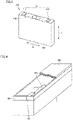
- Fig. 1 is a diagram showing a basic configuration of a battery pack 1.
- Fig. 2 is a diagram showing battery cells 100 and end plates 200 included in battery pack 1.
- battery pack 1 which serves as an exemplary “power storage module” includes battery cells 100, end plates 200, and a restraint member 300.
- the plurality of battery cells 100 are provided side by side in a Y axis direction (arrangement direction). Thus, a stack of battery cells 100 is formed. A separator (not shown) is interposed between the plurality of battery cells 100. The plurality of battery cells 100, which are sandwiched between two end plates 200, are pressed by end plates 200, and are therefore restrained between two end plates 200.
- End plates 200 are disposed beside both ends of battery pack 1 in the Y axis direction. Each of end plates 200 is fixed to a base such as a case that accommodates battery pack 1. Stepped portions 210 are formed at both ends of end plate 200 in an X axis direction (width direction).
- Restraint member 300 connects two end plates 200 to each other. Restraint member 300 is attached to stepped portions 210 formed on two end plates 200.
- Restraint member 300 is engaged with end plates 200 with compression force in the Y axis direction being exerted to the stack of the plurality of battery cells 100 and end plates 200, and then the compression force is released, with the result that tensile force acts on restraint member 300 that connects two end plates 200 to each other. As a reaction thereto, restraint member 300 presses two end plates 200 in directions of bringing them closer to each other.
- Restraint member 300 includes a first member 310 and a second member 320.
- First member 310 and second member 320 are coupled to each other by butt welding, for example.
- Tip surfaces formed by folding second member 320 are brought into abutment with stepped portions 210 of end plate 200 in the Y axis direction.
- Fig. 3 is a diagram showing battery cell 100 in battery pack 1. As shown in Fig. 3 , battery cell 100 includes an electrode terminal 110, a housing 120, and a gas discharge valve 130.
- Electrode terminal 110 includes a positive electrode terminal 111 and a negative electrode terminal 112. Electrode terminal 110 is formed on housing 120. Housing 120 is formed to have a substantially rectangular parallelepiped shape. An electrode assembly (not shown) and an electrolyte solution (not shown) are accommodated in housing 120. Gas discharge valve 130 is fractured when pressure inside housing 120 becomes equal to or more than a predetermined value. Thus, gas in housing 120 is discharged to the outside of housing 120.
- Fig. 4 is a perspective view showing a state in which a wiring module is provided on battery pack 1.
- a plate member 400 is placed on battery pack 1, and a flexible printed circuit board 500 is provided on plate member 400.
- Flexible printed circuit board 500 can be electrically connected to an external device via a connector 600.
- a cover member 700 is provided on plate member 400 so as to cover flexible printed circuit board 500.
- Fig. 5 is a schematic top view of the wiring module placed on battery pack 1. As shown in Fig. 5 , the wiring module includes plate member 400, flexible printed circuit board 500, and connector 600.
- Plate member 400 (bus bar plate) is a resin plate having insulation property and heat resistance.
- Plate member 400 has: a bottom surface portion 400A extending in each of the X axis direction and the Y axis direction; and a side surface portion 400B formed to extend upward from bottom surface portion 400A in a Z axis direction.
- Plate member 400 is provided with a wall portion 410, and openings 420, 430.
- Wall portion 410 is formed to extend upward from bottom surface portion 400A of plate member 400 in the Z axis direction.
- Wall portion 410 includes: a first wall portion 411 formed on the center side in the X axis direction; and a second wall portion 412 provided on the outer side in the X axis direction in parallel with first wall portion 411.
- Each of first wall portion 411 and second wall portion 412 is formed to extend discontinuously in the Y axis direction.
- first wall portion 411 and second wall portion 412 can serve as a protection wall that prevents sparking generated in plate member 400 from being directly exposed to outside while securing a path for discharging, to the outside of the battery pack, the gas discharged from housing 120 of battery cell 100.
- Each of openings 420 is located above gas discharge valve 130 of battery cell 100.
- Each of openings 430 is located above electrode terminal 110 of battery cell 100.
- Flexible printed circuit board 500 is placed on bottom surface portion 400A of plate member 400.
- Flexible printed circuit board 500 is a board in which an electric circuit is formed on a base member including a base film having an insulation property and a conductive metal foil.
- the base film is composed of, for example, polyimide or the like.
- the conductive metal foil is composed of, for example, a copper foil or the like.
- Flexible printed circuit board 500 has flexibility and has such a characteristic that the electric characteristics of flexible printed circuit board 500 are maintained even when deformed.
- connection terminal 530 electrically connected to electrode terminal 110 is provided on flexible printed circuit board 500.
- Connection terminal 530 is joined to a bus bar 100A that couples electrode terminals 110 of the plurality of battery cells 100.
- the electric circuit provided on flexible printed circuit board 500 and battery pack 1 are electrically connected to each other.
- Connector 600 is fixed to flexible printed circuit board 500.
- the electric circuit in flexible printed circuit board 500 and an external electric device can be electrically connected to each other via connector 600.
- Fig. 6 is an enlarged partial top view showing surroundings of a connection piece portion of the flexible printed circuit board and the connection terminal.
- flexible printed circuit board 500 includes a main body portion 510 and a connection piece portion 520.
- Connection piece portion 520 extends from main body portion 510 and is curved to have a substantially U-shape. Specifically, connection piece portion 520 extends from an end edge of main body portion 510 in the X axis direction. However, connection piece portion 520 may extend from an end edge of main body portion 510 in the Y axis direction. Connection piece portion 520 includes: a first straight portion 521 extending straightly in the Y axis direction; and a second straight portion 522 extending in parallel with first straight portion 521 with a gap being interposed between second straight portion 522 and first straight portion 521. Each of first straight portion 521 and second straight portion 522 has a certain width and extends straightly.
- First straight portion 521 and second straight portion 522 are connected to each other by a semi-arc portion 523.
- first straight portion 521 is located on the main body portion side with respect to second straight portion 522.
- First straight portion 521 extends in parallel with main body portion 510 with a gap being interposed between first straight portion 521 and main body portion 510.
- An outer edge 524 of a root portion of connection piece portion 520 extends to have an obtuse interior angle with respect to a portion of an end edge of main body portion 510, and is connected to the portion of the end edge.
- An inner edge 525 of the root portion of connection piece portion 520 has a semi-arc shape, and is connected to another portion of the end edge of main body portion 510.
- Connection terminal 530 is connected to the tip of connection piece portion 520.
- the tip portion of connection piece portion 520 connected to connection terminal 530 is not included in the straight portion.
- Length L2 of second straight portion 522 is longer than length L1 of first straight portion 521.
- a space 550 is formed by first straight portion 521 being shorter than second straight portion 522.
- connection terminal 530 is located in space 550. Since first straight portion 521 is thus shorter than second straight portion 522, the occupied area of connection piece portion 520 can be made small, thereby attaining an efficient layout. It should be noted that the efficient layout may be attained by disposing another member in space 550.
- first straight portion 521 has the same length as that of second straight portion 522, no space 550 is formed. In this case, a space for disposing a portion of connection terminal 530 therein is additionally required, with the result that the layout cannot be efficient.
- connection terminal 530 Displacements (in the X axis direction, the Y axis direction, and the Z axis direction) of connection terminal 530 can be absorbed by connection piece portion 520.
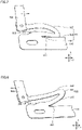
- Fig. 7 is a partial top view showing a deformed state of the connection piece portion when the connection terminal is displaced to one side in the Y axis direction.
- Fig. 8 is a partial top view showing a deformed state of the connection piece portion when the connection terminal is displaced to the other side in the Y axis direction.
- connection terminal 530 when connection terminal 530 is displaced to one side in the Y axis direction, second straight portion 522 is bent more greatly than first straight portion 521.
- first straight portion 521 is bent more greatly than second straight portion 522.
- Respective positions of the bent portions of first straight portion 521 and second straight portion 522 when connection terminal 530 is displaced to one side in the Y axis direction are different from respective positions of the bent portions of first straight portion 521 and second straight portion 522 when connection terminal 530 is displaced to the other side in the Y axis direction.
- Fig. 9 is an enlarged partial top view showing surroundings of a connection piece portion of a flexible printed circuit board and a connection terminal according to a modification.
- second straight portion 522 is located on the main body portion side with respect to first straight portion 521.
- first straight portion 521 is shorter than second straight portion 522, stress is generated at distributed positions in the event of vibration of connection piece portion 520, thereby attaining a long fatigue life against the stress generated in the event of vibration of connection piece portion 520.
- the tip of semi-arc portion 523 is located at a position on the inner side with respect to the tip of electrode terminal 110 in the Y axis direction as compared with the embodiment shown in Fig. 6 , a member or the like with regard to the power storage module can be also disposed in a space 551 resulting from this positional relation.
- flexible printed circuit board 500 has: main body portion 510; and connection piece portion 520 that extends from main body portion 510 and is curved so as to be connected to connection terminal 530.
- Connection piece portion 520 includes: first straight portion 521 straightly extending in the stacking direction of battery cells 100; and second straight portion 522 extending in parallel with first straight portion 521 with a gap being interposed between second straight portion 522 and first straight portion 521. Second straight portion 522 is longer than first straight portion 521.
- the occupied area of connection piece portion 520 can be made small while securing a required fatigue life against stress generated in the event of vibration in connection piece portion 520, thereby attaining an efficient layout.
- first straight portion 521 and second straight portion 522 are connected to each other by semi-arc portion 523.
- stress generated in semi-arc portion 523 in the event of bending of connection piece portion 520 can be distributed. This results in a long fatigue life against the stress generated in the event of vibration of connection piece portion 520.
- outer edge 524 of the root portion of connection piece portion 520 extends to have an obtuse interior angle with respect to the edge of main body portion 510, and inner edge 525 of the root portion of connection piece portion 520 has a semi-arc shape.
Abstract
A flexible printed circuit board (500) is placed on a bottom surface portion and has an electric circuit electrically connected to a plurality of power storage cells. A connection terminal (530) is provided on the flexible printed circuit board (500) and is electrically connected to an electrode terminal (110). The flexible printed circuit board (500) has a main body portion (510), and a connection piece portion (520) that extends from the main body portion (510) and is curved so as to be connected to the connection terminal (530). The connection piece portion (520) includes a first straight portion (521) extending straightly in a stacking direction of the power storage cells, and a second straight portion (522) extending in parallel with the first straight portion (521) with a gap being interposed between second straight portion (522) and the first straight portion (521). The second straight portion (522) is longer than the first straight portion (521).
Description
- This nonprovisional application is based on
Japanese Patent Application No. 2020-211173 filed on December 21, 2020 - The present technology relates to a power storage module.
-
Japanese Utility Model Laying-Open No. 58-153468 Japanese Utility Model Laying-Open No. 58-153468 - An efficient layout is required for the connection piece portion of the flexible printed circuit board to attain a small occupied area while securing a required fatigue life against stress generated in the event of vibration. Since the connection piece portion of the flexible printed circuit board described in
Japanese Utility Model Laying-Open No. 58-153468 - An object of the present technology is to provide a power storage module in which an efficient layout can be attained in a connection piece portion of a flexible printed circuit board by attaining a small occupied area while securing a required fatigue life against stress generated in the event of vibration.
- A power storage module according to the present technology includes a stack, a resin plate, a flexible printed circuit board, and a connection terminal. In the stack, a plurality of power storage cells each including an electrode terminal are stacked in a stacking direction. The resin plate has a bottom surface portion extending in each of the stacking direction and a width direction orthogonal to the stacking direction, and is placed on the stack. The flexible printed circuit board is placed on the bottom portion, and has an electric circuit electrically connected to the plurality of power storage cells. The connection terminal is provided on the flexible printed circuit board and is electrically connected to the electrode terminal. The flexible printed circuit board has a main body portion, and a connection piece portion that extends from the main body portion and is curved so as to be connected to the connection terminal. The connection piece portion includes a first straight portion extending straightly in the stacking direction, and a second straight portion extending in parallel with the first straight portion with a gap being interposed between the second straight portion and the first straight portion. The second straight portion is longer than the first straight portion.
- The foregoing and other objects, features, aspects and advantages of the present invention will become more apparent from the following detailed description of the present invention when taken in conjunction with the accompanying drawings.
-
-
Fig. 1 is a diagram showing a basic configuration of a battery pack. -
Fig. 2 is a diagram showing battery cells and end plates in the battery pack shown inFig. 1 . -
Fig. 3 is a diagram showing a battery cell in the battery pack shown inFig. 1 . -
Fig. 4 is a perspective view showing a state in which a wiring module is provided on the battery pack. -
Fig. 5 is a schematic top view of the wiring module placed on the battery pack. -
Fig. 6 is an enlarged partial top view showing surroundings of a connection piece portion of a flexible printed circuit board and a connection terminal. -
Fig. 7 is a partial top view showing a deformed state of the connection piece portion when the connection terminal is displaced to one side in a Y axis direction. -
Fig. 8 is a partial top view showing a deformed state of the connection piece portion when the connection terminal is displaced to the other side in the Y axis direction. -
Fig. 9 is an enlarged partial top view showing surroundings of a connection piece portion of a flexible printed circuit board and a connection terminal according to a modification. - Hereinafter, embodiments of the present technology will be described. It should be noted that the same or corresponding portions are denoted by the same reference characters, and may not be described repeatedly.
- It should be noted that in the embodiments described below, when reference is made to number, amount, and the like, the scope of the present technology is not necessarily limited to the number, amount, and the like unless otherwise stated particularly. Further, in the embodiments described below, each component is not necessarily essential to the present technology unless otherwise stated particularly.
- It should be noted that in the present specification, the terms "comprise", "include", and "have" are open-end terms. That is, when a certain configuration is included, a configuration other than the foregoing configuration may or may not be included. Further, the present technology is not limited to one that necessarily exhibits all the functions and effects stated in the present embodiment.
- In the present specification, the term "battery" is not limited to a lithium ion battery, and may include another battery such as a nickel-metal hydride battery. In the present specification, the term "electrode" may collectively represent a positive electrode and a negative electrode. Further, the term "electrode plate" may collectively represent a positive electrode plate and a negative electrode plate.
- In the present specification, the "power storage cell" or the "power storage module" is not limited to a battery cell or a battery module, and may include a capacitor cell or a capacitor module.
-
Fig. 1 is a diagram showing a basic configuration of a battery pack 1.Fig. 2 is a diagram showingbattery cells 100 andend plates 200 included in battery pack 1. - As shown in
Figs. 1 and 2 , battery pack 1, which serves as an exemplary "power storage module", includesbattery cells 100,end plates 200, and arestraint member 300. - The plurality of
battery cells 100 are provided side by side in a Y axis direction (arrangement direction). Thus, a stack ofbattery cells 100 is formed. A separator (not shown) is interposed between the plurality ofbattery cells 100. The plurality ofbattery cells 100, which are sandwiched between twoend plates 200, are pressed byend plates 200, and are therefore restrained between twoend plates 200. -
End plates 200 are disposed beside both ends of battery pack 1 in the Y axis direction. Each ofend plates 200 is fixed to a base such as a case that accommodates battery pack 1. Steppedportions 210 are formed at both ends ofend plate 200 in an X axis direction (width direction). - Restraint
member 300 connects twoend plates 200 to each other. Restraintmember 300 is attached to steppedportions 210 formed on twoend plates 200. - Restraint
member 300 is engaged withend plates 200 with compression force in the Y axis direction being exerted to the stack of the plurality ofbattery cells 100 andend plates 200, and then the compression force is released, with the result that tensile force acts onrestraint member 300 that connects twoend plates 200 to each other. As a reaction thereto,restraint member 300 presses twoend plates 200 in directions of bringing them closer to each other. -
Restraint member 300 includes afirst member 310 and asecond member 320.First member 310 andsecond member 320 are coupled to each other by butt welding, for example. Tip surfaces formed by foldingsecond member 320 are brought into abutment withstepped portions 210 ofend plate 200 in the Y axis direction. -
Fig. 3 is a diagram showingbattery cell 100 in battery pack 1. As shown inFig. 3 ,battery cell 100 includes anelectrode terminal 110, ahousing 120, and agas discharge valve 130. -
Electrode terminal 110 includes apositive electrode terminal 111 and anegative electrode terminal 112.Electrode terminal 110 is formed onhousing 120.Housing 120 is formed to have a substantially rectangular parallelepiped shape. An electrode assembly (not shown) and an electrolyte solution (not shown) are accommodated inhousing 120.Gas discharge valve 130 is fractured when pressure insidehousing 120 becomes equal to or more than a predetermined value. Thus, gas inhousing 120 is discharged to the outside ofhousing 120. -
Fig. 4 is a perspective view showing a state in which a wiring module is provided on battery pack 1. As shown inFig. 4 , aplate member 400 is placed on battery pack 1, and a flexible printedcircuit board 500 is provided onplate member 400. Flexible printedcircuit board 500 can be electrically connected to an external device via aconnector 600. Acover member 700 is provided onplate member 400 so as to cover flexible printedcircuit board 500. -
Fig. 5 is a schematic top view of the wiring module placed on battery pack 1. As shown inFig. 5 , the wiring module includesplate member 400, flexible printedcircuit board 500, andconnector 600. - Plate member 400 (bus bar plate) is a resin plate having insulation property and heat resistance.
Plate member 400 has: abottom surface portion 400A extending in each of the X axis direction and the Y axis direction; and aside surface portion 400B formed to extend upward frombottom surface portion 400A in a Z axis direction.Plate member 400 is provided with awall portion 410, andopenings -
Wall portion 410 is formed to extend upward frombottom surface portion 400A ofplate member 400 in the Z axis direction.Wall portion 410 includes: afirst wall portion 411 formed on the center side in the X axis direction; and asecond wall portion 412 provided on the outer side in the X axis direction in parallel withfirst wall portion 411. Each offirst wall portion 411 andsecond wall portion 412 is formed to extend discontinuously in the Y axis direction. - Each of
first wall portion 411 andsecond wall portion 412 can serve as a protection wall that prevents sparking generated inplate member 400 from being directly exposed to outside while securing a path for discharging, to the outside of the battery pack, the gas discharged fromhousing 120 ofbattery cell 100. - Each of
openings 420 is located abovegas discharge valve 130 ofbattery cell 100. Each ofopenings 430 is located aboveelectrode terminal 110 ofbattery cell 100. - Flexible printed
circuit board 500 is placed onbottom surface portion 400A ofplate member 400. Flexible printedcircuit board 500 is a board in which an electric circuit is formed on a base member including a base film having an insulation property and a conductive metal foil. The base film is composed of, for example, polyimide or the like. The conductive metal foil is composed of, for example, a copper foil or the like. Flexible printedcircuit board 500 has flexibility and has such a characteristic that the electric characteristics of flexible printedcircuit board 500 are maintained even when deformed. - A
connection terminal 530 electrically connected to electrode terminal 110 is provided on flexible printedcircuit board 500.Connection terminal 530 is joined to abus bar 100A that coupleselectrode terminals 110 of the plurality ofbattery cells 100. Thus, the electric circuit provided on flexible printedcircuit board 500 and battery pack 1 are electrically connected to each other. -
Connector 600 is fixed to flexible printedcircuit board 500. The electric circuit in flexible printedcircuit board 500 and an external electric device can be electrically connected to each other viaconnector 600. -
Fig. 6 is an enlarged partial top view showing surroundings of a connection piece portion of the flexible printed circuit board and the connection terminal. As shown inFigs. 5 and 6 , flexible printedcircuit board 500 includes amain body portion 510 and aconnection piece portion 520. -
Connection piece portion 520 extends frommain body portion 510 and is curved to have a substantially U-shape. Specifically,connection piece portion 520 extends from an end edge ofmain body portion 510 in the X axis direction. However,connection piece portion 520 may extend from an end edge ofmain body portion 510 in the Y axis direction.Connection piece portion 520 includes: a firststraight portion 521 extending straightly in the Y axis direction; and a secondstraight portion 522 extending in parallel with firststraight portion 521 with a gap being interposed between secondstraight portion 522 and firststraight portion 521. Each of firststraight portion 521 and secondstraight portion 522 has a certain width and extends straightly. Firststraight portion 521 and secondstraight portion 522 are connected to each other by asemi-arc portion 523. In the present embodiment, firststraight portion 521 is located on the main body portion side with respect to secondstraight portion 522. Firststraight portion 521 extends in parallel withmain body portion 510 with a gap being interposed between firststraight portion 521 andmain body portion 510. - An
outer edge 524 of a root portion ofconnection piece portion 520 extends to have an obtuse interior angle with respect to a portion of an end edge ofmain body portion 510, and is connected to the portion of the end edge. Aninner edge 525 of the root portion ofconnection piece portion 520 has a semi-arc shape, and is connected to another portion of the end edge ofmain body portion 510.Connection terminal 530 is connected to the tip ofconnection piece portion 520. The tip portion ofconnection piece portion 520 connected toconnection terminal 530 is not included in the straight portion. Length L2 of secondstraight portion 522 is longer than length L1 of firststraight portion 521. Aspace 550 is formed by firststraight portion 521 being shorter than secondstraight portion 522. A portion ofconnection terminal 530 is located inspace 550. Since firststraight portion 521 is thus shorter than secondstraight portion 522, the occupied area ofconnection piece portion 520 can be made small, thereby attaining an efficient layout. It should be noted that the efficient layout may be attained by disposing another member inspace 550. - If first
straight portion 521 has the same length as that of secondstraight portion 522, nospace 550 is formed. In this case, a space for disposing a portion ofconnection terminal 530 therein is additionally required, with the result that the layout cannot be efficient. - Displacements (in the X axis direction, the Y axis direction, and the Z axis direction) of
connection terminal 530 can be absorbed byconnection piece portion 520.Fig. 7 is a partial top view showing a deformed state of the connection piece portion when the connection terminal is displaced to one side in the Y axis direction.Fig. 8 is a partial top view showing a deformed state of the connection piece portion when the connection terminal is displaced to the other side in the Y axis direction. - As shown in
Fig. 7 , whenconnection terminal 530 is displaced to one side in the Y axis direction, secondstraight portion 522 is bent more greatly than firststraight portion 521. As shown inFig. 8 , whenconnection terminal 530 is displaced to the other side in the Y axis direction, firststraight portion 521 is bent more greatly than secondstraight portion 522. Respective positions of the bent portions of firststraight portion 521 and secondstraight portion 522 whenconnection terminal 530 is displaced to one side in the Y axis direction are different from respective positions of the bent portions of firststraight portion 521 and secondstraight portion 522 whenconnection terminal 530 is displaced to the other side in the Y axis direction. Thus, stress is generated at the distributed positions in the event of vibration ofconnection piece portion 520, thereby attaining a long fatigue life against the stress generated in the event of vibration ofconnection piece portion 520. -
Fig. 9 is an enlarged partial top view showing surroundings of a connection piece portion of a flexible printed circuit board and a connection terminal according to a modification. As shown inFig. 9 , in the modification, secondstraight portion 522 is located on the main body portion side with respect to firststraight portion 521. Also in this case, since firststraight portion 521 is shorter than secondstraight portion 522, stress is generated at distributed positions in the event of vibration ofconnection piece portion 520, thereby attaining a long fatigue life against the stress generated in the event of vibration ofconnection piece portion 520. Further, since the tip ofsemi-arc portion 523 is located at a position on the inner side with respect to the tip ofelectrode terminal 110 in the Y axis direction as compared with the embodiment shown inFig. 6 , a member or the like with regard to the power storage module can be also disposed in aspace 551 resulting from this positional relation. - In the power storage module according to the present embodiment, flexible printed
circuit board 500 has:main body portion 510; andconnection piece portion 520 that extends frommain body portion 510 and is curved so as to be connected toconnection terminal 530.Connection piece portion 520 includes: firststraight portion 521 straightly extending in the stacking direction ofbattery cells 100; and secondstraight portion 522 extending in parallel with firststraight portion 521 with a gap being interposed between secondstraight portion 522 and firststraight portion 521. Secondstraight portion 522 is longer than firststraight portion 521. Thus, the occupied area ofconnection piece portion 520 can be made small while securing a required fatigue life against stress generated in the event of vibration inconnection piece portion 520, thereby attaining an efficient layout. - In the power storage module according to the present embodiment, first
straight portion 521 and secondstraight portion 522 are connected to each other bysemi-arc portion 523. Thus, stress generated insemi-arc portion 523 in the event of bending ofconnection piece portion 520 can be distributed. This results in a long fatigue life against the stress generated in the event of vibration ofconnection piece portion 520. - In the power storage module according to the present embodiment,
outer edge 524 of the root portion ofconnection piece portion 520 extends to have an obtuse interior angle with respect to the edge ofmain body portion 510, andinner edge 525 of the root portion ofconnection piece portion 520 has a semi-arc shape. Thus, stress generated at the root portion ofconnection piece portion 520 in the event of bending ofconnection piece portion 520 can be distributed. This results in a long fatigue life against the stress generated in the event of vibration ofconnection piece portion 520. - Although the embodiments of the present invention have been described and illustrated in detail, it is clearly understood that the same is by way of illustration and example only and is not to be taken by way of limitation, the scope of the present invention being interpreted by the terms of the appended claims.
Claims (5)
- A power storage module comprising:a stack in which a plurality of power storage cells (100) each including an electrode terminal (110) are stacked in a stacking direction;a resin plate (400) having a bottom surface portion (400A) extending in each of the stacking direction and a width direction orthogonal to the stacking direction, the resin plate (400) being placed on the stack;a flexible printed circuit board (500) placed on the bottom surface portion (400A) and having an electric circuit electrically connected to the plurality of power storage cells (100); anda connection terminal (530) provided on the flexible printed circuit board (500) and electrically connected to the electrode terminal (110), whereinthe flexible printed circuit board (500) has a main body portion (510), and a connection piece portion (520) that extends from the main body portion (510) and is curved so as to be connected to the connection terminal (530),the connection piece portion (520) includes a first straight portion (521) extending straightly in the stacking direction, and a second straight portion (522) extending in parallel with the first straight portion (521) with a gap being interposed between the second straight portion (522) and the first straight portion (521), andthe second straight portion (522) is longer than the first straight portion (521).
- The power storage module according to claim 1, wherein the first straight portion (521) and the second straight portion (522) are connected to each other by a semi-arc portion (523).
- The power storage module according to claim 1 or 2, wherein the first straight portion (521) is located on the main body portion (510) side with respect to the second straight portion (522).
- The power storage module according to claim 1 or 2, wherein the second straight portion (522) is located on the main body portion (510) side with respect to the first straight portion (521).
- The power storage module according to any one of claims 1 to 3, wherein a portion of the connection terminal (530) is located in a space (550) formed by the first straight portion (521) being shorter than the second straight portion (522).
Applications Claiming Priority (1)
| Application Number | Priority Date | Filing Date | Title |
|---|---|---|---|
| JP2020211173A JP7253525B2 (en) | 2020-12-21 | 2020-12-21 | storage module |
Publications (1)
| Publication Number | Publication Date |
|---|---|
| EP4016722A1 true EP4016722A1 (en) | 2022-06-22 |
Family
ID=78725326
Family Applications (1)
| Application Number | Title | Priority Date | Filing Date |
|---|---|---|---|
| EP21209566.5A Pending EP4016722A1 (en) | 2020-12-21 | 2021-11-22 | Power storage module |
Country Status (5)
| Country | Link |
|---|---|
| US (1) | US20220200088A1 (en) |
| EP (1) | EP4016722A1 (en) |
| JP (1) | JP7253525B2 (en) |
| KR (1) | KR20220089648A (en) |
| CN (1) | CN114649644B (en) |
Citations (5)
| Publication number | Priority date | Publication date | Assignee | Title |
|---|---|---|---|---|
| JPS58153468U (en) | 1982-04-08 | 1983-10-14 | 株式会社フジクラ | flexible printed circuit board |
| WO2018117567A1 (en) * | 2016-12-23 | 2018-06-28 | Samsung Electronics Co., Ltd. | Protective circuit module case of battery and electronic device including the same |
| US20190181418A1 (en) * | 2017-12-11 | 2019-06-13 | Samsung Sdi Co., Ltd. | Battery pack |
| EP3731308A1 (en) * | 2018-01-22 | 2020-10-28 | Contemporary Amperex Technology Co., Limited | Battery pack |
| US20200396830A1 (en) * | 2019-06-17 | 2020-12-17 | Yazaki Corporation | Busbar Module |
Family Cites Families (6)
| Publication number | Priority date | Publication date | Assignee | Title |
|---|---|---|---|---|
| JP5702947B2 (en) * | 2010-04-22 | 2015-04-15 | 矢崎総業株式会社 | Wiring material |
| JP2012190678A (en) * | 2011-03-11 | 2012-10-04 | Kojima Press Industry Co Ltd | Bus bar module for power storage unit |
| JP6136697B2 (en) * | 2013-07-22 | 2017-05-31 | 株式会社デンソー | Assembled battery |
| JP6164489B2 (en) * | 2014-01-21 | 2017-07-19 | 株式会社オートネットワーク技術研究所 | Wiring module |
| JP6691178B2 (en) * | 2018-07-10 | 2020-04-28 | 矢崎総業株式会社 | Protector and bus bar module |
| JP7212504B2 (en) * | 2018-11-22 | 2023-01-25 | 株式会社オートネットワーク技術研究所 | connection module |
-
2020
- 2020-12-21 JP JP2020211173A patent/JP7253525B2/en active Active
-
2021
- 2021-11-22 EP EP21209566.5A patent/EP4016722A1/en active Pending
- 2021-12-14 KR KR1020210178630A patent/KR20220089648A/en not_active Application Discontinuation
- 2021-12-15 US US17/551,426 patent/US20220200088A1/en active Pending
- 2021-12-20 CN CN202111585545.XA patent/CN114649644B/en active Active
Patent Citations (5)
| Publication number | Priority date | Publication date | Assignee | Title |
|---|---|---|---|---|
| JPS58153468U (en) | 1982-04-08 | 1983-10-14 | 株式会社フジクラ | flexible printed circuit board |
| WO2018117567A1 (en) * | 2016-12-23 | 2018-06-28 | Samsung Electronics Co., Ltd. | Protective circuit module case of battery and electronic device including the same |
| US20190181418A1 (en) * | 2017-12-11 | 2019-06-13 | Samsung Sdi Co., Ltd. | Battery pack |
| EP3731308A1 (en) * | 2018-01-22 | 2020-10-28 | Contemporary Amperex Technology Co., Limited | Battery pack |
| US20200396830A1 (en) * | 2019-06-17 | 2020-12-17 | Yazaki Corporation | Busbar Module |
Also Published As
| Publication number | Publication date |
|---|---|
| CN114649644A (en) | 2022-06-21 |
| JP2022097917A (en) | 2022-07-01 |
| JP7253525B2 (en) | 2023-04-06 |
| CN114649644B (en) | 2024-01-02 |
| KR20220089648A (en) | 2022-06-28 |
| US20220200088A1 (en) | 2022-06-23 |
Similar Documents
| Publication | Publication Date | Title |
|---|---|---|
| CN114649648B (en) | Power storage module | |
| EP4016722A1 (en) | Power storage module | |
| EP4024586A1 (en) | Power storage module | |
| US20220200061A1 (en) | Power storage module | |
| US20220200065A1 (en) | Power storage module and method of manufacturing same | |
| US20220200062A1 (en) | Power storage module | |
| EP4016023A1 (en) | Power storage module | |
| EP4333157A1 (en) | Battery module | |
| US20220200090A1 (en) | Power storage module | |
| US20240079708A1 (en) | Battery module | |
| EP4333155A2 (en) | Battery module |
Legal Events
| Date | Code | Title | Description |
|---|---|---|---|
| PUAI | Public reference made under article 153(3) epc to a published international application that has entered the european phase |
Free format text: ORIGINAL CODE: 0009012 |
|
| STAA | Information on the status of an ep patent application or granted ep patent |
Free format text: STATUS: REQUEST FOR EXAMINATION WAS MADE |
|
| 17P | Request for examination filed |
Effective date: 20211122 |
|
| AK | Designated contracting states |
Kind code of ref document: A1 Designated state(s): AL AT BE BG CH CY CZ DE DK EE ES FI FR GB GR HR HU IE IS IT LI LT LU LV MC MK MT NL NO PL PT RO RS SE SI SK SM TR |
|
| RAP3 | Party data changed (applicant data changed or rights of an application transferred) |
Owner name: PRIME PLANET ENERGY & SOLUTIONS, INC. |