EP4016696A1 - System and method for ultrasonic inspection - Google Patents
System and method for ultrasonic inspection Download PDFInfo
- Publication number
- EP4016696A1 EP4016696A1 EP21808839.1A EP21808839A EP4016696A1 EP 4016696 A1 EP4016696 A1 EP 4016696A1 EP 21808839 A EP21808839 A EP 21808839A EP 4016696 A1 EP4016696 A1 EP 4016696A1
- Authority
- EP
- European Patent Office
- Prior art keywords
- thermally conductive
- conductive resin
- ultrasonic
- liquid
- module frame
- Prior art date
- Legal status (The legal status is an assumption and is not a legal conclusion. Google has not performed a legal analysis and makes no representation as to the accuracy of the status listed.)
- Pending
Links
Images




Classifications
-
- B—PERFORMING OPERATIONS; TRANSPORTING
- B29—WORKING OF PLASTICS; WORKING OF SUBSTANCES IN A PLASTIC STATE IN GENERAL
- B29C—SHAPING OR JOINING OF PLASTICS; SHAPING OF MATERIAL IN A PLASTIC STATE, NOT OTHERWISE PROVIDED FOR; AFTER-TREATMENT OF THE SHAPED PRODUCTS, e.g. REPAIRING
- B29C45/00—Injection moulding, i.e. forcing the required volume of moulding material through a nozzle into a closed mould; Apparatus therefor
- B29C45/14—Injection moulding, i.e. forcing the required volume of moulding material through a nozzle into a closed mould; Apparatus therefor incorporating preformed parts or layers, e.g. injection moulding around inserts or for coating articles
- B29C45/14467—Joining articles or parts of a single article
- B29C45/14508—Joining juxtaposed sheet-like articles, e.g. for making trim panels
-
- B—PERFORMING OPERATIONS; TRANSPORTING
- B29—WORKING OF PLASTICS; WORKING OF SUBSTANCES IN A PLASTIC STATE IN GENERAL
- B29C—SHAPING OR JOINING OF PLASTICS; SHAPING OF MATERIAL IN A PLASTIC STATE, NOT OTHERWISE PROVIDED FOR; AFTER-TREATMENT OF THE SHAPED PRODUCTS, e.g. REPAIRING
- B29C45/00—Injection moulding, i.e. forcing the required volume of moulding material through a nozzle into a closed mould; Apparatus therefor
- B29C45/17—Component parts, details or accessories; Auxiliary operations
- B29C45/76—Measuring, controlling or regulating
- B29C45/768—Detecting defective moulding conditions
-
- B—PERFORMING OPERATIONS; TRANSPORTING
- B29—WORKING OF PLASTICS; WORKING OF SUBSTANCES IN A PLASTIC STATE IN GENERAL
- B29C—SHAPING OR JOINING OF PLASTICS; SHAPING OF MATERIAL IN A PLASTIC STATE, NOT OTHERWISE PROVIDED FOR; AFTER-TREATMENT OF THE SHAPED PRODUCTS, e.g. REPAIRING
- B29C45/00—Injection moulding, i.e. forcing the required volume of moulding material through a nozzle into a closed mould; Apparatus therefor
- B29C45/14—Injection moulding, i.e. forcing the required volume of moulding material through a nozzle into a closed mould; Apparatus therefor incorporating preformed parts or layers, e.g. injection moulding around inserts or for coating articles
- B29C45/14639—Injection moulding, i.e. forcing the required volume of moulding material through a nozzle into a closed mould; Apparatus therefor incorporating preformed parts or layers, e.g. injection moulding around inserts or for coating articles for obtaining an insulating effect, e.g. for electrical components
-
- B—PERFORMING OPERATIONS; TRANSPORTING
- B29—WORKING OF PLASTICS; WORKING OF SUBSTANCES IN A PLASTIC STATE IN GENERAL
- B29C—SHAPING OR JOINING OF PLASTICS; SHAPING OF MATERIAL IN A PLASTIC STATE, NOT OTHERWISE PROVIDED FOR; AFTER-TREATMENT OF THE SHAPED PRODUCTS, e.g. REPAIRING
- B29C45/00—Injection moulding, i.e. forcing the required volume of moulding material through a nozzle into a closed mould; Apparatus therefor
- B29C45/14—Injection moulding, i.e. forcing the required volume of moulding material through a nozzle into a closed mould; Apparatus therefor incorporating preformed parts or layers, e.g. injection moulding around inserts or for coating articles
-
- B—PERFORMING OPERATIONS; TRANSPORTING
- B29—WORKING OF PLASTICS; WORKING OF SUBSTANCES IN A PLASTIC STATE IN GENERAL
- B29C—SHAPING OR JOINING OF PLASTICS; SHAPING OF MATERIAL IN A PLASTIC STATE, NOT OTHERWISE PROVIDED FOR; AFTER-TREATMENT OF THE SHAPED PRODUCTS, e.g. REPAIRING
- B29C45/00—Injection moulding, i.e. forcing the required volume of moulding material through a nozzle into a closed mould; Apparatus therefor
- B29C45/14—Injection moulding, i.e. forcing the required volume of moulding material through a nozzle into a closed mould; Apparatus therefor incorporating preformed parts or layers, e.g. injection moulding around inserts or for coating articles
- B29C45/14336—Coating a portion of the article, e.g. the edge of the article
-
- B—PERFORMING OPERATIONS; TRANSPORTING
- B29—WORKING OF PLASTICS; WORKING OF SUBSTANCES IN A PLASTIC STATE IN GENERAL
- B29C—SHAPING OR JOINING OF PLASTICS; SHAPING OF MATERIAL IN A PLASTIC STATE, NOT OTHERWISE PROVIDED FOR; AFTER-TREATMENT OF THE SHAPED PRODUCTS, e.g. REPAIRING
- B29C45/00—Injection moulding, i.e. forcing the required volume of moulding material through a nozzle into a closed mould; Apparatus therefor
- B29C45/14—Injection moulding, i.e. forcing the required volume of moulding material through a nozzle into a closed mould; Apparatus therefor incorporating preformed parts or layers, e.g. injection moulding around inserts or for coating articles
- B29C45/14336—Coating a portion of the article, e.g. the edge of the article
- B29C45/14344—Moulding in or through a hole in the article, e.g. outsert moulding
-
- G—PHYSICS
- G01—MEASURING; TESTING
- G01F—MEASURING VOLUME, VOLUME FLOW, MASS FLOW OR LIQUID LEVEL; METERING BY VOLUME
- G01F23/00—Indicating or measuring liquid level or level of fluent solid material, e.g. indicating in terms of volume or indicating by means of an alarm
- G01F23/22—Indicating or measuring liquid level or level of fluent solid material, e.g. indicating in terms of volume or indicating by means of an alarm by measuring physical variables, other than linear dimensions, pressure or weight, dependent on the level to be measured, e.g. by difference of heat transfer of steam or water
- G01F23/28—Indicating or measuring liquid level or level of fluent solid material, e.g. indicating in terms of volume or indicating by means of an alarm by measuring physical variables, other than linear dimensions, pressure or weight, dependent on the level to be measured, e.g. by difference of heat transfer of steam or water by measuring the variations of parameters of electromagnetic or acoustic waves applied directly to the liquid or fluent solid material
- G01F23/296—Acoustic waves
- G01F23/2965—Measuring attenuation of transmitted waves
-
- G—PHYSICS
- G01—MEASURING; TESTING
- G01N—INVESTIGATING OR ANALYSING MATERIALS BY DETERMINING THEIR CHEMICAL OR PHYSICAL PROPERTIES
- G01N29/00—Investigating or analysing materials by the use of ultrasonic, sonic or infrasonic waves; Visualisation of the interior of objects by transmitting ultrasonic or sonic waves through the object
- G01N29/02—Analysing fluids
- G01N29/032—Analysing fluids by measuring attenuation of acoustic waves
-
- G—PHYSICS
- G01—MEASURING; TESTING
- G01N—INVESTIGATING OR ANALYSING MATERIALS BY DETERMINING THEIR CHEMICAL OR PHYSICAL PROPERTIES
- G01N29/00—Investigating or analysing materials by the use of ultrasonic, sonic or infrasonic waves; Visualisation of the interior of objects by transmitting ultrasonic or sonic waves through the object
- G01N29/04—Analysing solids
-
- H—ELECTRICITY
- H01—ELECTRIC ELEMENTS
- H01M—PROCESSES OR MEANS, e.g. BATTERIES, FOR THE DIRECT CONVERSION OF CHEMICAL ENERGY INTO ELECTRICAL ENERGY
- H01M10/00—Secondary cells; Manufacture thereof
- H01M10/42—Methods or arrangements for servicing or maintenance of secondary cells or secondary half-cells
-
- H—ELECTRICITY
- H01—ELECTRIC ELEMENTS
- H01M—PROCESSES OR MEANS, e.g. BATTERIES, FOR THE DIRECT CONVERSION OF CHEMICAL ENERGY INTO ELECTRICAL ENERGY
- H01M10/00—Secondary cells; Manufacture thereof
- H01M10/42—Methods or arrangements for servicing or maintenance of secondary cells or secondary half-cells
- H01M10/4285—Testing apparatus
-
- H—ELECTRICITY
- H01—ELECTRIC ELEMENTS
- H01M—PROCESSES OR MEANS, e.g. BATTERIES, FOR THE DIRECT CONVERSION OF CHEMICAL ENERGY INTO ELECTRICAL ENERGY
- H01M10/00—Secondary cells; Manufacture thereof
- H01M10/42—Methods or arrangements for servicing or maintenance of secondary cells or secondary half-cells
- H01M10/48—Accumulators combined with arrangements for measuring, testing or indicating the condition of cells, e.g. the level or density of the electrolyte
-
- H—ELECTRICITY
- H01—ELECTRIC ELEMENTS
- H01M—PROCESSES OR MEANS, e.g. BATTERIES, FOR THE DIRECT CONVERSION OF CHEMICAL ENERGY INTO ELECTRICAL ENERGY
- H01M10/00—Secondary cells; Manufacture thereof
- H01M10/60—Heating or cooling; Temperature control
- H01M10/64—Heating or cooling; Temperature control characterised by the shape of the cells
- H01M10/647—Prismatic or flat cells, e.g. pouch cells
-
- H—ELECTRICITY
- H01—ELECTRIC ELEMENTS
- H01M—PROCESSES OR MEANS, e.g. BATTERIES, FOR THE DIRECT CONVERSION OF CHEMICAL ENERGY INTO ELECTRICAL ENERGY
- H01M10/00—Secondary cells; Manufacture thereof
- H01M10/60—Heating or cooling; Temperature control
- H01M10/65—Means for temperature control structurally associated with the cells
- H01M10/653—Means for temperature control structurally associated with the cells characterised by electrically insulating or thermally conductive materials
-
- H—ELECTRICITY
- H01—ELECTRIC ELEMENTS
- H01M—PROCESSES OR MEANS, e.g. BATTERIES, FOR THE DIRECT CONVERSION OF CHEMICAL ENERGY INTO ELECTRICAL ENERGY
- H01M50/00—Constructional details or processes of manufacture of the non-active parts of electrochemical cells other than fuel cells, e.g. hybrid cells
- H01M50/20—Mountings; Secondary casings or frames; Racks, modules or packs; Suspension devices; Shock absorbers; Transport or carrying devices; Holders
-
- H—ELECTRICITY
- H01—ELECTRIC ELEMENTS
- H01M—PROCESSES OR MEANS, e.g. BATTERIES, FOR THE DIRECT CONVERSION OF CHEMICAL ENERGY INTO ELECTRICAL ENERGY
- H01M50/00—Constructional details or processes of manufacture of the non-active parts of electrochemical cells other than fuel cells, e.g. hybrid cells
- H01M50/20—Mountings; Secondary casings or frames; Racks, modules or packs; Suspension devices; Shock absorbers; Transport or carrying devices; Holders
- H01M50/204—Racks, modules or packs for multiple batteries or multiple cells
- H01M50/207—Racks, modules or packs for multiple batteries or multiple cells characterised by their shape
- H01M50/211—Racks, modules or packs for multiple batteries or multiple cells characterised by their shape adapted for pouch cells
-
- H—ELECTRICITY
- H01—ELECTRIC ELEMENTS
- H01M—PROCESSES OR MEANS, e.g. BATTERIES, FOR THE DIRECT CONVERSION OF CHEMICAL ENERGY INTO ELECTRICAL ENERGY
- H01M50/00—Constructional details or processes of manufacture of the non-active parts of electrochemical cells other than fuel cells, e.g. hybrid cells
- H01M50/20—Mountings; Secondary casings or frames; Racks, modules or packs; Suspension devices; Shock absorbers; Transport or carrying devices; Holders
- H01M50/218—Mountings; Secondary casings or frames; Racks, modules or packs; Suspension devices; Shock absorbers; Transport or carrying devices; Holders characterised by the material
- H01M50/22—Mountings; Secondary casings or frames; Racks, modules or packs; Suspension devices; Shock absorbers; Transport or carrying devices; Holders characterised by the material of the casings or racks
- H01M50/227—Organic material
-
- H—ELECTRICITY
- H01—ELECTRIC ELEMENTS
- H01M—PROCESSES OR MEANS, e.g. BATTERIES, FOR THE DIRECT CONVERSION OF CHEMICAL ENERGY INTO ELECTRICAL ENERGY
- H01M50/00—Constructional details or processes of manufacture of the non-active parts of electrochemical cells other than fuel cells, e.g. hybrid cells
- H01M50/60—Arrangements or processes for filling or topping-up with liquids; Arrangements or processes for draining liquids from casings
- H01M50/609—Arrangements or processes for filling with liquid, e.g. electrolytes
-
- B—PERFORMING OPERATIONS; TRANSPORTING
- B29—WORKING OF PLASTICS; WORKING OF SUBSTANCES IN A PLASTIC STATE IN GENERAL
- B29C—SHAPING OR JOINING OF PLASTICS; SHAPING OF MATERIAL IN A PLASTIC STATE, NOT OTHERWISE PROVIDED FOR; AFTER-TREATMENT OF THE SHAPED PRODUCTS, e.g. REPAIRING
- B29C2945/00—Indexing scheme relating to injection moulding, i.e. forcing the required volume of moulding material through a nozzle into a closed mould
- B29C2945/76—Measuring, controlling or regulating
- B29C2945/76003—Measured parameter
- B29C2945/76163—Errors, malfunctioning
-
- B—PERFORMING OPERATIONS; TRANSPORTING
- B29—WORKING OF PLASTICS; WORKING OF SUBSTANCES IN A PLASTIC STATE IN GENERAL
- B29C—SHAPING OR JOINING OF PLASTICS; SHAPING OF MATERIAL IN A PLASTIC STATE, NOT OTHERWISE PROVIDED FOR; AFTER-TREATMENT OF THE SHAPED PRODUCTS, e.g. REPAIRING
- B29C2945/00—Indexing scheme relating to injection moulding, i.e. forcing the required volume of moulding material through a nozzle into a closed mould
- B29C2945/76—Measuring, controlling or regulating
- B29C2945/76177—Location of measurement
- B29C2945/7629—Moulded articles
-
- B—PERFORMING OPERATIONS; TRANSPORTING
- B29—WORKING OF PLASTICS; WORKING OF SUBSTANCES IN A PLASTIC STATE IN GENERAL
- B29C—SHAPING OR JOINING OF PLASTICS; SHAPING OF MATERIAL IN A PLASTIC STATE, NOT OTHERWISE PROVIDED FOR; AFTER-TREATMENT OF THE SHAPED PRODUCTS, e.g. REPAIRING
- B29C2945/00—Indexing scheme relating to injection moulding, i.e. forcing the required volume of moulding material through a nozzle into a closed mould
- B29C2945/76—Measuring, controlling or regulating
- B29C2945/76451—Measurement means
- B29C2945/76474—Ultrasonic
-
- B—PERFORMING OPERATIONS; TRANSPORTING
- B29—WORKING OF PLASTICS; WORKING OF SUBSTANCES IN A PLASTIC STATE IN GENERAL
- B29C—SHAPING OR JOINING OF PLASTICS; SHAPING OF MATERIAL IN A PLASTIC STATE, NOT OTHERWISE PROVIDED FOR; AFTER-TREATMENT OF THE SHAPED PRODUCTS, e.g. REPAIRING
- B29C2945/00—Indexing scheme relating to injection moulding, i.e. forcing the required volume of moulding material through a nozzle into a closed mould
- B29C2945/76—Measuring, controlling or regulating
- B29C2945/76494—Controlled parameter
- B29C2945/76551—Time
- B29C2945/76558—Time termination
-
- B—PERFORMING OPERATIONS; TRANSPORTING
- B29—WORKING OF PLASTICS; WORKING OF SUBSTANCES IN A PLASTIC STATE IN GENERAL
- B29C—SHAPING OR JOINING OF PLASTICS; SHAPING OF MATERIAL IN A PLASTIC STATE, NOT OTHERWISE PROVIDED FOR; AFTER-TREATMENT OF THE SHAPED PRODUCTS, e.g. REPAIRING
- B29C2945/00—Indexing scheme relating to injection moulding, i.e. forcing the required volume of moulding material through a nozzle into a closed mould
- B29C2945/76—Measuring, controlling or regulating
- B29C2945/76822—Phase or stage of control
- B29C2945/76859—Injection
-
- B—PERFORMING OPERATIONS; TRANSPORTING
- B29—WORKING OF PLASTICS; WORKING OF SUBSTANCES IN A PLASTIC STATE IN GENERAL
- B29C—SHAPING OR JOINING OF PLASTICS; SHAPING OF MATERIAL IN A PLASTIC STATE, NOT OTHERWISE PROVIDED FOR; AFTER-TREATMENT OF THE SHAPED PRODUCTS, e.g. REPAIRING
- B29C2945/00—Indexing scheme relating to injection moulding, i.e. forcing the required volume of moulding material through a nozzle into a closed mould
- B29C2945/76—Measuring, controlling or regulating
- B29C2945/76929—Controlling method
- B29C2945/76933—The operating conditions are corrected immediately, during the same phase or cycle
-
- B—PERFORMING OPERATIONS; TRANSPORTING
- B29—WORKING OF PLASTICS; WORKING OF SUBSTANCES IN A PLASTIC STATE IN GENERAL
- B29K—INDEXING SCHEME ASSOCIATED WITH SUBCLASSES B29B, B29C OR B29D, RELATING TO MOULDING MATERIALS OR TO MATERIALS FOR MOULDS, REINFORCEMENTS, FILLERS OR PREFORMED PARTS, e.g. INSERTS
- B29K2995/00—Properties of moulding materials, reinforcements, fillers, preformed parts or moulds
- B29K2995/0012—Properties of moulding materials, reinforcements, fillers, preformed parts or moulds having particular thermal properties
- B29K2995/0013—Conductive
-
- B—PERFORMING OPERATIONS; TRANSPORTING
- B29—WORKING OF PLASTICS; WORKING OF SUBSTANCES IN A PLASTIC STATE IN GENERAL
- B29L—INDEXING SCHEME ASSOCIATED WITH SUBCLASS B29C, RELATING TO PARTICULAR ARTICLES
- B29L2031/00—Other particular articles
- B29L2031/34—Electrical apparatus, e.g. sparking plugs or parts thereof
- B29L2031/3468—Batteries, accumulators or fuel cells
-
- B—PERFORMING OPERATIONS; TRANSPORTING
- B29—WORKING OF PLASTICS; WORKING OF SUBSTANCES IN A PLASTIC STATE IN GENERAL
- B29L—INDEXING SCHEME ASSOCIATED WITH SUBCLASS B29C, RELATING TO PARTICULAR ARTICLES
- B29L2031/00—Other particular articles
- B29L2031/712—Containers; Packaging elements or accessories, Packages
- B29L2031/7146—Battery-cases
-
- G—PHYSICS
- G01—MEASURING; TESTING
- G01N—INVESTIGATING OR ANALYSING MATERIALS BY DETERMINING THEIR CHEMICAL OR PHYSICAL PROPERTIES
- G01N2291/00—Indexing codes associated with group G01N29/00
- G01N2291/01—Indexing codes associated with the measuring variable
- G01N2291/015—Attenuation, scattering
-
- G—PHYSICS
- G01—MEASURING; TESTING
- G01N—INVESTIGATING OR ANALYSING MATERIALS BY DETERMINING THEIR CHEMICAL OR PHYSICAL PROPERTIES
- G01N2291/00—Indexing codes associated with group G01N29/00
- G01N2291/02—Indexing codes associated with the analysed material
- G01N2291/028—Material parameters
- G01N2291/02836—Flow rate, liquid level
-
- G—PHYSICS
- G01—MEASURING; TESTING
- G01N—INVESTIGATING OR ANALYSING MATERIALS BY DETERMINING THEIR CHEMICAL OR PHYSICAL PROPERTIES
- G01N2291/00—Indexing codes associated with group G01N29/00
- G01N2291/04—Wave modes and trajectories
- G01N2291/044—Internal reflections (echoes), e.g. on walls or defects
-
- G—PHYSICS
- G01—MEASURING; TESTING
- G01N—INVESTIGATING OR ANALYSING MATERIALS BY DETERMINING THEIR CHEMICAL OR PHYSICAL PROPERTIES
- G01N2291/00—Indexing codes associated with group G01N29/00
- G01N2291/10—Number of transducers
- G01N2291/106—Number of transducers one or more transducer arrays
-
- G—PHYSICS
- G01—MEASURING; TESTING
- G01N—INVESTIGATING OR ANALYSING MATERIALS BY DETERMINING THEIR CHEMICAL OR PHYSICAL PROPERTIES
- G01N2291/00—Indexing codes associated with group G01N29/00
- G01N2291/26—Scanned objects
- G01N2291/269—Various geometry objects
- G01N2291/2697—Wafer or (micro)electronic parts
-
- Y—GENERAL TAGGING OF NEW TECHNOLOGICAL DEVELOPMENTS; GENERAL TAGGING OF CROSS-SECTIONAL TECHNOLOGIES SPANNING OVER SEVERAL SECTIONS OF THE IPC; TECHNICAL SUBJECTS COVERED BY FORMER USPC CROSS-REFERENCE ART COLLECTIONS [XRACs] AND DIGESTS
- Y02—TECHNOLOGIES OR APPLICATIONS FOR MITIGATION OR ADAPTATION AGAINST CLIMATE CHANGE
- Y02E—REDUCTION OF GREENHOUSE GAS [GHG] EMISSIONS, RELATED TO ENERGY GENERATION, TRANSMISSION OR DISTRIBUTION
- Y02E60/00—Enabling technologies; Technologies with a potential or indirect contribution to GHG emissions mitigation
- Y02E60/10—Energy storage using batteries
Definitions
- the present invention relates to an ultrasonic inspection system and method, and more particularly, to an ultrasonic non-destructive inspection system and method that may check whether a battery module is filled with a thermally conductive resin.
- a secondary battery has attracted a great deal of attention as an energy source in various products such as a mobile device and an electric vehicle.
- the secondary battery is a strong energy source that may replace use of existing products that use fossil fuels, and is being highlighted as an environmentally friendly energy source because no by-products are generated according to energy use.
- a method of configuring a battery module consisting of at least one battery cell and then configuring a battery pack by adding other components to at least one battery module is generally used.
- the battery module includes a battery cell stacked body in which a plurality of battery cells are stacked, a module frame accommodating the battery cell stacked body, and a thermally conductive resin layer formed by injecting between the battery cell stacked body and the module frame.
- the thermally conductive resin layer mainly serves to perform a cooling function that transmits heat generated inside the battery module to the outside, and thus, after liquid-injecting the thermally conductive resin into the battery module, inspecting whether the thermally conductive resin is properly applied to a bottom surface of the module frame is essentially required.
- a vision sensor recognizes this to adjust a liquid-injection amount of the thermally conductive resin.
- the vision sensor has a problem in that detection power itself is poor and it is difficult to check whether parts other than the checking hole are filled.
- a post-process is required to remove the thermally conductive resin that has overflown in the checking hole, which may result in loss of the thermally conductive resin.
- the present invention has been made in an effort to provide an ultrasonic inspection system and method that may accurately check an applied state of a thermally conductive resin layer formed inside a battery module while preventing loss of a thermally conductive resin.
- An embodiment of the present invention provides an ultrasonic inspection system, including: a battery module that includes a battery cell stacked body in which a plurality of battery cells are stacked; a module frame accommodating the battery cell stacked body; and a thermally conductive resin layer formed by liquid-injecting it between a lower end of the battery cell stacked body and a bottom surface of the module frame, wherein the ultrasonic inspection system determines whether or not a thermally conductive resin forming the thermally conductive resin layer is filled through a waveform change of an ultrasonic wave measured by transmitting the ultrasonic wave toward a portion of an edge of the bottom surface of the module frame from the outside.
- An ultrasonic sensor that transmits and senses the ultrasonic wave may be disposed to contact the bottom surface of the module frame at the outside of the module frame.
- a plurality of the ultrasonic sensors may be formed, and the plurality of ultrasonic sensors may be disposed at an edge of the bottom surface of the module frame.
- the thermally conductive resin layer may be formed by liquid-injecting a thermally conductive resin through a liquid-injection hole formed in the bottom surface of the module frame.
- a plurality of the liquid-injection holes may be arranged in a central portion of the bottom surface of the module frame.
- a position from which the ultrasonic wave is transmitted may be a position spaced apart from the plurality of the liquid-injection holes.
- Another embodiment of the present invention provides an ultrasonic inspection method, including: liquid-injecting a thermally conductive resin through a liquid-injection hole formed in a bottom surface of a module frame; stopping the liquid-injecting of the thermally conductive resin and disposing an ultrasonic sensor on one portion of an outer edge of the bottom surface of the module frame; transmitting an ultrasonic wave into the bottom surface of the module frame through the ultrasonic sensor; and determining whether the thermally conductive resin is filled according to a waveform of the ultrasonic wave.
- thermally conductive resin When it is determined that the thermally conductive resin is not filled through the waveform of the ultrasonic wave, additionally liquid-injecting the thermally conductive resin through the liquid-injection hole may be further included.
- disposing the ultrasonic sensor on the other portion of the outer edge of the bottom surface of the module frame and transmitting an ultrasonic wave to determine whether the thermally conductive resin is filled according to a waveform of the ultrasonic wave may be further included.
- the ultrasonic inspection system and method according to the embodiment of the present invention provide an effect of accurately determining whether a thermally conductive resin is filled by using an ultrasonic sensor.
- first, second, etc. used in the present specification may be used to describe various constituent elements, but the constituent elements should not be limited to the terms. The terms should be used only for differentiating one constituent element from another constituent element.
- FIG. 1 and FIG. 2 a battery module according to an embodiment of the present invention will be described with reference to FIG. 1 and FIG. 2 .
- FIG. 1 illustrates an exploded perspective view of a battery module according to an embodiment of the present invention.
- FIG. 2 illustrates a perspective view of a bottom surface of a battery module according to an embodiment of the present invention.
- the battery module includes a battery cell stacked body 100 in which a plurality of battery cells are stacked, a module frame 300 for accommodating the battery cell stacked body 100, and a thermally conductive resin layer 400 formed by liquid-injecting a thermally conductive resin between a lower end of the battery cell stacked body 100 and a bottom surface of the module frame 300.
- the battery cell is a secondary battery, and may be configured as a pouch-type of secondary battery.
- a plurality of battery cells may be configured, and the plurality of battery cells may be stacked on each other to be electrically connected to each other to form the battery cell stacked body 100.
- Each of the plurality of battery cells may include an electrode assembly, a battery case, and an electrode lead protruding from the electrode assembly.
- a bus bar frame assembly 200 is formed on front and rear surfaces and an upper surface of the battery cell stack 100.
- the bus bar frame assembly 200 is formed with a bus bar frame 210 that covers the front and rear surfaces of the battery cell stacked body 100 and electrically connects electrode leads of a plurality of battery cells, and an upper plate 220 that covers the upper surface of the battery cell stacked body 100 and connects the bus bar frames 210 at both ends thereof.
- a flexible circuit board is provided at a lower surface of the upper plate 220, so that the bus bar frames at both ends may be electrically connected to each other.
- the module frame 300 is formed with upper, lower, left, and right surfaces to accommodate the battery cell stacked body 100 and the bus bar frame assembly 200. Compression pads are formed at portions in which the outermost battery cells of the battery cell stacked body 100 meet the left and right surfaces of the frame, respectively, to absorb a tolerance between the module frame 300 and the battery cells when swelling of the battery cells occurs.
- an end plate 320 is coupled to the front and rear surfaces of the module frame 300 to cover the front and rear surfaces of the battery cell stacked body 100. Through this, electronic components inside the module frame 300 may be protected, and the battery module may be mounted on the battery pack through a mounting structure formed on the end plate 320.
- the thermally conductive resin layer 400 may be formed by injecting a thermally conductive resin between a lower end of the battery cell stacked body 100 and a bottom surface 310 of the module frame 300.
- the thermally conductive resin may be formed of a thermal resin.
- a sufficient amount of the thermally conductive resin layer 400 may be liquid-injected so as to contact lower ends of a plurality of battery cells of the battery cell stacked body 100. By transmitting heat generated in the battery cell stacked body 100 through the thermally conductive resin layer 400 and dissipating it to the outside, a cooling function of the battery module may be performed.
- the thermally conductive resin layer 400 may be formed by liquid-injecting a thermally conductive resin through a liquid-injection hole 500 formed in the bottom surface of the module frame 300 as shown in FIG. 2 .
- a plurality of liquid-injection holes 500 may be arranged on a central portion of the bottom surface 310 of the module frame 300.
- the thermally conductive resin may be formed of a thermal resin.
- FIG. 3 illustrates a position of an ultrasonic sensor according to an embodiment of the present invention.
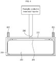
- FIG. 4 illustrates a side cross-sectional view of an ultrasonic inspection position during liquid-injection of a thermally conductive resin according to an embodiment of the present invention.
- FIG. 5 is a comparative drawing of an ultrasonic inspection method for determining whether a thermally conductive resin is filled or not according to an embodiment of the present invention.
- the ultrasonic inspection system determines whether the thermally conductive resin forming the thermally conductive resin layer 400 is filled or not through a waveform change of an ultrasonic wave measured by transmitting an ultrasonic wave toward a portion of an edge of the bottom surface 310 of the module frame from the outside.
- the thermally conductive resin liquid-injected into a checking hole when the thermally conductive resin liquid-injected into a checking hole is filled, a vision sensor recognizes this to adjust an amount of liquid-injection.
- the vision sensor has a problem in that detection power of the thermally conductive resin is low, and it is difficult to determine whether the thermally conductive resin is filled in a part other than the checking hole.
- the liquid-injection hole is formed in a center of the bottom surface of the module frame, there is a problem that it is not possible to check whether the thermally conductive resin is filled up to an edge of the bottom surface of the module frame far from the liquid-injection hole.
- thermally conductive resin when the thermally conductive resin is sufficiently liquid-injected, since the thermally conductive resin is cured after overflowing through the checking hole, a post-process is required to remove a portion that overflows through the checking hole and is cured, and an amount of the thermally conductive resin that overflows and then is cured may be lost.
- an ultrasonic wave is transmitted toward a part of an edge of the bottom surface 310 of the module frame, and a reflected wave of the transmitted ultrasonic wave is measured, so that since it is possible to check whether the thermally conductive resin forming the thermally conductive resin layer is filled up to an edge of the bottom surface of the module frame through a wave change of the measured ultrasonic wave, it is possible to accurately determine whether or not the thermally conductive resin is filled.
- the process of removing the thermally conductive resin that overflows and is cured through the checking hole may be omitted, and a material cost of the thermally conductive resin may be reduced by a removal amount of the thermally conductive resin that overflows and is cured.
- an ultrasonic sensor 600 for transmitting and sensing an ultrasonic wave may be disposed to contact the bottom surface 310 of the module frame at the outside of the module frame 300.
- a plurality of ultrasonic sensors 600 may be formed, and the plurality of ultrasonic sensors may be disposed at an edge of the bottom surface of the module frame.
- the thermally conductive resin layer 400 may be formed by liquid-injecting the thermally conductive resin through the liquid-injection hole 500 formed in the bottom surface 310 of the module frame, and a plurality of the liquid-injection holes 500 are arranged in a central portion of the bottom surface 310 of the module frame, so that a position at which the ultrasonic wave is transmitted may be a position spaced apart from the plurality of the liquid-injection holes 500. Therefore, it is possible to check whether the thermally conductive resin liquid-injected through the liquid-injection hole 500 is applied up to a position spaced from the liquid-injection hole 500 through a space between the battery cell stacked body 100 and the bottom surface 310 of the module frame by using the ultrasonic wave.
- FIG. 6 illustrates a flowchart of an ultrasonic inspection method according to an embodiment of the present invention.
- the ultrasonic inspection method includes liquid-injecting a thermally conductive resin through the liquid-injection hole 500 formed in the bottom surface 310 of the module frame (S100), stopping the liquid-injection of the thermally conductive resin (S200) and disposing an ultrasonic sensor on one portion (see FIG. 3 ) of an outer edge of the bottom surface 310 of the module frame (S300), transmitting an ultrasonic wave into the bottom surface 310 of the module frame through the ultrasonic sensor 600 (S400), and determining whether the thermally conductive resin is filled according to a waveform of the ultrasonic wave (S500).
- completing the liquid-injecting (S600) may be further included.
- thermally conductive resin when it is determined that the thermally conductive resin is not filled through the waveform of the ultrasonic wave (S520), additionally liquid-injecting the thermally conductive resin through the liquid-injection hole 500 (S700) may be further included.
- the ultrasonic sensor After the thermally conductive resin is additionally liquid-injected, the ultrasonic sensor is disposed again at a previously disposed position, and the ultrasonic wave may be transmitted to re-check whether the thermally conductive resin is filled at the corresponding position.
- disposing the ultrasonic sensor 600 on the other portion of the outer edge of the bottom surface 310 of the module frame and transmitting an ultrasonic wave to determine whether the thermally conductive resin is filled according to a waveform of the ultrasonic wave may be further included.
Landscapes
- Chemical & Material Sciences (AREA)
- Engineering & Computer Science (AREA)
- Manufacturing & Machinery (AREA)
- Chemical Kinetics & Catalysis (AREA)
- Electrochemistry (AREA)
- General Chemical & Material Sciences (AREA)
- Physics & Mathematics (AREA)
- Mechanical Engineering (AREA)
- Acoustics & Sound (AREA)
- General Physics & Mathematics (AREA)
- Biochemistry (AREA)
- Analytical Chemistry (AREA)
- Life Sciences & Earth Sciences (AREA)
- General Health & Medical Sciences (AREA)
- Health & Medical Sciences (AREA)
- Immunology (AREA)
- Pathology (AREA)
- Electromagnetism (AREA)
- Thermal Sciences (AREA)
- Fluid Mechanics (AREA)
- Investigating Or Analyzing Materials By The Use Of Ultrasonic Waves (AREA)
- Secondary Cells (AREA)
- Battery Mounting, Suspending (AREA)
- Sealing Battery Cases Or Jackets (AREA)
Abstract
Description
- This application claims priority to and the benefit of
Korean Patent Application No. 10-2020-0060502 filed in the Korean Intellectual Property Office on May 20, 2020 - The present invention relates to an ultrasonic inspection system and method, and more particularly, to an ultrasonic non-destructive inspection system and method that may check whether a battery module is filled with a thermally conductive resin.
- A secondary battery has attracted a great deal of attention as an energy source in various products such as a mobile device and an electric vehicle. The secondary battery is a strong energy source that may replace use of existing products that use fossil fuels, and is being highlighted as an environmentally friendly energy source because no by-products are generated according to energy use.
- Recently, as needs for a large-capacity secondary battery structure along with use of the secondary battery as an energy storage source are increasing, there is an increasing demand for a battery pack having a multi-module structure in which a battery module in which a plurality of secondary batteries are connected in series/parallel is assembled in plural.
- Meanwhile, when configuring a battery pack by connecting a plurality of battery cells in series/parallel, a method of configuring a battery module consisting of at least one battery cell and then configuring a battery pack by adding other components to at least one battery module is generally used.
- The battery module includes a battery cell stacked body in which a plurality of battery cells are stacked, a module frame accommodating the battery cell stacked body, and a thermally conductive resin layer formed by injecting between the battery cell stacked body and the module frame.
- The thermally conductive resin layer mainly serves to perform a cooling function that transmits heat generated inside the battery module to the outside, and thus, after liquid-injecting the thermally conductive resin into the battery module, inspecting whether the thermally conductive resin is properly applied to a bottom surface of the module frame is essentially required.
- Conventionally, while the thermally conductive resin that has been liquid-injected into a checking hole formed on the bottom surface of the module frame is being filled, a vision sensor recognizes this to adjust a liquid-injection amount of the thermally conductive resin. However, the vision sensor has a problem in that detection power itself is poor and it is difficult to check whether parts other than the checking hole are filled. In addition, after the thermally conductive resin is cured, a post-process is required to remove the thermally conductive resin that has overflown in the checking hole, which may result in loss of the thermally conductive resin.
- The present invention has been made in an effort to provide an ultrasonic inspection system and method that may accurately check an applied state of a thermally conductive resin layer formed inside a battery module while preventing loss of a thermally conductive resin.
- The objects of the present invention are not limited to the objects mentioned above, and other objects not mentioned can be clearly understood by those skilled in the art from the description below.
- An embodiment of the present invention provides an ultrasonic inspection system, including: a battery module that includes a battery cell stacked body in which a plurality of battery cells are stacked; a module frame accommodating the battery cell stacked body; and a thermally conductive resin layer formed by liquid-injecting it between a lower end of the battery cell stacked body and a bottom surface of the module frame, wherein the ultrasonic inspection system determines whether or not a thermally conductive resin forming the thermally conductive resin layer is filled through a waveform change of an ultrasonic wave measured by transmitting the ultrasonic wave toward a portion of an edge of the bottom surface of the module frame from the outside..
- An ultrasonic sensor that transmits and senses the ultrasonic wave may be disposed to contact the bottom surface of the module frame at the outside of the module frame.
- A plurality of the ultrasonic sensors may be formed, and the plurality of ultrasonic sensors may be disposed at an edge of the bottom surface of the module frame.
- The thermally conductive resin layer may be formed by liquid-injecting a thermally conductive resin through a liquid-injection hole formed in the bottom surface of the module frame.
- A plurality of the liquid-injection holes may be arranged in a central portion of the bottom surface of the module frame.
- A position from which the ultrasonic wave is transmitted may be a position spaced apart from the plurality of the liquid-injection holes.
- Another embodiment of the present invention provides an ultrasonic inspection method, including: liquid-injecting a thermally conductive resin through a liquid-injection hole formed in a bottom surface of a module frame; stopping the liquid-injecting of the thermally conductive resin and disposing an ultrasonic sensor on one portion of an outer edge of the bottom surface of the module frame; transmitting an ultrasonic wave into the bottom surface of the module frame through the ultrasonic sensor; and determining whether the thermally conductive resin is filled according to a waveform of the ultrasonic wave.
- When it is determined that the thermally conductive resin is filled through the waveform of the ultrasonic wave, completing the liquid-injecting may be further included.
- When it is determined that the thermally conductive resin is not filled through the waveform of the ultrasonic wave, additionally liquid-injecting the thermally conductive resin through the liquid-injection hole may be further included.
- After the determining of whether the thermally conductive resin is filled according to the waveform of the ultrasonic wave, disposing the ultrasonic sensor on the other portion of the outer edge of the bottom surface of the module frame and transmitting an ultrasonic wave to determine whether the thermally conductive resin is filled according to a waveform of the ultrasonic wave may be further included.
- The ultrasonic inspection system and method according to the embodiment of the present invention provide an effect of accurately determining whether a thermally conductive resin is filled by using an ultrasonic sensor.
- The effects of the present invention are not limited to the effects mentioned above, and other effects not mentioned can be clearly understood by those skilled in the art from the description of the claims.
-
-
FIG. 1 illustrates an exploded perspective view of a battery module according to an embodiment of the present invention. -
FIG. 2 illustrates a perspective view of a bottom surface of a battery module according to an embodiment of the present invention. -
FIG. 3 illustrates a position of an ultrasonic sensor according to an embodiment of the present invention. -
FIG. 4 illustrates a side cross-sectional view of an ultrasonic inspection position during liquid-injection of a thermally conductive resin according to an embodiment of the present invention. -
FIG. 5 is a comparative drawing of an ultrasonic inspection method for determining whether a thermally conductive resin is filled or not according to an embodiment of the present invention. -
FIG. 6 illustrates a flowchart of an ultrasonic inspection method according to an embodiment of the present invention. - Embodiments described below are exemplarily illustrated for understanding of the invention, and it should be understood that the present invention may be modified in various ways to be different from the embodiments described herein. However, in the description of the present invention, the detailed description and illustration of related well-known functions or constituent elements will be omitted when it is determined as unnecessarily making the scope of the present invention unclear.
- The terms "first", "second", etc. used in the present specification may be used to describe various constituent elements, but the constituent elements should not be limited to the terms. The terms should be used only for differentiating one constituent element from another constituent element.
- The terms used in the specification are used to describe only specific embodiments and are not intended to limit the scope of the present invention. Singular forms are intended to include plural forms unless the context clearly indicates otherwise. In the present specification, it should be understood that the term "include", "comprise", "have", or "configure" indicates that a feature, a number, a step, an operation, a component, a part, or a combination thereof described in the specification is present, but does not exclude a possibility of presence or addition of one or more other features, numbers, steps, operations, components, parts, or combinations, in advance.
- Hereinafter, a battery module according to an embodiment of the present invention will be described with reference to
FIG. 1 andFIG. 2 . -
FIG. 1 illustrates an exploded perspective view of a battery module according to an embodiment of the present invention.FIG. 2 illustrates a perspective view of a bottom surface of a battery module according to an embodiment of the present invention. - Referring to
FIG. 1 andFIG. 2 , the battery module according to the present embodiment includes a battery cell stackedbody 100 in which a plurality of battery cells are stacked, amodule frame 300 for accommodating the battery cell stackedbody 100, and a thermallyconductive resin layer 400 formed by liquid-injecting a thermally conductive resin between a lower end of the battery cell stackedbody 100 and a bottom surface of themodule frame 300. - The battery cell is a secondary battery, and may be configured as a pouch-type of secondary battery. A plurality of battery cells may be configured, and the plurality of battery cells may be stacked on each other to be electrically connected to each other to form the battery cell stacked
body 100. Each of the plurality of battery cells may include an electrode assembly, a battery case, and an electrode lead protruding from the electrode assembly. - A bus
bar frame assembly 200 is formed on front and rear surfaces and an upper surface of thebattery cell stack 100. The busbar frame assembly 200 is formed with abus bar frame 210 that covers the front and rear surfaces of the battery cell stackedbody 100 and electrically connects electrode leads of a plurality of battery cells, and anupper plate 220 that covers the upper surface of the battery cell stackedbody 100 and connects thebus bar frames 210 at both ends thereof. A flexible circuit board is provided at a lower surface of theupper plate 220, so that the bus bar frames at both ends may be electrically connected to each other. - The
module frame 300 is formed with upper, lower, left, and right surfaces to accommodate the battery cell stackedbody 100 and the busbar frame assembly 200. Compression pads are formed at portions in which the outermost battery cells of the battery cell stackedbody 100 meet the left and right surfaces of the frame, respectively, to absorb a tolerance between themodule frame 300 and the battery cells when swelling of the battery cells occurs. - When the battery cell stacked
body 100 and the busbar frame assembly 200 are accommodated in themodule frame 300, anend plate 320 is coupled to the front and rear surfaces of themodule frame 300 to cover the front and rear surfaces of the battery cell stackedbody 100. Through this, electronic components inside themodule frame 300 may be protected, and the battery module may be mounted on the battery pack through a mounting structure formed on theend plate 320. - The thermally
conductive resin layer 400 may be formed by injecting a thermally conductive resin between a lower end of the battery cell stackedbody 100 and abottom surface 310 of themodule frame 300. The thermally conductive resin may be formed of a thermal resin. A sufficient amount of the thermallyconductive resin layer 400 may be liquid-injected so as to contact lower ends of a plurality of battery cells of the battery cell stackedbody 100. By transmitting heat generated in the battery cell stackedbody 100 through the thermallyconductive resin layer 400 and dissipating it to the outside, a cooling function of the battery module may be performed. - The thermally
conductive resin layer 400 may be formed by liquid-injecting a thermally conductive resin through a liquid-injection hole 500 formed in the bottom surface of themodule frame 300 as shown inFIG. 2 . In this case, a plurality of liquid-injection holes 500 may be arranged on a central portion of thebottom surface 310 of themodule frame 300. The thermally conductive resin may be formed of a thermal resin. - Hereinafter, an ultrasonic inspection system according to an embodiment of the present invention will be described with reference to
FIG. 3 to FIG. 5 . -
FIG. 3 illustrates a position of an ultrasonic sensor according to an embodiment of the present invention.FIG. 4 illustrates a side cross-sectional view of an ultrasonic inspection position during liquid-injection of a thermally conductive resin according to an embodiment of the present invention.FIG. 5 is a comparative drawing of an ultrasonic inspection method for determining whether a thermally conductive resin is filled or not according to an embodiment of the present invention. - Referring to
FIG. 3 to FIG. 5 , the ultrasonic inspection system according to the present embodiment determines whether the thermally conductive resin forming the thermallyconductive resin layer 400 is filled or not through a waveform change of an ultrasonic wave measured by transmitting an ultrasonic wave toward a portion of an edge of thebottom surface 310 of the module frame from the outside. - Conventionally, when the thermally conductive resin liquid-injected into a checking hole is filled, a vision sensor recognizes this to adjust an amount of liquid-injection. However, the vision sensor has a problem in that detection power of the thermally conductive resin is low, and it is difficult to determine whether the thermally conductive resin is filled in a part other than the checking hole. Particularly, since the liquid-injection hole is formed in a center of the bottom surface of the module frame, there is a problem that it is not possible to check whether the thermally conductive resin is filled up to an edge of the bottom surface of the module frame far from the liquid-injection hole.
- In addition, when the thermally conductive resin is sufficiently liquid-injected, since the thermally conductive resin is cured after overflowing through the checking hole, a post-process is required to remove a portion that overflows through the checking hole and is cured, and an amount of the thermally conductive resin that overflows and then is cured may be lost.
- Meanwhile, according to the present embodiment, an ultrasonic wave is transmitted toward a part of an edge of the
bottom surface 310 of the module frame, and a reflected wave of the transmitted ultrasonic wave is measured, so that since it is possible to check whether the thermally conductive resin forming the thermally conductive resin layer is filled up to an edge of the bottom surface of the module frame through a wave change of the measured ultrasonic wave, it is possible to accurately determine whether or not the thermally conductive resin is filled. - In addition, since it is possible to check whether the thermally conductive resin is filled inside the battery module with only the ultrasonic sensor, no method of measuring the presence or absence of filling through the checking hole is required, so that it is possible to reduce a processing cost of the conventional check hole, the process of removing the thermally conductive resin that overflows and is cured through the checking hole may be omitted, and a material cost of the thermally conductive resin may be reduced by a removal amount of the thermally conductive resin that overflows and is cured.
- According to the present embodiment, as shown in
FIG. 4 , anultrasonic sensor 600 for transmitting and sensing an ultrasonic wave may be disposed to contact thebottom surface 310 of the module frame at the outside of themodule frame 300. A plurality ofultrasonic sensors 600 may be formed, and the plurality of ultrasonic sensors may be disposed at an edge of the bottom surface of the module frame. - The thermally
conductive resin layer 400 may be formed by liquid-injecting the thermally conductive resin through the liquid-injection hole 500 formed in thebottom surface 310 of the module frame, and a plurality of the liquid-injection holes 500 are arranged in a central portion of thebottom surface 310 of the module frame, so that a position at which the ultrasonic wave is transmitted may be a position spaced apart from the plurality of the liquid-injection holes 500. Therefore, it is possible to check whether the thermally conductive resin liquid-injected through the liquid-injection hole 500 is applied up to a position spaced from the liquid-injection hole 500 through a space between the battery cell stackedbody 100 and thebottom surface 310 of the module frame by using the ultrasonic wave. - Referring to
FIG. 5 , in the portion where the thermally conductive resin is not filled inside the battery module, a waveform unique to aluminum, which is a material of thebottom surface 310 of the module frame, is observed, but in the portion where the thermally conductive resin is filled, a waveform disappears, that is, a waveform difference occurs. Through this, by contacting theultrasonic sensor 600 to a specific position of thebottom surface 310 of the module frame, it is possible to determine whether the thermally conductive resin is filled therein. - Hereinafter, an ultrasonic inspection method according to an embodiment of the present invention will be described with reference to
FIG. 6 . -
FIG. 6 illustrates a flowchart of an ultrasonic inspection method according to an embodiment of the present invention. - Referring to
FIG. 4 andFIG. 6 , the ultrasonic inspection method according to the present embodiment includes liquid-injecting a thermally conductive resin through the liquid-injection hole 500 formed in thebottom surface 310 of the module frame (S100), stopping the liquid-injection of the thermally conductive resin (S200) and disposing an ultrasonic sensor on one portion (seeFIG. 3 ) of an outer edge of thebottom surface 310 of the module frame (S300), transmitting an ultrasonic wave into thebottom surface 310 of the module frame through the ultrasonic sensor 600 (S400), and determining whether the thermally conductive resin is filled according to a waveform of the ultrasonic wave (S500). - According to the present embodiment, when it is determined that the thermally conductive resin is filled through the waveform of the ultrasonic wave, completing the liquid-injecting (S600) may be further included.
- In addition, according to the present embodiment, when it is determined that the thermally conductive resin is not filled through the waveform of the ultrasonic wave (S520), additionally liquid-injecting the thermally conductive resin through the liquid-injection hole 500 (S700) may be further included. After the thermally conductive resin is additionally liquid-injected, the ultrasonic sensor is disposed again at a previously disposed position, and the ultrasonic wave may be transmitted to re-check whether the thermally conductive resin is filled at the corresponding position.
- In addition, according to the present embodiment, when it is determined that the thermally conductive resin is filled through the waveform of the ultrasonic wave, completing the liquid-injecting (S600) may be further included.
- Further, according to the present embodiment, after the determining of whether the thermally conductive resin is filled according to the waveform of the ultrasonic wave, disposing the
ultrasonic sensor 600 on the other portion of the outer edge of thebottom surface 310 of the module frame and transmitting an ultrasonic wave to determine whether the thermally conductive resin is filled according to a waveform of the ultrasonic wave may be further included. Through this, it is possible to check whether the thermally conductive resin is filled or not at several points on the bottom surface of themodule frame 310, so that it is possible to more accurately determine whether the thermally conductive resin is filled or not. - In the foregoing description, the embodiments of the present invention have been illustrated and described, but the present invention is not limited to the specific embodiments, and it will be apparent to those skilled in the art that various modifications and variations may be made without departing from the spirit or scope of the invention, and thus, it is intended that the present invention cover the modifications and variations of this invention provided they come within the scope of the appended claims and their equivalents.
-
- 100:
- battery cell stacked body
- 200:
- bus bar frame assembly
- 300:
- module frame
- 310:
- bottom surface of module frame
- 320:
- end plate
- 400:
- thermally conductive resin layer
- 500:
- liquid-injection hole
- 600:
- ultrasonic sensor
Claims (10)
- An ultrasonic inspection system, comprising:a battery module that includes a battery cell stacked body in which a plurality of battery cells are stacked; a module frame accommodating the battery cell stacked body; and a thermally conductive resin layer formed by liquid-injecting it between a lower end of the battery cell stacked body and a bottom surface of the module frame,wherein the ultrasonic inspection system determines whether or not a thermally conductive resin forming the thermally conductive resin layer is filled through a waveform change of an ultrasonic wave measured by transmitting the ultrasonic wave toward a portion of an edge of the bottom surface of the module frame from the outside.
- The ultrasonic inspection system of claim 1, wherein
an ultrasonic sensor that transmits and senses the ultrasonic wave is disposed to contact the bottom surface of the module frame at the outside of the module frame. - The ultrasonic inspection system of claim 2, wherein
a plurality of the ultrasonic sensors are formed, and the plurality of ultrasonic sensors are disposed at an edge of the bottom surface of the module frame. - The ultrasonic inspection system of claim 1, wherein
the thermally conductive resin layer is formed by liquid-injecting a thermally conductive resin through a liquid-injection hole formed in the bottom surface of the module frame. - The ultrasonic inspection system of claim 4, wherein
a plurality of the liquid-injection holes are arranged in a central portion of the bottom surface of the module frame. - The ultrasonic inspection system of claim 5, wherein
a position from which the ultrasonic wave is transmitted is a position spaced apart from the plurality of the liquid-injection holes. - An ultrasonic inspection method, comprising:liquid-injecting a thermally conductive resin through a liquid-injection hole formed in a bottom surface of a module frame;stopping the liquid-injecting of the thermally conductive resin and disposing an ultrasonic sensor on one portion of an outer edge of the bottom surface of the module frame;transmitting an ultrasonic wave into the bottom surface of the module frame through the ultrasonic sensor; anddetermining whether the thermally conductive resin is filled according to a waveform of the ultrasonic wave.
- The ultrasonic inspection method of claim 7, further comprising
when it is determined that the thermally conductive resin is filled through the waveform of the ultrasonic wave, completing the liquid-injecting. - The ultrasonic inspection method of claim 7, further comprising
when it is determined that the thermally conductive resin is not filled through the waveform of the ultrasonic wave, additionally liquid-injecting the thermally conductive resin through the liquid-injection hole. - The ultrasonic inspection method of claim 7, further comprising
after the determining of whether the thermally conductive resin is filled according to the waveform of the ultrasonic wave, disposing the ultrasonic sensor on the other portion of the outer edge of the bottom surface of the module frame and transmitting an ultrasonic wave to determine whether the thermally conductive resin is filled according to a waveform of the ultrasonic wave.
Applications Claiming Priority (2)
| Application Number | Priority Date | Filing Date | Title |
|---|---|---|---|
| KR1020200060502A KR102917122B1 (en) | 2020-05-20 | 2020-05-20 | System and method for ultrasonic inspection |
| PCT/KR2021/005320 WO2021235718A1 (en) | 2020-05-20 | 2021-04-27 | System and method for ultrasonic inspection |
Publications (2)
| Publication Number | Publication Date |
|---|---|
| EP4016696A1 true EP4016696A1 (en) | 2022-06-22 |
| EP4016696A4 EP4016696A4 (en) | 2024-01-10 |
Family
ID=78698056
Family Applications (1)
| Application Number | Title | Priority Date | Filing Date |
|---|---|---|---|
| EP21808839.1A Pending EP4016696A4 (en) | 2020-05-20 | 2021-04-27 | SYSTEM AND METHOD FOR ULTRASONIC INSPECTION |
Country Status (6)
| Country | Link |
|---|---|
| US (1) | US12384085B2 (en) |
| EP (1) | EP4016696A4 (en) |
| JP (1) | JP7438600B2 (en) |
| KR (1) | KR102917122B1 (en) |
| CN (1) | CN114450138A (en) |
| WO (1) | WO2021235718A1 (en) |
Families Citing this family (1)
| Publication number | Priority date | Publication date | Assignee | Title |
|---|---|---|---|---|
| CN119944148B (en) * | 2024-12-16 | 2025-12-12 | 比亚迪股份有限公司 | Cold plate, monitoring device, monitoring system and monitoring method |
Family Cites Families (29)
| Publication number | Priority date | Publication date | Assignee | Title |
|---|---|---|---|---|
| JPH01195012A (en) | 1988-01-30 | 1989-08-04 | Amada Co Ltd | Switching process of injection dwell pressure of injection molding machine and its device |
| JPH02162254A (en) * | 1988-12-15 | 1990-06-21 | Nissan Motor Co Ltd | Non-destructive inspection of multilayer resin molded product |
| JPH03138123A (en) | 1989-10-24 | 1991-06-12 | Sekisui Chem Co Ltd | Feeding method for filling time in injection molding |
| JPH095305A (en) | 1995-06-16 | 1997-01-10 | Daido Steel Co Ltd | Defect inspection method and device |
| JP2000205931A (en) | 1999-01-18 | 2000-07-28 | Toyota Motor Corp | Ultrasonic liquid level inspection equipment |
| JP2000221173A (en) | 1999-01-28 | 2000-08-11 | Ohbayashi Corp | Method and apparatus for non-destructive inspection of bonded surface |
| JP2001085062A (en) | 1999-09-20 | 2001-03-30 | Showa Denko Kk | Inspecting method for electrochemical element and manufacture of electrochemical element |
| JP2001194134A (en) * | 2000-01-11 | 2001-07-19 | Nkk Corp | Method and apparatus for measuring thickness of resin material |
| JP4801338B2 (en) | 2004-10-06 | 2011-10-26 | 三菱重工業株式会社 | RTM mold and RTM molding method |
| JP5173227B2 (en) | 2007-03-30 | 2013-04-03 | 三洋電機株式会社 | Pack battery |
| JP5287309B2 (en) * | 2009-02-05 | 2013-09-11 | トヨタ自動車株式会社 | Immersion inspection device |
| JP2012069267A (en) | 2010-09-21 | 2012-04-05 | Nissan Motor Co Ltd | Battery internal state detection device |
| JP2014082020A (en) | 2012-10-12 | 2014-05-08 | Sharp Corp | Battery manufacturing method |
| US10078069B2 (en) | 2014-11-24 | 2018-09-18 | Electronics And Telecommunications Research Institute | Device for detecting change in underground medium |
| KR102217681B1 (en) | 2014-11-24 | 2021-02-22 | 한국전자통신연구원 | Underground medium detecting device |
| FR3031062B1 (en) | 2014-12-24 | 2017-09-15 | Airbus Group Sas | ULTRASONIC INJECTION RESIN FLOW / INJECTION RESIN FLOW QUANTIFICATION DEVICE AND METHOD USING SUCH A DEVICE |
| CN107112607B (en) * | 2015-01-16 | 2020-08-11 | 株式会社村田制作所 | Power storage modules, power storage systems, electronic devices, electric vehicles, and power systems |
| KR101941117B1 (en) | 2015-02-27 | 2019-01-23 | 주식회사 엘지화학 | Battery module |
| JP6394480B2 (en) | 2015-04-27 | 2018-09-26 | トヨタ自動車株式会社 | Manufacturing method of all solid state battery |
| KR102039526B1 (en) | 2016-07-12 | 2019-11-01 | 주식회사 엘지화학 | Device and method for inspection of sealing performance of pouch type secondary battery |
| KR102207881B1 (en) | 2017-01-17 | 2021-01-25 | 주식회사 엘지화학 | Battery module, battery pack comprising the battery module and vehicle comprising the battery pack |
| KR102201348B1 (en) | 2017-01-17 | 2021-01-08 | 주식회사 엘지화학 | Fabricating method of battery module |
| JP6787254B2 (en) * | 2017-05-31 | 2020-11-18 | 株式会社豊田自動織機 | Power storage module manufacturing equipment and manufacturing method |
| JP6986378B2 (en) | 2017-06-30 | 2021-12-22 | 三菱重工業株式会社 | Piping removal method |
| WO2019013508A1 (en) * | 2017-07-10 | 2019-01-17 | 주식회사 엘지화학 | BATTERY MODULE HOUSING AND BATTERY MODULE COMPRISING SAME |
| JP7091699B2 (en) * | 2018-02-21 | 2022-06-28 | セイコーエプソン株式会社 | Manufacturing method of ultrasonic sensor, ultrasonic device, and ultrasonic sensor |
| KR102324868B1 (en) * | 2018-07-27 | 2021-11-09 | 주식회사 엘지에너지솔루션 | Battery module, battery pack comprising the battery module and vehicle comprising the battery pack |
| JP2020082502A (en) | 2018-11-24 | 2020-06-04 | エフ・アール・ピー・サービス株式会社 | Nondestructive inspection method for resin impregnation process |
| FR3092168B1 (en) * | 2019-01-24 | 2021-08-06 | Dehon Sa | System and method for measuring by acoustic waves the filling level of a fluid reservoir |
-
2020
- 2020-05-20 KR KR1020200060502A patent/KR102917122B1/en active Active
-
2021
- 2021-04-27 WO PCT/KR2021/005320 patent/WO2021235718A1/en not_active Ceased
- 2021-04-27 JP JP2022516362A patent/JP7438600B2/en active Active
- 2021-04-27 US US17/762,545 patent/US12384085B2/en active Active
- 2021-04-27 EP EP21808839.1A patent/EP4016696A4/en active Pending
- 2021-04-27 CN CN202180005454.6A patent/CN114450138A/en active Pending
Also Published As
| Publication number | Publication date |
|---|---|
| JP2022548610A (en) | 2022-11-21 |
| US20220339836A1 (en) | 2022-10-27 |
| KR20210143565A (en) | 2021-11-29 |
| US12384085B2 (en) | 2025-08-12 |
| JP7438600B2 (en) | 2024-02-27 |
| WO2021235718A1 (en) | 2021-11-25 |
| EP4016696A4 (en) | 2024-01-10 |
| KR102917122B1 (en) | 2026-01-22 |
| CN114450138A (en) | 2022-05-06 |
Similar Documents
| Publication | Publication Date | Title |
|---|---|---|
| EP3258517B1 (en) | Battery module having improved fastening structure | |
| EP2838135B1 (en) | Rechargeable battery pack | |
| US20200112014A1 (en) | Battery Module Having Bus Bar Assembly | |
| KR102029422B1 (en) | Battery pack temperature detection sensor unit and Monitoring device of energy storage system with the same | |
| KR102924944B1 (en) | Battery module comprising temperature sensor | |
| KR20200144423A (en) | Battery module and battery pack including the same | |
| EP3920307B1 (en) | Battery module, battery pack and device | |
| KR102772766B1 (en) | Battery module and battery pack including the same | |
| US12494541B2 (en) | Battery module and battery pack including the same | |
| EP4016696A1 (en) | System and method for ultrasonic inspection | |
| KR102798589B1 (en) | Battery module and battery pack including the same | |
| EP3972035A1 (en) | Pouch cell battery assembly | |
| KR20220067119A (en) | Battery module and battery pack including the same | |
| US11876249B2 (en) | Conductive module | |
| CN115917834B (en) | Battery module, battery pack including the battery module, and electric vehicle | |
| JP7278680B2 (en) | A pouch-type secondary battery containing a pressure sensing device that measures the internal pressure | |
| EP4517924A1 (en) | Temperature sensing assembly, and battery module comprising same | |
| JP7805466B2 (en) | Battery cell assembly including a thermistor and method of manufacturing the same | |
| CN118633196A (en) | Battery Module | |
| KR20250049127A (en) | Battery module | |
| KR20260038363A (en) | Busbar frame assembly and battery assembly including the same | |
| KR20240127182A (en) | Battery system assembly | |
| EP4704227A1 (en) | Battery cell and battery module | |
| KR20210116040A (en) | Battery module including novel sensing structure and battery pack comprising the same | |
| CN118476083A (en) | Battery module, battery pack, and energy storage system |
Legal Events
| Date | Code | Title | Description |
|---|---|---|---|
| STAA | Information on the status of an ep patent application or granted ep patent |
Free format text: STATUS: THE INTERNATIONAL PUBLICATION HAS BEEN MADE |
|
| PUAI | Public reference made under article 153(3) epc to a published international application that has entered the european phase |
Free format text: ORIGINAL CODE: 0009012 |
|
| STAA | Information on the status of an ep patent application or granted ep patent |
Free format text: STATUS: REQUEST FOR EXAMINATION WAS MADE |
|
| 17P | Request for examination filed |
Effective date: 20220316 |
|
| AK | Designated contracting states |
Kind code of ref document: A1 Designated state(s): AL AT BE BG CH CY CZ DE DK EE ES FI FR GB GR HR HU IE IS IT LI LT LU LV MC MK MT NL NO PL PT RO RS SE SI SK SM TR |
|
| DAV | Request for validation of the european patent (deleted) | ||
| DAX | Request for extension of the european patent (deleted) | ||
| A4 | Supplementary search report drawn up and despatched |
Effective date: 20231207 |
|
| RIC1 | Information provided on ipc code assigned before grant |
Ipc: H01M 50/609 20210101ALI20231201BHEP Ipc: H01M 50/211 20210101ALI20231201BHEP Ipc: H01M 10/48 20060101ALI20231201BHEP Ipc: B29L 31/34 20060101ALI20231201BHEP Ipc: B29C 45/14 20060101ALI20231201BHEP Ipc: H01M 50/20 20210101ALI20231201BHEP Ipc: H01M 10/647 20140101ALI20231201BHEP Ipc: G01N 29/032 20060101ALI20231201BHEP Ipc: H01M 10/653 20140101ALI20231201BHEP Ipc: G01N 29/04 20060101ALI20231201BHEP Ipc: H01M 10/42 20060101AFI20231201BHEP |