EP4016683A1 - Electrode assembly and preparation method thereof - Google Patents
Electrode assembly and preparation method thereof Download PDFInfo
- Publication number
- EP4016683A1 EP4016683A1 EP20873712.2A EP20873712A EP4016683A1 EP 4016683 A1 EP4016683 A1 EP 4016683A1 EP 20873712 A EP20873712 A EP 20873712A EP 4016683 A1 EP4016683 A1 EP 4016683A1
- Authority
- EP
- European Patent Office
- Prior art keywords
- negative electrode
- collector
- exposed portion
- positive electrode
- electrode
- Prior art date
- Legal status (The legal status is an assumption and is not a legal conclusion. Google has not performed a legal analysis and makes no representation as to the accuracy of the status listed.)
- Pending
Links
- 238000002360 preparation method Methods 0.000 title 1
- 238000004804 winding Methods 0.000 claims abstract description 57
- 239000007773 negative electrode material Substances 0.000 claims abstract description 40
- 235000015110 jellies Nutrition 0.000 claims abstract description 3
- 239000008274 jelly Substances 0.000 claims abstract description 3
- 238000000034 method Methods 0.000 claims description 21
- 238000004519 manufacturing process Methods 0.000 claims description 20
- 239000007774 positive electrode material Substances 0.000 claims description 19
- 230000000052 comparative effect Effects 0.000 description 24
- 102100028667 C-type lectin domain family 4 member A Human genes 0.000 description 5
- 101000766908 Homo sapiens C-type lectin domain family 4 member A Proteins 0.000 description 5
- 238000000429 assembly Methods 0.000 description 4
- 230000000712 assembly Effects 0.000 description 4
- 238000002474 experimental method Methods 0.000 description 4
- 238000007599 discharging Methods 0.000 description 3
- 239000000463 material Substances 0.000 description 3
- WHXSMMKQMYFTQS-UHFFFAOYSA-N Lithium Chemical compound [Li] WHXSMMKQMYFTQS-UHFFFAOYSA-N 0.000 description 2
- 230000008901 benefit Effects 0.000 description 2
- 230000003247 decreasing effect Effects 0.000 description 2
- 230000005611 electricity Effects 0.000 description 2
- 229910052744 lithium Inorganic materials 0.000 description 2
- 238000007254 oxidation reaction Methods 0.000 description 2
- 238000006722 reduction reaction Methods 0.000 description 2
- 239000002699 waste material Substances 0.000 description 2
- 238000003466 welding Methods 0.000 description 2
- HBBGRARXTFLTSG-UHFFFAOYSA-N Lithium ion Chemical compound [Li+] HBBGRARXTFLTSG-UHFFFAOYSA-N 0.000 description 1
- 230000008859 change Effects 0.000 description 1
- 238000006243 chemical reaction Methods 0.000 description 1
- 239000011248 coating agent Substances 0.000 description 1
- 238000000576 coating method Methods 0.000 description 1
- 238000007796 conventional method Methods 0.000 description 1
- 230000006866 deterioration Effects 0.000 description 1
- 230000000694 effects Effects 0.000 description 1
- 239000007772 electrode material Substances 0.000 description 1
- 239000003792 electrolyte Substances 0.000 description 1
- 229910001416 lithium ion Inorganic materials 0.000 description 1
- 229910021450 lithium metal oxide Inorganic materials 0.000 description 1
- 238000012986 modification Methods 0.000 description 1
- 230000004048 modification Effects 0.000 description 1
- 230000003647 oxidation Effects 0.000 description 1
- 230000002265 prevention Effects 0.000 description 1
- 230000009467 reduction Effects 0.000 description 1
- 238000011946 reduction process Methods 0.000 description 1
- 230000009291 secondary effect Effects 0.000 description 1
- 238000004904 shortening Methods 0.000 description 1
- 239000000126 substance Substances 0.000 description 1
Images


Classifications
-
- H—ELECTRICITY
- H01—ELECTRIC ELEMENTS
- H01M—PROCESSES OR MEANS, e.g. BATTERIES, FOR THE DIRECT CONVERSION OF CHEMICAL ENERGY INTO ELECTRICAL ENERGY
- H01M10/00—Secondary cells; Manufacture thereof
- H01M10/04—Construction or manufacture in general
- H01M10/0431—Cells with wound or folded electrodes
-
- H—ELECTRICITY
- H01—ELECTRIC ELEMENTS
- H01M—PROCESSES OR MEANS, e.g. BATTERIES, FOR THE DIRECT CONVERSION OF CHEMICAL ENERGY INTO ELECTRICAL ENERGY
- H01M50/00—Constructional details or processes of manufacture of the non-active parts of electrochemical cells other than fuel cells, e.g. hybrid cells
- H01M50/50—Current conducting connections for cells or batteries
- H01M50/531—Electrode connections inside a battery casing
- H01M50/538—Connection of several leads or tabs of wound or folded electrode stacks
-
- H—ELECTRICITY
- H01—ELECTRIC ELEMENTS
- H01M—PROCESSES OR MEANS, e.g. BATTERIES, FOR THE DIRECT CONVERSION OF CHEMICAL ENERGY INTO ELECTRICAL ENERGY
- H01M8/00—Fuel cells; Manufacture thereof
- H01M8/02—Details
- H01M8/0202—Collectors; Separators, e.g. bipolar separators; Interconnectors
- H01M8/0204—Non-porous and characterised by the material
- H01M8/0223—Composites
- H01M8/0228—Composites in the form of layered or coated products
-
- H—ELECTRICITY
- H01—ELECTRIC ELEMENTS
- H01M—PROCESSES OR MEANS, e.g. BATTERIES, FOR THE DIRECT CONVERSION OF CHEMICAL ENERGY INTO ELECTRICAL ENERGY
- H01M2250/00—Fuel cells for particular applications; Specific features of fuel cell system
- H01M2250/20—Fuel cells in motive systems, e.g. vehicle, ship, plane
-
- Y—GENERAL TAGGING OF NEW TECHNOLOGICAL DEVELOPMENTS; GENERAL TAGGING OF CROSS-SECTIONAL TECHNOLOGIES SPANNING OVER SEVERAL SECTIONS OF THE IPC; TECHNICAL SUBJECTS COVERED BY FORMER USPC CROSS-REFERENCE ART COLLECTIONS [XRACs] AND DIGESTS
- Y02—TECHNOLOGIES OR APPLICATIONS FOR MITIGATION OR ADAPTATION AGAINST CLIMATE CHANGE
- Y02E—REDUCTION OF GREENHOUSE GAS [GHG] EMISSIONS, RELATED TO ENERGY GENERATION, TRANSMISSION OR DISTRIBUTION
- Y02E60/00—Enabling technologies; Technologies with a potential or indirect contribution to GHG emissions mitigation
- Y02E60/10—Energy storage using batteries
-
- Y—GENERAL TAGGING OF NEW TECHNOLOGICAL DEVELOPMENTS; GENERAL TAGGING OF CROSS-SECTIONAL TECHNOLOGIES SPANNING OVER SEVERAL SECTIONS OF THE IPC; TECHNICAL SUBJECTS COVERED BY FORMER USPC CROSS-REFERENCE ART COLLECTIONS [XRACs] AND DIGESTS
- Y02—TECHNOLOGIES OR APPLICATIONS FOR MITIGATION OR ADAPTATION AGAINST CLIMATE CHANGE
- Y02P—CLIMATE CHANGE MITIGATION TECHNOLOGIES IN THE PRODUCTION OR PROCESSING OF GOODS
- Y02P70/00—Climate change mitigation technologies in the production process for final industrial or consumer products
- Y02P70/50—Manufacturing or production processes characterised by the final manufactured product
Definitions
- the present invention relates to an electrode assembly and a method for manufacturing same and, more specifically, to: an electrode assembly in which a gap between a point, where application of a positive electrode active material starts in a central region (in a starting end) of a jelly-roll type electrode assembly manufactured in a cylindrical shape, and a point, where application of a negative electrode active material starts, may be reduced thereby to increase capacity (capable of providing a space enabling increase in length of a distal end of a positive electrode); and a method for manufacturing same.
- Batteries for storing electric energy may be generally classified into a primary battery and a secondary battery.
- the primary battery is a disposable consumable battery, but on the other hand, the secondary battery is a rechargeable battery which is manufactured by using a material in which oxidation and reduction processes between electric current and substances are repeatable. That is, when the reduction reaction to the material is performed by the current, power is recharged. Also, when the oxidation reaction to the material is performed, the power is discharged. Such recharging and discharging may be performed repeatedly.
- a lithium secondary battery is generally manufactured by mounting, to a case, an electrode assembly in which a positive electrode (cathode), a separator, and a negative electrode (an anode) are stacked. The recharging and discharging of the lithium secondary battery are performed while lithium ions are intercalated into the negative electrode from lithium metal oxide of the positive electrode and deintercalated therefrom repeatedly.
- a jelly-roll (winding) method a stacking method, a stacking and folding method, and the like are well-known as methods for manufacturing the electrode assembly.
- a separator is stacked between the negative electrode and the positive electrode and then rolled.
- a negative electrode and a positive electrode are cut into desired width and length and then the negative electrode, a separator, and the positive electrode are repeatedly stacked.
- unit cells are placed side by side on a folding separator and then folded from one side.
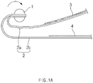
- a jelly-roll type electrode assembly is manufactured by winding a positive electrode 4, a separator 2, and a negative electrode 3 together around a winding core 1.
- separators 2a and 2b are input to the winding core 1 first, and then, the negative electrode 3 and the positive electrode 3 are input sequentially. That is, in the method for manufacturing the jelly-roll type electrode assembly, the winding core 1 is rotated in a state in which starting ends (ends in which the winding starts) of two sheets of separators 2a and 2b are overlapped on each other and fixed to the winding core 1. Then, the negative electrode 3 is input, and after a predetermined time is elapsed, the positive electrode 4 is input.
- the positive electrode is manufactured to have a length less than that of the negative electrode, and thus, the capacity of the manufactured electrode assembly is proportional to the length of the positive electrode 4, more specifically, to an area of the positive electrode 4 in which a positive electrode active material 4b is applied to a surface of a positive electrode collector 4a.
- the capacity of the manufactured electrode assembly is proportional to the length of the positive electrode 4, more specifically, to an area of the positive electrode 4 in which a positive electrode active material 4b is applied to a surface of a positive electrode collector 4a.
- FIG. 1B showing a state where the used electrode assembly is dissembled
- the separator 2 is thermally contracted in the starting end of the positive electrode 4, and accordingly, a short circuit may occur due to the contact between the positive electrode 4 and the negative electrode 3.
- the positive electrode 4 is input later than the negative electrode 3 when winding so as to prevent the internal short circuit.
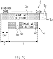
- the negative electrode 3 has a portion from the starting end to a certain point which is not coated with a negative electrode active material 3b, and the positive electrode 4 is input after a certain distance (a gap) from the point where the application of the negative electrode active material 3b starts (that is, the electrode assembly is manufactured such that there is a certain gap between a point where the application of the negative electrode active material starts in the negative electrode and a point where the application of the positive electrode active material starts in the positive electrode).
- a collector-exposed portion not coated with the negative electrode active material 3b in the negative electrode collector 3a is formed in each of the starting end (an end adjacent to the winding core) of the negative electrode 3 and the terminal end (an end in the outermost region).
- the terminal end collector-exposed portion of the negative electrode 3 has an area wider than that of the starting end collector-exposed portion, and the terminal end collector-exposed portion is bonded to a negative electrode tab 3c so as to be connected to the outside.
- the positive electrode 4 has a length less than the negative electrode 3, a collector-exposed portion not coated with the positive electrode active material 4b in the positive electrode collector 4a is formed in a predetermined position between both ends, and a structure is provided in which a positive electrode tab 4c is bonded to the collector-exposed portion.
- the electrode assembly in which the negative electrode 3 and the positive electrode 4 having the structures described above are wound may ensure safety in proportion to a distance difference D between the positive electrode 4 and the negative electrode 3.
- the positive electrode when the distance difference D is increased by shortening the positive electrode, the positive electrode does not contact the negative electrode even when the separator is contracted in a core part, and thus, the safety for the ignition is improved.
- the size of the positive electrode 4 is relatively reduced, causing a loss in capacity.
- the positive electrode does not face a negative electrode active material-coated portion of the negative electrode 3 (in particular, a negative electrode active material-coated portion in a gap region of FIG. 1C ), which is positioned in a region of the distance difference D at the winding central portion and coated with the negative electrode active material.
- the negative electrode active material is wasted without producing electricity.
- the negative electrode tab 3c is bonded to the center of a can for the safety.
- the negative electrode tab 3c has to be long so as to be connected to the center of the can when the negative electrode tab 3c is welded to a battery can.
- internal resistance direct current internal resistance (DCIR) and alternating current internal resistance (ACIR)
- the main object of the present invention is to provide an electrode assembly and a method for manufacturing same, in which a length of a positive electrode may be increased without deterioration in safety to maximize a capacity, and a welding distance of a negative electrode tab may be reduced to lower resistance.
- the present invention provides a method for manufacturing a jelly-roll type electrode assembly which is manufactured by winding a negative electrode, a separator, and a positive electrode around a winding core, the method comprising: a negative electrode rotating step (S1) of inputting a negative electrode and allowing the negative electrode to rotate such that the rotation around a winding core is performed from a starting end of the negative electrode; and a positive electrode inputting step (S2) of inputting a positive electrode after the rotation of the negative electrode starts and thereby allowing the positive electrode to rotate together with the negative electrode, wherein the negative electrode is manufactured by applying a negative electrode active material to a surface of the negative electrode collector, wherein a negative electrode collector-exposed portion, which is not coated with the negative electrode active material to expose the surface of the negative electrode collector, is formed in the starting end fixed to the winding core, and a negative electrode tab is bonded to the negative electrode collector-exposed portion.
- the negative electrode collector-exposed portion is formed in a terminal end of the negative electrode on the opposite side from the starting end, wherein, in the negative electrode rotating step (S1), the rotation starts from the negative electrode collector-exposed portion having a larger area among the negative electrode collector-exposed portions.
- An electrode assembly according to the present invention is a jelly roll-type electrode assembly manufactured by winding a negative electrode, a separator, and a positive electrode together from ends thereof, the electrode assembly comprising a negative electrode which is manufactured by applying a negative electrode active material to a surface of a negative electrode collector and which has, formed on one end thereof, a negative electrode collector-exposed portion that is not coated with the negative electrode active material to expose the surface of the negative electrode collector, wherein the negative electrode is wound together with a separator and a negative electrode such that the negative electrode collector-exposed portion is disposed in a central region where the winding starts, and a negative electrode tab is coupled to the negative electrode collector-exposed portion.
- the negative electrode collector-exposed portion is formed in each of both ends of the negative electrode, and the negative electrode collector-exposed portion having a larger area among the negative electrode collector-exposed portions is disposed in the central region.
- the negative electrode tab is coupled to the negative electrode collector-exposed portion having the larger area among the negative electrode collector-exposed portions, and the negative electrode collector-exposed portion is electrically connected to a negative electrode terminal (mounted to a can or a case in which the electrode assembly is accommodated) through the negative electrode tab.
- the electrode tab is coupled to the negative electrode collector-exposed portion while protruding in a width direction of the negative electrode.
- the positive electrode is shorter than the negative electrode so that the winding of the positive electrode starts later than the winding of the negative electrode when the winding of the negative electrode, the separator, and the positive electrode starts, wherein the winding of the positive electrode is completed earlier than the winding of the negative electrode.
- the winding is performed so that both ends of the positive electrode are spaced certain distances from the negative electrode collector-exposed portions, respectively, formed on both the ends of the negative electrode.
- the distances may be changed according to the specifications of the electrode assembly to be manufactured.
- the positive electrode is manufactured by applying a positive electrode active material to a surface of a positive electrode collector and has, formed therein, a positive electrode collector-exposed portion that is not coated with the positive electrode active material to expose the surface of the positive electrode collector, and the positive electrode collector-exposed portion is disposed between two regions of the positive electrode collector coated with the positive electrode active material.
- the positive electrode collector-exposed portion has an area less than that of the negative electrode collector-exposed portion having the larger area among the negative electrode collector-exposed portions and greater than that of the negative electrode collector-exposed portion having the smaller area among the negative electrode collector-exposed portions.
- the positive electrode collector-exposed portion is disposed closer to the negative electrode collector-exposed portion having the larger area among the negative electrode collector-exposed portions than the negative electrode collector-exposed portion having the smaller area.
- the electrode assembly having the structure described above is accommodated in a case to manufacture a secondary battery.
- the negative electrode tab is placed in the center of the electrode assembly, and thus, the negative electrode tab may decrease in length when welded to the can. Accordingly, the unnecessary increase in resistance may be reduced.
- the negative electrode collector-exposed portion positioned in the starting end (the end placed in the winding center) has the area greater than the area of the negative electrode collector-exposed portion positioned in the terminal end (the end placed in the outer portion of the electrode assembly), and thus, the gap between the point where the application of the negative electrode active material starts in the starting end and the point where the application of the positive electrode active material starts in the starting end may be reduced compared to the structure of the related art (that is, the length of the positive electrode may be increased compared to the structure of the related art). Therefore, the capacity of the electrode assembly may increase.
- the present invention relates to an electrode assembly, in which a capacity may be increased while internal resistance is reduced, and a method for manufacturing same.
- the present invention provides, as a first embodiment, a method for manufacturing a jelly-roll type electrode assembly which is manufactured by winding a negative electrode 30, a separator 20 (20a and 20b), and a positive electrode 40 around a winding core.
- FIG. 2 is a flowchart of steps applied in a method for manufacturing an electrode assembly according to the present invention.
- FIG. 3 is a view illustrating a state (a lower figure) in which a positive electrode and a negative electrode, which are input in an electrode assembly according to the present invention, are compared and a state (an upper figure) in which the negative electrode and the positive electrode are positioned in the electrode assembly.
- FIG. 3 illustrates that a space is provided inside while a negative electrode 30, a separator 20, and a positive electrode 40 rotate, but components are intentionally illustrated as being separated from each other because it is difficult to identify the components when the lines thereof in the drawing appear to stick together. That is, during the rotation, the negative electrode 30, the separator 20, and the positive electrode 40 are wound in a closely packed cylindrical shape while actually attached to each other.
- the present invention is manufactured such that two sheets of separators 20a and 20b are fixed to a winding core first as in the related art, and then, the negative electrode 30 is input first and the positive electrode 40 is input later (see the configuration of FIG. 1A ).
- a negative electrode tab 30c is bonded to a negative electrode collector-exposed portion, and the negative electrode collector-exposed portion to which the negative electrode tab 30c is bonded is positioned in a starting end (a left end of FIG. 3 as an end disposed adjacent to a winding core) of the negative electrode 30 so that the negative electrode tab 30c is positioned in a central region of the electrode assembly.
- the two sheets of separators 20a and 20b are fixed to the winding core first and wound therearound in the same manner as the related art. Then, the negative electrode 30 is input between the separators 20a and 20b or while being in contact with one of the separators 20a and 20b. A negative electrode rotating step (S1) is performed in which the negative electrode 30 rotates around the winding core together with the separators 20a and 20b.
- the rotation of the negative electrode 30 starts, and after a small time difference, the positive electrode 40 is inputted.
- the small time difference is a time difference enough to be able to form a distance difference D between the starting end (the left end in FIG. 3 ) of the negative electrode 30 and the starting end (the left end in FIG. 3 ) of the positive electrode 40 may be formed as illustrated in FIG. 3 .
- a positive electrode inputting step (S2) is performed in which, after the rotation of the negative electrode 30 starts, the positive electrode 40 is input to rotate together with the negative electrode 30. Then, when the winding core is rotated by a predetermined number of revolutions, the winding of the positive electrode 40, the negative electrode 30, and the separators 20 which have been input is completed.
- the negative electrode 30 according to the present invention is manufactured by applying a negative electrode active material 30b to a surface of a negative electrode collector 30a, and a negative electrode collector-exposed portion 31a, which is not coated with the negative electrode active material to expose the surface of the negative electrode collector 30a, is formed in the starting end fixed to the winding core.
- the negative electrode collector-exposed portion 31a is also formed in the terminal end of the negative electrode 30 as well as in the starting end.
- the negative electrode collector-exposed portion 31a formed in the starting end has an area greater than an area of the negative electrode collector-exposed portion 31b formed in the terminal end, and is bonded to the negative electrode tab 30c.
- the rotation starts from the negative electrode collector-exposed portion 31a having a larger area among the negative electrode collector-exposed portions 31a and 31b.
- the rotation starts from the negative electrode collector-exposed portion 31a having a larger area.
- the present invention having the structure described above may reduce a negative electrode active material-coated portion which is wasted in a region of a distance difference D between the positive electrode and the negative electrode at the winding central portion. That is, instead of applying the negative electrode active material to a region (a gap region of FIG. 1C ) that does not react, the negative electrode collector-exposed portion is formed in the region. Also, the negative electrode active material is additionally applied to a region of negative electrode collector-exposed portion formed in the winding terminal end of the negative electrode of the related art.
- an application length ( ⁇ of FIG. 3 ) of the negative electrode active material additionally applied to the winding terminal end the length of a portion of the terminal end of the positive electrode in which the positive electrode active material is applied may be increased by ⁇ . Electricity may be generated more by the extended reaction length ⁇ . Accordingly, the battery capacity may be further increased compared to the related art.
- the safety of the battery for the positive-negative electrode short circuit is determined by the positive-negative electrode distance difference D
- the distance difference of the positive electrode and the negative electrode is maintained at D so as to maintain the safety
- the length of the positive electrode may further extended to t+ ⁇ in the first embodiment of the present invention.
- the present invention provides, as a second embodiment, an electrode assembly which may be manufactured by the manufacturing method describe above.
- the electrode assembly according to the present invention is a jelly-roll type electrode assembly in which the negative electrode 30, the separator 20, the positive electrode 40 are stacked, wound from the center, and then manufactured in a cylindrical shape. Unlike the related art, the negative electrode tab 30c is disposed in or around the center of the cylindrical electrode assembly.
- the negative electrode 30 is manufactured by applying the negative electrode active material 30b to the surface of the negative electrode collector 30a, and the negative electrode collector-exposed portions 31a and 31b, which are not coated with the negative electrode active material 30b to expose the surface of the negative electrode collector 30a, are formed at both ends (that is, the starting end disposed close to the winding core, and the terminal end opposite thereto).
- the negative electrode collector-exposed portion 31a formed in the starting end has an area greater than an area of the negative electrode collector-exposed portion 31b formed in the terminal end, and the negative electrode tab 30c may be bonded to the negative electrode collector-exposed portion 31a formed in the starting end.
- the negative electrode tab 30c is bonded to the negative electrode collector-exposed portion 31a formed in the starting end of the negative electrode 30, and the negative electrode tab 30c is coupled to the negative electrode collector-exposed portion 31a while protruding in a width direction of the negative electrode 30.
- the negative electrode tab 30c is electrically connected to a negative electrode terminal (mounted to a can or a case in which the electrode assembly is accommodated).
- the positive electrode 40 is shorter than the negative electrode 30 so that, during the manufacturing process, the winding of the positive electrode 40, which is wound with the separator 20 therebetween, starts later than the winding of the negative electrode 30 and is completed earlier than the winding of the negative electrode 30. Also, the winding is performed so that both ends of the positive electrode 40 are spaced certain distances from the negative electrode collector-exposed portions 31a and 31b, respectively, formed on both the ends of the negative electrode 30.
- the positive electrode 40 has a gap ⁇ with respect to the starting end of the positive electrode 40 due to the existence of the negative electrode collector-exposed portion 31a positioned in the starting end of the negative electrode 30. Also, when the length of the positive electrode of the related art is t (see FIG. 1C ), the positive electrode extends by ⁇ corresponding to the extended length of the negative electrode active material and thus may have the length of t+ ⁇ .
- the negative electrode collector-exposed portion 31a having a larger area is positioned in the starting end of the negative electrode 30, and thus, the negative electrode active material remaining in the amount corresponding to the length of the negative electrode collector-exposed portion 31a may be applied to the terminal end of the negative electrode. Accordingly, the terminal end of the positive electrode 40 may be extended, and the length of the positive electrode may be maximized.
- a gap ⁇ between the negative electrode active material and the positive electrode active material in the starting end in the present invention may be smaller than the gap of the structure of the related art.
- the gap ⁇ between the negative electrode active material and the positive electrode active material represents a wasted region, and thus, the waste may be reduced in the present invention compared to the related art.
- a gap D is created for the safety (that is, the prevention of short circuit) by a predetermined distance (irrespective of the area of the negative electrode collector-exposed portion) between the starting end of the negative electrode 30 and the starting end of the positive electrode 40.
- the negative electrode active material is applied to a region closer to the starting end of the negative electrode.
- the negative electrode active material is applied from a region relatively away from the starting end of the negative electrode.
- the negative electrode active material is disposed closer to the starting end in the structure of FIG. 1C .
- the gap between the point where the application of the negative electrode active material starts and the point where the application of the positive electrode active material starts becomes larger than that of the structure in FIG. 3 . That is, the region having the gap is a region in which only the negative electrode active material is applied, and is a wasted region which is not involved in the charging and discharging of the electrode assembly.
- the distance of the wasted region is reduced to ⁇ in the embodiment, and according to the reduced size ⁇ , the length of the negative electrode active material applied to the terminal end of the negative electrode 30 is increased by ⁇ .
- the capacity may increase (That is, the gap of FIG. 1C may be the sum of ⁇ and ⁇ ) .
- the length of the negative electrode 30 does not change, a region to which the negative electrode active material is applied is relatively further extended in the terminal end of the negative electrode 30.
- the length of the positive electrode 40 may be extended by the length in which the application of the negative electrode active material is extended, as long as being shorter than the negative electrode 30. Accordingly, the capacity of the electrode assembly may increase.
- the size of ⁇ may be determined according to a manufacturing process. For example, the winding core having the sufficiently small size is used (condition 1), the application thickness of electrode active material has the uniformity over a certain level (condition 2), and a coating starting point difference is adjusted on both the surfaces of the electrode (condition 3). Under the above conditions, the size of ⁇ may have a value of 0.9 to 1.1 mm which is smaller than that of the structure of the related art.
- the capacity of battery may increase by 3.2 to 3.4%, and the energy density per volume may increase by 2 to 2.2%.
- the positive electrode 40 is manufactured by applying the positive electrode active material 40b to the surface of the positive electrode collector 40a, and a positive electrode collector-exposed portion 41, which are not coated with a positive electrode active material 40b to expose the surface of the positive electrode collector 40a, is formed.
- a positive electrode tab 40c is bonded to the positive electrode collector-exposed portion 41, and the positive electrode tab 40c is bonded while protruding in a direction opposite to the negative electrode tab 30c.
- the positive electrode collector-exposed portion 41 is disposed between two regions which are coated with the positive electrode active material 40b in the positive electrode collector 40a and separated from each other.
- the area and position of the positive electrode collector-exposed portion 41 is not limited within a specific range, but it is desirable that the positive electrode collector-exposed portion 41 has an area less than that of the negative electrode collector-exposed portion 31a having the larger area among the negative electrode collector-exposed portions 31a and 31b and greater than that of the negative electrode collector-exposed portion 31b having the smaller area among the negative electrode collector-exposed portions 31a and 31b.
- the positive electrode collector-exposed portion 41 is disposed closer to the negative electrode collector-exposed portion 31a having the larger area among the negative electrode collector-exposed portions 31a and 31b than the negative electrode collector-exposed portion 31b having the smaller area.
- the electrode assembly having the structure described above is accommodated in a case to manufacture a secondary battery.
- the negative electrode tab 30c is placed in the center of the electrode assembly, and thus, the negative electrode tab 30c may decrease in length when welded to the can. Accordingly, the unnecessary increase in resistance may be reduced.
- the negative electrode tab 30c is positioned close to the center of the electrode assembly in the structure of the present invention.
- welding may be performed directly on the bottom surface of the can to reduce the length, and accordingly, the increase in resistance may be reduced.
- the negative electrode collector-exposed portion 31a positioned in the starting end has the area greater than the area of the negative electrode collector-exposed portion 31b positioned in the terminal end (the end placed in the outer portion of the electrode assembly), and thus, the waste between the positive electrode 40 and the negative electrode 30 in the starting end may be reduced compared to the structure of the related art (that is, the length of the positive electrode may be increased compared to the structure of the related art). Therefore, the capacity of the electrode assembly may increase.
- FIG. 5 is a view illustrating graphs for comparing experimental results of an electrode assembly (Example) according to the present invention and electrode assemblies (Comparative examples 1 and 2) of the related art.
- the embodiment is the electrode assembly, having a structure as illustrated in FIG. 3 , in which the negative electrode collector-exposed portion 31a having the larger area is positioned in the center of the electrode assembly and the negative electrode tab 30c is disposed close to the center.
- Comparative example 1 is the electrode assembly, having the structure of the related art as illustrated in FIG. 1B , in which the negative electrode tab is disposed in an outer portion of the electrode assembly.
- Comparative example 2 is the electrode assembly having the same structure of the relate dart as Comparative example 1, but a gap between the positive electrode and the negative electrode is further extended (a structure in which the gap increases by 5 mm compared to Comparative example 1. That is, a structure in which the length of the positive electrode is further reduced in the structure of FIG.
- Comparative example 2 corresponds to FIG. 1C , and comparative example 2 has a structure in which the positive-negative electrode gap D is extended to a degree to prevent the short circuit). Also, in this experiment, the length of the positive electrode inside the electrode assembly of Comparative example 1 is the same as the length of the positive electrode inside the electrode assembly of Example. The length of the positive electrode in Comparative example 2 is reduced by the increase in gap between the positive electrode and the negative electrode.
- Each of the electrode assemblies is manufactured in a jelly-roll type and then inserted into a cylindrical can. Subsequently, an electrolyte is injected therein. Experiments were performed with cylindrical secondary batteries manufactured by a conventional method described above.
- the experiment condition is that each of the secondary batteries is placed in a closed chamber and heated at a rate of 5°C /min. Also, the temperature was maintained when reaching 130°C.
- Comparative example 1 Comparative example 2
- Comparative example 2 Comparative example 2
- the length of the positive electrode became shorter as the gap increased. Accordingly, the total capacity was decreased.
- the gap is increased without reducing the length of the present invention (without reduction in capacity) to obtain of improving the safety for ignition.
- Table 1 shows relative values of energy density and DCIR for Comparative example 1 and Example when the energy density of Comparative example 2 is B and DCIR is C.
- Comparative example 1 Comparative example 2
- Example 1 As shown in Table 1, the energy density of Example is equivalent to that of Comparative example 1, and a value of DCIR of Example was measured to be smaller than those of Comparative example 1 and Comparative example 2.
- Example of the present invention has the same length as the electrode assembly of Comparative example 1, and thus, the same energy density may be achieved.
- Example of the present invention may have the safety for ignition equivalent to Comparative example 2 (having an advantage of increasing the gap between the negative electrode and the positive electrode and thereby improving the safety for ignition, but having a disadvantage of decreasing the energy density).
- the negative electrode tab is moved to the center, and thus, the length thereof is reduced. Accordingly, there may be a secondary effect of reducing internal resistance.
Landscapes
- Chemical & Material Sciences (AREA)
- Chemical Kinetics & Catalysis (AREA)
- Electrochemistry (AREA)
- General Chemical & Material Sciences (AREA)
- Engineering & Computer Science (AREA)
- Manufacturing & Machinery (AREA)
- Secondary Cells (AREA)
- Composite Materials (AREA)
- Life Sciences & Earth Sciences (AREA)
- Sustainable Development (AREA)
- Sustainable Energy (AREA)
- Connection Of Batteries Or Terminals (AREA)
Abstract
Description
- The present application claims the benefit of the priority of
Korean Patent Application No. 10-2019-0124206, filed on October 07, 2019 - The present invention relates to an electrode assembly and a method for manufacturing same and, more specifically, to: an electrode assembly in which a gap between a point, where application of a positive electrode active material starts in a central region (in a starting end) of a jelly-roll type electrode assembly manufactured in a cylindrical shape, and a point, where application of a negative electrode active material starts, may be reduced thereby to increase capacity (capable of providing a space enabling increase in length of a distal end of a positive electrode); and a method for manufacturing same.
- Batteries for storing electric energy may be generally classified into a primary battery and a secondary battery. The primary battery is a disposable consumable battery, but on the other hand, the secondary battery is a rechargeable battery which is manufactured by using a material in which oxidation and reduction processes between electric current and substances are repeatable. That is, when the reduction reaction to the material is performed by the current, power is recharged. Also, when the oxidation reaction to the material is performed, the power is discharged. Such recharging and discharging may be performed repeatedly.
- Among various types of secondary batteries, a lithium secondary battery is generally manufactured by mounting, to a case, an electrode assembly in which a positive electrode (cathode), a separator, and a negative electrode (an anode) are stacked. The recharging and discharging of the lithium secondary battery are performed while lithium ions are intercalated into the negative electrode from lithium metal oxide of the positive electrode and deintercalated therefrom repeatedly.
- Also, a jelly-roll (winding) method, a stacking method, a stacking and folding method, and the like are well-known as methods for manufacturing the electrode assembly. In the jelly-roll (winding) method, a separator is stacked between the negative electrode and the positive electrode and then rolled. In the stacking method, a negative electrode and a positive electrode are cut into desired width and length and then the negative electrode, a separator, and the positive electrode are repeatedly stacked. In the stacking and folding method, unit cells are placed side by side on a folding separator and then folded from one side.
- Among the electrode assemblies, a jelly-roll type electrode assembly is manufactured by winding a
positive electrode 4, aseparator 2, and anegative electrode 3 together around a windingcore 1. - Herein, as illustrated in
FIG. 1A ,separators core 1 first, and then, thenegative electrode 3 and thepositive electrode 3 are input sequentially. That is, in the method for manufacturing the jelly-roll type electrode assembly, the windingcore 1 is rotated in a state in which starting ends (ends in which the winding starts) of two sheets ofseparators core 1. Then, thenegative electrode 3 is input, and after a predetermined time is elapsed, thepositive electrode 4 is input. - When the winding
core 1 is rotated by a predetermined number of revolutions in a state where thepositive electrode 4 is input, a configuration is obtained in which the starting ends of theseparators negative electrode 3 is positioned outward from the starting ends of theseparators positive electrode 4 is positioned outward from the starting end of thenegative electrode 3. - Here, the positive electrode is manufactured to have a length less than that of the negative electrode, and thus, the capacity of the manufactured electrode assembly is proportional to the length of the
positive electrode 4, more specifically, to an area of thepositive electrode 4 in which a positive electrodeactive material 4b is applied to a surface of apositive electrode collector 4a. Thus, it is advantageous in terms of capacity to apply the positive electrodeactive material 4b to the surface of thepositive electrode collector 4a as wide as possible. However, as illustrated inFIG. 1B showing a state where the used electrode assembly is dissembled, when heat is concentrated in the center of the electrode assembly, theseparator 2 is thermally contracted in the starting end of thepositive electrode 4, and accordingly, a short circuit may occur due to the contact between thepositive electrode 4 and thenegative electrode 3. - Thus, the
positive electrode 4 is input later than thenegative electrode 3 when winding so as to prevent the internal short circuit. Also, as illustrated inFIG. 1C comparing thenegative electrode 3 and thepositive electrode 4 that are input in a manufacturing method of the related art, thenegative electrode 3 has a portion from the starting end to a certain point which is not coated with a negative electrodeactive material 3b, and thepositive electrode 4 is input after a certain distance (a gap) from the point where the application of the negative electrodeactive material 3b starts (that is, the electrode assembly is manufactured such that there is a certain gap between a point where the application of the negative electrode active material starts in the negative electrode and a point where the application of the positive electrode active material starts in the positive electrode). Here, a collector-exposed portion not coated with the negative electrodeactive material 3b in thenegative electrode collector 3a is formed in each of the starting end (an end adjacent to the winding core) of thenegative electrode 3 and the terminal end (an end in the outermost region). The terminal end collector-exposed portion of thenegative electrode 3 has an area wider than that of the starting end collector-exposed portion, and the terminal end collector-exposed portion is bonded to anegative electrode tab 3c so as to be connected to the outside. Also, thepositive electrode 4 has a length less than thenegative electrode 3, a collector-exposed portion not coated with the positive electrodeactive material 4b in thepositive electrode collector 4a is formed in a predetermined position between both ends, and a structure is provided in which apositive electrode tab 4c is bonded to the collector-exposed portion. - The electrode assembly in which the
negative electrode 3 and thepositive electrode 4 having the structures described above are wound may ensure safety in proportion to a distance difference D between thepositive electrode 4 and thenegative electrode 3. - That is, when the distance difference D is increased by shortening the positive electrode, the positive electrode does not contact the negative electrode even when the separator is contracted in a core part, and thus, the safety for the ignition is improved. However, the size of the
positive electrode 4 is relatively reduced, causing a loss in capacity. Also, the positive electrode does not face a negative electrode active material-coated portion of the negative electrode 3 (in particular, a negative electrode active material-coated portion in a gap region ofFIG. 1C ), which is positioned in a region of the distance difference D at the winding central portion and coated with the negative electrode active material. Thus, there is a problem in that the negative electrode active material is wasted without producing electricity. - Also, the
negative electrode tab 3c is bonded to the center of a can for the safety. However, as thenegative electrode tab 3c is bonded to the terminal end collector-exposed portion of the negative electrode 3 (as the negative electrode tab is disposed in an outer portion of the electrode assembly), thenegative electrode tab 3c has to be long so as to be connected to the center of the can when thenegative electrode tab 3c is welded to a battery can. Thus, there is a problem in that internal resistance (direct current internal resistance (DCIR) and alternating current internal resistance (ACIR)) is unnecessarily increased. - Thus, the main object of the present invention is to provide an electrode assembly and a method for manufacturing same, in which a length of a positive electrode may be increased without deterioration in safety to maximize a capacity, and a welding distance of a negative electrode tab may be reduced to lower resistance.
- To achieve the above-described object, the present invention provides a method for manufacturing a jelly-roll type electrode assembly which is manufactured by winding a negative electrode, a separator, and a positive electrode around a winding core, the method comprising: a negative electrode rotating step (S1) of inputting a negative electrode and allowing the negative electrode to rotate such that the rotation around a winding core is performed from a starting end of the negative electrode; and a positive electrode inputting step (S2) of inputting a positive electrode after the rotation of the negative electrode starts and thereby allowing the positive electrode to rotate together with the negative electrode, wherein the negative electrode is manufactured by applying a negative electrode active material to a surface of the negative electrode collector, wherein a negative electrode collector-exposed portion, which is not coated with the negative electrode active material to expose the surface of the negative electrode collector, is formed in the starting end fixed to the winding core, and a negative electrode tab is bonded to the negative electrode collector-exposed portion.
- The negative electrode collector-exposed portion is formed in a terminal end of the negative electrode on the opposite side from the starting end, wherein, in the negative electrode rotating step (S1), the rotation starts from the negative electrode collector-exposed portion having a larger area among the negative electrode collector-exposed portions.
- Also, to achieve the above-described object, the present invention also provides an electrode assembly. An electrode assembly according to the present invention is a jelly roll-type electrode assembly manufactured by winding a negative electrode, a separator, and a positive electrode together from ends thereof, the electrode assembly comprising a negative electrode which is manufactured by applying a negative electrode active material to a surface of a negative electrode collector and which has, formed on one end thereof, a negative electrode collector-exposed portion that is not coated with the negative electrode active material to expose the surface of the negative electrode collector, wherein the negative electrode is wound together with a separator and a negative electrode such that the negative electrode collector-exposed portion is disposed in a central region where the winding starts, and a negative electrode tab is coupled to the negative electrode collector-exposed portion.
- The negative electrode collector-exposed portion is formed in each of both ends of the negative electrode, and the negative electrode collector-exposed portion having a larger area among the negative electrode collector-exposed portions is disposed in the central region.
- Also, the negative electrode tab is coupled to the negative electrode collector-exposed portion having the larger area among the negative electrode collector-exposed portions, and the negative electrode collector-exposed portion is electrically connected to a negative electrode terminal (mounted to a can or a case in which the electrode assembly is accommodated) through the negative electrode tab.
- The electrode tab is coupled to the negative electrode collector-exposed portion while protruding in a width direction of the negative electrode.
- Here, the positive electrode is shorter than the negative electrode so that the winding of the positive electrode starts later than the winding of the negative electrode when the winding of the negative electrode, the separator, and the positive electrode starts, wherein the winding of the positive electrode is completed earlier than the winding of the negative electrode.
- The winding is performed so that both ends of the positive electrode are spaced certain distances from the negative electrode collector-exposed portions, respectively, formed on both the ends of the negative electrode. Here, the distances may be changed according to the specifications of the electrode assembly to be manufactured.
- The positive electrode is manufactured by applying a positive electrode active material to a surface of a positive electrode collector and has, formed therein, a positive electrode collector-exposed portion that is not coated with the positive electrode active material to expose the surface of the positive electrode collector,
and the positive electrode collector-exposed portion is disposed between two regions of the positive electrode collector coated with the positive electrode active material. - It is desirable that the positive electrode collector-exposed portion has an area less than that of the negative electrode collector-exposed portion having the larger area among the negative electrode collector-exposed portions and greater than that of the negative electrode collector-exposed portion having the smaller area among the negative electrode collector-exposed portions.
- The positive electrode collector-exposed portion is disposed closer to the negative electrode collector-exposed portion having the larger area among the negative electrode collector-exposed portions than the negative electrode collector-exposed portion having the smaller area.
- The electrode assembly having the structure described above is accommodated in a case to manufacture a secondary battery.
- In the electrode assembly of the present invention having the structure described above, the negative electrode tab is placed in the center of the electrode assembly, and thus, the negative electrode tab may decrease in length when welded to the can. Accordingly, the unnecessary increase in resistance may be reduced.
- In particular, according to the present invention, the negative electrode collector-exposed portion positioned in the starting end (the end placed in the winding center) has the area greater than the area of the negative electrode collector-exposed portion positioned in the terminal end (the end placed in the outer portion of the electrode assembly), and thus, the gap between the point where the application of the negative electrode active material starts in the starting end and the point where the application of the positive electrode active material starts in the starting end may be reduced compared to the structure of the related art (that is, the length of the positive electrode may be increased compared to the structure of the related art). Therefore, the capacity of the electrode assembly may increase.
-
-
FIG. 1A is a view illustrating a state in which two sheets of separators are fixed to a winding core first, and then, a negative electrode and a positive electrode are sequentially input. -
FIG. 1B is a view illustrating a state (an upper figure) in which a used electrode assembly J/R is disassembled and unfolded and a state (a lower figure) in which the disassembled negative electrode and positive electrode are compared. -
FIG. 1C is a view comparing a negative electrode and a positive electrode which are input in a method for manufacturing a jelly-roll type electrode assembly of the related art. -
FIG. 2 is a flowchart of steps applied in a method for manufacturing an electrode assembly according to the present invention. -
FIG. 3 is a view illustrating a state (a lower figure) in which a positive electrode and a negative electrode, which are input in an electrode assembly according to the present invention, are compared and a state (an upper figure) in which the negative electrode and the positive electrode are positioned in the electrode assembly (FIG. 3 illustrates that a space is provided inside while the negative electrode, the separator, and the positive electrode rotate, but components are intentionally illustrated as being separated from each other because it is difficult to identify the components when the lines thereof in the drawing appear to stick together. That is, during the rotation, the negative electrode, the separator, and the positive electrode are wound in a closely packed cylindrical shape while actually attached to each other). -
FIG. 4 is a view illustrating a state (a left figure) in which a negative electrode tab and a positive electrode tab are positioned in an electrode assembly of the related art and a state (a right figure) in which a negative electrode tab and a positive electrode tab are positioned in an electrode assembly according to the present invention. -
FIG. 5 is a view illustrating graphs for comparing experimental results of an electrode assembly (Example) according to the present invention and electrode assemblies (Comparative examples 1 and 2) of the related art. - Hereinafter, the present invention will be described in detail with reference to the accompanying drawings so that the present invention can be easily carried out by a person skill in the art to which the present invention pertains. However, the present invention may be embodied in several different forms, and not be limited to the embodiments set forth herein.
- A part unrelated to the description will be omitted so as to clearly describe the present invention, and the same reference symbols are affixed to identical or similar elements throughout the specification.
- Also, terms or words used in this specification and claims should not be restrictively interpreted as ordinary meanings or dictionary-based meanings, but should be interpreted as meanings and concepts conforming to the scope of the present invention on the basis of the principle that an inventor can properly define the concept of a term to describe and explain his or her invention in the best ways.
- The present invention relates to an electrode assembly, in which a capacity may be increased while internal resistance is reduced, and a method for manufacturing same. Hereinafter, embodiments according to the present invention will be described in more detail with reference to the accompanying drawings.
- The present invention provides, as a first embodiment, a method for manufacturing a jelly-roll type electrode assembly which is manufactured by winding a
negative electrode 30, a separator 20 (20a and 20b), and apositive electrode 40 around a winding core. -
FIG. 2 is a flowchart of steps applied in a method for manufacturing an electrode assembly according to the present invention.FIG. 3 is a view illustrating a state (a lower figure) in which a positive electrode and a negative electrode, which are input in an electrode assembly according to the present invention, are compared and a state (an upper figure) in which the negative electrode and the positive electrode are positioned in the electrode assembly. For reference,FIG. 3 illustrates that a space is provided inside while anegative electrode 30, aseparator 20, and apositive electrode 40 rotate, but components are intentionally illustrated as being separated from each other because it is difficult to identify the components when the lines thereof in the drawing appear to stick together. That is, during the rotation, thenegative electrode 30, theseparator 20, and thepositive electrode 40 are wound in a closely packed cylindrical shape while actually attached to each other. - Referring to
FIGS. 2 and3 , the present invention is manufactured such that two sheets ofseparators negative electrode 30 is input first and thepositive electrode 40 is input later (see the configuration ofFIG. 1A ). In thenegative electrode 30 which is input in the present invention, anegative electrode tab 30c is bonded to a negative electrode collector-exposed portion, and the negative electrode collector-exposed portion to which thenegative electrode tab 30c is bonded is positioned in a starting end (a left end ofFIG. 3 as an end disposed adjacent to a winding core) of thenegative electrode 30 so that thenegative electrode tab 30c is positioned in a central region of the electrode assembly. - That is, in the manufacturing method of the present invention, the two sheets of
separators negative electrode 30 is input between theseparators separators negative electrode 30 rotates around the winding core together with theseparators - Also, the rotation of the
negative electrode 30 starts, and after a small time difference, thepositive electrode 40 is inputted. Here, the small time difference is a time difference enough to be able to form a distance difference D between the starting end (the left end inFIG. 3 ) of thenegative electrode 30 and the starting end (the left end inFIG. 3 ) of thepositive electrode 40 may be formed as illustrated inFIG. 3 . - A positive electrode inputting step (S2) is performed in which, after the rotation of the
negative electrode 30 starts, thepositive electrode 40 is input to rotate together with thenegative electrode 30. Then, when the winding core is rotated by a predetermined number of revolutions, the winding of thepositive electrode 40, thenegative electrode 30, and theseparators 20 which have been input is completed. - Also, the
negative electrode 30 according to the present invention is manufactured by applying a negative electrodeactive material 30b to a surface of anegative electrode collector 30a, and a negative electrode collector-exposedportion 31a, which is not coated with the negative electrode active material to expose the surface of thenegative electrode collector 30a, is formed in the starting end fixed to the winding core. - As illustrated in
FIG. 3 , the negative electrode collector-exposedportion 31a is also formed in the terminal end of thenegative electrode 30 as well as in the starting end. The negative electrode collector-exposedportion 31a formed in the starting end has an area greater than an area of the negative electrode collector-exposedportion 31b formed in the terminal end, and is bonded to thenegative electrode tab 30c. - That is, in the manufacturing method according to the embodiment, the rotation starts from the negative electrode collector-exposed
portion 31a having a larger area among the negative electrode collector-exposedportions portion 31a having a larger area. - The present invention having the structure described above may reduce a negative electrode active material-coated portion which is wasted in a region of a distance difference D between the positive electrode and the negative electrode at the winding central portion. That is, instead of applying the negative electrode active material to a region (a gap region of
FIG. 1C ) that does not react, the negative electrode collector-exposed portion is formed in the region. Also, the negative electrode active material is additionally applied to a region of negative electrode collector-exposed portion formed in the winding terminal end of the negative electrode of the related art. Thus, with respect to an application length (β ofFIG. 3 ) of the negative electrode active material additionally applied to the winding terminal end, the length of a portion of the terminal end of the positive electrode in which the positive electrode active material is applied may be increased by β. Electricity may be generated more by the extended reaction length β. Accordingly, the battery capacity may be further increased compared to the related art. - Here, since the safety of the battery for the positive-negative electrode short circuit is determined by the positive-negative electrode distance difference D, the distance difference of the positive electrode and the negative electrode is maintained at D so as to maintain the safety, and the length of the positive electrode may further extended to t+β in the first embodiment of the present invention.
- In addition, the present invention provides, as a second embodiment, an electrode assembly which may be manufactured by the manufacturing method describe above.
- The electrode assembly according to the present invention is a jelly-roll type electrode assembly in which the
negative electrode 30, theseparator 20, thepositive electrode 40 are stacked, wound from the center, and then manufactured in a cylindrical shape. Unlike the related art, thenegative electrode tab 30c is disposed in or around the center of the cylindrical electrode assembly. - In an embodiment, the
negative electrode 30 is manufactured by applying the negative electrodeactive material 30b to the surface of thenegative electrode collector 30a, and the negative electrode collector-exposedportions active material 30b to expose the surface of thenegative electrode collector 30a, are formed at both ends (that is, the starting end disposed close to the winding core, and the terminal end opposite thereto). - Here, the negative electrode collector-exposed
portion 31a formed in the starting end has an area greater than an area of the negative electrode collector-exposedportion 31b formed in the terminal end, and thenegative electrode tab 30c may be bonded to the negative electrode collector-exposedportion 31a formed in the starting end. Thenegative electrode tab 30c is bonded to the negative electrode collector-exposedportion 31a formed in the starting end of thenegative electrode 30, and thenegative electrode tab 30c is coupled to the negative electrode collector-exposedportion 31a while protruding in a width direction of thenegative electrode 30. Also, thenegative electrode tab 30c is electrically connected to a negative electrode terminal (mounted to a can or a case in which the electrode assembly is accommodated). - Here, the
positive electrode 40 is shorter than thenegative electrode 30 so that, during the manufacturing process, the winding of thepositive electrode 40, which is wound with theseparator 20 therebetween, starts later than the winding of thenegative electrode 30 and is completed earlier than the winding of thenegative electrode 30. Also, the winding is performed so that both ends of thepositive electrode 40 are spaced certain distances from the negative electrode collector-exposedportions negative electrode 30. - That is, as illustrated in
FIG. 3 , thepositive electrode 40 has a gap α with respect to the starting end of thepositive electrode 40 due to the existence of the negative electrode collector-exposedportion 31a positioned in the starting end of thenegative electrode 30. Also, when the length of the positive electrode of the related art is t (seeFIG. 1C ), the positive electrode extends by β corresponding to the extended length of the negative electrode active material and thus may have the length of t+β. - In the present invention, the negative electrode collector-exposed
portion 31a having a larger area is positioned in the starting end of thenegative electrode 30, and thus, the negative electrode active material remaining in the amount corresponding to the length of the negative electrode collector-exposedportion 31a may be applied to the terminal end of the negative electrode. Accordingly, the terminal end of thepositive electrode 40 may be extended, and the length of the positive electrode may be maximized. In this case, a gap α between the negative electrode active material and the positive electrode active material in the starting end in the present invention may be smaller than the gap of the structure of the related art. The gap α between the negative electrode active material and the positive electrode active material represents a wasted region, and thus, the waste may be reduced in the present invention compared to the related art. - As illustrated in
FIGS. 1C and3 , a gap D is created for the safety (that is, the prevention of short circuit) by a predetermined distance (irrespective of the area of the negative electrode collector-exposed portion) between the starting end of thenegative electrode 30 and the starting end of thepositive electrode 40. Here, in the structure of the related art inFIG. 1C , the negative electrode active material is applied to a region closer to the starting end of the negative electrode. On the other hand, in the structure of the embodiment inFIG. 3 , the negative electrode active material is applied from a region relatively away from the starting end of the negative electrode. - Thus, in a state where the gap D between the starting end of the
negative electrode 30 and the starting end of thepositive electrode 40 is fixed for the safety, the negative electrode active material is disposed closer to the starting end in the structure ofFIG. 1C . Thus, the gap between the point where the application of the negative electrode active material starts and the point where the application of the positive electrode active material starts becomes larger than that of the structure inFIG. 3 . That is, the region having the gap is a region in which only the negative electrode active material is applied, and is a wasted region which is not involved in the charging and discharging of the electrode assembly. However, the distance of the wasted region is reduced to α in the embodiment, and according to the reduced size α, the length of the negative electrode active material applied to the terminal end of thenegative electrode 30 is increased by β. Thus, the capacity may increase (That is, the gap ofFIG. 1C may be the sum of α and β) . Thus, in a state in which the length of thenegative electrode 30 does not change, a region to which the negative electrode active material is applied is relatively further extended in the terminal end of thenegative electrode 30. Thus, the length of thepositive electrode 40 may be extended by the length in which the application of the negative electrode active material is extended, as long as being shorter than thenegative electrode 30. Accordingly, the capacity of the electrode assembly may increase. - Here, the size of α may be determined according to a manufacturing process. For example, the winding core having the sufficiently small size is used (condition 1), the application thickness of electrode active material has the uniformity over a certain level (condition 2), and a coating starting point difference is adjusted on both the surfaces of the electrode (condition 3). Under the above conditions, the size of α may have a value of 0.9 to 1.1 mm which is smaller than that of the structure of the related art.
- When the size of α is reduced to 0.9 to 1.1 mm as described above, the capacity of battery may increase by 3.2 to 3.4%, and the energy density per volume may increase by 2 to 2.2%.
- Also, like the
negative electrode 30, thepositive electrode 40 is manufactured by applying the positive electrodeactive material 40b to the surface of thepositive electrode collector 40a, and a positive electrode collector-exposedportion 41, which are not coated with a positive electrodeactive material 40b to expose the surface of thepositive electrode collector 40a, is formed. Apositive electrode tab 40c is bonded to the positive electrode collector-exposedportion 41, and thepositive electrode tab 40c is bonded while protruding in a direction opposite to thenegative electrode tab 30c. - Unlike the negative electrode collector-exposed
portions portion 41 is disposed between two regions which are coated with the positive electrodeactive material 40b in thepositive electrode collector 40a and separated from each other. The area and position of the positive electrode collector-exposedportion 41 is not limited within a specific range, but it is desirable that the positive electrode collector-exposedportion 41 has an area less than that of the negative electrode collector-exposedportion 31a having the larger area among the negative electrode collector-exposedportions portion 31b having the smaller area among the negative electrode collector-exposedportions portion 41 is disposed closer to the negative electrode collector-exposedportion 31a having the larger area among the negative electrode collector-exposedportions portion 31b having the smaller area. - Also, the electrode assembly having the structure described above is accommodated in a case to manufacture a secondary battery.
- In the electrode assembly of the present invention having the structure described above, the
negative electrode tab 30c is placed in the center of the electrode assembly, and thus, thenegative electrode tab 30c may decrease in length when welded to the can. Accordingly, the unnecessary increase in resistance may be reduced. - As illustrated in
FIG. 4 showing a state (a left figure) in which thenegative electrode tab 3c and thepositive electrode tab 4c are positioned in an electrode assembly of the related art and a state (a right figure) in which thenegative electrode tab 30c and thepositive electrode tab 40c are positioned in the electrode assembly according to the present invention, thenegative electrode tab 30c is positioned close to the center of the electrode assembly in the structure of the present invention. Thus, welding may be performed directly on the bottom surface of the can to reduce the length, and accordingly, the increase in resistance may be reduced. - In particular, according to the present invention, the negative electrode collector-exposed
portion 31a positioned in the starting end (the end placed in the winding center) has the area greater than the area of the negative electrode collector-exposedportion 31b positioned in the terminal end (the end placed in the outer portion of the electrode assembly), and thus, the waste between thepositive electrode 40 and thenegative electrode 30 in the starting end may be reduced compared to the structure of the related art (that is, the length of the positive electrode may be increased compared to the structure of the related art). Therefore, the capacity of the electrode assembly may increase. -
FIG. 5 is a view illustrating graphs for comparing experimental results of an electrode assembly (Example) according to the present invention and electrode assemblies (Comparative examples 1 and 2) of the related art. - The embodiment is the electrode assembly, having a structure as illustrated in
FIG. 3 , in which the negative electrode collector-exposedportion 31a having the larger area is positioned in the center of the electrode assembly and thenegative electrode tab 30c is disposed close to the center. Also, Comparative example 1 is the electrode assembly, having the structure of the related art as illustrated inFIG. 1B , in which the negative electrode tab is disposed in an outer portion of the electrode assembly. Comparative example 2 is the electrode assembly having the same structure of the relate dart as Comparative example 1, but a gap between the positive electrode and the negative electrode is further extended (a structure in which the gap increases by 5 mm compared to Comparative example 1. That is, a structure in which the length of the positive electrode is further reduced in the structure ofFIG. 1B ) (Comparative example 2 corresponds toFIG. 1C , and comparative example 2 has a structure in which the positive-negative electrode gap D is extended to a degree to prevent the short circuit). Also, in this experiment, the length of the positive electrode inside the electrode assembly of Comparative example 1 is the same as the length of the positive electrode inside the electrode assembly of Example. The length of the positive electrode in Comparative example 2 is reduced by the increase in gap between the positive electrode and the negative electrode. - Each of the electrode assemblies is manufactured in a jelly-roll type and then inserted into a cylindrical can. Subsequently, an electrolyte is injected therein. Experiments were performed with cylindrical secondary batteries manufactured by a conventional method described above.
- The experiment condition is that each of the secondary batteries is placed in a closed chamber and heated at a rate of 5°C /min. Also, the temperature was maintained when reaching 130°C.
- As illustrated in
FIG. 5 , in the secondary battery of Comparative example 1, the temperature reached 130°C on about 22 to 23 minutes and was maintained for 10 minutes. Ignition occurred, and cell voltage became 0V. Also, in the secondary battery of Comparative example 2 and the secondary battery according to Example of the present invention, it may be found that the temperature reached 130°C and ignition did not occur for one hour or more. - That is, comparing Comparative example 1 and Comparative example 2, it may be found that the safety for ignition increases when the gap between the negative electrode and the positive electrode increases in the related art. However, in the structure of Comparative example 2, the length of the positive electrode became shorter as the gap increased. Accordingly, the total capacity was decreased. However, in the structure of Example of the present invention, it may be found that the gap is increased without reducing the length of the present invention (without reduction in capacity) to obtain of improving the safety for ignition.
- In addition, Table 1 below shows relative values of energy density and DCIR for Comparative example 1 and Example when the energy density of Comparative example 2 is B and DCIR is C.
[Table 1] Comparative example 1 Comparative example 2 Example Energy density (Wh/L) B+7 B B+7 DCIR (mohm) C C C-5 - As shown in Table 1, the energy density of Example is equivalent to that of Comparative example 1, and a value of DCIR of Example was measured to be smaller than those of Comparative example 1 and Comparative example 2.
- Consequently, from
FIG. 5 and Table 1, the electrode assembly according to Example of the present invention has the same length as the electrode assembly of Comparative example 1, and thus, the same energy density may be achieved. Also, Example of the present invention may have the safety for ignition equivalent to Comparative example 2 (having an advantage of increasing the gap between the negative electrode and the positive electrode and thereby improving the safety for ignition, but having a disadvantage of decreasing the energy density). Also, the negative electrode tab is moved to the center, and thus, the length thereof is reduced. Accordingly, there may be a secondary effect of reducing internal resistance. - Although the present invention is described by specific embodiments and drawings, the present invention is not limited thereto, and various changes and modifications may be made by a person skilled in the art to which the present invention pertains within the technical idea of the present invention and equivalent scope of the appended claims.
-
- 20:Separator
- 30:Negative electrode
- 40:Positive electrode
Claims (12)
- A jelly roll-type electrode assembly manufactured by winding a negative electrode, a separator, and a positive electrode together from ends thereof, the electrode assembly comprisinga negative electrode which is manufactured by applying a negative electrode active material to a surface of a negative electrode collector and which has, formed on one end thereof, a negative electrode collector-exposed portion that is not coated with the negative electrode active material to expose the surface of the negative electrode collector,wherein the negative electrode is wound together with a separator and a positive electrode such that the negative electrode collector-exposed portion is disposed in a central region where the winding starts, and a negative electrode tab is coupled to the negative electrode collector-exposed portion.
- The electrode assembly of claim 1, wherein the negative electrode collector-exposed portion is formed in each of both ends of the negative electrode, and
the negative electrode collector-exposed portion having a larger area among the negative electrode collector-exposed portions is disposed in the central region. - The electrode assembly of claim 2, wherein the negative electrode tab is coupled to the negative electrode collector-exposed portion having the larger area among the negative electrode collector-exposed portions, and
the negative electrode collector-exposed portion is electrically connected to a negative electrode terminal through the negative electrode tab. - The electrode assembly of claim 3, wherein the electrode tab is coupled to the negative electrode collector-exposed portion while protruding in a width direction of the negative electrode.
- The electrode assembly of claim 4, wherein the positive electrode is shorter than the negative electrode so that the winding of the positive electrode starts later than the winding of the negative electrode when the winding of the negative electrode, the separator, and the positive electrode starts,
wherein the winding of the positive electrode is completed earlier than the winding of the negative electrode. - The electrode assembly of claim 5, wherein the winding is performed so that both ends of the positive electrode are spaced certain distances from the negative electrode collector-exposed portions, respectively, formed on both the ends of the negative electrode.
- The electrode assembly of claim 2, wherein the positive electrode is manufactured by applying a positive electrode active material to a surface of a positive electrode collector and has, formed therein, a positive electrode collector-exposed portion that is not coated with the positive electrode active material to expose the surface of the positive electrode collector, and
the positive electrode collector-exposed portion is disposed between two regions of the positive electrode collector coated with the positive electrode active material. - The electrode assembly of claim 7, wherein the positive electrode collector-exposed portion has an area less than that of the negative electrode collector-exposed portion having the larger area among the negative electrode collector-exposed portions and greater than that of the negative electrode collector-exposed portion having the smaller area among the negative electrode collector-exposed portions.
- The electrode assembly of claim 7, wherein the positive electrode collector-exposed portion is disposed closer to the negative electrode collector-exposed portion having the larger area among the negative electrode collector-exposed portions than the negative electrode collector-exposed portion having the smaller area.
- A secondary battery in which the electrode assembly of any one of claims 1 to 9 is accommodated in a case.
- A method for manufacturing an electrode assembly which is manufactured by winding a negative electrode, a separator, and a positive electrode around a winding core, the method comprising:a negative electrode rotating step (S1) of inputting a negative electrode and allowing the negative electrode to rotate such that the rotation around a winding core is performed from a starting end of the negative electrode; anda positive electrode inputting step (S2) of inputting a positive electrode after the rotation of the negative electrode starts and thereby allowing the positive electrode to rotate together with the negative electrode,wherein the negative electrode is manufactured by applying a negative electrode active material to a surface of a negative electrode collector,wherein a negative electrode collector-exposed portion, which is not coated with the negative electrode active material to expose the surface of the negative electrode collector, is formed in the starting end fixed to the winding core, and a negative electrode tab is bonded to the negative electrode collector-exposed portion.
- The method of claim 11, wherein the negative electrode collector-exposed portion is formed in a terminal end of the negative electrode on the opposite side from the starting end,
wherein, in the negative electrode rotating step (S1), the rotation starts from the negative electrode collector-exposed portion having a larger area among the negative electrode collector-exposed portions.
Applications Claiming Priority (2)
| Application Number | Priority Date | Filing Date | Title |
|---|---|---|---|
| KR1020190124206A KR20210041454A (en) | 2019-10-07 | 2019-10-07 | Electrode assembly and manufacturing method thereof |
| PCT/KR2020/013632 WO2021071229A1 (en) | 2019-10-07 | 2020-10-07 | Electrode assembly and preparation method thereof |
Publications (2)
| Publication Number | Publication Date |
|---|---|
| EP4016683A1 true EP4016683A1 (en) | 2022-06-22 |
| EP4016683A4 EP4016683A4 (en) | 2023-01-11 |
Family
ID=75438289
Family Applications (1)
| Application Number | Title | Priority Date | Filing Date |
|---|---|---|---|
| EP20873712.2A Pending EP4016683A4 (en) | 2019-10-07 | 2020-10-07 | Electrode assembly and preparation method thereof |
Country Status (5)
| Country | Link |
|---|---|
| US (1) | US20220344697A1 (en) |
| EP (1) | EP4016683A4 (en) |
| KR (1) | KR20210041454A (en) |
| CN (1) | CN114365315B (en) |
| WO (1) | WO2021071229A1 (en) |
Family Cites Families (11)
| Publication number | Priority date | Publication date | Assignee | Title |
|---|---|---|---|---|
| JP3687251B2 (en) * | 1997-02-26 | 2005-08-24 | 宇部興産株式会社 | Non-aqueous secondary battery with wound electrode group and method for manufacturing the same |
| KR100948847B1 (en) * | 2003-01-16 | 2010-03-22 | 삼성에스디아이 주식회사 | Jelly-roll type electrode assembly and secondary battery applying the same |
| JP4798950B2 (en) * | 2004-01-23 | 2011-10-19 | 株式会社東芝 | Nonaqueous electrolyte secondary battery |
| KR100591435B1 (en) * | 2004-03-29 | 2006-06-22 | 삼성에스디아이 주식회사 | Can-type Lithium-ion Secondary Battery |
| JP4798967B2 (en) * | 2004-06-14 | 2011-10-19 | パナソニック株式会社 | Electrochemical element |
| JP2010186740A (en) * | 2009-01-16 | 2010-08-26 | Panasonic Corp | Electrode group for nonaqueous battery, its manufacturing method, cylindrical nonaqueous secondary battery and its manufacturing method |
| JP6058400B2 (en) * | 2011-02-03 | 2017-01-11 | 三洋電機株式会社 | Non-aqueous electrolyte secondary battery |
| KR101387424B1 (en) * | 2012-11-22 | 2014-04-25 | 주식회사 엘지화학 | Electrode assembly composed of electrode units with equal widths and different lengths, battery cell and device including the same |
| KR101678537B1 (en) * | 2013-07-31 | 2016-11-22 | 삼성에스디아이 주식회사 | Secondary battery |
| KR102234292B1 (en) * | 2014-04-09 | 2021-03-31 | 삼성에스디아이 주식회사 | Electrode assembly and secondary battery comprising the same |
| WO2017122251A1 (en) * | 2016-01-12 | 2017-07-20 | 三洋電機株式会社 | Non-aqueous electrolyte secondary battery |
-
2019
- 2019-10-07 KR KR1020190124206A patent/KR20210041454A/en not_active Application Discontinuation
-
2020
- 2020-10-07 US US17/764,388 patent/US20220344697A1/en active Pending
- 2020-10-07 EP EP20873712.2A patent/EP4016683A4/en active Pending
- 2020-10-07 CN CN202080063085.1A patent/CN114365315B/en active Active
- 2020-10-07 WO PCT/KR2020/013632 patent/WO2021071229A1/en unknown
Also Published As
| Publication number | Publication date |
|---|---|
| EP4016683A4 (en) | 2023-01-11 |
| US20220344697A1 (en) | 2022-10-27 |
| CN114365315B (en) | 2024-09-03 |
| CN114365315A (en) | 2022-04-15 |
| KR20210041454A (en) | 2021-04-15 |
| WO2021071229A1 (en) | 2021-04-15 |
Similar Documents
| Publication | Publication Date | Title |
|---|---|---|
| EP2130263B1 (en) | Jelly-roll having active material layer with different loading amount | |
| KR100387339B1 (en) | A method of manufacturing a battery including a non-circular spiral electrode body | |
| JPH11214027A (en) | Secondary battery compensating capacity ratio of positive electrode and negative electrode | |
| CN115803926A (en) | Energy storage cell and method for producing same | |
| WO1999017391A1 (en) | Lithium secondary battery and method for manufacturing the same | |
| KR100490548B1 (en) | Secondary battery with jelly-roll type electrode assembly | |
| JP3821434B2 (en) | Battery electrode group and non-aqueous electrolyte secondary battery using the same | |
| CN115552677A (en) | High energy density lithium ion battery | |
| EP3916882A1 (en) | Electrode assembly and manufacturing method therefor | |
| JP2000082484A (en) | Electrode roll for secondary battery | |
| KR101615712B1 (en) | Electrode assembly and secondary battery having the same | |
| EP4016683A1 (en) | Electrode assembly and preparation method thereof | |
| KR102619895B1 (en) | Secondary Battery | |
| KR20080084016A (en) | Electrode plate rolling device | |
| KR101835215B1 (en) | Cylinderical Secondary Battery And Method For Manufacturing The Same | |
| KR100322100B1 (en) | Sealed battery | |
| KR100307452B1 (en) | Electrode of secondary battery | |
| US11018395B2 (en) | Electrode assembly and manufacturing method thereof | |
| KR100529098B1 (en) | Secondary battery | |
| JPH05101815A (en) | Non-aqueous electrolyte battery | |
| US20240283104A1 (en) | Electrode Tab and Method for Cutting Electrode Tab | |
| KR20220073563A (en) | Secondary battery | |
| JPH09213361A (en) | Manufacture of spiral plate group | |
| US20230275329A1 (en) | Electrode assembly | |
| JP7125656B2 (en) | Non-aqueous electrolyte secondary battery |
Legal Events
| Date | Code | Title | Description |
|---|---|---|---|
| STAA | Information on the status of an ep patent application or granted ep patent |
Free format text: STATUS: THE INTERNATIONAL PUBLICATION HAS BEEN MADE |
|
| PUAI | Public reference made under article 153(3) epc to a published international application that has entered the european phase |
Free format text: ORIGINAL CODE: 0009012 |
|
| STAA | Information on the status of an ep patent application or granted ep patent |
Free format text: STATUS: REQUEST FOR EXAMINATION WAS MADE |
|
| 17P | Request for examination filed |
Effective date: 20220318 |
|
| AK | Designated contracting states |
Kind code of ref document: A1 Designated state(s): AL AT BE BG CH CY CZ DE DK EE ES FI FR GB GR HR HU IE IS IT LI LT LU LV MC MK MT NL NO PL PT RO RS SE SI SK SM TR |
|
| A4 | Supplementary search report drawn up and despatched |
Effective date: 20221212 |
|
| DAV | Request for validation of the european patent (deleted) | ||
| DAX | Request for extension of the european patent (deleted) | ||
| RIC1 | Information provided on ipc code assigned before grant |
Ipc: H01M 50/531 20210101ALI20221206BHEP Ipc: H01M 10/04 20060101AFI20221206BHEP |
|
| GRAP | Despatch of communication of intention to grant a patent |
Free format text: ORIGINAL CODE: EPIDOSNIGR1 |
|
| STAA | Information on the status of an ep patent application or granted ep patent |
Free format text: STATUS: GRANT OF PATENT IS INTENDED |
|
| RIC1 | Information provided on ipc code assigned before grant |
Ipc: H01M 50/531 20210101ALI20240812BHEP Ipc: H01M 10/04 20060101AFI20240812BHEP |
|
| GRAS | Grant fee paid |
Free format text: ORIGINAL CODE: EPIDOSNIGR3 |