EP4016578B1 - Diagnosevorrichtung für eine schaltung, entsprechendes schaltgerät und diagnoseverfahren - Google Patents
Diagnosevorrichtung für eine schaltung, entsprechendes schaltgerät und diagnoseverfahren Download PDFInfo
- Publication number
- EP4016578B1 EP4016578B1 EP20306629.5A EP20306629A EP4016578B1 EP 4016578 B1 EP4016578 B1 EP 4016578B1 EP 20306629 A EP20306629 A EP 20306629A EP 4016578 B1 EP4016578 B1 EP 4016578B1
- Authority
- EP
- European Patent Office
- Prior art keywords
- switching
- current
- temperature
- criterion
- value
- Prior art date
- Legal status (The legal status is an assumption and is not a legal conclusion. Google has not performed a legal analysis and makes no representation as to the accuracy of the status listed.)
- Active
Links
Images

Classifications
-
- H—ELECTRICITY
- H01—ELECTRIC ELEMENTS
- H01H—ELECTRIC SWITCHES; RELAYS; SELECTORS; EMERGENCY PROTECTIVE DEVICES
- H01H71/00—Details of the protective switches or relays covered by groups H01H73/00 - H01H83/00
- H01H71/10—Operating or release mechanisms
- H01H71/12—Automatic release mechanisms with or without manual release
- H01H71/40—Combined electrothermal and electromagnetic mechanisms
-
- H—ELECTRICITY
- H01—ELECTRIC ELEMENTS
- H01H—ELECTRIC SWITCHES; RELAYS; SELECTORS; EMERGENCY PROTECTIVE DEVICES
- H01H71/00—Details of the protective switches or relays covered by groups H01H73/00 - H01H83/00
- H01H71/04—Means for indicating condition of the switching device
-
- G—PHYSICS
- G01—MEASURING; TESTING
- G01R—MEASURING ELECTRIC VARIABLES; MEASURING MAGNETIC VARIABLES
- G01R31/00—Arrangements for testing electric properties; Arrangements for locating electric faults; Arrangements for electrical testing characterised by what is being tested not provided for elsewhere
-
- H—ELECTRICITY
- H01—ELECTRIC ELEMENTS
- H01H—ELECTRIC SWITCHES; RELAYS; SELECTORS; EMERGENCY PROTECTIVE DEVICES
- H01H47/00—Circuit arrangements not adapted to a particular application of the relay and designed to obtain desired operating characteristics or to provide energising current
- H01H47/02—Circuit arrangements not adapted to a particular application of the relay and designed to obtain desired operating characteristics or to provide energising current for modifying the operation of the relay
-
- H—ELECTRICITY
- H02—GENERATION; CONVERSION OR DISTRIBUTION OF ELECTRIC POWER
- H02H—EMERGENCY PROTECTIVE CIRCUIT ARRANGEMENTS
- H02H1/00—Details of emergency protective circuit arrangements
- H02H1/0007—Details of emergency protective circuit arrangements concerning the detecting means
-
- H—ELECTRICITY
- H02—GENERATION; CONVERSION OR DISTRIBUTION OF ELECTRIC POWER
- H02H—EMERGENCY PROTECTIVE CIRCUIT ARRANGEMENTS
- H02H5/00—Emergency protective circuit arrangements for automatic disconnection directly responsive to an undesired change from normal non-electric working conditions with or without subsequent reconnection
- H02H5/04—Emergency protective circuit arrangements for automatic disconnection directly responsive to an undesired change from normal non-electric working conditions with or without subsequent reconnection responsive to abnormal temperature
-
- H—ELECTRICITY
- H01—ELECTRIC ELEMENTS
- H01H—ELECTRIC SWITCHES; RELAYS; SELECTORS; EMERGENCY PROTECTIVE DEVICES
- H01H11/00—Apparatus or processes specially adapted for the manufacture of electric switches
- H01H11/0062—Testing or measuring non-electrical properties of switches, e.g. contact velocity
- H01H2011/0068—Testing or measuring non-electrical properties of switches, e.g. contact velocity measuring the temperature of the switch or parts thereof
-
- H—ELECTRICITY
- H01—ELECTRIC ELEMENTS
- H01H—ELECTRIC SWITCHES; RELAYS; SELECTORS; EMERGENCY PROTECTIVE DEVICES
- H01H71/00—Details of the protective switches or relays covered by groups H01H73/00 - H01H83/00
- H01H71/04—Means for indicating condition of the switching device
- H01H2071/042—Means for indicating condition of the switching device with different indications for different conditions, e.g. contact position, overload, short circuit or earth leakage
-
- H—ELECTRICITY
- H01—ELECTRIC ELEMENTS
- H01H—ELECTRIC SWITCHES; RELAYS; SELECTORS; EMERGENCY PROTECTIVE DEVICES
- H01H71/00—Details of the protective switches or relays covered by groups H01H73/00 - H01H83/00
- H01H71/10—Operating or release mechanisms
- H01H71/12—Automatic release mechanisms with or without manual release
- H01H71/14—Electrothermal mechanisms
- H01H71/16—Electrothermal mechanisms with bimetal element
- H01H71/162—Electrothermal mechanisms with bimetal element with compensation for ambient temperature
-
- H—ELECTRICITY
- H01—ELECTRIC ELEMENTS
- H01H—ELECTRIC SWITCHES; RELAYS; SELECTORS; EMERGENCY PROTECTIVE DEVICES
- H01H71/00—Details of the protective switches or relays covered by groups H01H73/00 - H01H83/00
- H01H71/10—Operating or release mechanisms
- H01H71/12—Automatic release mechanisms with or without manual release
- H01H71/46—Automatic release mechanisms with or without manual release having means for operating auxiliary contacts additional to the main contacts
-
- H—ELECTRICITY
- H01—ELECTRIC ELEMENTS
- H01H—ELECTRIC SWITCHES; RELAYS; SELECTORS; EMERGENCY PROTECTIVE DEVICES
- H01H9/00—Details of switching devices, not covered by groups H01H1/00 - H01H7/00
- H01H9/16—Indicators for switching condition, e.g. "on" or "off"
- H01H9/167—Circuits for remote indication
Definitions
- the present invention relates to a device for diagnosing a switch.
- the present invention also relates to a switch device comprising such a diagnostic device and a diagnostic method implemented by such a diagnostic device.
- switching devices or “circuit breakers”
- circuit breakers configured to cut off the current flowing when the intensity of this current is too high compared to a reference value, for example set to prevent heating of electrical conductors carrying the current.
- circuit breakers frequently used are of the so-called "magnetothermal" type. These circuit breakers use a switching system to open a switch and cut off the current, this switching system acting by two distinct and independent means.
- a first part of the switching system controls the opening of the switch when a magnetic field generated by the current (all or part of which flows, for example, in a coil) is greater than or equal to a threshold. For example, when the magnetic field is greater than or equal to the threshold, the force exerted by this magnetic field on a moving element exceeds another force, applied for example by a spring, and therefore causes the movement of this moving element to open the switch.
- a second part controls the opening of the switch when a temperature of the circuit breaker (caused by an overload) is greater than or equal to another threshold.
- a temperature of the circuit breaker (caused by an overload) is greater than or equal to another threshold.
- a bimetallic strip in contact with the conductor in which the current flows deforms, beyond a certain temperature, to cause the opening of the switch.
- circuit breaker switching systems typically include a handle to allow an operator or user to manually open or close the switch.
- the document US 2005/103613 A1 describes a device for diagnosing the cause of a cut-off caused by a magnetothermal circuit breaker.
- the diagnostic device is according to any one of claims 2 to 10.
- the switching device is according to any one of claims 12 and 13.
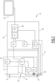
- a switching device 10 is shown in the figure 1 .
- the switching device 10 comprises a switching module 15 and a diagnostic device 20.
- the switching device 10 will be described below in the case where the switching device 10 comprises a single pole, but it will be apparent to those skilled in the art that the number of poles (i.e. of input-output pairs that the switching device 10 is each able to connect or disconnect) is likely to vary.
- the switching module 15 and the diagnostic device 20 are, for example, separate devices from each other and together form the switching device 10.
- the switching module 15 and the diagnostic device 20 are, as described below, each contained in a separate housing.
- the switching module 15 and the diagnostic device 20 are contained in the same single housing, and the elements making up the switching module 15 are not, for example, separated by a wall from the elements making up the diagnostic device 20.
- the switching module 15 is known per se.
- the switching module 15 comprises a first housing 22, at least one input 25, at least one output 30, a switching member 35 and a triggering system 40.
- the first housing 22 at least partially accommodates the or each input 25, the or each output 30, the switching member 35 and the triggering system 40.
- the first housing 22 is configured to electrically isolate the interior of the first housing 22 from the exterior of the first housing 22.
- the number of input(s) 25 and the number of output(s) 30 are each equal to the number of pole(s) of the switching device 10, here equal to one.
- the input 25 is electrically conductive and configured to be connected to a first device external to the switching device 10.
- the input 25 is, in particular, configured to receive an electric current from this external device.
- the input 25 comprises, for example, an input connection terminal intended to allow the connection of an electrical conductor or an electrical connector to the input terminal to electrically connect the first external device to the input 25.
- Input 25 comprises an electrical conductor or a plurality of electrical conductors connected together.
- the input 25 passes through, for example, the first housing 22 to allow its connection to the first external device.
- the input 25 is accommodated entirely in the first housing 22 but a portion of the input 25 intended to be connected to the first external device is arranged opposite an opening in the first housing 22 so as to allow the introduction of an electrical conductor into the first housing 22.
- the first external device can be of any nature, for example an electrical distribution network.
- the output 30 is configured to receive the electric current from the input 25 via the switching member 35.
- the output 30 is, furthermore, configured to transmit this current to a second device external to the switching device 10 to which the output 30 is configured to be connected.
- the output 30 comprises, for example, an output connection terminal intended to allow the connection of an electrical conductor or an electrical connector to the output terminal to electrically connect the second external device to the output 30.
- the output 30 passes through, for example, the first housing 22 to allow its connection to the second external device.
- the output 30 is accommodated entirely in the first housing 22 but a portion of the output 30 intended to be connected to the second external device is arranged opposite an opening in the first housing 22 so as to allow the introduction of an electrical conductor into the first housing 22.
- the second external device can be of any nature, for example a domestic electrical network, or even a device consuming electrical energy.
- the switching member 35 is, in a manner known per se, configured to switch between a first position and a second position.
- the switching member 35 When the switching member 35 is in the first position, the switching member 35 electrically connects the input 25 and the output 30.
- the switching member 35 When the switching member 35 is in the second position, the switching member 35 electrically isolates the input 25 and the output 30.
- the switching member 35 comprises in particular, in a manner known per se, an electrical conductor movable between a position in which the electrical conductor is simultaneously connected to the input 25 and to the output 30, and a position in which the electrical conductor is disconnected from at least one of the input 25 and the output 30.
- the switching member 35 also comprises a mechanism for moving the movable conductor between its two positions.
- the trigger system 40 is configured, in a manner known per se, to control a switching of the switching member 35 from the first position to the second position, and vice versa.
- the triggering system 40 comprises a triggering mechanism 45, a manual control member 50, a first thermal triggering subsystem 55 and a second magnetic triggering subsystem 60.
- the switching module 15 is often referred to as a “thermal-magnetic circuit breaker”, in particular when it forms a device separate from the diagnostic device 20.
- the switching device 10 which is referred to as a “thermal-magnetic circuit breaker”, as a whole.
- the trigger mechanism 45 is configured to act on the switching member to switch the switching member 35 between its two positions.
- the manual control member 50 is configured to be actuated by an operator so as to control the switching, by the trigger mechanism 45, of the switching member 35 from the first position to the second position, or vice versa.
- the manual control member 50 comprises, for example, a lever operable in rotation about an axis between two positions each corresponding to a position of the switching member 35.
- the manual control member 50 comprises at least one button configured to cause the switching member 35 to switch from one of its positions to the other when the operator presses the button.
- the manual control member 50 comprises two buttons, one causing a switch from the first to the second position and the other from the second to the first position following pressure from the operator.
- the first subsystem 55 is configured to control a switching of the switching member 35 from the first position to the second position when a first criterion is verified.
- the first criterion is that a first temperature of the switching module 15 is greater than or equal to a temperature threshold.
- the first subsystem 55 comprises, in a manner known per se, a bimetallic strip which is for example part of an electrical circuit connecting the switching member 35 to the output 30 and which is configured to be crossed by the current flowing from the input 25 to the output 30 when the switching member 35 is in the first position (or which is in contact with a conductor crossed by this current).
- the bimetallic strip is configured to deform according to its temperature and to act on the trigger mechanism 45 so as to switch the switching member 35 to its second position when the bimetallic strip temperature is greater than or equal to the temperature threshold.
- the first temperature is then the bimetallic strip temperature.
- the temperature threshold is chosen, in a manner known per se, as being such that, during normal operation of the switching device 10 under nominal conditions, the Joule effect causes the first temperature to increase to the temperature threshold when the current intensity is equal to or greater than a first current threshold for a predetermined duration.
- the predetermined duration depends, for example, on the operating conditions and the adjustment of the bimetal strip.
- the first current threshold is, for example, between 1.05 and 1.3 times a maximum acceptable current without tripping, at a reference temperature (or “caliber”) of the device 10, according to the IEC60898-1 standard. However, this first threshold is likely to vary.
- first subsystem controlling a switching when a first temperature reaches a temperature threshold
- systems not comprising a bimetallic strip are also conceivable, in particular systems not comprising a bimetallic strip.
- the second subsystem 60 is configured to control a switching of the switching member 35 from the first position to the second position when a second criterion is verified.
- the second criterion is that a magnetic field generated by the current flowing between input 25 and output 30 is greater than or equal to a field threshold.
- the switching module 15 comprises a coil in which the current (or a portion of the current if this coil is connected in parallel with another electrical conductor) flows.
- the magnetic field generated by the coil acts on a movable element of the second subsystem 60.
- the force exerted on the movable element by the magnetic field causes the latter to move, and this movement acts on the trigger mechanism 45 to control the switching of the switching member 35 to its second position.
- the field threshold is chosen such that the current generates a magnetic field equal to the field threshold when the current has an intensity value equal to a second current threshold.
- the second current threshold is in particular strictly greater than the first current threshold.
- the second current threshold is, for example, between 3 times and 10 times the rating.
- the diagnostic device 20 is configured to detect a switching of the switching member 35, to perform a diagnosis of the switching and to transmit diagnostic data to a device 62 external to the switching device 10.
- the device 62 is, for example, a computer or a server provided with a human-machine interface and capable of transmitting the data received to an operator, for example by displaying the data on a screen of the human-machine interface.
- the diagnostic data includes, for example, an identifier of the cause of the switching, for example “1”, “2” or “3”, or any indication allowing the device 62 to identify, among the three possible causes, the cause of the detected switching.
- the diagnostic data optionally includes additional information such as: a time instant of the switching, voltage or current values measured at the instant when the switching was commanded by the triggering system 40.
- the diagnostic device 20 includes a second housing 64, a switching sensor 65, a temperature sensor 70, a current sensor 75 and a controller 80.
- the second housing 64 at least partially accommodates the switching sensor 65, the temperature sensor 70, the current sensor 75 and the controller 80.
- the second housing 64 is, for example, configured to hold the switching sensor 65, the temperature sensor 70, the current sensor 75 and the controller 80 in position relative to each other.
- the second housing 64 is, for example, fixed to the first housing 22 by one or more hooks, and possibly by one or more electrical conductors.
- the second housing 64 and the first housing 22 are both fixed to the same support capable of holding them in position relative to each other.
- the switching sensor 65, the temperature sensor 70, the current sensor 75 and the controller 80 are accommodated in the housing 22, for example.
- the switching sensor 65 is configured to measure information relating to a switching of the switching member 35 and to signal to the controller 80 that a switching of the switching member 35 has taken place.
- the switching sensor 65 is, for example, mechanically connected to the switching member 35 and partially movable with it so as to actuate a module generating an electrical signal depending on the position of the switching member 35.
- the switching sensor 65 is configured to estimate the position in which the switching member 35 is by evaluating whether or not a current is flowing between the input 25 and the output 30.
- the switching sensor 65 detects by an electrical contact the position of the manual control member 50, which is itself integral with the position of the switching member 35.
- the temperature sensor 70 is configured to measure values of a second temperature of the switching device 10, for example using a thermocouple.
- the second temperature is, for example, measured inside the second housing 64.
- the second temperature is a temperature of the diagnostic device 20.
- the second temperature is a temperature of the switching module 15, for example of an electrical conductor of the switching module 15, in particular a temperature of the input 25 or of the output 30.
- the temperature sensor 70 comes into contact with at least a portion of the switching module 15, in particular of this electrical conductor, by passing through at least the second housing 64 and optionally through the first housing 22.
- the second temperature is, in particular, a temperature whose variation is correlated with the variation of the first temperature.
- the temperature sensor 70 is, for this, frequently positioned in the immediate vicinity of the bimetallic strip, for example one centimeter away or less.
- the current sensor 75 is configured to measure values of an intensity of the current passing through the switching module 15 from the input 25 to the output 30.
- the current sensor 75 is configured to measure current values periodically over time.
- the frequency of the measurements is, for example, greater than or equal to 1 kilohertz (kHz), for example equal to 20 kHz.
- the current sensor 75 comprises, for example, a sensor 85 configured to measure current values in analog form and an analog/digital converter 90 configured to convert the measured values into the form of a digital signal and to transmit the digital signal to the controller 80. It should be noted that the controller 80 and the analog/digital converter 90 are sometimes one and the same element performing these two functions.
- the current sensor 75 performs a frequency filtering of the measured values, for example a band-pass filtering around the expected frequency of the current, before transmitting the measured values to the controller 80.
- a saturation value is defined for the current sensor 75.
- the saturation value is a maximum intensity value, in absolute value, that the current sensor 75 is capable of measuring. For example, when the current has an intensity value greater than or equal, in absolute value, to the saturation value, the current sensor 75 generates a signal indicating that the intensity of the current is equal, in absolute value, to the saturation value.
- the saturation value is such that the current sensor 75 cannot differentiate, in absolute value, two currents having intensities greater in absolute value than the saturation value.
- the sensor 85 comprises, for example, a conductive torus surrounding a conductor of the switching module 15 (for example surrounding a conductor forming a portion of the input 25 or the output 30) and configured to generate an electric current as a function of a magnetic field generated by the current flowing in said conductor. Measuring the intensity of the electric current generated by the torus then makes it possible to estimate the value of the magnetic field and therefore the intensity of the current flowing in the conductor.
- the controller 80 is configured to detect a switching of the switching member 35 from at least one piece of information transmitted by the switching sensor 65.
- the controller 80 is further configured to receive the measured intensity and second temperature values and to diagnose a detected switching from the received intensity and second temperature values.
- the controller 80 comprises, for example, a processor 95 and a memory 100.
- the memory 100 contains software instructions configured to implement a method of diagnosing a switching of the switching device 10 when they are executed on the processor 95.
- the controller 80 is configured to communicate with the external device 62, for example by a wireless data link or by a wired network.
- the controller 80 is formed by a dedicated integrated circuit (in English, “Application-Specific Integrated Circuit”), by a set of programmable logic components, or even by any set of electronic components.
- FIG. 2 represents a flowchart of the steps of the diagnostic process implemented by this device 20.
- the diagnostic method comprises an initial step 200, a detection step 205, a first calculation step 210, a first estimation step 215, a second estimation step 220, a first comparison step 225, a first diagnostic step 230, a second calculation step 235, a determination step 240, a third calculation step 245, a second comparison step 250, a second diagnostic step 255 and a third diagnostic step 260.
- the switching member 35 is in the first position, and a current flows through the switching member 35 from the input 25 to the output 30.
- the current is, for example, an alternating current having a nominal period.
- the nominal period is, for example, equal to 50 Hertz (Hz), but is likely to vary from one installation to another.
- At least one second temperature value is measured by the temperature sensor 70 and transmitted to the controller 80, in particular to the second diagnostic module 110.
- values of the second temperature are measured periodically by the temperature sensor 70, with a time period of for example between 100 milliseconds (ms) and 10 seconds, although these values are likely to vary, in particular depending on the thermal capacity of the bimetallic strip.
- the current sensor 75 measures at least one value of the intensity of the current flowing between the input 25 and the output 30. For example, intensity values are measured by the current sensor 75 periodically. Alternatively, the values intensity are measured continuously by the current sensor 75, for example over a sliding time window.
- the initial step 200 is implemented until a switching from the first position to the second position of the switching member 35 takes place. This is represented by an arrow 265 on the figure 2 .
- the switching causes the switching sensor 65 to emit at least one signal indicating to the controller 80 that a switching has taken place.
- the controller 80 detects the switching following receipt of the signal emitted by the switching sensor 65.
- the controller 80 implements the detection step 205 following the detection of the switching.
- the controller 80 detects whether a saturation of the current sensor 75 has occurred during a first time range immediately preceding the switching.
- the first time range has a predetermined time duration and ends at the instant of switching.
- the first time range is defined as the time range over which a predetermined number of current values are measured, the most recent of the values measured over this first range being the last non-zero value measured (since switching cuts off the current).
- the first time range is, for example, a time range having a duration equal to a nominal half-period of the current and ending at the instant of switching.
- the first time range has a duration equal to a plurality of nominal half-periods, for example 5 half-periods.
- Saturation is, for example, detected if the current sensor 75 transmits to the controller 80 a plurality of successive intensity values having values equal to each other and equal, in absolute value, to the saturation value.
- the saturation value is an estimated value slightly lower than the actual saturation threshold, and saturation is then detected if the current sensor 75 transmits to the controller 80 a plurality of successive intensity values having values greater than or equal, in absolute value, to the saturation value.
- the first calculation step 210 is implemented. Otherwise, the first estimation step 215 is implemented.
- the controller 80 calculates at least one value of a time derivative of the measured intensity.
- the controller 80 calculates a value of a time derivative of the intensity at a time at which the intensity is equal to zero during the first time range, particularly at a time at which the intensity is equal to zero and the intensity value increases over time.
- the controller 80 calculates a value of the time derivative of the intensity corresponding to each instant at which an intensity value was measured during the first time range.
- the first calculation step 210 is followed by the second estimation step 220.
- an intensity value is estimated by the controller 80.
- the estimated value is, in particular, a maximum value of the intensity of the current during the first time range.
- the estimated intensity value is estimated from at least one calculated time derivative value, including from the time derivative value at the time at which the intensity is equal to zero.
- the estimated intensity value is estimated from the maximum derivative value (in absolute value) among the calculated derivative values.
- the estimated intensity value is, for example, estimated by considering that the current intensity is a sinusoidal function of time, and by calculating the estimated intensity value from knowledge of the value of the derivative at the instant when the intensity is equal to zero.
- the maximum derivative value is for example considered to be the value of the derivative at an instant when the current is zero and increases over time, since these statements are true when the current is a sinusoidal function of time.
- the second estimation step 220 is followed by the first comparison step 225.
- a maximum value of the intensity is estimated by the controller.
- the maximum value of the intensity is, for example, the highest value among the intensity values measured during the first time range.
- the maximum value of the intensity is estimated by interpolation or extrapolation from the measured intensity values, considering that the current is a sinusoidal function of time.
- the first estimation step 215 is followed by the first comparison step 225.
- the intensity value estimated during step 215 or 220 is compared to the second current threshold.
- the controller 80 determines that the switching was not caused because the second criterion was verified, and the second calculation step 235 is implemented.
- the controller 80 diagnoses the switching as a switching caused due to the second criterion. In other words, the controller 80 concludes that the switching was caused by the second trigger subsystem 60 because the magnetic field generated by the current was greater than or equal to the field threshold.
- the controller 80 In the first diagnostic step 230, the controller 80 generates and transmits to the remote device 62 a diagnostic message indicating that the switching was caused by the second subsystem 60.
- the diagnostic device 20 generates a signal intended for an operator indicating the cause of the switching, for example by displaying a message on a screen of the diagnostic device 20, or by displaying an indicator such as a colored mobile element visible from outside the diagnostic device 20 and indicating the cause of the switching.
- the controller 80 calculates an average value of the second temperature.
- the mean value is, for example, an arithmetic mean of second temperature values, that is, a mean calculated by summing a plurality of acquired second temperature values and dividing the sum by the number of values summed.
- the average value is, for example, calculated from second temperature values acquired successively during a second time range.
- the second time range has, for example, a predetermined time duration and is defined as the first time range having this duration and ending at the instant of switching.
- the second time range is defined as the time range over which a predetermined number of intensity values are measured, the most recent of the values measured during this time range being the second time range.
- second range being the last non-zero value measured (since switching cuts the current).
- the second time range for example, has a duration between 0 and 1 second.
- the second calculation step 235 is followed by the determination step 240.
- the controller 80 determines a third current threshold based on the calculated average value of the second temperature.
- the third threshold is determined based on a single second temperature value, measured for example at the instant of switching.
- the third current threshold is such that the Joule effect causes the first temperature to increase to the temperature threshold when the current intensity is equal to or greater than the third current threshold for a predetermined duration and when the second temperature is equal to the calculated average second temperature value.
- the third current threshold is calculated to take into account that, under actual operating conditions of the switching module 15, the switching module 15 is likely to be heated or cooled by external factors and that thus, the relationship between the current intensity and the first temperature is likely to be different from what was considered to set the temperature threshold.
- the temperature threshold has been set such that the first subsystem 55 triggers a switching of the switching member 35 when the current intensity is equal to the first threshold for a predetermined duration and the switching module 15 is placed alone in the middle of a volume of air at 15°C of 3 cubic meters (these values being examples likely to vary)
- the switching will take place for a lower intensity if the switching module 15 is heated beyond 15°C, for example by neighboring appliances or during the summer.
- the triggering will take place at a higher intensity.
- the third current threshold is, for example, determined from the average value of the second temperature and from a table, stored in the memory 100 and containing, for a plurality of stored values of the second temperature, respective values of the third threshold.
- the table contains, for each second temperature value stored in the table, a coefficient such that the third threshold is determined by multiplying the first threshold by the coefficient.
- Each coefficient value is strictly greater than zero.
- the corresponding coefficient value is strictly less than one.
- the corresponding coefficient value is strictly greater than one.
- the third threshold is, for example, calculated either by interpolation from the two third threshold values corresponding to said two successive values of the second temperature stored, or by interpolation from the two coefficient values corresponding to these successive values.
- the third threshold determined is the third threshold corresponding to the value of the second temperature stored closest to the average value.
- the table is, for example, a table determined experimentally by measuring an intensity value at which the first subsystem 55 triggers switching for each stored second temperature value.
- a difference between successive second temperature values stored in the table is, for example, between 1 degree Celsius (°C) and 10 °C, for example equal to 5 °C.
- the third threshold is calculated from a function, stored in the memory 100, and for example determined experimentally, linking the value of the third threshold to the second measured temperature.
- the function is, for example, an affine function defined by two coefficients stored in the memory 100.
- the third threshold is calculated from a single value of the second measured temperature and not from an average value.
- the third threshold is likely to be calculated or determined in different ways depending on one or more second temperature values.
- the third calculation step 245 is implemented immediately after the determination step 240.
- the average intensity value is, for example, calculated over the second time range.
- the mean intensity value is, for example, calculated from a plurality of successive RMS (Root Means Square) values, for example by an arithmetic mean of the RMS values.
- the number of successive RMS values included in the calculation of the average intensity value is, for example, between 0 and 10, for example equal to 5.
- the controller 80 periodically calculates, during the initial step 200, RMS values from, for example, N intensity values measured successively by the current sensor 75 (N being an integer strictly greater than 1).
- An RMS value is calculated, in a manner known per se, by calculating the square root of the mean of the squares of the measured values, for example the square root of a ratio between, in the numerator, a sum of squares of the N intensity values and, in the denominator, the number N.
- the number N is, for example, equal to the number of intensity samples acquired during a nominal period of the current.
- the number N is, in particular, between 303 and 444 when the nominal frequency of the current is between 45 Hz and 66 Hz and the sampling is carried out at 20 kHz.
- the third calculation step 245 is followed by the second comparison step 250.
- the controller 80 compares the calculated average intensity value to the third threshold.
- the second diagnostic step 255 is implemented. Otherwise, the third diagnostic step 260 is implemented.
- the controller 80 diagnoses the switching as being a switching caused due to the first criterion. In other words, the controller 80 concludes that the switching was caused by the first trigger subsystem 55 because the first temperature was greater than or equal to the temperature threshold.
- the controller 80 In the second diagnostic step 255, the controller 80 generates and transmits to the remote device 62 a diagnostic message indicating that the switching was caused by the first subsystem 55.
- the controller 80 diagnoses the switching as being a switching caused by an activation of the manual control member 50 by an operator.
- the controller 80 In the third diagnostic step 260, the controller 80 generates and transmits to the remote device 62 a diagnostic message indicating that the switching was caused by the manual control member 50.
- the diagnostic device 20 effectively differentiates between triggers caused by the subsystems 55 and 60 or by the manual control member 50, even when the switching device 10 is placed in an environment likely to heat or cool it relative to the nominal conditions for which the temperature threshold was chosen.
- the diagnostic device 20 attributes a triggering to an erroneous cause because the temperature of the switching device 10 is high or on the contrary low compared to the nominal conditions.
- the second temperature makes it possible to take into account the fact that the diagnostic device 10 is placed in temperature conditions different from those for which the first triggering subsystem 60 was initially calibrated.
- the information transmitted to an operator who has to intervene on the installation comprising the switching device 10 is therefore more precise, which makes the intervention more relevant, faster and, above all, more secure (since certain actions, relevant for one triggering cause, may prove dangerous for other causes).
- Calculating the third threshold based on one or more measured second temperature values makes it possible to accurately take into account the influence of the temperature of the diagnostic device 10 on the operation of the subsystem 55.
- the maximum current value is calculated from a derivative of the measured current values, the maximum value can be calculated accurately even when it exceeds the saturation value of the current sensor 75.
- Comparing the maximum current value to the second current threshold allows switching according to the second criterion to be detected quickly and easily.
- a switching caused by the manual control member 50 is easily and simply detected when it is determined that the first and second criteria do not apply, rather than providing for specific processing such as detecting the actuation of the member 50 using a specific sensor.
- the switching device 10 is particularly simplified since this specific sensor is not required.
- the diagnostic device 20 is particularly easy to manufacture since it is not necessary to provide access to the switching module 15 (for example) for the temperature sensor 70. Furthermore, the temperature sensor 70 is likely to be arranged inside a possible housing 64 and therefore to be protected, in particular when the device 20 and the module 15 are two separate devices provided with separate housings.
- the diagnosis is more accurate, since this second temperature more accurately reflects the first temperature. Erroneous diagnoses when, for example, the switching module 15 is not heated or cooled in a similar manner to the diagnostic device 10 are then avoided.
- a switching caused by the first criterion is likely to be diagnosed by directly comparing a second temperature value, for example the average second temperature value, to a corresponding temperature threshold.
- a second temperature value for example the average second temperature value
- the switching is a switching due to the first criterion if and only if the second temperature value is greater than or equal to the temperature threshold at which the first subsystem 55 triggers the switching.
- steps 235 to 255 are not implemented.
- the diagnostic device 20 is only configured to differentiate a triggering due to the second criterion from a manual triggering by the member 50.
Landscapes
- Physics & Mathematics (AREA)
- General Physics & Mathematics (AREA)
- Electromagnetism (AREA)
- Testing Of Short-Circuits, Discontinuities, Leakage, Or Incorrect Line Connections (AREA)
- Arrangements For Transmission Of Measured Signals (AREA)
- Emergency Protection Circuit Devices (AREA)
Claims (14)
- Diagnosevorrichtung (20), die für eine Schaltvorrichtung (10) bestimmt ist, umfassend ein Schaltmodul (15), das Schaltmodul (15) umfassend einen Eingang (25), einen Ausgang (30), ein Schaltglied (35) und ein Auslösesystem (40), wobei das Schaltglied (35) konfiguriert ist, um zwischen einer ersten Position, in der das Schaltglied (35) den Eingang (25) und den Ausgang (30) elektrisch verbindet, und einer zweiten Position, in der das Schaltglied (35) den Eingang (25) elektrisch von dem Ausgang (30) isoliert, zu schalten, wobei das Auslösesystem (40) dazu geeignet ist, um ein Schalten des Schaltglieds (35) von der ersten Position in die zweite Position zu steuern, das Auslösesystem (40) ein magnetothermisches Auslösesystem ist, das konfiguriert ist, um die Schaltung zu steuern, wenn ein Kriterium von einem ersten Kriterium oder einem zweiten Kriterium verifiziert wird, wobei das erste Kriterium die Tatsache ist, dass eine erste Temperatur eines Elements des Auslösesystems (40) größer als oder gleich wie ein Temperaturschwellenwert ist, das zweite Kriterium die Tatsache ist, dass ein Magnetfeld größer als oder gleich wie ein Feldschwellenwert ist, wobei das Magnetfeld durch einen elektrischen Strom erzeugt wird, der zwischen dem Eingang und dem Ausgang fließt, wenn das Schaltglied (35) in der ersten Position ist,die Diagnosevorrichtung (20) umfassend eine Steuereinheit (80), die konfiguriert ist, um ein Schalten des Schaltglieds (35) von der ersten Position in die zweite Position zu erfassen,die Diagnosevorrichtung (20) umfassendeinen Temperatursensor (70), der konfiguriert ist, um Werte einer zweiten Temperatur der Schaltvorrichtung (10) zu schätzen, und einen Stromsensor (75), der konfiguriert ist, um Werte einer Stromstärke des Stroms zu messen, wobei die Diagnosevorrichtung (20) dadurch gekennzeichnet ist, dass die Steuerung (80)konfiguriert ist, um nach der Erfassung einer Schaltungdas Schalten als ein Schalten aufgrund des ersten Kriteriums zu diagnostizieren, wenn mindestens ein Stromstärkewert größer als oder gleich wie ein sogenannter dritter Stromschwellenwert ist, wobei der dritte Stromschwellenwert von mindestens einem der geschätzten zweiten Temperaturwerte abhängt.
- Diagnosevorrichtung nach Anspruch 1, wobei die Steuereinheit (80) einen Speicher (100) umfasst und konfiguriert ist, um den dritten Stromschwellenwert anhand einer Tabelle, die in dem Speicher (100) gespeichert ist und Werte des dritten Stromschwellenwerts abhängig von der zweiten Temperatur enthält, oder anhand einer Funktion, die in dem Speicher gespeichert ist und Werte des dritten Stromschwellenwerts mit Werten der zweiten Temperatur verbindet, zu bestimmen.
- Diagnosevorrichtung nach einem der Ansprüche 1 oder 2, wobei die Steuerung (80) konfiguriert ist, um mindestens einen Stromstärkewert anhand mindestens eines Werts einer Ableitung der von dem Stromsensor gemessenen Stromstärke zu schätzen und um die Schaltung als eine Schaltung aufgrund des ersten Kriteriums basierend auf dem mindestens einen geschätzten Stromstärkewert zu diagnostizieren.
- Diagnosevorrichtung nach Anspruch 3, wobei die Steuerung (80) zu Folgendem konfiguriert ist:- Erfassen einer Sättigung des Stromsensors (75), Schätzen mindestens eines Stromstärkewerts anhand mindestens eines Wert einer Ableitung der gemessenen Stromstärke und Diagnostizieren der Schaltung basierend mindestens auf dem geschätzten Stromstärkewert, wenn eine Sättigung erfasst wird, und um- direkt die Schaltung abhängig von mindestens einem von dem Stromsensor (75) gemessenen Stromstärkewert bei nicht vorliegender Sättigung zu diagnostizieren.
- Diagnosevorrichtung nach Anspruch 3 oder 4, bei der der Strom ein Wechselstrom ist, der eine Zeitperiode aufweist, wobei jeder geschätzte Stromstärkewert anhand einer Ableitung der Stromstärke geschätzt wird, wobei die Ableitung eine maximale Ableitung der Stromstärke während einer Zeitperiode des Stroms ist, wobei jeder Stromstärkewert insbesondere unter der Annahme geschätzt wird, dass die Stromstärke eine sinusförmige Funktion der Zeit ist.
- Diagnosevorrichtung nach einem der Ansprüche 1 bis 5, wobei mindestens ein Wert der zweiten Temperatur ein Durchschnittswert der zweiten Temperatur während eines Zeitbereichs vor dem Schalten ist.
- Diagnosevorrichtung nach einem der Ansprüche 1 bis 6, ferner umfassend einen Stromsensor (75), der konfiguriert ist, um Werte einer Stromstärke des Stroms zu messen, wobei die Steuerung (80) ferner konfiguriert ist, um mindestens einen Stromstärkewert des Stroms mit einem zweiten Stromschwellenwert zu vergleichen und ein Schalten aufgrund des zweiten Kriteriums zu diagnostizieren, wenn der Stromstärkewert größer als oder gleich wie der zweite Stromschwellenwert ist.
- Diagnosevorrichtung nach Anspruch 7, wobei das Auslösesystem (40) ein Glied (50) umfasst, das konfiguriert ist, um die Umschaltung abhängig von einem Befehl eines Bedieners zu steuern, wobei die Steuerung (80) konfiguriert ist, um eine Schaltung als eine von einem Bediener gesteuerte Schaltung zu diagnostizieren, wenn die Steuerung die Schaltung nicht als eine Schaltung aufgrund des ersten Kriteriums oder des zweiten Kriteriums diagnostiziert.
- Diagnosevorrichtung nach einem der Ansprüche 1 bis 8, wobei die zweite Temperatur eine Temperatur der Diagnosevorrichtung (20) ist.
- Diagnosevorrichtung nach einem der Ansprüche 1 bis 8, wobei die zweite Temperatur eine Temperatur des Schaltmoduls (15) ist.
- Schaltvorrichtung (10), umfassend Schaltmodul (15), umfassend einen Eingang (25), einen Ausgang (30), ein Schaltglied (35) und ein Auslösesystem (40), wobei das Schaltglied (35) konfiguriert ist, um zwischen einer ersten Position, in der das Schaltglied (35) den Eingang (25) und den Ausgang (30) elektrisch verbindet, und einer zweiten Position, in der das Schaltglied (35) den Eingang (25) elektrisch von dem Ausgang (30) isoliert, zu schalten, wobei das Auslösesystem (40) dazu geeignet ist, um ein Schalten des Schaltglieds (35) von der ersten Position in die zweite Position zu steuern, das Auslösesystem (40) ein magnetothermisches Auslösesystem ist, das konfiguriert ist, um die Schaltung zu steuern, wenn ein Kriterium von einem ersten Kriterium oder einem zweiten Kriterium verifiziert wird, wobei das erste Kriterium die Tatsache ist, dass eine erste Temperatur eines Elements des Auslösesystems (40) größer als oder gleich wie ein Temperaturschwellenwert ist, das zweite Kriterium die Tatsache ist, dass ein Magnetfeld größer als oder gleich wie ein Feldschwellenwert ist, wobei das Magnetfeld durch einen elektrischen Strom erzeugt wird, der zwischen dem Eingang und dem Ausgang fließt, wenn das Schaltglied (35) in der ersten Position ist, die Schaltvorrichtung (10) umfassend eine Diagnosevorrichtung (20) nach einem der Ansprüche 1 bis 10.
- Schaltvorrichtung nach Anspruch 11, wobei die Diagnosevorrichtung (20) ein erstes Gehäuse (64) umfasst, das die Steuerung (80) enthält, das Schaltmodul (15) umfassend ein zweites Gehäuse (22), das das Schaltglied (35) und das Auslösesystem (40) enthält, wobei das erste Gehäuse (64) von dem zweiten Gehäuse (22) getrennt ist und konfiguriert ist, um an dem zweiten Gehäuse (22) befestigt zu werden.
- Schaltvorrichtung nach Anspruch 11, umfassend ein einziges Hauptgehäuse, das die Diagnosevorrichtung (20) und das Schaltmodul (15) enthält.
- Diagnoseverfahren einer Schaltung einer Schaltvorrichtung (10), umfassend ein Schaltmodul (15), umfassend einen Eingang (25), einen Ausgang (30), ein Schaltglied (35) und ein Auslösesystem (40), wobei das Schaltglied (35) konfiguriert ist, um zwischen einer ersten Position, in der das Schaltglied (35) den Eingang (25) und den Ausgang (30) elektrisch verbindet, und einer zweiten Position, in der das Schaltglied (35) den Eingang (25) elektrisch von dem Ausgang (30) isoliert, zu schalten, wobei das Auslösesystem (40) dazu geeignet ist, um ein Schalten des Schaltglieds (35) von der ersten Position in die zweite Position zu steuern, das Auslösesystem (40) ein magnetothermisches Auslösesystem ist, das konfiguriert ist, um die Schaltung zu steuern, wenn ein Kriterium von einem ersten Kriterium oder einem zweiten Kriterium verifiziert wird, wobei das erste Kriterium die Tatsache ist, dass eine erste Temperatur eines Elements des Auslösesystems (40) größer als oder gleich wie ein Temperaturschwellenwert ist, das zweite Kriterium die Tatsache ist, dass ein Magnetfeld größer als oder gleich wie ein Feldschwellenwert ist, wobei das Magnetfeld durch einen elektrischen Strom erzeugt wird, der zwischen dem Eingang und dem Ausgang fließt, wenn das Schaltglied (35) in der ersten Position ist,wobei das Verfahren durch eine Diagnosevorrichtung (20) implementiert wird, umfassend eine Steuerung (80), einen Stromsensor (75) und einen Temperatursensor (70),das Verfahren umfassend die folgenden Schritte:- Messen (200), durch den Temperatursensor (70), von mindestens einem Wert einer zweiten Temperatur der Schaltvorrichtung,- Erfassen, durch die Steuereinheit (80), eines Schaltens des Schaltelements (35) von der ersten Position in die zweite Position, und- Diagnostizieren (255), durch die Steuereinheit (80), der Schaltung als eine Schaltung aufgrund des ersten Kriteriums, wenn mindestens ein Stromstärkewert größer als oder gleich wie ein so genannter dritter Stromschwellenwert ist, wobei der dritte Stromschwellenwert von mindestens einem der geschätzten zweiten Temperaturwerte abhängt.
Priority Applications (2)
| Application Number | Priority Date | Filing Date | Title |
|---|---|---|---|
| EP20306629.5A EP4016578B1 (de) | 2020-12-21 | 2020-12-21 | Diagnosevorrichtung für eine schaltung, entsprechendes schaltgerät und diagnoseverfahren |
| CN202111528060.7A CN114649172A (zh) | 2020-12-21 | 2021-12-14 | 切换诊断设备以及相关联的切换设备和诊断方法 |
Applications Claiming Priority (1)
| Application Number | Priority Date | Filing Date | Title |
|---|---|---|---|
| EP20306629.5A EP4016578B1 (de) | 2020-12-21 | 2020-12-21 | Diagnosevorrichtung für eine schaltung, entsprechendes schaltgerät und diagnoseverfahren |
Publications (3)
| Publication Number | Publication Date |
|---|---|
| EP4016578A1 EP4016578A1 (de) | 2022-06-22 |
| EP4016578C0 EP4016578C0 (de) | 2025-01-29 |
| EP4016578B1 true EP4016578B1 (de) | 2025-01-29 |
Family
ID=74184381
Family Applications (1)
| Application Number | Title | Priority Date | Filing Date |
|---|---|---|---|
| EP20306629.5A Active EP4016578B1 (de) | 2020-12-21 | 2020-12-21 | Diagnosevorrichtung für eine schaltung, entsprechendes schaltgerät und diagnoseverfahren |
Country Status (2)
| Country | Link |
|---|---|
| EP (1) | EP4016578B1 (de) |
| CN (1) | CN114649172A (de) |
Families Citing this family (2)
| Publication number | Priority date | Publication date | Assignee | Title |
|---|---|---|---|---|
| DE102023209394A1 (de) * | 2023-09-26 | 2025-03-27 | Siemens Aktiengesellschaft | Verfahren zur Bewertung eines Schaltereignisses |
| DE102023209395A1 (de) * | 2023-09-26 | 2025-03-27 | Siemens Aktiengesellschaft | Verfahren zur Bestimmung einer thermischen Lebensdauer |
Family Cites Families (2)
| Publication number | Priority date | Publication date | Assignee | Title |
|---|---|---|---|---|
| US7030769B2 (en) * | 2003-11-13 | 2006-04-18 | Eaton Corporation | Monitor providing cause of trip indication and circuit breaker incorporating the same |
| FR3010584B1 (fr) * | 2013-09-12 | 2015-10-02 | Schneider Electric Ind Sas | Appareil auxiliaire pour disjoncteur electrique, systeme electrique comportant un disjoncteur et un tel appareil auxiliaire et procede de determination d'une cause de l'ouverture du disjoncteur a l'aide d'un tel appareil auxiliaire |
-
2020
- 2020-12-21 EP EP20306629.5A patent/EP4016578B1/de active Active
-
2021
- 2021-12-14 CN CN202111528060.7A patent/CN114649172A/zh active Pending
Also Published As
| Publication number | Publication date |
|---|---|
| EP4016578A1 (de) | 2022-06-22 |
| EP4016578C0 (de) | 2025-01-29 |
| CN114649172A (zh) | 2022-06-21 |
Similar Documents
| Publication | Publication Date | Title |
|---|---|---|
| EP2849196B1 (de) | Verfahren zur Erkennung der Ursache eines Spannungsverlusts vor einem Trennschalter, Hilfsgerät für Trennschalter sowie elektrisches System, das einen solchen Trennschalter und ein solches Hilfsgerät umfasst | |
| EP1466336B1 (de) | Verfahren zum feststellen von kontaktverschleiss eines elektrischen gerätes | |
| EP0258090B1 (de) | Statischer Auslöser für Leistungsschalter mit elektronischer Kontaktabnutzungsanzeige | |
| EP2849195B1 (de) | Zusatzvorrichung für elektrischen Schutzschalter, elektrisches System mit einem Schutzschalter und dieser Zusatzvorrichtung und Verfahren zur Bestimmung des Grunds der Öffnung des Schutzshalters dank dieser Zusatzvorrichtung | |
| EP4016578B1 (de) | Diagnosevorrichtung für eine schaltung, entsprechendes schaltgerät und diagnoseverfahren | |
| WO2019110711A1 (fr) | Procede de detection de l'etat d'un appareil de protection electrique dans une installation electrique et dispositif de detection mettant en oeuvre ledit procede | |
| EP2927928B1 (de) | Verfahren zur bestimmung einer überhitzung mindestens einer verbindungsklemme einer elektrischen vorrichtung, entsprechendes hilfsgerät und elektrisches system, das eine solche elektrische vorrichtung und ein solches hilfsgerät umfasst | |
| CN111856262A (zh) | 一种gis刀闸检测方法、装置、系统、设备及存储介质 | |
| EP2648010A1 (de) | Verfahren zur Verwaltung von Alarmsignalen in Abhängigkeit von den Fehlerströmen in einer elektrischen Anlage, und Vorrichtung zur Umsetzung dieses Verfahrens | |
| EP2682972B1 (de) | Vorrichtung zur Erkennung des offenen oder geschlossenen Zustands eines Schalters, und Schutz-Relaisüberwachungsvorrichtung des entsprechenden Transformators | |
| FR2974684A1 (fr) | Systeme de protection et de supervision d'un circuit de distribution d'energie electrique a courant continu | |
| EP3790034A1 (de) | Elektronisches hilfsschutzmodul und entsprechende schutzschaltervorrichtung | |
| EP0866485B1 (de) | Schutzvorrichtung für einen elektrischen Motor mit Fehlersignalisierung vor Aktivierung | |
| EP4343289A1 (de) | Verfahren und system zur bestimmung einer auslösedomäne einer elektrischen schaltvorrichtung | |
| EP3977577A1 (de) | Schutzvorrichtung für stromleitung (l) zum erkennen eines leckfehlers, kurzschlusses, fehlers, überstromfehlers und lichtbogenfehlers | |
| EP4075471A1 (de) | Elektrisches hilfsschutzmodul, elektrisches schutzgerät mit einem solchen modul und entsprechendes betriebsverfahren | |
| EP3511970B1 (de) | Elektrischer schalter mit einem detektor welcher informationen über die auslösung des schalters in einen bus einspeist | |
| EP4651327A1 (de) | Verfahren zur schätzung einer auslöseintensität eines schutzschalters, system, anordnung und computerprogramm dafür | |
| EP4492598A1 (de) | Verfahren zur überprüfung der eignung für restströme von differentialschutzschaltern | |
| EP3764496A1 (de) | Verfahren, das mithilfe eines schutzgeräts in der lage ist, mindestens eine fehlerinformation in bezug auf mindestens einen erfassten fehler in einer stromleitung anzuzeigen, ein solches schutzgerät und elektrische anlage, die mindestens ein solches schutzgerät umfasst | |
| WO2018149998A1 (fr) | Disjoncteur | |
| FR2994349A1 (fr) | Systeme de protection d'une pluralite de departs electriques contre des courts-circuits, et installation electrique comprenant un tel systeme de protection | |
| EP3809440A1 (de) | Schutzgerät einer elektrischen anlage mit wechselstrom | |
| FR2774173A1 (fr) | Procede de test d'un disjoncteur electrique differentiel et dispositif pour la mise en oeuvre d'un tel procede | |
| FR2989823A1 (fr) | Disjoncteur de branchement d'abonne au reseau de distribution d'energie electrique basse tension |
Legal Events
| Date | Code | Title | Description |
|---|---|---|---|
| PUAI | Public reference made under article 153(3) epc to a published international application that has entered the european phase |
Free format text: ORIGINAL CODE: 0009012 |
|
| STAA | Information on the status of an ep patent application or granted ep patent |
Free format text: STATUS: THE APPLICATION HAS BEEN PUBLISHED |
|
| AK | Designated contracting states |
Kind code of ref document: A1 Designated state(s): AL AT BE BG CH CY CZ DE DK EE ES FI FR GB GR HR HU IE IS IT LI LT LU LV MC MK MT NL NO PL PT RO RS SE SI SK SM TR |
|
| STAA | Information on the status of an ep patent application or granted ep patent |
Free format text: STATUS: REQUEST FOR EXAMINATION WAS MADE |
|
| 17P | Request for examination filed |
Effective date: 20221124 |
|
| RBV | Designated contracting states (corrected) |
Designated state(s): AL AT BE BG CH CY CZ DE DK EE ES FI FR GB GR HR HU IE IS IT LI LT LU LV MC MK MT NL NO PL PT RO RS SE SI SK SM TR |
|
| GRAP | Despatch of communication of intention to grant a patent |
Free format text: ORIGINAL CODE: EPIDOSNIGR1 |
|
| STAA | Information on the status of an ep patent application or granted ep patent |
Free format text: STATUS: GRANT OF PATENT IS INTENDED |
|
| INTG | Intention to grant announced |
Effective date: 20240904 |
|
| RIN1 | Information on inventor provided before grant (corrected) |
Inventor name: GRAND, SEBASTIEN Inventor name: BERNARD, JEAN-BAPTISTE |
|
| GRAS | Grant fee paid |
Free format text: ORIGINAL CODE: EPIDOSNIGR3 |
|
| GRAA | (expected) grant |
Free format text: ORIGINAL CODE: 0009210 |
|
| STAA | Information on the status of an ep patent application or granted ep patent |
Free format text: STATUS: THE PATENT HAS BEEN GRANTED |
|
| AK | Designated contracting states |
Kind code of ref document: B1 Designated state(s): AL AT BE BG CH CY CZ DE DK EE ES FI FR GB GR HR HU IE IS IT LI LT LU LV MC MK MT NL NO PL PT RO RS SE SI SK SM TR |
|
| REG | Reference to a national code |
Ref country code: GB Ref legal event code: FG4D Free format text: NOT ENGLISH |
|
| REG | Reference to a national code |
Ref country code: CH Ref legal event code: EP |
|
| REG | Reference to a national code |
Ref country code: DE Ref legal event code: R096 Ref document number: 602020045475 Country of ref document: DE |
|
| REG | Reference to a national code |
Ref country code: IE Ref legal event code: FG4D Free format text: LANGUAGE OF EP DOCUMENT: FRENCH |
|
| U01 | Request for unitary effect filed |
Effective date: 20250221 |
|
| U07 | Unitary effect registered |
Designated state(s): AT BE BG DE DK EE FI FR IT LT LU LV MT NL PT RO SE SI Effective date: 20250228 |
|
| PG25 | Lapsed in a contracting state [announced via postgrant information from national office to epo] |
Ref country code: RS Free format text: LAPSE BECAUSE OF FAILURE TO SUBMIT A TRANSLATION OF THE DESCRIPTION OR TO PAY THE FEE WITHIN THE PRESCRIBED TIME-LIMIT Effective date: 20250429 |
|
| PG25 | Lapsed in a contracting state [announced via postgrant information from national office to epo] |
Ref country code: PL Free format text: LAPSE BECAUSE OF FAILURE TO SUBMIT A TRANSLATION OF THE DESCRIPTION OR TO PAY THE FEE WITHIN THE PRESCRIBED TIME-LIMIT Effective date: 20250129 |
|
| PG25 | Lapsed in a contracting state [announced via postgrant information from national office to epo] |
Ref country code: ES Free format text: LAPSE BECAUSE OF FAILURE TO SUBMIT A TRANSLATION OF THE DESCRIPTION OR TO PAY THE FEE WITHIN THE PRESCRIBED TIME-LIMIT Effective date: 20250129 |
|
| PG25 | Lapsed in a contracting state [announced via postgrant information from national office to epo] |
Ref country code: IS Free format text: LAPSE BECAUSE OF FAILURE TO SUBMIT A TRANSLATION OF THE DESCRIPTION OR TO PAY THE FEE WITHIN THE PRESCRIBED TIME-LIMIT Effective date: 20250529 Ref country code: NO Free format text: LAPSE BECAUSE OF FAILURE TO SUBMIT A TRANSLATION OF THE DESCRIPTION OR TO PAY THE FEE WITHIN THE PRESCRIBED TIME-LIMIT Effective date: 20250429 |
|
| PG25 | Lapsed in a contracting state [announced via postgrant information from national office to epo] |
Ref country code: HR Free format text: LAPSE BECAUSE OF FAILURE TO SUBMIT A TRANSLATION OF THE DESCRIPTION OR TO PAY THE FEE WITHIN THE PRESCRIBED TIME-LIMIT Effective date: 20250129 |
|
| PG25 | Lapsed in a contracting state [announced via postgrant information from national office to epo] |
Ref country code: GR Free format text: LAPSE BECAUSE OF FAILURE TO SUBMIT A TRANSLATION OF THE DESCRIPTION OR TO PAY THE FEE WITHIN THE PRESCRIBED TIME-LIMIT Effective date: 20250430 |
|
| PG25 | Lapsed in a contracting state [announced via postgrant information from national office to epo] |
Ref country code: SM Free format text: LAPSE BECAUSE OF FAILURE TO SUBMIT A TRANSLATION OF THE DESCRIPTION OR TO PAY THE FEE WITHIN THE PRESCRIBED TIME-LIMIT Effective date: 20250129 |
|
| PG25 | Lapsed in a contracting state [announced via postgrant information from national office to epo] |
Ref country code: CZ Free format text: LAPSE BECAUSE OF FAILURE TO SUBMIT A TRANSLATION OF THE DESCRIPTION OR TO PAY THE FEE WITHIN THE PRESCRIBED TIME-LIMIT Effective date: 20250129 |
|
| PG25 | Lapsed in a contracting state [announced via postgrant information from national office to epo] |
Ref country code: SK Free format text: LAPSE BECAUSE OF FAILURE TO SUBMIT A TRANSLATION OF THE DESCRIPTION OR TO PAY THE FEE WITHIN THE PRESCRIBED TIME-LIMIT Effective date: 20250129 |
|
| PLBE | No opposition filed within time limit |
Free format text: ORIGINAL CODE: 0009261 |
|
| STAA | Information on the status of an ep patent application or granted ep patent |
Free format text: STATUS: NO OPPOSITION FILED WITHIN TIME LIMIT |
|
| 26N | No opposition filed |
Effective date: 20251030 |
|
| PGFP | Annual fee paid to national office [announced via postgrant information from national office to epo] |
Ref country code: GB Payment date: 20251223 Year of fee payment: 6 |
|
| U20 | Renewal fee for the european patent with unitary effect paid |
Year of fee payment: 6 Effective date: 20251223 |