EP4016302A1 - Real-time processing system synchronization in a control system - Google Patents
Real-time processing system synchronization in a control system Download PDFInfo
- Publication number
- EP4016302A1 EP4016302A1 EP21208447.9A EP21208447A EP4016302A1 EP 4016302 A1 EP4016302 A1 EP 4016302A1 EP 21208447 A EP21208447 A EP 21208447A EP 4016302 A1 EP4016302 A1 EP 4016302A1
- Authority
- EP
- European Patent Office
- Prior art keywords
- processing system
- synchronization
- interrupt
- communication interface
- processor core
- Prior art date
- Legal status (The legal status is an assumption and is not a legal conclusion. Google has not performed a legal analysis and makes no representation as to the accuracy of the status listed.)
- Pending
Links
Images



Classifications
-
- G—PHYSICS
- G06—COMPUTING OR CALCULATING; COUNTING
- G06F—ELECTRIC DIGITAL DATA PROCESSING
- G06F9/00—Arrangements for program control, e.g. control units
- G06F9/06—Arrangements for program control, e.g. control units using stored programs, i.e. using an internal store of processing equipment to receive or retain programs
- G06F9/46—Multiprogramming arrangements
- G06F9/52—Program synchronisation; Mutual exclusion, e.g. by means of semaphores
-
- G—PHYSICS
- G06—COMPUTING OR CALCULATING; COUNTING
- G06F—ELECTRIC DIGITAL DATA PROCESSING
- G06F13/00—Interconnection of, or transfer of information or other signals between, memories, input/output devices or central processing units
- G06F13/14—Handling requests for interconnection or transfer
- G06F13/16—Handling requests for interconnection or transfer for access to memory bus
- G06F13/1668—Details of memory controller
-
- G—PHYSICS
- G06—COMPUTING OR CALCULATING; COUNTING
- G06F—ELECTRIC DIGITAL DATA PROCESSING
- G06F13/00—Interconnection of, or transfer of information or other signals between, memories, input/output devices or central processing units
- G06F13/14—Handling requests for interconnection or transfer
- G06F13/16—Handling requests for interconnection or transfer for access to memory bus
- G06F13/1668—Details of memory controller
- G06F13/1673—Details of memory controller using buffers
-
- G—PHYSICS
- G05—CONTROLLING; REGULATING
- G05B—CONTROL OR REGULATING SYSTEMS IN GENERAL; FUNCTIONAL ELEMENTS OF SUCH SYSTEMS; MONITORING OR TESTING ARRANGEMENTS FOR SUCH SYSTEMS OR ELEMENTS
- G05B15/00—Systems controlled by a computer
- G05B15/02—Systems controlled by a computer electric
-
- G—PHYSICS
- G06—COMPUTING OR CALCULATING; COUNTING
- G06F—ELECTRIC DIGITAL DATA PROCESSING
- G06F1/00—Details not covered by groups G06F3/00 - G06F13/00 and G06F21/00
- G06F1/04—Generating or distributing clock signals or signals derived directly therefrom
- G06F1/12—Synchronisation of different clock signals provided by a plurality of clock generators
-
- G—PHYSICS
- G06—COMPUTING OR CALCULATING; COUNTING
- G06F—ELECTRIC DIGITAL DATA PROCESSING
- G06F1/00—Details not covered by groups G06F3/00 - G06F13/00 and G06F21/00
- G06F1/04—Generating or distributing clock signals or signals derived directly therefrom
- G06F1/14—Time supervision arrangements, e.g. real time clock
-
- G—PHYSICS
- G06—COMPUTING OR CALCULATING; COUNTING
- G06F—ELECTRIC DIGITAL DATA PROCESSING
- G06F13/00—Interconnection of, or transfer of information or other signals between, memories, input/output devices or central processing units
- G06F13/14—Handling requests for interconnection or transfer
- G06F13/16—Handling requests for interconnection or transfer for access to memory bus
- G06F13/1668—Details of memory controller
- G06F13/1689—Synchronisation and timing concerns
-
- G—PHYSICS
- G06—COMPUTING OR CALCULATING; COUNTING
- G06F—ELECTRIC DIGITAL DATA PROCESSING
- G06F13/00—Interconnection of, or transfer of information or other signals between, memories, input/output devices or central processing units
- G06F13/14—Handling requests for interconnection or transfer
- G06F13/20—Handling requests for interconnection or transfer for access to input/output bus
- G06F13/24—Handling requests for interconnection or transfer for access to input/output bus using interrupt
-
- G—PHYSICS
- G06—COMPUTING OR CALCULATING; COUNTING
- G06F—ELECTRIC DIGITAL DATA PROCESSING
- G06F13/00—Interconnection of, or transfer of information or other signals between, memories, input/output devices or central processing units
- G06F13/14—Handling requests for interconnection or transfer
- G06F13/20—Handling requests for interconnection or transfer for access to input/output bus
- G06F13/28—Handling requests for interconnection or transfer for access to input/output bus using burst mode transfer, e.g. direct memory access DMA, cycle steal
-
- G—PHYSICS
- G06—COMPUTING OR CALCULATING; COUNTING
- G06F—ELECTRIC DIGITAL DATA PROCESSING
- G06F15/00—Digital computers in general; Data processing equipment in general
- G06F15/16—Combinations of two or more digital computers each having at least an arithmetic unit, a program unit and a register, e.g. for a simultaneous processing of several programs
- G06F15/163—Interprocessor communication
- G06F15/173—Interprocessor communication using an interconnection network, e.g. matrix, shuffle, pyramid, star, snowflake
- G06F15/17306—Intercommunication techniques
- G06F15/17325—Synchronisation; Hardware support therefor
-
- G—PHYSICS
- G06—COMPUTING OR CALCULATING; COUNTING
- G06F—ELECTRIC DIGITAL DATA PROCESSING
- G06F15/00—Digital computers in general; Data processing equipment in general
- G06F15/16—Combinations of two or more digital computers each having at least an arithmetic unit, a program unit and a register, e.g. for a simultaneous processing of several programs
- G06F15/163—Interprocessor communication
- G06F15/173—Interprocessor communication using an interconnection network, e.g. matrix, shuffle, pyramid, star, snowflake
- G06F15/17306—Intercommunication techniques
- G06F15/17331—Distributed shared memory [DSM], e.g. remote direct memory access [RDMA]
Definitions
- Exemplary embodiments pertain to the art of control systems and, more particularly, to real-time processing system synchronization in a control system.
- Control systems can include multiple processing systems that make real-time decisions to control one or more effectors.
- the processing systems may need to be closely synchronized to make control decisions and provide redundancy in case of a system fault.
- Synchronization can be implemented through various techniques.
- a shared real-time clock is one synchronization approach that can provide close synchronization but may require dedicated signal paths and risk a single event upset to multiple systems if the shared real-time clock experiences a fault.
- Another approach for synchronization is an exchange of handshake and acknowledgement messages between multiple processing systems. This approach can result in busy waiting as processing systems continually poll receiver registers while waiting for a response.
- a system that includes a memory system and a processor of a first processing system including a processor core, a direct memory access controller, and a communication interface.
- the processor core is configured to execute a plurality of instructions to configure the direct memory access controller to trigger a transmitter interrupt upon transmitting a first synchronization message through the communication interface to a second processing system, configure the direct memory access controller to trigger a receiver interrupt upon receiving a second synchronization message from the second processing system, determine a time difference between triggering of the transmitter interrupt and the receiver interrupt, and adjust a synchronization skew of a real-time scheduler based on the time difference to tune real-time synchronization between the first processing system and the second processing system.
- further embodiments may include where the direct memory access controller is configured to transfer the first synchronization message from a transmit buffer of the memory system to the communication interface absent intervention by the processor core.
- further embodiments may include where the processor core is operable to perform one or more other tasks while the direct memory access controller transfers the first synchronization message from the transmit buffer of the memory system to the communication interface.
- further embodiments may include where the direct memory access controller is configured to transfer the second synchronization message from the communication interface to a receive buffer of the memory system absent intervention by the processor core.
- further embodiments may include where the processor core is operable to perform one or more other tasks while the direct memory access controller transfers the second synchronization message from the communication interface to the receive buffer of the memory system.
- further embodiments may include where the processor core is configured to shorten an execution frame time based on determining that the time difference exceeds a synchronization threshold, and the transmitter interrupt occurred after the receiver interrupt.
- further embodiments may include where the processor core is configured to extend an execution frame time based on determining the time difference exceeds a synchronization threshold, and the receiver interrupt occurred after the transmitter interrupt.
- further embodiments may include where the communication interface includes a Universal Asynchronous Receiver/Transmitter.
- further embodiments may include where the first processing system and/or the second processing system are part of a real-time controller of a control system.
- control system is a controller of an elevator system.
- the direct memory access controller is configured to trigger a receiver interrupt upon receiving a second synchronization message at the first processing system from the second processing system.
- a time difference between triggering of the transmitter interrupt and the receiver interrupt is determined.
- a synchronization skew of a real-time scheduler is adjusted based on the time difference to tune real-time synchronization between the first processing system and the second processing system.
- further embodiments may include transferring, by the direct memory access controller, the first synchronization message from a transmit buffer of the memory system to the communication interface absent intervention by a processor core of the first processing system.
- further embodiments may include performing one or more other tasks, by the processor core, while the direct memory access controller transfers the first synchronization message from the transmit buffer of the memory system to the communication interface.
- further embodiments may include transferring, by the direct memory access controller, the second synchronization message from the communication interface to a receive buffer of the memory system absent intervention by the processor core.
- further embodiments may include performing one or more other tasks, by the processor core, while the direct memory access controller transfers the second synchronization message from the communication interface to the receive buffer of the memory system.
- further embodiments may include shortening an execution frame time based on determining that the time difference exceeds a synchronization threshold, and the transmitter interrupt occurred after the receiver interrupt.
- further embodiments may include extending an execution frame time based on determining that the time difference exceeds a synchronization threshold, and the receiver interrupt occurred after the transmitter interrupt.
- FIG. 1 is a perspective view of an elevator system 101 including an elevator car 103, a counterweight 105, a tension member 107, a guide rail 109, a machine 111, a position reference system 113, and a controller 115.
- the elevator car 103 and counterweight 105 are connected to each other by the tension member 107.
- the tension member 107 may include or be configured as, for example, ropes, steel cables, and/or coated-steel belts.
- the counterweight 105 is configured to balance a load of the elevator car 103 and is configured to facilitate movement of the elevator car 103 concurrently and in an opposite direction with respect to the counterweight 105 within an elevator hoistway 117 and along the guide rail 109.
- the tension member 107 engages the machine 111, which is part of an overhead structure of the elevator system 101.
- the machine 111 is configured to control movement between the elevator car 103 and the counterweight 105.
- the position reference system 113 may be mounted on a fixed part at the top of the elevator hoistway 117, such as on a support or guide rail, and may be configured to provide position signals related to a position of the elevator car 103 within the elevator hoistway 117. In other embodiments, the position reference system 113 may be directly mounted to a moving component of the machine 111, or may be located in other positions and/or configurations as known in the art.
- the position reference system 113 can be any device or mechanism for monitoring a position of an elevator car and/or counterweight, as known in the art.
- the position reference system 113 can be an encoder, sensor, or other system and can include velocity sensing, absolute position sensing, etc., as will be appreciated by those of skill in the art.
- the controller 115 is located, as shown, in a controller room 121 of the elevator hoistway 117 and is configured to control the operation of the elevator system 101, and particularly the elevator car 103.
- the controller 115 may provide drive signals to the machine 111 to control the acceleration, deceleration, leveling, stopping, etc. of the elevator car 103.
- the controller 115 may also be configured to receive position signals from the position reference system 113 or any other desired position reference device.
- the elevator car 103 may stop at one or more landings 125 as controlled by the controller 115.
- the controller 115 can be located and/or configured in other locations or positions within the elevator system 101. In one embodiment, the controller may be located remotely or in the cloud.
- the machine 111 may include a motor or similar driving mechanism.
- the machine 111 is configured to include an electrically driven motor.
- the power supply for the motor may be any power source, including a power grid, which, in combination with other components, is supplied to the motor.
- the machine 111 may include a traction sheave that imparts force to tension member 107 to move the elevator car 103 within elevator hoistway 117.
- elevator systems that employ other methods and mechanisms of moving an elevator car within an elevator hoistway may employ embodiments of the present disclosure.
- embodiments may be employed in ropeless elevator systems using a linear motor to impart motion to an elevator car.
- Embodiments may also be employed in ropeless elevator systems using a hydraulic lift to impart motion to an elevator car.
- Embodiments may also be employed in ropeless elevator systems using self-propelled elevator cars (e.g., elevator cars equipped with friction wheels or traction wheels).
- Other embodiments can include escalators, moving walkways, or other transportation systems.
- Further embodiments can include any multiprocessing system configured for real-time synchronous operation.
- FIG. 1 is merely a nonlimiting example presented for illustrative and explanatory purposes.
- the system 200 may include at least two processing systems 202A, 202B.
- Each of the processing systems 202A, 202B can be components of a real-time controller, such as the controller 115 of FIG. 1 .
- processing systems 202A, 202B can be redundant control channels of the controller 115 to enhance reliability of the controller 115 such that one of the processing systems 202A, 202B can take over control operations of the elevator system 101 of FIG. 1 in the event of a fault in the other.
- the system 200 can be implemented in any type of real-time synchronized multi-channel system.
- channel refers to a separate instance of the processing system 202A or 202B and associated support circuitry.
- synchronization described herein can be extended to larger scale systems including multiple synchronized components.
- the processing systems 202A, 202B can respectively include processors 204A, 204B and memory systems 205A, 205B, which can include external memory 206A, 206B coupled through memory buses 208A, 208B.
- the processors 204A, 204B can respectively include processor cores 210A, 210B; memory controllers 212A, 212B; direct memory access (DMA) controllers 214A, 214B; interrupt controllers 216A, 216B; internal memory 218A, 218B; clocks 220A, 220B; and communication interface 222A, 222B with transmitters 224A, 224B and receivers 226A, 226B.
- the memory systems 205A, 205B can also include memory controllers 212A, 212B and internal memory 218A, 218B.
- the communication interfaces 222A, 222B can each include a Universal Asynchronous Receiver/Transmitter (UART) to manage incremental (e.g., bitwise) transmission of status and data between the processing systems 202A, 202B.
- the transmitter 224A of communication interface 222A is configured to communicate with the receiver 226B of the communication interface 222B through a first communication link 228.
- the transmitter 224B of communication interface 222B is configured to communicate with the receiver 226A of the communication interface 222A through a second communication link 230.
- the communication links 228, 230 can be unidirectional or bidirectional communication paths that support cross-channel communication between the processing systems 202A, 202B.
- the processors 204A, 204B can also respectively include input/output (I/O) interfaces configured to communicate with various I/O devices, such as the machine 111 of FIG. 1 , through I/O links 234A, 234B.
- I/O links 234A, 234B can interface with various types of I/O devices, such as sensors and effectors of real-time control systems.
- the processor cores 210A, 210B include processing circuitry configurable to execute a plurality of instructions that may be stored in the external memory 206A, 206B and/or the internal memory 218A, 218B in a non-transitory form.
- the external memory 206A, 206B and/or the internal memory 218A, 218B can include a combination of volatile and nonvolatile memory controlled by memory controllers 212A, 212B.
- the DMA controllers 214A, 214B can be configured to manage the movement of data between the communication interfaces 222A, 222B and the memory systems 205A, 205B without the processor cores 210A, 210B actively writing and reading messages directly to/from the communication interfaces 222A, 222B.
- the interrupt controllers 216A, 216B can be configured to trigger interrupts respectively to the processor cores 210A, 210B upon completing DMA transmit or receive sequences.
- processor core 210A can configure the interrupt controller 216A to trigger a DMA transmit interrupt when the DMA controller 214A completes sending a message having a predetermined size to the communication interface 222A for transmission to processing system 202B.
- the processor core 210A can also provide the DMA controller 214A with a transmit buffer location in the external memory 206A or the internal memory 218A to be read for transfer to the communication interface 222A.
- the DMA controller 214A can be configured to transfer the contents to the communication interface 222A, with the interrupt controller 216A triggering an interrupt to the processor core 210A upon completing the transfer.
- the processor core 210A is free to perform one or more other tasks while the message is transmitted. For example, application tasks, diagnostic tasks, or other such tasks can be performed that do not directly involve the communication interface 222A while the DMA controller 214A actively transfers data to and from the communication interface 222A.
- a similar approach can be taken for receiving messages on communication link 230, routing the message to a receive buffer of the processing system 202A, and triggering an interrupt to the processor core 210A upon receiving and transferring a predetermined amount of message data by the DMA controller 214A. Further, a similar process can be followed by the processing system 202B. Although depicted separately, the DMA controller 214A and interrupt controller 216A can be combined. Similarly, the DMA controller 214B and interrupt controller 216B can be combined.
- the clocks 220A, 220B may not operate at precisely the same frequency and can experience drift over a period of time.
- the processing systems 202A, 202B can periodically exchange synchronization messages to adjust either or both of the clocks 220A, 220B to tune real-time synchronization by extending or reducing an execution time frame of a synchronization cycle.
- a clock drift difference may occur at a nanosecond or microsecond scale, but periodic synchronization adjustments can maintain synchronization at a millisecond scale.
- the synchronization operations may be performed at a predetermined interval, such as every 10 milliseconds, every 100 milliseconds, every 1,000 milliseconds, etc.
- FIG. 3 depicts an example of a synchronization system 300 according to an embodiment.
- the synchronization system 300 includes a memory system configuration 302A of processing system 202A of FIG. 2 and a memory system configuration 302B of processing system 202B of FIG. 2 .
- the memory system configurations 302A, 302B indicate example configurations of portions of the memory systems 205A, 205B of FIG. 2 to support real-time synchronization, for instance, using any combination of the external memory 206A, 206B and/or the internal memory 218A, 218B of FIG. 2 .
- the memory system configurations 302A, 302B can respectively include real-time schedulers 304A, 304B; applications 306A, 306B; DMA transmit buffers 308A, 308B; DMA receive buffers 310A, 310B; and interrupt timers 312A, 312B.
- the real-time schedulers 304A, 304B can be configured to schedule task execution for low-level tasks and higher-level tasks of the applications 306A, 306B.
- the real-time schedulers 304A, 304B can also establish real-time synchronization between the processing systems 202A, 202B of FIG. 2 to periodically adjust a synchronization skew such that synchronization is maintained over longer-term operation.
- the applications 306A, 306B can be configured to perform application-level processing based on sensor data from the I/O interfaces 232A, 232B of FIG. 2 and determining one or more commands to control effectors through the I/O interfaces 232A, 232B of FIG. 2 , such as controlling the machine 111 of FIG. 1 .
- the real-time scheduler 304A can include instructions executable by the processor core 210A of FIG. 2 to load the DMA transmit buffer 308A with a synchronization message A-B 314.
- the application 306A may load the DMA transmit buffer 308A with an application message 316 for the processing system 202B of FIG. 2 .
- the DMA controller 214A of FIG. 2 can be configured to transfer the synchronization message A-B 314 from the DMA transmit buffer 308A through the communication interface 222A of FIG. 2 to the DMA receive buffer 310B.
- a transmitter interrupt 318A can be triggered to the processor core 210A of FIG. 2 .
- a receiver interrupt 320B can be triggered to the processor core 210B of FIG. 2 .
- DMA controller 214A can continue with transferring the application message 316 to the communication interface 222A of FIG. 2 after synchronization message A-B 314 is transferred.
- the DMA controller 214B can transfer a synchronization message B-A 315 from DMA transmit buffer 308B through the communication interface 222B of FIG. 2 to the DMA receive buffer 310A.
- a transmitter interrupt 318B can be triggered to the processor core 210B of FIG. 2 .
- a receiver interrupt 320A can be triggered to the processor core 210A of FIG. 2 .
- Interrupt timer 312A can be used to track a time difference between transmitter interrupt 318A and receiver interrupt 320A.
- interrupt timer 312B can be used to track a time difference between transmitter interrupt 318B and receiver interrupt 320B.
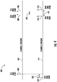
- FIG. 4 depicts an example of a timing diagram 400 for synchronizing multiple control system channels.
- Channel A timeline 402 indicates example timing of the processing system 202A of FIG. 2 relative to channel B timeline 412 of the processing system 202B of FIG. 2 , for instance, as configured in memory system configurations 302A, 302B of FIG. 3 .
- a transmit-A DMA start event 404 indicates a relative point in time where DMA controller 214A begins to transfer the synchronization message A-B 314 from the DMA transmit buffer 308A to the communication interface 222A for transmission to the communication interface 222B of FIG. 2 .
- Transmit-A DMA done event 406 indicates a relative point in time where DMA controller 214A completes transferring the synchronization message A-B 314 from the DMA transmit buffer 308A to the communication interface 222A, resulting in transmitter interrupt 318A of FIG. 3 .
- Transmit-B DMA start event 414 indicates a relative point in time where DMA controller 214B of FIG. 2 begins to transfer the synchronization message B-A 315 of FIG. 3 from the DMA transmit buffer 308B to the communication interface 222B for transmission to the communication interface 222A of FIG. 2 .
- Transmit-B DMA done event 416 indicates a relative point in time where DMA controller 214B completes transferring the synchronization message B-A 315 from the DMA transmit buffer 308B to the communication interface 222B, resulting in transmitter interrupt 318B of FIG. 3 .
- Receive-A DMA done event 408 indicates when the DMA controller 214A completes receiving the synchronization message B-A 315 in DMA receive buffer 310A of FIG.
- receive-B DMA done event 418 indicates when the DMA controller 214B completes receiving the synchronization message A-B 314 in DMA receive buffer 310A of FIG. 3 , resulting in receiver interrupt 320A of FIG. 3 being triggered at the processor core 210A of FIG. 2 .
- a synchronization timing skew 420 represents a time difference between the occurrence of the transmit-A DMA start event 404 and the transmit-B DMA start event 414.
- the value of the synchronization timing skew 420 may be unknown when the transmit-A DMA start event 404 and the transmit-B DMA start event 414 occur.
- the interrupt timer 312A can be used determine how much time elapses between the transmit-A DMA done event 406 and receive-A DMA done event 408 as characterized through detecting the transmitter interrupt 318A and the receiver interrupt 320A, which can occur in any order depending on whether the transmit-A DMA start event 404 leads or lags the transmit-B DMA start event 414.
- the relative order of the transmitter interrupt 318A and the receiver interrupt 320A and time difference 422 can indicate how far out of synchronization the processing system 202A is relative to the processing system 202B.
- time difference 424 between the transmit-B DMA done event 416 and receive-B DMA done event 418 can indicate how far out of synchronization the processing system 202B is relative to the processing system 202A.
- Corrective actions to shorten an execution frame time or extend an execution frame time can be performed by either or both of the processing systems 202A, 202B.
- a control channel serving as a standby control can be adjusted to maintain synchronization with the active control channel.
- the timing adjustment may be split such that each control channel makes a timing adjustment such that the net effect resynchronizes the control channels within a synchronization tolerance.
- FIG. 5 depicts a flow chart of a method 500 in accordance with an embodiment of the disclosure.
- the method 500 can be performed, for example, by the system 200 of FIG. 2 .
- processor core 210A can configure DMA controller 214A to trigger a transmitter interrupt 318A upon transmitting a first synchronization message (e.g., synchronization message A-B 314) from the first processing system 202A to the second processing system 202B.
- a first synchronization message e.g., synchronization message A-B 3114
- the processor core 210A can configure the DMA controller 214A to trigger a receiver interrupt 320A upon receiving a second synchronization message (e.g., synchronization message B-A 315) at the first processing system 202A from the second processing system 202B.
- a second synchronization message e.g., synchronization message B-A 315
- the processor 204A can determine a time difference between triggering of the transmitter interrupt 318A and the receiver interrupt 320A, for instance, using interrupt timer 312A.
- the processor 204A can adjust a synchronization skew of a real-time scheduler 304A based on the time difference to tune real-time synchronization between the first processing system 202A and the second processing system 202B.
- the adjustment can be performed with respect to clock 220A or other parameters of the processing system 202A.
- the method 500 can also be performed by processing system 202B or other processing systems that seek to be dynamically resynchronized.
- the DMA controller 214A can transfer the first synchronization message from a transmit buffer (e.g., DMA transmit buffer 308A) of the memory system 205A to the communication interface 222A absent intervention by the processor core 210A of the first processing system 202A after the processor core 210A configures and enables the DMA controller 214A.
- the processor core 210A can perform one or more other tasks while the DMA controller 214A transfers the first synchronization message from the DMA transmit buffer 308A of the memory system 205A to the communication interface 222A.
- the DMA controller 214A can also be configured to transfer the second synchronization message from the communication interface 222A to a receive buffer (e.g., DMA receive buffer 310A) of the memory system 205A absent intervention by the processor core 210A after the processor core 210A configures and enables the DMA controller 214A.
- the processor core 210A is operable to perform one or more other tasks while the DMA controller 214A transfers the second synchronization message from the communication interface 222A to the receive buffer of the memory system 205A.
- the processor core 210A can be configured to shorten an execution frame time based on determining that the time difference exceeds a synchronization threshold, and the transmitter interrupt 318A occurred after the receiver interrupt 320A. For instance, a next 100 millisecond execution frame could be reduced to 99.99 milliseconds to shorten the execution frame by 10 microseconds.
- the processor core 210A can be configured to extend an execution frame time based on determining the time difference exceeds a synchronization threshold, and the receiver interrupt 320A occurred after the transmitter interrupt 318A. For instance, a next 100 millisecond execution frame could be extended to 100.01 milliseconds to extend the execution frame by 10 microseconds.
- the processor core 210B can be similarly configured with respect to the transmitter interrupt 318B and the receiver interrupt 320B.
- the examples indicating specific time values are provided for purpose of explanation and are not to be construed as limiting to a specific time interval.
- embodiments can be in the form of processor-implemented processes and devices for practicing those processes, such as a processor.
- Embodiments can also be in the form of computer program code containing instructions embodied in tangible media, such as network cloud storage, SD cards, flash drives, floppy diskettes, CD ROMs, hard drives, or any other computer-readable storage medium, wherein, when the computer program code is loaded into and executed by a computer, the computer becomes a device for practicing the embodiments.
- Embodiments can also be in the form of computer program code, for example, whether stored in a storage medium, loaded into and/or executed by a computer, or transmitted over some transmission medium, such as over electrical wiring or cabling, through fiber optics, or via electromagnetic radiation, wherein, when the computer program code is loaded into an executed by a computer, the computer becomes an device for practicing the embodiments.
- the computer program code segments configure the microprocessor to create specific logic circuits.
Landscapes
- Engineering & Computer Science (AREA)
- Theoretical Computer Science (AREA)
- Physics & Mathematics (AREA)
- General Engineering & Computer Science (AREA)
- General Physics & Mathematics (AREA)
- Computer Hardware Design (AREA)
- Software Systems (AREA)
- Mathematical Physics (AREA)
- Automation & Control Theory (AREA)
- Multi Processors (AREA)
Abstract
Description
- Exemplary embodiments pertain to the art of control systems and, more particularly, to real-time processing system synchronization in a control system.
- Control systems can include multiple processing systems that make real-time decisions to control one or more effectors. The processing systems may need to be closely synchronized to make control decisions and provide redundancy in case of a system fault. Synchronization can be implemented through various techniques. A shared real-time clock is one synchronization approach that can provide close synchronization but may require dedicated signal paths and risk a single event upset to multiple systems if the shared real-time clock experiences a fault. Another approach for synchronization is an exchange of handshake and acknowledgement messages between multiple processing systems. This approach can result in busy waiting as processing systems continually poll receiver registers while waiting for a response.
- Disclosed is a system that includes a memory system and a processor of a first processing system including a processor core, a direct memory access controller, and a communication interface. The processor core is configured to execute a plurality of instructions to configure the direct memory access controller to trigger a transmitter interrupt upon transmitting a first synchronization message through the communication interface to a second processing system, configure the direct memory access controller to trigger a receiver interrupt upon receiving a second synchronization message from the second processing system, determine a time difference between triggering of the transmitter interrupt and the receiver interrupt, and adjust a synchronization skew of a real-time scheduler based on the time difference to tune real-time synchronization between the first processing system and the second processing system.
- In addition to one or more of the features described herein, or as an alternative, further embodiments may include where the direct memory access controller is configured to transfer the first synchronization message from a transmit buffer of the memory system to the communication interface absent intervention by the processor core.
- In addition to one or more of the features described herein, or as an alternative, further embodiments may include where the processor core is operable to perform one or more other tasks while the direct memory access controller transfers the first synchronization message from the transmit buffer of the memory system to the communication interface.
- In addition to one or more of the features described herein, or as an alternative, further embodiments may include where the direct memory access controller is configured to transfer the second synchronization message from the communication interface to a receive buffer of the memory system absent intervention by the processor core.
- In addition to one or more of the features described herein, or as an alternative, further embodiments may include where the processor core is operable to perform one or more other tasks while the direct memory access controller transfers the second synchronization message from the communication interface to the receive buffer of the memory system.
- In addition to one or more of the features described herein, or as an alternative, further embodiments may include where the processor core is configured to shorten an execution frame time based on determining that the time difference exceeds a synchronization threshold, and the transmitter interrupt occurred after the receiver interrupt.
- In addition to one or more of the features described herein, or as an alternative, further embodiments may include where the processor core is configured to extend an execution frame time based on determining the time difference exceeds a synchronization threshold, and the receiver interrupt occurred after the transmitter interrupt.
- In addition to one or more of the features described herein, or as an alternative, further embodiments may include where the communication interface includes a Universal Asynchronous Receiver/Transmitter.
- In addition to one or more of the features described herein, or as an alternative, further embodiments may include where the first processing system and/or the second processing system are part of a real-time controller of a control system.
- In addition to one or more of the features described herein, or as an alternative, further embodiments may include where the control system is a controller of an elevator system.
- Also disclosed is a method that includes configuring a direct memory access controller to trigger a transmitter interrupt upon transmitting a first synchronization message from a first processing system through a communication interface to a second processing system. The direct memory access controller is configured to trigger a receiver interrupt upon receiving a second synchronization message at the first processing system from the second processing system. A time difference between triggering of the transmitter interrupt and the receiver interrupt is determined. A synchronization skew of a real-time scheduler is adjusted based on the time difference to tune real-time synchronization between the first processing system and the second processing system.
- In addition to one or more of the features described herein, or as an alternative, further embodiments may include transferring, by the direct memory access controller, the first synchronization message from a transmit buffer of the memory system to the communication interface absent intervention by a processor core of the first processing system.
- In addition to one or more of the features described herein, or as an alternative, further embodiments may include performing one or more other tasks, by the processor core, while the direct memory access controller transfers the first synchronization message from the transmit buffer of the memory system to the communication interface.
- In addition to one or more of the features described herein, or as an alternative, further embodiments may include transferring, by the direct memory access controller, the second synchronization message from the communication interface to a receive buffer of the memory system absent intervention by the processor core.
- In addition to one or more of the features described herein, or as an alternative, further embodiments may include performing one or more other tasks, by the processor core, while the direct memory access controller transfers the second synchronization message from the communication interface to the receive buffer of the memory system.
- In addition to one or more of the features described herein, or as an alternative, further embodiments may include shortening an execution frame time based on determining that the time difference exceeds a synchronization threshold, and the transmitter interrupt occurred after the receiver interrupt.
- In addition to one or more of the features described herein, or as an alternative, further embodiments may include extending an execution frame time based on determining that the time difference exceeds a synchronization threshold, and the receiver interrupt occurred after the transmitter interrupt.
- The following descriptions should not be considered limiting in any way. With reference to the accompanying drawings, like elements are numbered alike:
-
FIG. 1 is a schematic illustration of an elevator system according to an embodiment of the present disclosure; -
FIG. 2 depicts a system with multiple synchronized processing systems, according to an embodiment of the present disclosure; -
FIG. 3 depicts memory system configurations for synchronizing multiple processing systems, according to an embodiment of the present disclosure; -
FIG. 4 depicts a timing diagram for synchronizing multiple control system channels, according to an embodiment of the present disclosure; and -
FIG. 5 is a flow diagram illustrating a process, according to an embodiment of the present disclosure. - A detailed description of one or more embodiments of the disclosed apparatus and method are presented herein by way of exemplification and not limitation with reference to the Figures.
-
FIG. 1 is a perspective view of anelevator system 101 including anelevator car 103, acounterweight 105, atension member 107, aguide rail 109, amachine 111, aposition reference system 113, and acontroller 115. Theelevator car 103 andcounterweight 105 are connected to each other by thetension member 107. Thetension member 107 may include or be configured as, for example, ropes, steel cables, and/or coated-steel belts. Thecounterweight 105 is configured to balance a load of theelevator car 103 and is configured to facilitate movement of theelevator car 103 concurrently and in an opposite direction with respect to thecounterweight 105 within anelevator hoistway 117 and along theguide rail 109. - The
tension member 107 engages themachine 111, which is part of an overhead structure of theelevator system 101. Themachine 111 is configured to control movement between theelevator car 103 and thecounterweight 105. Theposition reference system 113 may be mounted on a fixed part at the top of theelevator hoistway 117, such as on a support or guide rail, and may be configured to provide position signals related to a position of theelevator car 103 within theelevator hoistway 117. In other embodiments, theposition reference system 113 may be directly mounted to a moving component of themachine 111, or may be located in other positions and/or configurations as known in the art. Theposition reference system 113 can be any device or mechanism for monitoring a position of an elevator car and/or counterweight, as known in the art. For example, without limitation, theposition reference system 113 can be an encoder, sensor, or other system and can include velocity sensing, absolute position sensing, etc., as will be appreciated by those of skill in the art. - The
controller 115 is located, as shown, in acontroller room 121 of theelevator hoistway 117 and is configured to control the operation of theelevator system 101, and particularly theelevator car 103. For example, thecontroller 115 may provide drive signals to themachine 111 to control the acceleration, deceleration, leveling, stopping, etc. of theelevator car 103. Thecontroller 115 may also be configured to receive position signals from theposition reference system 113 or any other desired position reference device. When moving up or down within theelevator hoistway 117 alongguide rail 109, theelevator car 103 may stop at one ormore landings 125 as controlled by thecontroller 115. Although shown in acontroller room 121, those of skill in the art will appreciate that thecontroller 115 can be located and/or configured in other locations or positions within theelevator system 101. In one embodiment, the controller may be located remotely or in the cloud. - The
machine 111 may include a motor or similar driving mechanism. In accordance with embodiments of the disclosure, themachine 111 is configured to include an electrically driven motor. The power supply for the motor may be any power source, including a power grid, which, in combination with other components, is supplied to the motor. Themachine 111 may include a traction sheave that imparts force totension member 107 to move theelevator car 103 withinelevator hoistway 117. - Although shown and described with a roping system including
tension member 107, elevator systems that employ other methods and mechanisms of moving an elevator car within an elevator hoistway may employ embodiments of the present disclosure. For example, embodiments may be employed in ropeless elevator systems using a linear motor to impart motion to an elevator car. Embodiments may also be employed in ropeless elevator systems using a hydraulic lift to impart motion to an elevator car. Embodiments may also be employed in ropeless elevator systems using self-propelled elevator cars (e.g., elevator cars equipped with friction wheels or traction wheels). Other embodiments can include escalators, moving walkways, or other transportation systems. Further embodiments can include any multiprocessing system configured for real-time synchronous operation.FIG. 1 is merely a nonlimiting example presented for illustrative and explanatory purposes. - Turning now to
FIG. 2 , anexemplary system 200 for synchronized real-time control in accordance with one or more embodiments is shown. Thesystem 200 may include at least twoprocessing systems processing systems controller 115 ofFIG. 1 . For example,processing systems controller 115 to enhance reliability of thecontroller 115 such that one of theprocessing systems elevator system 101 ofFIG. 1 in the event of a fault in the other. Although described with respect to thecontroller 115 ofFIG. 1 , it will be understood that thesystem 200 can be implemented in any type of real-time synchronized multi-channel system. As used herein, the term "channel" refers to a separate instance of theprocessing system - The
processing systems processors memory systems external memory memory buses processors processor cores memory controllers controllers controllers internal memory clocks communication interface transmitters receivers memory systems memory controllers internal memory - The communication interfaces 222A, 222B can each include a Universal Asynchronous Receiver/Transmitter (UART) to manage incremental (e.g., bitwise) transmission of status and data between the
processing systems transmitter 224A ofcommunication interface 222A is configured to communicate with thereceiver 226B of thecommunication interface 222B through afirst communication link 228. Thetransmitter 224B ofcommunication interface 222B is configured to communicate with thereceiver 226A of thecommunication interface 222A through asecond communication link 230. The communication links 228, 230 can be unidirectional or bidirectional communication paths that support cross-channel communication between theprocessing systems processors machine 111 ofFIG. 1 , through I/O links 234A, 234B. Although themachine 111 ofFIG. 1 is one example, the I/O links 234A, 234B can interface with various types of I/O devices, such as sensors and effectors of real-time control systems. - The
processor cores external memory internal memory external memory internal memory memory controllers DMA controllers communication interfaces memory systems processor cores communication interfaces processor cores DMA controllers communication interfaces communication interfaces DMA controllers memory systems processor cores - The interrupt
controllers processor cores processor core 210A can configure the interruptcontroller 216A to trigger a DMA transmit interrupt when theDMA controller 214A completes sending a message having a predetermined size to thecommunication interface 222A for transmission toprocessing system 202B. Theprocessor core 210A can also provide theDMA controller 214A with a transmit buffer location in theexternal memory 206A or theinternal memory 218A to be read for transfer to thecommunication interface 222A. After the contents of the message is loaded into the transmit buffer, theDMA controller 214A can be configured to transfer the contents to thecommunication interface 222A, with the interruptcontroller 216A triggering an interrupt to theprocessor core 210A upon completing the transfer. Depending on the message size, throughput of thecommunication link 228 and other factors, transmission of a message can take a variable amount of time. Theprocessor core 210A is free to perform one or more other tasks while the message is transmitted. For example, application tasks, diagnostic tasks, or other such tasks can be performed that do not directly involve thecommunication interface 222A while theDMA controller 214A actively transfers data to and from thecommunication interface 222A. A similar approach can be taken for receiving messages oncommunication link 230, routing the message to a receive buffer of theprocessing system 202A, and triggering an interrupt to theprocessor core 210A upon receiving and transferring a predetermined amount of message data by theDMA controller 214A. Further, a similar process can be followed by theprocessing system 202B. Although depicted separately, theDMA controller 214A and interruptcontroller 216A can be combined. Similarly, theDMA controller 214B and interruptcontroller 216B can be combined. - In embodiments, the
clocks processing systems processing systems clocks -
FIG. 3 depicts an example of asynchronization system 300 according to an embodiment. Thesynchronization system 300 includes amemory system configuration 302A ofprocessing system 202A ofFIG. 2 and amemory system configuration 302B ofprocessing system 202B ofFIG. 2 . Thememory system configurations memory systems FIG. 2 to support real-time synchronization, for instance, using any combination of theexternal memory internal memory FIG. 2 . Thememory system configurations time schedulers applications buffers buffers timers 312A, 312B. The real-time schedulers applications time schedulers processing systems FIG. 2 to periodically adjust a synchronization skew such that synchronization is maintained over longer-term operation. Theapplications FIG. 2 and determining one or more commands to control effectors through the I/O interfaces 232A, 232B ofFIG. 2 , such as controlling themachine 111 ofFIG. 1 . - As one example, the real-
time scheduler 304A can include instructions executable by theprocessor core 210A ofFIG. 2 to load the DMA transmitbuffer 308A with asynchronization message A-B 314. Theapplication 306A may load the DMA transmitbuffer 308A with anapplication message 316 for theprocessing system 202B ofFIG. 2 . TheDMA controller 214A ofFIG. 2 can be configured to transfer the synchronization message A-B 314 from the DMA transmitbuffer 308A through thecommunication interface 222A ofFIG. 2 to the DMA receivebuffer 310B. Upon completing the transfer ofsynchronization message A-B 314, a transmitter interrupt 318A can be triggered to theprocessor core 210A ofFIG. 2 . Upon theDMA controller 214B completing transferring the synchronization message A-B 314 from thecommunication interface 222B ofFIG. 2 into the DMA receivebuffer 310B, a receiver interrupt 320B can be triggered to theprocessor core 210B ofFIG. 2 .DMA controller 214A can continue with transferring theapplication message 316 to thecommunication interface 222A ofFIG. 2 after synchronization message A-B 314 is transferred. - The
DMA controller 214B can transfer a synchronization message B-A 315 from DMA transmitbuffer 308B through thecommunication interface 222B ofFIG. 2 to the DMA receivebuffer 310A. Upon completing the transfer ofsynchronization message B-A 315, a transmitter interrupt 318B can be triggered to theprocessor core 210B ofFIG. 2 . Upon theDMA controller 214A completing transferring the synchronization message B-A 315 from thecommunication interface 222A ofFIG. 2 into the DMA receivebuffer 310A, a receiver interrupt 320A can be triggered to theprocessor core 210A ofFIG. 2 . Interrupt timer 312A can be used to track a time difference between transmitter interrupt 318A and receiver interrupt 320A. Similarly, interrupttimer 312B can be used to track a time difference between transmitter interrupt 318B and receiver interrupt 320B. -
FIG. 4 depicts an example of a timing diagram 400 for synchronizing multiple control system channels.Channel A timeline 402 indicates example timing of theprocessing system 202A ofFIG. 2 relative to channelB timeline 412 of theprocessing system 202B ofFIG. 2 , for instance, as configured inmemory system configurations FIG. 3 . In the example ofFIG. 4 , a transmit-ADMA start event 404 indicates a relative point in time whereDMA controller 214A begins to transfer the synchronization message A-B 314 from the DMA transmitbuffer 308A to thecommunication interface 222A for transmission to thecommunication interface 222B ofFIG. 2 . Transmit-A DMA doneevent 406 indicates a relative point in time whereDMA controller 214A completes transferring the synchronization message A-B 314 from the DMA transmitbuffer 308A to thecommunication interface 222A, resulting in transmitter interrupt 318A ofFIG. 3 . - Transmit-B
DMA start event 414 indicates a relative point in time whereDMA controller 214B ofFIG. 2 begins to transfer the synchronization message B-A 315 ofFIG. 3 from the DMA transmitbuffer 308B to thecommunication interface 222B for transmission to thecommunication interface 222A ofFIG. 2 . Transmit-B DMA doneevent 416 indicates a relative point in time whereDMA controller 214B completes transferring the synchronization message B-A 315 from the DMA transmitbuffer 308B to thecommunication interface 222B, resulting in transmitter interrupt 318B ofFIG. 3 . Receive-A DMA doneevent 408 indicates when theDMA controller 214A completes receiving the synchronization message B-A 315 in DMA receivebuffer 310A ofFIG. 3 , resulting in receiver interrupt 320A ofFIG. 3 being triggered at theprocessor core 210A ofFIG. 2 . Similarly, receive-B DMA doneevent 418 indicates when theDMA controller 214B completes receiving the synchronization message A-B 314 in DMA receivebuffer 310A ofFIG. 3 , resulting in receiver interrupt 320A ofFIG. 3 being triggered at theprocessor core 210A ofFIG. 2 . - A
synchronization timing skew 420 represents a time difference between the occurrence of the transmit-ADMA start event 404 and the transmit-BDMA start event 414. The value of thesynchronization timing skew 420 may be unknown when the transmit-ADMA start event 404 and the transmit-BDMA start event 414 occur. The interrupt timer 312A can be used determine how much time elapses between the transmit-A DMA doneevent 406 and receive-A DMA doneevent 408 as characterized through detecting the transmitter interrupt 318A and the receiver interrupt 320A, which can occur in any order depending on whether the transmit-ADMA start event 404 leads or lags the transmit-BDMA start event 414. The relative order of the transmitter interrupt 318A and the receiver interrupt 320A andtime difference 422 can indicate how far out of synchronization theprocessing system 202A is relative to theprocessing system 202B. Similarly,time difference 424 between the transmit-B DMA doneevent 416 and receive-B DMA doneevent 418 can indicate how far out of synchronization theprocessing system 202B is relative to theprocessing system 202A. - Corrective actions to shorten an execution frame time or extend an execution frame time can be performed by either or both of the
processing systems processing systems - Referring now to
FIG. 5 with continued reference toFIGS. 1-5 ,FIG. 5 depicts a flow chart of amethod 500 in accordance with an embodiment of the disclosure. Themethod 500 can be performed, for example, by thesystem 200 ofFIG. 2 . - At
block 502,processor core 210A can configureDMA controller 214A to trigger a transmitter interrupt 318A upon transmitting a first synchronization message (e.g., synchronization message A-B 314) from thefirst processing system 202A to thesecond processing system 202B. - At
block 504, theprocessor core 210A can configure theDMA controller 214A to trigger a receiver interrupt 320A upon receiving a second synchronization message (e.g., synchronization message B-A 315) at thefirst processing system 202A from thesecond processing system 202B. - At block 506, the
processor 204A can determine a time difference between triggering of the transmitter interrupt 318A and the receiver interrupt 320A, for instance, using interrupt timer 312A. - At
block 508, theprocessor 204A can adjust a synchronization skew of a real-time scheduler 304A based on the time difference to tune real-time synchronization between thefirst processing system 202A and thesecond processing system 202B. The adjustment can be performed with respect toclock 220A or other parameters of theprocessing system 202A. Themethod 500 can also be performed byprocessing system 202B or other processing systems that seek to be dynamically resynchronized. - In some embodiments, the
DMA controller 214A can transfer the first synchronization message from a transmit buffer (e.g., DMA transmitbuffer 308A) of thememory system 205A to thecommunication interface 222A absent intervention by theprocessor core 210A of thefirst processing system 202A after theprocessor core 210A configures and enables theDMA controller 214A. Theprocessor core 210A can perform one or more other tasks while theDMA controller 214A transfers the first synchronization message from the DMA transmitbuffer 308A of thememory system 205A to thecommunication interface 222A. TheDMA controller 214A can also be configured to transfer the second synchronization message from thecommunication interface 222A to a receive buffer (e.g., DMA receivebuffer 310A) of thememory system 205A absent intervention by theprocessor core 210A after theprocessor core 210A configures and enables theDMA controller 214A. Theprocessor core 210A is operable to perform one or more other tasks while theDMA controller 214A transfers the second synchronization message from thecommunication interface 222A to the receive buffer of thememory system 205A. - In some embodiments, the
processor core 210A can be configured to shorten an execution frame time based on determining that the time difference exceeds a synchronization threshold, and the transmitter interrupt 318A occurred after the receiver interrupt 320A. For instance, a next 100 millisecond execution frame could be reduced to 99.99 milliseconds to shorten the execution frame by 10 microseconds. Theprocessor core 210A can be configured to extend an execution frame time based on determining the time difference exceeds a synchronization threshold, and the receiver interrupt 320A occurred after the transmitter interrupt 318A. For instance, a next 100 millisecond execution frame could be extended to 100.01 milliseconds to extend the execution frame by 10 microseconds. Theprocessor core 210B can be similarly configured with respect to the transmitter interrupt 318B and the receiver interrupt 320B. The examples indicating specific time values are provided for purpose of explanation and are not to be construed as limiting to a specific time interval. - While the above description has described the flow process of
FIG. 5 in a particular order, it should be appreciated that unless otherwise specifically required in the attached claims that the ordering of the steps may be varied. - As described above, embodiments can be in the form of processor-implemented processes and devices for practicing those processes, such as a processor. Embodiments can also be in the form of computer program code containing instructions embodied in tangible media, such as network cloud storage, SD cards, flash drives, floppy diskettes, CD ROMs, hard drives, or any other computer-readable storage medium, wherein, when the computer program code is loaded into and executed by a computer, the computer becomes a device for practicing the embodiments. Embodiments can also be in the form of computer program code, for example, whether stored in a storage medium, loaded into and/or executed by a computer, or transmitted over some transmission medium, such as over electrical wiring or cabling, through fiber optics, or via electromagnetic radiation, wherein, when the computer program code is loaded into an executed by a computer, the computer becomes an device for practicing the embodiments. When implemented on a general-purpose microprocessor, the computer program code segments configure the microprocessor to create specific logic circuits.
- The term "about" is intended to include the degree of error associated with measurement of the particular quantity based upon the equipment available at the time of filing the application.
- The terminology used herein is for the purpose of describing particular embodiments only and is not intended to be limiting of the present disclosure. As used herein, the singular forms "a", "an" and "the" are intended to include the plural forms as well, unless the context clearly indicates otherwise. It will be further understood that the terms "comprises" and/or "comprising," when used in this specification, specify the presence of stated features, integers, steps, operations, elements, and/or components, but do not preclude the presence or addition of one or more other features, integers, steps, operations, element components, and/or groups thereof.
- While the present disclosure has been described with reference to an exemplary embodiment or embodiments, it will be understood by those skilled in the art that various changes may be made and equivalents may be substituted for elements thereof without departing from the scope of the present disclosure. In addition, many modifications may be made to adapt a particular situation or material to the teachings of the present disclosure without departing from the essential scope thereof. Therefore, it is intended that the present disclosure not be limited to the particular embodiment disclosed as the best mode contemplated for carrying out this present disclosure, but that the present disclosure will include all embodiments falling within the scope of the claims.
Claims (15)
- A system comprising:a memory system; anda processor of a first processing system comprising a processor core, a direct memory access controller, and a communication interface, the processor core configured to execute a plurality of instructions to:configure the direct memory access controller to trigger a transmitter interrupt upon transmitting a first synchronization message through the communication interface to a second processing system;configure the direct memory access controller to trigger a receiver interrupt upon receiving a second synchronization message from the second processing system;determine a time difference between triggering of the transmitter interrupt and the receiver interrupt; andadjust a synchronization skew of a real-time scheduler based on the time difference to tune real-time synchronization between the first processing system and the second processing system.
- The system of claim 1, wherein the direct memory access controller is configured to transfer the first synchronization message from a transmit buffer of the memory system to the communication interface absent intervention by the processor core.
- The system of claim 2, wherein the processor core is operable to perform one or more other tasks while the direct memory access controller transfers the first synchronization message from the transmit buffer of the memory system to the communication interface.
- The system of any preceding claim, wherein the direct memory access controller is configured to transfer the second synchronization message from the communication interface to a receive buffer of the memory system absent intervention by the processor core.
- The system of claim 4, wherein the processor core is operable to perform one or more other tasks while the direct memory access controller transfers the second synchronization message from the communication interface to the receive buffer of the memory system.
- The system of any preceding claim, wherein the processor core is configured to shorten an execution frame time based on determining that the time difference exceeds a synchronization threshold, and the transmitter interrupt occurred after the receiver interrupt.
- The system of any preceding claim, wherein the processor core is configured to extend an execution frame time based on determining the time difference exceeds a synchronization threshold, and the receiver interrupt occurred after the transmitter interrupt.
- The system of any preceding claim, wherein the communication interface comprises a Universal Asynchronous Receiver/Transmitter.
- The system of any preceding claim, wherein the first processing system and the second processing system comprise a real-time controller of a control system; and optionally wherein the control system is a controller of an elevator system.
- A method comprising:configuring a direct memory access controller to trigger a transmitter interrupt upon transmitting a first synchronization message from a first processing system through a communication interface to a second processing system;configuring the direct memory access controller to trigger a receiver interrupt upon receiving a second synchronization message at the first processing system from the second processing system;determining a time difference between triggering of the transmitter interrupt and the receiver interrupt; andadjusting a synchronization skew of a real-time scheduler based on the time difference to tune real-time synchronization between the first processing system and the second processing system.
- The method of claim 10, further comprising:
transferring, by the direct memory access controller, the first synchronization message from a transmit buffer of the memory system to the communication interface absent intervention by a processor core of the first processing system; and optionally further comprising:
performing one or more other tasks, by the processor core, while the direct memory access controller transfers the first synchronization message from the transmit buffer of the memory system to the communication interface. - The method of claim 10 or 11, further comprising:
transferring, by the direct memory access controller, the second synchronization message from the communication interface to a receive buffer of the memory system absent intervention by the processor core; and optionally further comprising:
performing one or more other tasks, by the processor core, while the direct memory access controller transfers the second synchronization message from the communication interface to the receive buffer of the memory system. - The method of any of claims 10 to 12, further comprising:
shortening an execution frame time based on determining that the time difference exceeds a synchronization threshold, and the transmitter interrupt occurred after the receiver interrupt; and/or further comprising:
extending an execution frame time based on determining that the time difference exceeds a synchronization threshold, and the receiver interrupt occurred after the transmitter interrupt. - The method of any of claims 10 to 13, wherein the communication interface comprises a Universal Asynchronous Receiver/Transmitter.
- The method of any of claims 10 to 14, wherein the first processing system and the second processing system comprise a real-time controller of a control system; and optionally wherein the control system is a controller of an elevator system.
Applications Claiming Priority (1)
| Application Number | Priority Date | Filing Date | Title |
|---|---|---|---|
| US17/128,725 US11360918B1 (en) | 2020-12-21 | 2020-12-21 | Real-time processing system synchronization in a control system |
Publications (1)
| Publication Number | Publication Date |
|---|---|
| EP4016302A1 true EP4016302A1 (en) | 2022-06-22 |
Family
ID=78676314
Family Applications (1)
| Application Number | Title | Priority Date | Filing Date |
|---|---|---|---|
| EP21208447.9A Pending EP4016302A1 (en) | 2020-12-21 | 2021-11-16 | Real-time processing system synchronization in a control system |
Country Status (3)
| Country | Link |
|---|---|
| US (1) | US11360918B1 (en) |
| EP (1) | EP4016302A1 (en) |
| CN (1) | CN114647601B (en) |
Families Citing this family (4)
| Publication number | Priority date | Publication date | Assignee | Title |
|---|---|---|---|---|
| US12238663B2 (en) * | 2022-07-21 | 2025-02-25 | Tokyo Electron Limited | Wireless communication system, wireless communication method, control device, and control method |
| CN116722962B (en) * | 2022-09-05 | 2024-07-12 | 荣耀终端有限公司 | Interrupt processing method, communication device, communication equipment and chip system |
| US12182043B2 (en) * | 2022-09-27 | 2024-12-31 | Htc Corporation | Signal transceiving device and signal transceiving method thereof |
| US20240289349A1 (en) * | 2023-02-23 | 2024-08-29 | Hewlett Packard Enterprise Development Lp | Database synchronization based on memory transfer |
Citations (3)
| Publication number | Priority date | Publication date | Assignee | Title |
|---|---|---|---|---|
| US5790776A (en) * | 1992-12-17 | 1998-08-04 | Tandem Computers Incorporated | Apparatus for detecting divergence between a pair of duplexed, synchronized processor elements |
| US20170041897A1 (en) * | 2013-11-12 | 2017-02-09 | Qualcomm Incorporated | Apparatus and methods for synchronizing a controller and sensors |
| US20170300447A1 (en) * | 2014-10-07 | 2017-10-19 | Safran Electronics & Defense | System on a chip having high operating certainty |
Family Cites Families (21)
| Publication number | Priority date | Publication date | Assignee | Title |
|---|---|---|---|---|
| KR20000013078A (en) * | 1998-08-04 | 2000-03-06 | 윤종용 | Communication device between processors of multiple processor system and communication method |
| US8327448B2 (en) * | 2005-06-22 | 2012-12-04 | Intel Corporation | Protected clock management based upon a non-trusted persistent time source |
| GB2443277B (en) * | 2006-10-24 | 2011-05-18 | Advanced Risc Mach Ltd | Performing diagnostics operations upon an asymmetric multiprocessor apparatus |
| US8194146B2 (en) * | 2008-01-11 | 2012-06-05 | Mediatek Inc. | Apparatuses for capturing and storing real-time images |
| WO2010080173A1 (en) * | 2009-01-12 | 2010-07-15 | Rambus Inc. | Mesochronous signaling system with clock-stopped low power mode |
| US8321614B2 (en) * | 2009-04-24 | 2012-11-27 | Empire Technology Development Llc | Dynamic scheduling interrupt controller for multiprocessors |
| JP2011186591A (en) * | 2010-03-05 | 2011-09-22 | Renesas Electronics Corp | Processor and control method therefor |
| WO2012033769A1 (en) * | 2010-09-06 | 2012-03-15 | Psiber Data Pte. Ltd. | System and apparatus for testing cable |
| US8516355B2 (en) * | 2011-02-16 | 2013-08-20 | Invensys Systems, Inc. | System and method for fault tolerant computing using generic hardware |
| CN102571317B (en) * | 2012-01-06 | 2016-04-27 | 因诺微科技(天津)有限公司 | Based on the method for data synchronization of pci bus and system in software radio system |
| CN102866971B (en) * | 2012-08-28 | 2015-11-25 | 华为技术有限公司 | Device, the system and method for transmission data |
| KR101468677B1 (en) * | 2013-12-27 | 2014-12-05 | (주)실리콘화일 | Memory access contol circuit using arbiter |
| EP3054384B1 (en) * | 2015-02-04 | 2018-06-27 | Huawei Technologies Co., Ltd. | System and method for memory synchronization of a multi-core system |
| CN107402534B (en) * | 2017-07-21 | 2021-02-19 | 上海新时达机器人有限公司 | Adjusting method, EtherCAT main station and computer readable storage medium |
| US10969821B2 (en) * | 2018-05-29 | 2021-04-06 | Xilinx, Inc. | Latency synchronization across clock domains |
| CN109189717B (en) * | 2018-09-07 | 2021-12-03 | 郑州信大先进技术研究院 | Multisource data synchronous acquisition system |
| US10991194B2 (en) * | 2018-10-05 | 2021-04-27 | Aristocrat Technologies Australia Pty Limited | Systems and methods for synchronously illuminating lighting components of an electronic gaming machine |
| CN109633318B (en) * | 2018-12-21 | 2021-05-07 | 国网北京市电力公司 | Method and device for synchronizing electric signal and communication signal, storage medium and processor |
| CN109819512B (en) * | 2019-03-18 | 2020-12-08 | 云南航天工程物探检测股份有限公司 | Engineering CT wireless distributed multi-channel ADC high-precision synchronization system and method |
| CN110597744B (en) * | 2019-08-30 | 2023-05-30 | 深圳震有科技股份有限公司 | Data synchronous transmission method, system and computer equipment |
| CN110636603A (en) * | 2019-10-22 | 2019-12-31 | 深圳市道通智能航空技术有限公司 | Aircraft time synchronization system and method |
-
2020
- 2020-12-21 US US17/128,725 patent/US11360918B1/en active Active
-
2021
- 2021-08-19 CN CN202110957633.1A patent/CN114647601B/en active Active
- 2021-11-16 EP EP21208447.9A patent/EP4016302A1/en active Pending
Patent Citations (3)
| Publication number | Priority date | Publication date | Assignee | Title |
|---|---|---|---|---|
| US5790776A (en) * | 1992-12-17 | 1998-08-04 | Tandem Computers Incorporated | Apparatus for detecting divergence between a pair of duplexed, synchronized processor elements |
| US20170041897A1 (en) * | 2013-11-12 | 2017-02-09 | Qualcomm Incorporated | Apparatus and methods for synchronizing a controller and sensors |
| US20170300447A1 (en) * | 2014-10-07 | 2017-10-19 | Safran Electronics & Defense | System on a chip having high operating certainty |
Also Published As
| Publication number | Publication date |
|---|---|
| CN114647601A (en) | 2022-06-21 |
| US11360918B1 (en) | 2022-06-14 |
| CN114647601B (en) | 2024-12-03 |
Similar Documents
| Publication | Publication Date | Title |
|---|---|---|
| CN114647601B (en) | Real-time processing system synchronization in control systems | |
| US9505560B2 (en) | System and method for controlling a moving element in a linear motor conveyor | |
| JP4468224B2 (en) | Elevator position detection system and method | |
| US7996104B2 (en) | Driver board control system for modular conveyor with address-based network for inter-conveyer communication | |
| CN101261510B (en) | Numerical controller with abnormal motor deceleration stop control means | |
| JP6013622B2 (en) | Control system for vehicles in a guideway network | |
| EP2687471B1 (en) | Elevator control device | |
| EP3543919A1 (en) | Service tool with capture and replay | |
| JP2003095555A (en) | Control device of elevator | |
| US12427667B2 (en) | Robot system, method for controlling robot system, method for manufacturing article using robot system, system, method for controlling system, and recording medium | |
| CN112678468B (en) | Rolling machine and positioning method thereof | |
| US9694986B2 (en) | Transport device and transport method for transporting a fragile object | |
| TW202347952A (en) | Drive device, drive method, and drive program | |
| CN114074881B (en) | Elevator car mover that provides intelligent control based on battery state of charge | |
| US12547180B2 (en) | Controller, automated guided vehicles and method of guiding a platoon of automated guided vehicles | |
| CN113716438B (en) | Escalator with distributed state sensors | |
| EP4382468B1 (en) | Elevator system configured to perform a self diagnosis and method of operating the elevator system | |
| EP3915927B1 (en) | Escalator steps with strain sensors | |
| JP2019001615A (en) | Elevator control device and elevator control method | |
| JP4385404B2 (en) | Motor drive device and method for emergency stop of motor drive device | |
| EP1837727B1 (en) | Self-synchronous AC servo system for high-speed serial communication | |
| CN111958583A (en) | Robot control device, robot system, and robot control method | |
| CN116588636B (en) | Single track multi-section type transmission control method and system and storage medium | |
| JPH10254545A (en) | Control method and simulation method | |
| US20260015206A1 (en) | Method and apparatus for detecting the state of a plurality of layer door switches |
Legal Events
| Date | Code | Title | Description |
|---|---|---|---|
| PUAI | Public reference made under article 153(3) epc to a published international application that has entered the european phase |
Free format text: ORIGINAL CODE: 0009012 |
|
| STAA | Information on the status of an ep patent application or granted ep patent |
Free format text: STATUS: THE APPLICATION HAS BEEN PUBLISHED |
|
| AK | Designated contracting states |
Kind code of ref document: A1 Designated state(s): AL AT BE BG CH CY CZ DE DK EE ES FI FR GB GR HR HU IE IS IT LI LT LU LV MC MK MT NL NO PL PT RO RS SE SI SK SM TR |
|
| STAA | Information on the status of an ep patent application or granted ep patent |
Free format text: STATUS: REQUEST FOR EXAMINATION WAS MADE |
|
| 17P | Request for examination filed |
Effective date: 20221216 |
|
| RBV | Designated contracting states (corrected) |
Designated state(s): AL AT BE BG CH CY CZ DE DK EE ES FI FR GB GR HR HU IE IS IT LI LT LU LV MC MK MT NL NO PL PT RO RS SE SI SK SM TR |
|
| GRAP | Despatch of communication of intention to grant a patent |
Free format text: ORIGINAL CODE: EPIDOSNIGR1 |
|
| STAA | Information on the status of an ep patent application or granted ep patent |
Free format text: STATUS: GRANT OF PATENT IS INTENDED |
|
| INTG | Intention to grant announced |
Effective date: 20260218 |