EP4016026B1 - Kraftaufnehmer - Google Patents
Kraftaufnehmer Download PDFInfo
- Publication number
- EP4016026B1 EP4016026B1 EP21214849.8A EP21214849A EP4016026B1 EP 4016026 B1 EP4016026 B1 EP 4016026B1 EP 21214849 A EP21214849 A EP 21214849A EP 4016026 B1 EP4016026 B1 EP 4016026B1
- Authority
- EP
- European Patent Office
- Prior art keywords
- sensing
- electrodes
- cavity
- force
- sensor
- Prior art date
- Legal status (The legal status is an assumption and is not a legal conclusion. Google has not performed a legal analysis and makes no representation as to the accuracy of the status listed.)
- Active
Links
Images






Classifications
-
- G—PHYSICS
- G01—MEASURING; TESTING
- G01L—MEASURING FORCE, STRESS, TORQUE, WORK, MECHANICAL POWER, MECHANICAL EFFICIENCY, OR FLUID PRESSURE
- G01L5/00—Apparatus for, or methods of, measuring force, work, mechanical power, or torque, specially adapted for specific purposes
- G01L5/16—Apparatus for, or methods of, measuring force, work, mechanical power, or torque, specially adapted for specific purposes for measuring several components of force
- G01L5/161—Apparatus for, or methods of, measuring force, work, mechanical power, or torque, specially adapted for specific purposes for measuring several components of force using variations in ohmic resistance
- G01L5/162—Apparatus for, or methods of, measuring force, work, mechanical power, or torque, specially adapted for specific purposes for measuring several components of force using variations in ohmic resistance of piezoresistors
-
- G—PHYSICS
- G06—COMPUTING OR CALCULATING; COUNTING
- G06F—ELECTRIC DIGITAL DATA PROCESSING
- G06F3/00—Input arrangements for transferring data to be processed into a form capable of being handled by the computer; Output arrangements for transferring data from processing unit to output unit, e.g. interface arrangements
- G06F3/01—Input arrangements or combined input and output arrangements for interaction between user and computer
- G06F3/03—Arrangements for converting the position or the displacement of a member into a coded form
- G06F3/041—Digitisers, e.g. for touch screens or touch pads, characterised by the transducing means
- G06F3/0414—Digitisers, e.g. for touch screens or touch pads, characterised by the transducing means using force sensing means to determine a position
- G06F3/04144—Digitisers, e.g. for touch screens or touch pads, characterised by the transducing means using force sensing means to determine a position using an array of force sensing means
-
- G—PHYSICS
- G01—MEASURING; TESTING
- G01L—MEASURING FORCE, STRESS, TORQUE, WORK, MECHANICAL POWER, MECHANICAL EFFICIENCY, OR FLUID PRESSURE
- G01L1/00—Measuring force or stress, in general
- G01L1/14—Measuring force or stress, in general by measuring variations in capacitance or inductance of electrical elements, e.g. by measuring variations of frequency of electrical oscillators
- G01L1/142—Measuring force or stress, in general by measuring variations in capacitance or inductance of electrical elements, e.g. by measuring variations of frequency of electrical oscillators using capacitors
- G01L1/146—Measuring force or stress, in general by measuring variations in capacitance or inductance of electrical elements, e.g. by measuring variations of frequency of electrical oscillators using capacitors for measuring force distributions, e.g. using force arrays
-
- G—PHYSICS
- G01—MEASURING; TESTING
- G01L—MEASURING FORCE, STRESS, TORQUE, WORK, MECHANICAL POWER, MECHANICAL EFFICIENCY, OR FLUID PRESSURE
- G01L1/00—Measuring force or stress, in general
- G01L1/20—Measuring force or stress, in general by measuring variations in ohmic resistance of solid materials or of electrically-conductive fluids; by making use of electrokinetic cells, i.e. liquid-containing cells wherein an electrical potential is produced or varied upon the application of stress
- G01L1/205—Measuring force or stress, in general by measuring variations in ohmic resistance of solid materials or of electrically-conductive fluids; by making use of electrokinetic cells, i.e. liquid-containing cells wherein an electrical potential is produced or varied upon the application of stress using distributed sensing elements
-
- G—PHYSICS
- G01—MEASURING; TESTING
- G01L—MEASURING FORCE, STRESS, TORQUE, WORK, MECHANICAL POWER, MECHANICAL EFFICIENCY, OR FLUID PRESSURE
- G01L1/00—Measuring force or stress, in general
- G01L1/20—Measuring force or stress, in general by measuring variations in ohmic resistance of solid materials or of electrically-conductive fluids; by making use of electrokinetic cells, i.e. liquid-containing cells wherein an electrical potential is produced or varied upon the application of stress
- G01L1/22—Measuring force or stress, in general by measuring variations in ohmic resistance of solid materials or of electrically-conductive fluids; by making use of electrokinetic cells, i.e. liquid-containing cells wherein an electrical potential is produced or varied upon the application of stress using resistance strain gauges
- G01L1/2206—Special supports with preselected places to mount the resistance strain gauges; Mounting of supports
-
- G—PHYSICS
- G01—MEASURING; TESTING
- G01L—MEASURING FORCE, STRESS, TORQUE, WORK, MECHANICAL POWER, MECHANICAL EFFICIENCY, OR FLUID PRESSURE
- G01L5/00—Apparatus for, or methods of, measuring force, work, mechanical power, or torque, specially adapted for specific purposes
- G01L5/16—Apparatus for, or methods of, measuring force, work, mechanical power, or torque, specially adapted for specific purposes for measuring several components of force
- G01L5/165—Apparatus for, or methods of, measuring force, work, mechanical power, or torque, specially adapted for specific purposes for measuring several components of force using variations in capacitance
-
- G—PHYSICS
- G06—COMPUTING OR CALCULATING; COUNTING
- G06F—ELECTRIC DIGITAL DATA PROCESSING
- G06F3/00—Input arrangements for transferring data to be processed into a form capable of being handled by the computer; Output arrangements for transferring data from processing unit to output unit, e.g. interface arrangements
- G06F3/01—Input arrangements or combined input and output arrangements for interaction between user and computer
- G06F3/03—Arrangements for converting the position or the displacement of a member into a coded form
- G06F3/041—Digitisers, e.g. for touch screens or touch pads, characterised by the transducing means
- G06F3/044—Digitisers, e.g. for touch screens or touch pads, characterised by the transducing means by capacitive means
- G06F3/0445—Digitisers, e.g. for touch screens or touch pads, characterised by the transducing means by capacitive means using two or more layers of sensing electrodes, e.g. using two layers of electrodes separated by a dielectric layer
-
- G—PHYSICS
- G06—COMPUTING OR CALCULATING; COUNTING
- G06F—ELECTRIC DIGITAL DATA PROCESSING
- G06F3/00—Input arrangements for transferring data to be processed into a form capable of being handled by the computer; Output arrangements for transferring data from processing unit to output unit, e.g. interface arrangements
- G06F3/01—Input arrangements or combined input and output arrangements for interaction between user and computer
- G06F3/03—Arrangements for converting the position or the displacement of a member into a coded form
- G06F3/041—Digitisers, e.g. for touch screens or touch pads, characterised by the transducing means
- G06F3/044—Digitisers, e.g. for touch screens or touch pads, characterised by the transducing means by capacitive means
- G06F3/0446—Digitisers, e.g. for touch screens or touch pads, characterised by the transducing means by capacitive means using a grid-like structure of electrodes in at least two directions, e.g. using row and column electrodes
-
- G—PHYSICS
- G06—COMPUTING OR CALCULATING; COUNTING
- G06F—ELECTRIC DIGITAL DATA PROCESSING
- G06F3/00—Input arrangements for transferring data to be processed into a form capable of being handled by the computer; Output arrangements for transferring data from processing unit to output unit, e.g. interface arrangements
- G06F3/01—Input arrangements or combined input and output arrangements for interaction between user and computer
- G06F3/03—Arrangements for converting the position or the displacement of a member into a coded form
- G06F3/041—Digitisers, e.g. for touch screens or touch pads, characterised by the transducing means
- G06F3/044—Digitisers, e.g. for touch screens or touch pads, characterised by the transducing means by capacitive means
- G06F3/0447—Position sensing using the local deformation of sensor cells
-
- G—PHYSICS
- G06—COMPUTING OR CALCULATING; COUNTING
- G06F—ELECTRIC DIGITAL DATA PROCESSING
- G06F2203/00—Indexing scheme relating to G06F3/00 - G06F3/048
- G06F2203/041—Indexing scheme relating to G06F3/041 - G06F3/045
- G06F2203/04105—Pressure sensors for measuring the pressure or force exerted on the touch surface without providing the touch position
Definitions
- the present invention relates to force sensors, and more particularly those adapted to measure a contact force.
- Tactile perception is important for some robotics applications. To enable robots to perform tasks close to those of humans, for example those involving holding and/or manipulating an object, it is desirable to be able to detect the contact of an external object with a surface and to measure certain properties of it, in particular the modulus, the coordinates in the three dimensions of the force vector exerted on the contact area and/or the moment of this force, or even their spatial distribution.
- the patent US10067019B2 describes a sensor comprising strain gauges mounted on deformable beams to measure the total force as well as the moment of the forces applied to the sensor.
- the request JP2020016444A describes a sensor having a detection surface defined by a dome, resting at its base on a multipoint planar detection structure, making it possible to know the reaction constraints exerted locally on the detection structure in response to the application of a force on the dome.
- the patent EP1617197B1 discloses another type of sensor, of the “nail” type, comprising a rigid rod on which a force can be exerted, said force being able to be measured by means of a deformable element secured to the rod and carrying measuring means.
- the patent US9372588B2 describes a tactile sensor comprising piezoresistive sensing cells having a matrix distribution, in order to measure the pressure distribution on a flat surface. Such a sensor only allows to capture forces normal to the contact surface, and not the components in space of the force and/or its moment.
- the patent US8411140B2 discloses a touch sensor comprising a layer of transparent and deformable elastomer covered with a reflective coating illuminated through the elastomer by LED type light sources. A camera is placed behind the deformable layer in order to visualize the 3D shape of the contact on the sensor, allowing to obtain a resolved geometric measurement of the surface of the object touched by the sensor.
- the latter has the disadvantage of being relatively large, limiting its use to certain applications.
- the patent US8272278B2 describes a hybrid system that allows several properties of contact with an object to be measured. This system allows, among other things, the force distribution on the contact surface to be obtained using electrodes carried by a rigid support measuring the electrical impedance of a conductive fluid placed between an elastic layer imitating artificial skin and the support. The production of this sensor is relatively complex and comes up against sealing constraints due to the use of the fluid.
- the invention aims to meet this need, and it achieves this by proposing a force sensor according to claim 1.
- the sensor according to the invention is relatively simple to produce, and allows reliable measurement of a force applied to the detection surface.
- the cavity can have various geometries, depending on the application and the components of the force that one seeks to measure.
- the cavity has the shape of a polyhedron, in particular a block, for example of cubic or rectangular parallelepiped shape.
- a shape has the advantage of having a bottom and uprights perpendicular to the bottom, which can simplify the calculations of the components of the force.
- at least three surfaces of such a cavity are provided with detection structures, in particular on the bottom and on two opposite uprights.
- the cavity is cylindrical in shape, particularly cylindrical in revolution.
- the sensor may comprise a hollow rigid support carrying said detection structures.
- This support may be made of metal, glass, ceramic or plastic, among other usable materials.
- the elastically deformable medium may fill the cavity so as to be flush with its opening.
- the elastically deformable medium extends out of the cavity.
- the detection surface defined by the elastically deformable medium has an outwardly convex shape, for example a dome shape, approaching for example the shape of a fingertip, a mushroom or a spike.
- the elastically deformable medium preferably has isotropic elastic behavior. In particular, it may be homogeneous.
- the elastically deformable medium has, for example, a hardness on the Shore scale between 30 and 95, better between 40 and 80.
- the elastically deformable medium may be an elastomer, for example a thermoplastic elastomer introduced in the fluid state into the cavity, or an elastomer that has polymerized in the cavity.
- a thermoplastic elastomer introduced in the fluid state into the cavity
- an elastomer that has polymerized in the cavity This is for example a polyurethane, but other materials may be suitable, for example thermoplastic elastomers or silicones.
- the sensor comprises at least two detection structures, and preferably as many detection structures as the cavity has faces having different orientations.
- orientation designates the direction of the vector normal to the surface. Two parallel and opposite flat surfaces will thus have different orientations, because they are opposite.
- the senor preferably comprises five detection structures, namely one on the bottom of the cavity, and four others on the uprights of the cavity.
- the detection structures can be multi-point measurement or single-point measurement.
- multi-point it is meant that the detection structure is configured to measure the pressure applied to it at at least two distinct points.
- single-point it is meant that the detection structure can only measure the pressure applied at one point of the detection structure, preferably at its center.
- the detection is preferably carried out at points regularly distributed on the detection structure, for example regularly spaced over the width and height of the detection structure, the measurement points being for example arranged like the intersections of a grid.
- At least one of the detection structures is multi-point measurement, and preferably all the detection structures are multi-point measurement. This makes it possible, with a single cavity, to have a detection precision making it possible to know not only the orientation of the force but also the torque exerted on the detection surface, thanks to the knowledge of the pressure distributions on the detection surfaces.
- At least one of the detection structures is a single-point measurement structure.
- the sensor comprises, for example, a plurality of so-called unitary cavities, each provided with single-point detection structures.
- the detection structures can be produced in various ways, knowing that any detection structure suitable for delivering a signal representative of the pressure exerted thereon can be suitable.
- At least one of the detection structures may comprise at least one strain gauge.
- At least one of the detection structures may comprise piezo-resistive or capacitive detection means.
- the detection structures are piezoresistive, such structures being economical to produce.
- the pressure applied at a measuring point is accompanied by a variation in electrical resistance between at least two measuring electrodes.
- Electrodes may be separated by one or more layers of one or more materials, such that a pressure exerted at a measuring point is accompanied by a variation in the impedance between the electrodes.
- the first and second electrodes at least partially overlap.
- the location of overlap of the electrodes may coincide with a measurement point.
- the first electrodes may comprise spaced parallel portions, the second electrodes comprising spaced parallel portions crossing, in front view, the first portions, in particular being perpendicular to them.
- the electrodes of the detection structures can be produced by any suitable technique, in particular by engraving or printing, for example by screen printing.
- the first electrode(s) are printed on a first layer of weakly conductive material
- the second electrode(s) are printed on a second layer of weakly conductive material, the first and second layers being subsequently assembled so that the electrodes are on the outer faces of the assembly.
- a pressure exerted at a measuring point compresses the two layers together and reduces the contact resistance, this drop in resistance being able to be detected.
- Such an alternative is advantageous in that it is particularly economical to produce.
- the first and second electrodes are printed on either side of a layer of an intrinsically piezoresistive material, in particular a compressible material.
- pressure exerted at a measurement point causes local compression of the material, and a reduction in the impedance between the electrodes.
- the first and second electrodes are printed on the same face of a substrate, facing a weakly conductive layer, for example a polymer comprising conductive fillers, in particular carbon fillers. In this case, when pressure is exerted at a measurement point, the weakly conductive layer comes into contact with the electrodes concerned, allowing an electrical contact whose resistance depends on the pressure exerted.
- the electrodes of the detection structures can be produced on at least one substrate representing the flattened cavity.
- the electrodes can be produced on at least one cross-shaped substrate, which is folded when it is placed in a hollow support to form the cavity.
- the branches of the cross can be folded at right angles to the central square of the cross, so as to extend along the uprights of the cavity, while the central square defines the bottom.
- the electrodes can each have a U shape, the portion of the electrodes corresponding to the bottom of the U corresponding for example to the row electrodes, and crossing the column electrodes perpendicularly.
- the portions corresponding to the branches of the U preferably extend to the free end of the branch of the cross, which facilitates the electrical connection to a reading circuit.
- the sensor can be connected to any suitable processing circuit, connected to the detection structures, and capable of delivering information providing information on at least one component of the force applied to the detection surface.
- This processing circuit may include a microcontroller or any other electronic circuit capable of delivering said information. It may be a circuit that is integrated into a housing with the cavity or a circuit that is independent of the support carrying the cavity.
- the sensor can thus comprise a circuit for processing signals delivered by the detection structures, representative of the pressures induced on these structures by the force applied to the detection surface, and configured to process them in order to calculate at least one component of said force.
- the processing circuit is configured to measure a pressure distribution on at least one of the sensing structures.
- the processing circuit may in particular be configured to measure at least one component of the moment of the force acting on the sensing surface from pressure distributions detected by sensing structures on opposing surfaces of the cavity.
- the senor comprises a plurality of unitary detection cells, each formed of a unitary cavity equipped only with single-point detection structures.
- the cavities of the unitary detection cells can be integrated on the same support so as to form a matrix of cavities, the support forming for example a monolithic block, or can be obtained by assembling separate elements.
- the deformable medium can form a continuous monolithic block extending in each of the unitary cavities and defining a detection surface common to all of the cavities and on which a force to be detected is likely to be exerted.
- the processing circuit can then be configured to measure at least one component of a unit force likely to be exerted on a unit cell from the pressures detected by the single-point detection structures of this cell, and preferably, the processing circuit is configured to measure the distribution of at least one component of at least one force likely to be exerted on the detection surface of the sensor from the knowledge of the unit forces applied to the detection cells.
- the processing circuit may be configured to detect two distinct forces that may act on the sensor.
- distinct forces is meant two forces acting on distinct application points on the sensor detection surface, these forces being able to be of identical direction and/or norm, or not.
- the processing circuit may comprise a readout circuit by addressing rows and columns.
- the readout circuit may be arranged to subject a selected row electrode and a selected column electrode to a predefined potential difference, and to measure a resulting current, or to subject the selected electrodes to a predefined current and to measure a voltage.
- the readout circuit may comprise an analog-digital converter.
- the readout circuit may be arranged to electrically connect to the same potential, for example ground, all the electrodes not selected for measurement at a given time, in order to reduce the risk of accumulation of parasitic charges.
- the readout circuit and the processing circuit may be separate components or the same component, for example a microcontroller.
- At least one of the sensing structures may be multipoint, in which case a pressure distribution on said multipoint sensing structure may be measured.
- at least one component of the moment of the force exerted may be calculated from the measurement of pressure fields on sensing structures present on opposing surfaces of the cavity.
- the force transmission properties of the elastically deformable medium can be determined by subjecting the sensor to known mechanical stresses.
- the force applied to the sensing surface can be determined based on the signals detected by the sensing structures using a trained neural network, particularly for a sensor with a sensing surface of relatively complex shape.
- the neural network can be trained during a calibration phase, during which the sensor is subjected to known mechanical stresses.
- Techniques other than those based on the use of neural networks, for example regression algorithms, can be used (for example SVR, "GradientBoosting", “Random Forest”, ).
- the successive connection of the electrodes to the reading circuit can be done by multiplexing the channels of a single analog/digital converter, which makes it possible to reduce the manufacturing cost of the device.
- several analog/digital converters can be used which are read separately. For example, there can be a converter for each electrode j, or two converters each having M/2 channels, if desired.
- the method may in particular comprise the step of printing a plurality of first electrodes comprising spaced parallel portions on the first layer of weakly conductive material, and a plurality of second electrodes on the second layer of weakly conductive material.
- weakly conductive is meant a material whose volume resistivity is greater than or equal to 1000 Ohm.cm and preferably less than or equal to 50000 Ohm.cm, better still 30000 Ohm.cm, and whose surface resistivity is greater than or equal to 5000 Ohm/square and preferably less than or equal to 50000 Ohm/square, better still 25 000 Ohm/square. It may for example be a carbon polymer sheet such as Velostat ® .
- the method comprises a step of cutting each layer to give it a shape corresponding to the pattern of the cavity, for example a cross shape for a cubic or parallelepiped cavity.
- the electrodes can be printed with a U shape as explained above.
- layers can be cut while they are stacked.
- the method may include the step of integrating the assembly thus cut into a hollow support, the assembly then defining the faces of a cavity.
- the cavity can then be at least partially filled with an elastically deformable material, in particular an elastomer. Then, each electrode of the sensor thus obtained can be electrically connected to a reading circuit of a processing circuit.
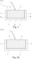
- the sensor 1 comprises a cavity 2 having the shape of a block, defining a bottom surface rectangular 2a and four rectangular surfaces 2b oriented perpendicular to the surface 2a, forming the lateral faces of the cavity.
- the cavity 2 is integrated in a hollow support 7, made for example of an electrically insulating and preferably rigid material, for example a rigid plastic, a ceramic or glass.
- the support 7 can be made of a metallic material, being electrically insulated from the detection structures in contact with it, if any.
- a detection structure 3 is located on each of the surfaces 2a and 2b.
- Cavity 2 is filled with a deformable medium 4, defining a detection surface S on which an external force F is applied.
- the forces generated by the application of the force F are transmitted by the deformable medium 4 to the detection structures 3, which can detect a pressure applied to their respective surface, with an orientation normal to this surface, and corresponding to the transmitted forces.
- the deformable medium 4 can fill the cavity 2 in different ways, and the detection surface can take different shapes.
- the deformable medium 4 fills the cavity 2 so as to come flush with the opening thereof.
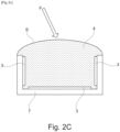
- the deformable medium 4 projects out of the cavity 2, as illustrated in figure 2b .
- the detection surface S is a flat surface, parallel to the bottom surface 2a of the cavity.
- the deformable medium 4 covers the opening of the cavity 2 with a variable thickness, the covering being thicker in the center of the cavity 2, the detection surface S forming a dome above the cavity 2.
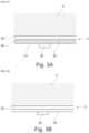
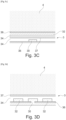
- the detection structure 3 can be realized in different ways, some of which are shown in Figures 3a, 3b , 3c, 3c , 3rd and 3f .
- a first electrode 30 can be printed on a layer of weakly conductive material 31, for example a polymer loaded with carbon particles, and a second electrode 32 can be printed on another layer of weakly conductive material 33.
- the layers 31 and 33 are then superimposed so that the electrodes 30 and 32 are arranged outside the assembly.
- the two layers 31 and 33 are for example separated by a very thin air layer 34, and only touch each other with satisfactory electrical contact when pressure is exerted on the assembly.
- the electrodes 30 and 32 each have a linear shape and are arranged perpendicular to each other.
- the electrode 32 is in contact with the deformable medium 4, while the electrode 30 is in contact with an underlying support (not shown here).
- the forces transmitted by the deformable medium 4 when a force F is applied to the detection surface S vary the contact surface between the layers 31 and 33.
- a voltage is applied between the electrodes 30 and 32, the variation in the contact pressure between the layers 31 and 32 induces a change in the electrical resistance measured in the areas where the electrodes intersect (which correspond to the measurement points).
- the electrodes 30 and 32 are printed on either side of the same layer of intrinsically piezoresistive material 35, which deforms under the action of the forces transmitted by the deformable medium 4, causing similarly to the previous example a variation in the electrical resistivity in the zones of intersection of the electrodes.
- the electrodes are carried by a flexible substrate, for example made of PET.
- the electrodes 30 and 32 are for example printed or each deposited on an electrically insulating flexible layer 36 and face each other, as illustrated in FIG. figure 3c .
- a weakly conductive layer 37 for example of a polymer, possibly cellular, or of a piezoelectric material, is arranged in a sandwich between the electrodes 30 and 32 and separated from each electrode 30 or 32 by a thin air layer 34.
- the electrodes 30 and 32 are carried by the same electrically insulating substrate 36, opposite a weakly conductive layer 37, for example a foam or a non-cellular material, in contact with the deformable medium 4.
- the electrodes are separated from the layer 37 by a thin air layer 34. During a force transmitted by the deformable medium 4, the layer 37 can come into contact with a portion of the electrodes.
- measuring the variation in electrical resistance between two electrodes of such detection structures 3 makes it possible to estimate the forces transmitted by the deformable medium.
- the pressure generated by the forces transmitted to the detection structures 3 can be measured if necessary with discrete sensors.
- the detection structure 3 comprises strain gauges 36, for example of the metallic type, arranged on the surface of the cavity and extending within the deformable medium 4.
- strain gauges 36 are at least partially integrated into the support 7 and come partially into contact with the deformable medium 4.
- Other types of strain sensors can also be used, for example pressure sensors of the Micro Electro-Mechanical System (MEMS) type.
- MEMS Micro Electro-Mechanical System
- the detection structures 3 can be multi-point or single-point measurement. We have illustrated in figure 4 the measurement areas 5 obtained on the surfaces of the cavity of a sensor comprising multipoint detection structures.
- the detection structure 3 arranged on the bottom surface 2a of the cavity 2 defines a grid of 12x12 measurement areas 5.
- the detection structure 3 defines a row of measurement zones 5.
- the number and distribution of the measurement zones 5 on the detection structures 3 is of course not limited to the example illustrated; any arrangement is possible, depending on the nature and arrangement of the detection means with which the detection structure is equipped.
- each detection structure 3 comprises, as previously described, two layers 31 and 33 of weakly electrically conductive material, on which, for example, a plurality of linear and parallel electrodes, spaced regularly, have been printed or deposited by screen printing.
- the electrodes 32 of the layers 33 are visible.
- Electrodes 30 are arranged on the non-visible face of the layers 31 and arranged for example perpendicular to those of the layer 33.
- the layers 31 and 33 thus arranged are integrated into the cavity 2 of the support 7.
- the deformable medium 4 is subsequently added which comes into contact with the layers 33.
- the electrodes printed on the layer 33 of the lateral surfaces 2b of the cavity are vertical in the illustrated embodiment, but any other orientation is possible, for example horizontal or oblique, the electrodes being able to have a U or V shape, for example.
- electrodes 30 and 32 of linear shape are arranged on layers of weakly conductive material 31 and 33, respectively, which will then be assembled one on top of the other so that the electrodes 30 and 32 are located on the outside of the assembly.
- the four-armed cross shape 50 of the layers 31 and 33 represents the flattened cubic cavity. All the electrodes are printed in the same plane, then the assembly is folded at right angles to the central square 51 of the cross for its installation in the hollow support 7. Thus, the detection structures 3 of all the surfaces of the cavity 2 are integrated into the support in a single block, the central square 51 of the cross forming the detection structure of the bottom surface 2a and the arms 52 of the cross each forming the detection structure 3 of a lateral surface 2b of the cavity.
- the arrangement of the electrodes is such that on each detection structure, the electrodes 30 intersect the electrodes 32 perpendicularly, each intersection corresponding to a measurement zone 5. All the electrodes 30 and 32 emerge on the upper part of the cavity.
- the electrodes On two opposite branches 52 of each layer, the electrodes have a U shape, with branches 300 or 320 which extend to the free edge 53 of the branch in order to facilitate electrical connection to a reading circuit.
- the sensor 1 comprises a plurality of unit detection cells 6 comprising only single-point measurement detection structures 3.
- a unit detection cell 6 comprises for example a cubic unit cavity 2, as illustrated in figure 8 , and has five distinct measurement zones 5, one per detection structure 3.
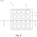
- the support is preferably rigid, and can be formed from a monolithic block, as in the example considered, or as a variant obtained by assembling separate elements.
- the deformable medium 4 of the sensor 1 thus obtained preferably forms a monolithic block as shown in the figure 10 , defining a detection surface S common to all the assembled unit detection cells 6.
- the advantage of such a sensor is to be able to measure a continuous distribution of the forces exerted on the detection surface S.
- a matrix 9 of unit detection cells it is possible with a matrix 9 of unit detection cells to distinguish the application of two separate simultaneous forces.
- a unitary detection cell 6 can be produced by integrating into the cavity 2 two layers 31 and 33 of weakly conductive material in the shape of a cross 50, similarly to what has been described previously.
- single-point detection structures 3 for example three electrodes 30 are printed on the layer 31, and three electrodes 32 on the layer 33.
- the arrangement of the electrodes is such that once all of the two layers are assembled in the cavity, an electrode 30 perpendicularly intersects an electrode 32 on each unitary detection structure 3, corresponding to the single measurement zone 5.
- all of the electrodes 30 and 32 emerge on the upper part of the cavity, and the electrodes located on two opposite branches 52 of the cross have a U shape, with branches 300 or 320 which extend to the free edge 53 of the branch
- the detection structures of a row of unit detection cells 6 of a matrix 9 can be formed in a “strip” on the same substrate, in particular on a flat substrate.
- the strip is subsequently folded to be integrated into the support 7 in a crenellated shape matching the succession of cavities.
- the force sensor according to the invention preferably comprises and as illustrated in the figure 12 a processing circuit 8 for processing the signals delivered by the detection structures 3 to measure at least one, and preferably all, of the components of a force exerted on the detection surface S. It comprises, for example, a central unit 80 and a memory 81.
- the components of the force exerted on the detection surface S can be determined from the processed signals by following, for example, the steps of the method shown in figure 13 and described below.
- a sensor having a cavity in the shape of a block as illustrated in figure 6 , and comprising on each of the surfaces of its cavity a multipoint 3 detection structure defining a grid of measurement zones similar to that shown in the figure 4 .
- the measurement zones 5 are square in shape and all have the same surface area, as illustrated in figure 12 .
- the voltage is sequentially measured on each measurement zone 5 of each detection structure 3.
- v ij the voltage measured in the measurement zone (i,j) located at the intersection of row i with column j of the grid, i and j being integers varying from 1 to the number of rows and columns of the grid, respectively.
- step 12 for example, the three components of the force F exerted on the detection surface S of the sensor 1 are calculated.
- Z designating a direction normal to the detection surface S and to the surface of the bottom of the cavity
- X and Y designating the tangential directions, as illustrated in figure 15 .
- the normal component F z of the force F that is to say the force in the Z direction, is simply given by the resultant of the normal forces F N exerted on the detection structure at the bottom of the cavity 2a.
- a force exerted on the sensor in a normal direction i.e. in the example considered in the Z direction
- forces transmitted 40 in all directions and in particular induce non-zero pressure measurements on the lateral detection structures.
- This phenomenon illustrated in figure 15 , needs to be taken into account for the calculation of the tangential components F x and F y of the force F. It is possible to estimate and subsequently compensate for these tangential pressure measurements by modeling the response of the deformable medium 4 to a normal force, for example according to a Gaussian type model. Examples of such modeling are illustrated in Figures 16a And 16b .
- the forces 40 measured on the 2 opposite lateral surfaces of the sensor are similar. Otherwise and as illustrated in the figure 17 , the forces 40 are greater on one lateral surface than on the other, making it possible to determine the direction of the force F in the corresponding direction.
- the tangential component F y can be calculated using a similar method.
- the moment C of the force F exerted on the sensor 1 can be determined in step 13 from pressure distributions detected by sensing structures on opposite surfaces of the cavity.
- the distribution of the forces 40 exerted on the lateral surfaces of the cavity when a normal force of positive moment is applied to the center of the sensor and similarly, to the figure 18b , the distribution of efforts 40 when a positive moment force is applied to the same point.
- ⁇ is a factor depending on the nature of the deformable medium 4 and the dimensions of the sensor.
- the set of parameters ( ⁇ , ⁇ , ⁇ , ⁇ ) can be determined during a calibration phase during which the sensor is subjected to known stresses, which are compared to the measured forces. Calibration can be carried out in several ways. For example, a model such as a linear or nonlinear regression can be used to find the parameters that minimize an error criterion between the measurement and the model, the error criterion being for example chosen according to the known methods of Mean Square Error (MSE), Root Mean Square Error (RMSE), Mean Absolute Error (MAE), or other.
- MSE Mean Square Error
- RMSE Root Mean Square Error
- MAE Mean Absolute Error
- the method for determining the components of a force exerted on the sensor is not limited to the model that has just been described, in particular if the detection surface of the sensor is of a relatively complex shape.
- a pre-trained neural network can be used to obtain the force applied to the detection surface and determined as a function of the signals detected by the detection structures.
- the training of the neural network takes place beforehand during a calibration phase, as shown in step 19 of the figure 19 where, similarly to the model previously described, the forces exerted on the detection structures when the sensor is subjected to known stresses are measured, in order to provide the neural network with examples for its training.
- the neural network Once the neural network is trained for a given sensor, it can be used in step 20 to determine all kinds of forces exerted on its detection surface.
- other machine learning algorithms can be used, such as the Support Vector Machine (SVR), GradientBoosting, or Random forest methods.
- a single processing circuit 8 can for example process all of the signals of the matrix 9 in order for example to calculate the distribution of the force(s) exerted on the detection surface S of the device, and/or the moment corresponding to said forces.
- This method is illustrated in figure 20 .
- the voltage on the single measurement zone 5 of each detection structure 3 is measured.
- the pressure exerted on the detection structure 5 is estimated as a function of the measured voltage and the components of the force exerted on the unit detection cells 6 are calculated using the same method as described previously, with or without compensation for the tangential pressures due to a normal force.
- step 17 a distribution of forces over the entire matrix 9 is advantageously obtained from the calculated forces, which can provide new information on the nature of the forces exerted on the sensor.
- the senor comprises 3-point multi-point detection structures having a matrix arrangement of the electrodes resulting in a grid of measurement zones as for example illustrated in figure 4
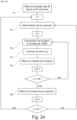
- a method of reading the measurement zones 5 by scanning can be implemented such as that shown in figure 24 .
- This process described below, uses a method similar to that proposed in the article " The UnMousePad - An Interpolating Multi-Touch Force-Sensing Input Pad” by Rosenberg et. A1 (ACM SIGGRAPH 2009 papers. 2009. 1-9 ).
- This method of sequential reading by feeding each of the measurement zones 5 in turn as illustrated in the figure 25 , while connecting the other electrodes to ground (not shown in the figure 25 ), advantageously limits measurement artifacts, such as "ghost" signals, linked to current leakage paths within the detection structure.
- the electronic components thanks to channel multiplexing, can also be shared, which can reduce the manufacturing cost of the sensor.
- several analog/digital converters can be used with or without channel multiplexing, in particular one converter per electrode j connected to the reading circuit.
- a sensor according to the invention can be manufactured by following for example the steps of the method illustrated in figure 26 .
- step 21 at least one first electrode 30 having, for example, a linear shape is printed on a first layer of weakly conductive material 31.
- step 22 at least one second electrode 32, in particular similar to the first electrode, is printed on a second layer 33 of weakly conductive material.
- step 23 the layers 31 and 33 are assembled so that the electrodes 30 and 32 are on the outer faces of the assembly and the electrode 32 crosses, in front view, the electrode 30.
- the assembly obtained is then cut into a shape corresponding to the pattern of the cavity 2, before being integrated in step 24 into the support 7, a detection structure 3 thus being found on each surface of the cavity.
- step 25 the cavity is at least partially filled with an elastically deformable material, in particular an elastomer, and each electrode of the sensor thus obtained is electrically connected in step 26; the latter may take place before step 25 if necessary.
- the detection of the pressures exerted on the detection structures 3 is not necessarily obtained by resistive measurement. It can for example be done by capacitive measurement, for example by replacing the conductive material with a material with a high dielectric constant, and by subjecting for example the measurement electrodes to alternating voltages, or any other method suitable for measuring a capacitance.
- the cavity can be of any shape, and of any depth according to the needs. For example, it can be very shallow.
- the dimensions of the corresponding sensor can vary for example from a few millimeters to a few centimeters in width and length, and the thickness is for example a few millimeters.
- the sensor may further be equipped to measure other quantities in addition to the force exerted on its detection surface.
- it may include measuring means for estimating the temperature of an object exerting a force on its detection surface, in particular by means of a temperature sensor under the bottom surface of the cavity.
- a piezoelectric layer may be added in order to measure possible vibrations or accelerations.
- the sensor according to the invention can be used, among other things, for robotic applications, in particular in the context of the right-handed robotic manipulation of objects. For example, it makes it possible to improve the qualities of manipulation of objects by robots, in particular to detect and identify the sliding of these objects.
- the senor is integrated into a human-machine touch interface.
Landscapes
- Engineering & Computer Science (AREA)
- General Engineering & Computer Science (AREA)
- Theoretical Computer Science (AREA)
- Physics & Mathematics (AREA)
- General Physics & Mathematics (AREA)
- Human Computer Interaction (AREA)
- Power Engineering (AREA)
- Force Measurement Appropriate To Specific Purposes (AREA)
Claims (16)
- Kraftsensor (1), umfassend:o mindestens einen Hohlraum (2), der durch einen hohlen starren Träger (7) definiert wird, wobei der Hohlraum mindestens zwei Hohlraumoberflächen (2a, 2b), aufweisend unterschiedliche Orientierungen, definiert, wobei der Hohlraum (2) vorzugsweise die Form eines Polyeders, insbesondere eines Blocks, aufweisto auf jeder der Hohlraumoberflächen (2a, 2b) mindestens eine jeweilige Erfassungsstruktur (3), die von dem hohlen starren Träger (7) getragen wird und auf einen Druck anspricht, der auf die entsprechende Messoberfläche ausgeübt wird, wobei mindestens eine der Erfassungsstrukturen (3) vorzugsweise piezoresistive oder kapazitive, vorzugsweise piezoresistive Erfassungsmittel umfasst, undo ein elastisch verformbares Medium (4), das den Hohlraum (2) mindestens teilweise ausfüllt, indem es mit den Messoberflächen in Kontakt kommt und eine Erfassungsoberfläche (S) definiert, auf die eine zu erfassende Kraft ausgeübt werden kann, wobei die Anwendung dieser Kraft aufgrund der Übertragung der Kräfte durch das Medium (4) Spannungen (40) auf jeder Erfassungsstruktur (3) verursachen kann.
- Sensor nach Anspruch 1, wobei das elastisch verformbare Medium (4) den Hohlraum (2) so ausfüllt, dass es bündig mit dessen Öffnung abschließt und/oder sich aus dem Hohlraum heraus erstreckt.
- Sensor nach einem der vorhergehenden Ansprüche, wobei die durch das elastisch verformbare Medium definierte Erfassungsoberfläche (S) eine nach außen konvexe Form, insbesondere eine Kuppelform, annimmt.
- Sensor nach einem der vorhergehenden Ansprüche, wobei mindestens eine der Erfassungsstrukturen (3) mit mehreren Messpunkten oder mit einem Messpunkt ausgebildet ist.
- Sensor nach einem der vorhergehenden Ansprüche, wobei mindestens eine der Erfassungsstrukturen (3), und insbesondere jede Erfassungsstruktur (3), umfasst:o mindestens eine erste Elektrode (30), die auf der Seite der Erfassungsstruktur auf Höhe eines darunter liegenden Trägers (7) angeordnet ist, insbesondere in Kontakt mit diesem, undo mindestens eine zweite Elektrode (32), die auf der Seite der Erfassungsstruktur auf Höhe des elastisch verformbaren Mediums (4) angeordnet ist, insbesondere in Kontakt mit diesem, wobei sich die erste und die zweite Elektrode vorzugsweise mindestens teilweise überlagern, wobei die erste und die zweite Elektrode insbesondere jeweils eine lineare Form aufweisen.
- Sensor nach einem der vorhergehenden Ansprüche, wobei mindestens eine der Erfassungsstrukturen (3), besser jede von ihnen, umfasst:o eine Vielzahl erster Elektroden (30), die auf der Seite der Erfassungsstruktur auf Höhe eines darunter liegenden Trägers (7) angeordnet sind, insbesondere in Kontakt mit diesem, undo eine Vielzahl zweiter Elektroden (32), die auf der Seite der Erfassungsstruktur auf Höhe des elastisch verformbaren Mediums (4) angeordnet sind, insbesondere in Kontakt mit diesem.
- Sensor nach Anspruch 6, wobei die ersten Elektroden beabstandete parallele Abschnitte umfassen und die zweiten Elektroden beabstandete parallele Abschnitte umfassen, die die ersten Abschnitte kreuzen, wenn sie entlang der Achse senkrecht zu der Ebene gesehen werden, die durch die ersten Abschnitte definiert wird, insbesondere senkrecht zu ihnen.
- Sensor nach einem der Ansprüche 5 bis 7, wobei die erste oder ersten Elektroden (30) auf eine erste Schicht aus schwach leitendem Material (31) gedruckt sind, die zweite oder zweiten Elektroden (32) auf eine zweite Schicht aus schwach leitendem Material (33) gedruckt sind, wobei die erste und die zweite Schicht anschließend so zusammengesetzt werden, dass sich die Elektroden auf den Außenseiten der Anordnung befinden.
- Sensor nach einem der vorhergehenden Ansprüche, ferner umfassend eine Schaltung zur Verarbeitung (8) von Signalen, die von den Erfassungsstrukturen (3) bereitgestellt werden und die Drücke darstellen, die auf diese Strukturen durch die auf die Erfassungsoberfläche (S) wirkende Kraft induziert werden, und die so konfiguriert ist, dass sie diese verarbeitet, um mindestens eine Komponente der Kraft zu berechnen.
- Sensor nach dem vorhergehenden Anspruch, wobei die Verarbeitungsschaltung (8) so konfiguriert ist, dass sie eine Druckverteilung über mindestens eine der Erfassungsstrukturen (3) misst.
- Sensor nach einem der Ansprüche 9 oder 10, wobei die Verarbeitungsschaltung (8) so konfiguriert ist, dass sie mindestens eine Komponente des Moments der auf die Erfassungsoberfläche (S) wirkenden Kraft aus Druckverteilungen misst, die von Erfassungsstrukturen erfasst werden, die auf gegenüberliegenden Oberflächen (2b) des Hohlraums vorhanden sind.
- Sensor nach einem der vorhergehenden Ansprüche, umfassend eine Vielzahl von einzelnen Erfassungszellen (6), die jeweils aus einem einzelnen Hohlraum (2) gebildet sind, der nur mit Einpunkt-Erfassungsstrukturen (3) ausgestattet ist, wobei sich das verformbare Medium (4) vorzugsweise in jeden der einzelnen Hohlräume (2) erstreckt und eine Erfassungsoberfläche (S) definiert, auf die eine zu erfassende Kraft einwirken kann.
- Sensor nach einem der vorhergehenden Ansprüche, wobei die Verarbeitungsschaltung (8) so konfiguriert ist, dass sie mindestens eine Komponente einer einzelnen Kraft, die auf eine einzelne Erfassungszelle (6) wirken kann, anhand der Drücke misst, die von den Einpunkt-Erfassungsstrukturen (3) der Erfassungszelle (6) erfasst werden, wobei die Verarbeitungsschaltung (8) vorzugsweise so konfiguriert ist, dass sie die Verteilung mindestens einer Komponente mindestens einer Kraft misst, die auf die Erfassungsoberfläche (S) des Sensors ausgehend von der Kenntnis der auf die Erfassungszellen (6) wirkenden einzelnen Kräfte ausgeübt werden kann.
- Verfahren zum Messen mindestens einer Komponente einer Kraft, die auf die Erfassungsoberfläche (S) eines Sensors (1), wie in einem der Ansprüche 1 bis 13 definiert, ausgeübt wird, umfassend die folgenden Schritte:o Messen von elektrischen Störungen, die durch Spannungen (40) induziert werden, die auf die Messzone(n) (5) der Erfassungsstrukturen des Sensors aufgrund der Übertragung von Kräften des elastisch verformbaren Mediums (4), das die Erfassungsoberfläche (3) definiert, ausgeübt werden,o Berechnen aus den so gemessenen Störungen mindestens einer Komponente der auf den Sensor ausgeübten Kraft.
- Verfahren nach dem vorhergehenden Anspruch, wenn der Sensor (1) durch einen der Ansprüche 5 bis 8 definiert ist, wobei mindestens eine der Erfassungsstrukturen (3) mehrpunktförmig ist, wobei in dem Verfahren eine Druckverteilung auf der Erfassungsstruktur (3) gemessen wird, und vorzugsweise bei dem mindestens eine Komponente des Moments der ausgeübten Kraft aus der Messung der Druckfelder auf Erfassungsstrukturen (3), die auf gegenüberliegenden Oberflächen (2b) des Hohlraums (2) vorhanden sind, berechnet wird und/oder vorzugsweise bei dem die auf die Erfassungsoberfläche (S) ausgeübte Kraft in Abhängigkeit von den Signalen, die von den Erfassungsstrukturen (3) erfasst werden, mittels eines trainierten neuronalen Netzes ermittelt wird und/oder vorzugsweise bei dem die erfassten Störungen an allen Messpunkten (5) einer Erfassungsstruktur (3), die ein Matrixmuster der Elektroden mit Zeilenelektroden (32) und Spaltenelektroden (30) annimmt, ausgelesen werden, wobei M die Anzahl der Zeilen und N die Anzahl der Spalten bezeichnet, wobei die Kreuzung der Elektroden Messpunkte (5) definiert, das Verfahren umfassend die folgenden Schritte:o Anlegen aller Elektroden (30, 32) an die Masse undo Wiederholen für die ganze Zahl i, die zwischen 1 und N umfasst ist:- Versorgen der Elektrode i und- Wiederholen für die ganze Zahl j, die zwischen 1 und M umfasst ist:o Verbinden der Elektrode j mit dem Eingang einer Ableseschaltung,o Auslesen des Signals an dem Messpunkt (5), der dem Schnittpunkt der Elektroden i und j entspricht, undo Anlegen der Elektrode j an die Masse und- Anlegen der Elektrode i an die Masse.
- Verfahren zur Herstellung eines Kraftsensors (1), wie in einem der Ansprüche 1 bis 13 definiert, wobei:o auf eine erste Schicht aus elektrisch schwach leitendem Material (31) mindestens eine erste Elektrode (30) gedruckt wird, die eine lineare Form annimmt,o auf eine zweite Schicht aus elektrisch schwach leitendem Material (33) mindestens eine zweite Elektrode (32) gedruckt wird, die eine lineare Form annimmt,o die erste und die zweite Schicht (31, 33) so zusammengesetzt werden, dass sich die Elektroden (30, 32) auf den Außenseiten der Anordnung befinden und die zweite Elektrode (32) die erste Elektrode (30) kreuzt, wenn man sie entlang der Achse senkrecht zu der von der ersten Elektrode (30) definierten Ebene betrachtet,o die so erhaltene Anordnung in einen ausgehöhlten Träger (7) integriert wird, wobei die Anordnung die Seiten eines Hohlraums definiert,o der Hohlraum mindestens teilweise mit einem elastisch verformbaren Material (4), insbesondere einem Elastomer, ausgefüllt wird.
Applications Claiming Priority (1)
| Application Number | Priority Date | Filing Date | Title |
|---|---|---|---|
| FR2013360A FR3117592B1 (fr) | 2020-12-16 | 2020-12-16 | Capteur de force |
Publications (2)
| Publication Number | Publication Date |
|---|---|
| EP4016026A1 EP4016026A1 (de) | 2022-06-22 |
| EP4016026B1 true EP4016026B1 (de) | 2024-11-27 |
Family
ID=74554086
Family Applications (1)
| Application Number | Title | Priority Date | Filing Date |
|---|---|---|---|
| EP21214849.8A Active EP4016026B1 (de) | 2020-12-16 | 2021-12-15 | Kraftaufnehmer |
Country Status (3)
| Country | Link |
|---|---|
| US (1) | US12189882B2 (de) |
| EP (1) | EP4016026B1 (de) |
| FR (1) | FR3117592B1 (de) |
Families Citing this family (3)
| Publication number | Priority date | Publication date | Assignee | Title |
|---|---|---|---|---|
| CN111351615B (zh) * | 2020-03-25 | 2021-07-20 | 东南大学 | 空间站机械臂六维力传感器高精度小型化在轨标定装置及标定方法 |
| US11835401B2 (en) * | 2022-08-26 | 2023-12-05 | Mike Horia Mihail Teodorescu | Sensors for pressure, forces, and couples |
| JP2024048624A (ja) * | 2022-09-28 | 2024-04-09 | セイコーエプソン株式会社 | 感圧センサー、把持装置およびロボット |
Family Cites Families (11)
| Publication number | Priority date | Publication date | Assignee | Title |
|---|---|---|---|---|
| ATE409310T1 (de) | 2001-07-10 | 2008-10-15 | Michelin Soc Tech | Eine messeinrichtung beinhaltender reifen |
| JP2006305658A (ja) * | 2005-04-27 | 2006-11-09 | Sharp Corp | ロボットフィンガ |
| EP1969332A2 (de) * | 2006-10-18 | 2008-09-17 | Plastic Electronic GmbH | Messvorrichtung |
| US8272278B2 (en) | 2007-03-28 | 2012-09-25 | University Of Southern California | Enhancements to improve the function of a biomimetic tactile sensor |
| JP5416904B2 (ja) * | 2008-02-12 | 2014-02-12 | 株式会社東芝 | 圧力センサおよびロボットハンドシステム |
| EP2247998B1 (de) * | 2008-02-28 | 2019-04-10 | New York University | Verfahren und vorrichtung zur bereitstellung von eingaben in einen prozessor und sensor-pad |
| JP5449336B2 (ja) | 2008-06-19 | 2014-03-19 | マサチューセッツ インスティテュート オブ テクノロジー | 弾性撮像を使用する接触センサ |
| US9372588B2 (en) | 2011-05-19 | 2016-06-21 | Microsoft Technology Licensing, Llc | Pressure-sensitive multi-touch device |
| US10067019B2 (en) | 2016-01-25 | 2018-09-04 | Ati Industrial Automation, Inc. | Force and torque sensor having redundant instrumentation and operative to detect faults |
| US10481747B2 (en) * | 2016-09-09 | 2019-11-19 | Sensel Inc. | System for detecting and characterizing inputs on a touch sensor |
| JP7193262B2 (ja) | 2018-07-23 | 2022-12-20 | ミネベアミツミ株式会社 | 触覚センサ |
-
2020
- 2020-12-16 FR FR2013360A patent/FR3117592B1/fr active Active
-
2021
- 2021-12-14 US US17/644,118 patent/US12189882B2/en active Active
- 2021-12-15 EP EP21214849.8A patent/EP4016026B1/de active Active
Also Published As
| Publication number | Publication date |
|---|---|
| US12189882B2 (en) | 2025-01-07 |
| FR3117592A1 (fr) | 2022-06-17 |
| FR3117592B1 (fr) | 2022-12-16 |
| US20220187971A1 (en) | 2022-06-16 |
| EP4016026A1 (de) | 2022-06-22 |
Similar Documents
| Publication | Publication Date | Title |
|---|---|---|
| EP4016026A1 (de) | Kraftaufnehmer | |
| EP3169983B1 (de) | System mit einem zellularen netzwerk aus kapazitiven druck- und scherbelastungssensoren und herstellungsverfahren | |
| EP1614023B8 (de) | Positionsdetektionseinrichtung | |
| EP4006698B1 (de) | Haptische schnittstelle | |
| EP3556017B1 (de) | Vorrichtung und verfahren zur erfassung der annäherung und/oder berührung und des drucks eines objekts in bezug auf eine erfassungsfläche | |
| FR2916545A1 (fr) | Procede pour localiser un toucher sur une surface et dispositif pour la mise en oeuvre de ce procede. | |
| WO2010092092A1 (fr) | Capteur de force de contact | |
| WO2013144342A2 (fr) | Procede et dispositif de localisation d'un objet magnetique | |
| FR2942658A1 (fr) | Peau protectrice pour robots | |
| FR3066030B1 (fr) | Procede et dispositif de generation de motifs tactiles | |
| EP1923662A2 (de) | Verfahren und Vorrichtung zur Erfassung einer verformbaren geometrischen Form | |
| EP4123281A1 (de) | Matrixdrucksensor mit neuronalem netzwerk und entsprechendes kalibrierungsverfahren | |
| EP2831705A2 (de) | Bildschirm mit magnetischer objektfindung | |
| FR2883073A1 (fr) | Procede et dispositif d'acquisition d'une forme geometrique. | |
| FR2988874A1 (fr) | Procede de detection d'un point de contact entre une pointe d'un ustensile et un support d'ecriture | |
| EP4062536A1 (de) | Näherungs- und druckdetektor, detektionsschicht und mit solchen vorrichtungen ausgestattete ausrüstung | |
| EP4060461B1 (de) | Flexible haptische schnittstelle | |
| WO2017097720A1 (fr) | Systeme de detection d'efforts ou de deformations, en particulier pour une peau tactile | |
| FR3001800A1 (fr) | Capteur de pression capacitif souple | |
| WO2015082844A1 (fr) | Systeme de determination de la forme au moins partielle d'un objet tridimentionnel et procede correspondant | |
| EP3335021B1 (de) | Kraftsensor | |
| EP1519164B1 (de) | Wägeeinrichtung | |
| FR3003029A1 (fr) | Capteur capacitif de contrainte mecanique, ensemble de capteurs et dispositif de localisation de toucher a capteurs capacitifs | |
| WO2012120225A1 (fr) | Procede de fabrication d'un film transparent, notamment pour un capteur tactile matriciel transparent | |
| WO2007034078A1 (fr) | Dispositif d'acquisition de mesure de la pression de pas de personnes |
Legal Events
| Date | Code | Title | Description |
|---|---|---|---|
| PUAI | Public reference made under article 153(3) epc to a published international application that has entered the european phase |
Free format text: ORIGINAL CODE: 0009012 |
|
| STAA | Information on the status of an ep patent application or granted ep patent |
Free format text: STATUS: REQUEST FOR EXAMINATION WAS MADE |
|
| 17P | Request for examination filed |
Effective date: 20211215 |
|
| AK | Designated contracting states |
Kind code of ref document: A1 Designated state(s): AL AT BE BG CH CY CZ DE DK EE ES FI FR GB GR HR HU IE IS IT LI LT LU LV MC MK MT NL NO PL PT RO RS SE SI SK SM TR |
|
| GRAP | Despatch of communication of intention to grant a patent |
Free format text: ORIGINAL CODE: EPIDOSNIGR1 |
|
| STAA | Information on the status of an ep patent application or granted ep patent |
Free format text: STATUS: GRANT OF PATENT IS INTENDED |
|
| INTG | Intention to grant announced |
Effective date: 20240704 |
|
| GRAS | Grant fee paid |
Free format text: ORIGINAL CODE: EPIDOSNIGR3 |
|
| GRAA | (expected) grant |
Free format text: ORIGINAL CODE: 0009210 |
|
| STAA | Information on the status of an ep patent application or granted ep patent |
Free format text: STATUS: THE PATENT HAS BEEN GRANTED |
|
| RAP3 | Party data changed (applicant data changed or rights of an application transferred) |
Owner name: COMMISSARIAT A L'ENERGIE ATOMIQUE ET AUX ENERGIESALTERNATIVES |
|
| AK | Designated contracting states |
Kind code of ref document: B1 Designated state(s): AL AT BE BG CH CY CZ DE DK EE ES FI FR GB GR HR HU IE IS IT LI LT LU LV MC MK MT NL NO PL PT RO RS SE SI SK SM TR |
|
| REG | Reference to a national code |
Ref country code: GB Ref legal event code: FG4D Free format text: NOT ENGLISH |
|
| REG | Reference to a national code |
Ref country code: CH Ref legal event code: EP |
|
| REG | Reference to a national code |
Ref country code: IE Ref legal event code: FG4D Free format text: LANGUAGE OF EP DOCUMENT: FRENCH |
|
| REG | Reference to a national code |
Ref country code: DE Ref legal event code: R096 Ref document number: 602021022354 Country of ref document: DE |
|
| REG | Reference to a national code |
Ref country code: LT Ref legal event code: MG9D |
|
| REG | Reference to a national code |
Ref country code: NL Ref legal event code: MP Effective date: 20241127 |
|
| PG25 | Lapsed in a contracting state [announced via postgrant information from national office to epo] |
Ref country code: PT Free format text: LAPSE BECAUSE OF FAILURE TO SUBMIT A TRANSLATION OF THE DESCRIPTION OR TO PAY THE FEE WITHIN THE PRESCRIBED TIME-LIMIT Effective date: 20250327 Ref country code: HR Free format text: LAPSE BECAUSE OF FAILURE TO SUBMIT A TRANSLATION OF THE DESCRIPTION OR TO PAY THE FEE WITHIN THE PRESCRIBED TIME-LIMIT Effective date: 20241127 Ref country code: IS Free format text: LAPSE BECAUSE OF FAILURE TO SUBMIT A TRANSLATION OF THE DESCRIPTION OR TO PAY THE FEE WITHIN THE PRESCRIBED TIME-LIMIT Effective date: 20250327 |
|
| PGFP | Annual fee paid to national office [announced via postgrant information from national office to epo] |
Ref country code: DE Payment date: 20250319 Year of fee payment: 4 |
|
| PG25 | Lapsed in a contracting state [announced via postgrant information from national office to epo] |
Ref country code: FI Free format text: LAPSE BECAUSE OF FAILURE TO SUBMIT A TRANSLATION OF THE DESCRIPTION OR TO PAY THE FEE WITHIN THE PRESCRIBED TIME-LIMIT Effective date: 20241127 Ref country code: NL Free format text: LAPSE BECAUSE OF FAILURE TO SUBMIT A TRANSLATION OF THE DESCRIPTION OR TO PAY THE FEE WITHIN THE PRESCRIBED TIME-LIMIT Effective date: 20241127 |
|
| REG | Reference to a national code |
Ref country code: AT Ref legal event code: MK05 Ref document number: 1746088 Country of ref document: AT Kind code of ref document: T Effective date: 20241127 |
|
| PG25 | Lapsed in a contracting state [announced via postgrant information from national office to epo] |
Ref country code: BG Free format text: LAPSE BECAUSE OF FAILURE TO SUBMIT A TRANSLATION OF THE DESCRIPTION OR TO PAY THE FEE WITHIN THE PRESCRIBED TIME-LIMIT Effective date: 20241127 |
|
| PG25 | Lapsed in a contracting state [announced via postgrant information from national office to epo] |
Ref country code: ES Free format text: LAPSE BECAUSE OF FAILURE TO SUBMIT A TRANSLATION OF THE DESCRIPTION OR TO PAY THE FEE WITHIN THE PRESCRIBED TIME-LIMIT Effective date: 20241127 |
|
| PG25 | Lapsed in a contracting state [announced via postgrant information from national office to epo] |
Ref country code: NO Free format text: LAPSE BECAUSE OF FAILURE TO SUBMIT A TRANSLATION OF THE DESCRIPTION OR TO PAY THE FEE WITHIN THE PRESCRIBED TIME-LIMIT Effective date: 20250227 |
|
| PG25 | Lapsed in a contracting state [announced via postgrant information from national office to epo] |
Ref country code: GR Free format text: LAPSE BECAUSE OF FAILURE TO SUBMIT A TRANSLATION OF THE DESCRIPTION OR TO PAY THE FEE WITHIN THE PRESCRIBED TIME-LIMIT Effective date: 20250228 Ref country code: LV Free format text: LAPSE BECAUSE OF FAILURE TO SUBMIT A TRANSLATION OF THE DESCRIPTION OR TO PAY THE FEE WITHIN THE PRESCRIBED TIME-LIMIT Effective date: 20241127 Ref country code: AT Free format text: LAPSE BECAUSE OF FAILURE TO SUBMIT A TRANSLATION OF THE DESCRIPTION OR TO PAY THE FEE WITHIN THE PRESCRIBED TIME-LIMIT Effective date: 20241127 |
|
| PG25 | Lapsed in a contracting state [announced via postgrant information from national office to epo] |
Ref country code: PL Free format text: LAPSE BECAUSE OF FAILURE TO SUBMIT A TRANSLATION OF THE DESCRIPTION OR TO PAY THE FEE WITHIN THE PRESCRIBED TIME-LIMIT Effective date: 20241127 |
|
| PG25 | Lapsed in a contracting state [announced via postgrant information from national office to epo] |
Ref country code: RS Free format text: LAPSE BECAUSE OF FAILURE TO SUBMIT A TRANSLATION OF THE DESCRIPTION OR TO PAY THE FEE WITHIN THE PRESCRIBED TIME-LIMIT Effective date: 20250227 |
|
| PG25 | Lapsed in a contracting state [announced via postgrant information from national office to epo] |
Ref country code: SM Free format text: LAPSE BECAUSE OF FAILURE TO SUBMIT A TRANSLATION OF THE DESCRIPTION OR TO PAY THE FEE WITHIN THE PRESCRIBED TIME-LIMIT Effective date: 20241127 |
|
| PG25 | Lapsed in a contracting state [announced via postgrant information from national office to epo] |
Ref country code: DK Free format text: LAPSE BECAUSE OF FAILURE TO SUBMIT A TRANSLATION OF THE DESCRIPTION OR TO PAY THE FEE WITHIN THE PRESCRIBED TIME-LIMIT Effective date: 20241127 |
|
| PG25 | Lapsed in a contracting state [announced via postgrant information from national office to epo] |
Ref country code: EE Free format text: LAPSE BECAUSE OF FAILURE TO SUBMIT A TRANSLATION OF THE DESCRIPTION OR TO PAY THE FEE WITHIN THE PRESCRIBED TIME-LIMIT Effective date: 20241127 |
|
| PG25 | Lapsed in a contracting state [announced via postgrant information from national office to epo] |
Ref country code: RO Free format text: LAPSE BECAUSE OF FAILURE TO SUBMIT A TRANSLATION OF THE DESCRIPTION OR TO PAY THE FEE WITHIN THE PRESCRIBED TIME-LIMIT Effective date: 20241127 |
|
| PG25 | Lapsed in a contracting state [announced via postgrant information from national office to epo] |
Ref country code: SK Free format text: LAPSE BECAUSE OF FAILURE TO SUBMIT A TRANSLATION OF THE DESCRIPTION OR TO PAY THE FEE WITHIN THE PRESCRIBED TIME-LIMIT Effective date: 20241127 |
|
| PG25 | Lapsed in a contracting state [announced via postgrant information from national office to epo] |
Ref country code: CZ Free format text: LAPSE BECAUSE OF FAILURE TO SUBMIT A TRANSLATION OF THE DESCRIPTION OR TO PAY THE FEE WITHIN THE PRESCRIBED TIME-LIMIT Effective date: 20241127 |
|
| PG25 | Lapsed in a contracting state [announced via postgrant information from national office to epo] |
Ref country code: IT Free format text: LAPSE BECAUSE OF FAILURE TO SUBMIT A TRANSLATION OF THE DESCRIPTION OR TO PAY THE FEE WITHIN THE PRESCRIBED TIME-LIMIT Effective date: 20241127 |
|
| REG | Reference to a national code |
Ref country code: CH Ref legal event code: PL |
|
| PG25 | Lapsed in a contracting state [announced via postgrant information from national office to epo] |
Ref country code: LU Free format text: LAPSE BECAUSE OF NON-PAYMENT OF DUE FEES Effective date: 20241215 |
|
| REG | Reference to a national code |
Ref country code: DE Ref legal event code: R097 Ref document number: 602021022354 Country of ref document: DE |
|
| PG25 | Lapsed in a contracting state [announced via postgrant information from national office to epo] |
Ref country code: SE Free format text: LAPSE BECAUSE OF FAILURE TO SUBMIT A TRANSLATION OF THE DESCRIPTION OR TO PAY THE FEE WITHIN THE PRESCRIBED TIME-LIMIT Effective date: 20241127 |
|
| PG25 | Lapsed in a contracting state [announced via postgrant information from national office to epo] |
Ref country code: MC Free format text: LAPSE BECAUSE OF FAILURE TO SUBMIT A TRANSLATION OF THE DESCRIPTION OR TO PAY THE FEE WITHIN THE PRESCRIBED TIME-LIMIT Effective date: 20241127 |
|
| PLBE | No opposition filed within time limit |
Free format text: ORIGINAL CODE: 0009261 |
|
| STAA | Information on the status of an ep patent application or granted ep patent |
Free format text: STATUS: NO OPPOSITION FILED WITHIN TIME LIMIT |
|
| REG | Reference to a national code |
Ref country code: BE Ref legal event code: MM Effective date: 20241231 |
|
| PG25 | Lapsed in a contracting state [announced via postgrant information from national office to epo] |
Ref country code: BE Free format text: LAPSE BECAUSE OF NON-PAYMENT OF DUE FEES Effective date: 20241231 |
|
| PG25 | Lapsed in a contracting state [announced via postgrant information from national office to epo] |
Ref country code: CH Free format text: LAPSE BECAUSE OF NON-PAYMENT OF DUE FEES Effective date: 20241231 |
|
| PG25 | Lapsed in a contracting state [announced via postgrant information from national office to epo] |
Ref country code: IE Free format text: LAPSE BECAUSE OF NON-PAYMENT OF DUE FEES Effective date: 20241215 |
|
| 26N | No opposition filed |
Effective date: 20250828 |
|
| PGFP | Annual fee paid to national office [announced via postgrant information from national office to epo] |
Ref country code: FR Payment date: 20251222 Year of fee payment: 5 |
|
| PG25 | Lapsed in a contracting state [announced via postgrant information from national office to epo] |
Ref country code: CY Free format text: LAPSE BECAUSE OF FAILURE TO SUBMIT A TRANSLATION OF THE DESCRIPTION OR TO PAY THE FEE WITHIN THE PRESCRIBED TIME-LIMIT Effective date: 20241127 |