EP4060461B1 - Flexible haptische schnittstelle - Google Patents
Flexible haptische schnittstelle Download PDFInfo
- Publication number
- EP4060461B1 EP4060461B1 EP22162057.8A EP22162057A EP4060461B1 EP 4060461 B1 EP4060461 B1 EP 4060461B1 EP 22162057 A EP22162057 A EP 22162057A EP 4060461 B1 EP4060461 B1 EP 4060461B1
- Authority
- EP
- European Patent Office
- Prior art keywords
- actuators
- interface
- wall
- flexible
- fluid
- Prior art date
- Legal status (The legal status is an assumption and is not a legal conclusion. Google has not performed a legal analysis and makes no representation as to the accuracy of the status listed.)
- Active
Links
Images







Classifications
-
- G—PHYSICS
- G06—COMPUTING OR CALCULATING; COUNTING
- G06F—ELECTRIC DIGITAL DATA PROCESSING
- G06F3/00—Input arrangements for transferring data to be processed into a form capable of being handled by the computer; Output arrangements for transferring data from processing unit to output unit, e.g. interface arrangements
- G06F3/01—Input arrangements or combined input and output arrangements for interaction between user and computer
- G06F3/016—Input arrangements with force or tactile feedback as computer generated output to the user
-
- G—PHYSICS
- G06—COMPUTING OR CALCULATING; COUNTING
- G06F—ELECTRIC DIGITAL DATA PROCESSING
- G06F3/00—Input arrangements for transferring data to be processed into a form capable of being handled by the computer; Output arrangements for transferring data from processing unit to output unit, e.g. interface arrangements
- G06F3/01—Input arrangements or combined input and output arrangements for interaction between user and computer
- G06F3/03—Arrangements for converting the position or the displacement of a member into a coded form
- G06F3/041—Digitisers, e.g. for touch screens or touch pads, characterised by the transducing means
-
- G—PHYSICS
- G06—COMPUTING OR CALCULATING; COUNTING
- G06F—ELECTRIC DIGITAL DATA PROCESSING
- G06F2203/00—Indexing scheme relating to G06F3/00 - G06F3/048
- G06F2203/041—Indexing scheme relating to G06F3/041 - G06F3/045
- G06F2203/04102—Flexible digitiser, i.e. constructional details for allowing the whole digitising part of a device to be flexed or rolled like a sheet of paper
Definitions
- a haptic interface allows the user to interact with the environment through the sense of touch.
- the haptic effect is increasingly used in many applications today, for example on a smartphone, when it generates a slight vibration when a key displayed on the screen is pressed to simulate the impression of pressing a button.
- Haptic applications also exist for virtual or augmented reality devices, particularly to allow better immersion in video games.
- Haptic interfaces such as touchscreens, generating a haptic effect on a touch surface when a user contacts it, can be integrated into many technologies such as computers, tablets and/or smartphones.
- WO2010078597A1 discloses a tactile haptic interface comprising fluid channels and chambers for generating a button effect.
- Lochtefeld's article “Towards real organic user interfaces - using non-Newtonian fluids for self-actuated displays” (CHI13 workshop, 2013) describes a haptic device using a shear-thickening non-Newtonian fluid sandwiched between two flexible sheets placed on a fixed array of loudspeakers.
- a finger-perceptible topology is generated when a sound wave propagates through the fluid and locally hardens it.
- the spatial resolution of the generated haptic effect is, however, relatively low given the bulk of the loudspeakers, and furthermore, such an interface is not completely flexible.
- the tactile surface can be smooth, or have micro-reliefs.
- the inner faces of the walls defining the touch surface and serving as support may be smooth, or have reliefs.
- the walls may have thinnings and/or extra thicknesses, for example to facilitate the mounting of certain elements such as actuators, or to allow the walls to be assembled together, or to create more flexible or, on the contrary, more rigid local areas, particularly at the level of the extra thicknesses.
- the wall defining the touch surface may have a multi-layer structure, in particular when it includes an external detection system and/or a flexible screen.
- the wall may include an inner layer in contact with the fluid, and one or more outer layers to perform detection and/or display functions. These layers may be assembled in various ways, with or without clearance between them, but their arrangement makes it possible to feel through them, over at least part of their extent, the changes made to the rheology of the fluid by the actuators.
- the fluid can be opaque, translucent, or transparent. It can be colored or not. It can be a shear-thickening, shear-thinning, viscoplastic, or any other suitable non-Newtonian fluid. This fluid can be electrically conductive or not.
- the actuators are preferably in contact with the fluid.
- their deformation when actuated allows direct mechanical stress on the fluid.
- this facilitates the integration of small actuators, which is advantageous for giving the interface the desired flexibility. It can also make it easier to mount the actuators on the supporting wall, and avoid losses in mechanical power and spatial resolution that could be induced by the presence of a more complex mechanical interface between the actuators and the fluid.
- the actuators When in contact with the fluid, the actuators are designed in particular so that the fluid does not cause a short circuit.
- the actuators are distributed within the interface according to the haptic effects that are to be generated.
- the actuators can be distributed without regular spacing between them, but advantageously they are distributed with regular spacing in at least one direction, better in two directions. At least some of the actuators can be arranged in rows and/or columns, preferably in a regular network.
- the density of actuator implantation in one direction varies, for example, from 50 actuators to 1 actuator/cm. This density can be constant or variable, in one direction or in all directions.
- the actuators are for example, for actuators of 1mm diameter, spaced at a distance corresponding to 4mm center to center.
- the interface may comprise at least two sets of actuators on either side of the fluid, arranged opposite each other or offset.
- some of the actuators may be carried by the wall that defines the touch surface.
- the density of implantation of the actuators may be the same on either side of the fluid, or it may be different.
- Using two sets of actuators allows to increase the mechanical effect of the actuators on the fluid, and to obtain a better spatial resolution when the actuators are arranged in an offset manner.
- haptic effects giving an impression of relief can be generated, for example with locally rigid zones over the entire thickness of the fluid or only over a part.
- Each actuator may be piezoelectric, ferroelectric, electromagnetic, thermal, or ceramic piezoelectric.
- the actuator is a ceramic piezoelectric.
- commercial piezoelectric ceramics may be used and thinned to the desired thickness before being integrated into the interface.
- the actuators may also have a passivation layer, which covers their piezoelectric material, the passivation layer being in direct contact with the fluid, for example. This prevents the fluid from causing a short circuit in the actuators.
- Each actuator is, for example, glued to the wall serving as a support, but alternatively the fixing can be carried out in other ways, for example by welding, molding or overmolding.
- the actuator can be integrated into the interface in different ways.
- each actuator is carried by an active membrane capable of vibrating under the action of the actuator, the vibration of the membrane mechanically stressing the fluid in the area adjacent to the actuator.
- an active membrane capable of vibrating under the action of the actuator, the vibration of the membrane mechanically stressing the fluid in the area adjacent to the actuator.
- the membrane may be defined by a portion of the actuators' support wall, where this support wall may be a chamber wall that defines an outer surface of the interface.
- this support wall is isolated from the exterior of the interface, this wall being for example covered by a counter-wall, which defines for example an exterior surface of the interface.
- the possible counter-wall is flexible to accompany the deformation of the walls delimiting the chamber.
- the interface may include stiffening rings around the membranes carrying the actuators. These rings may have a circular shape or not, and may be independent of each other or have common or linked portions to facilitate their installation, the rings being for example formed by the meshes of a grid.
- Each stiffening ring makes it possible to spatially restrict the extent of the wall vibrated by the actuator to the area of the wall which is inside the ring (i.e. located between the inner contour of the ring and the actuator), and consequently to benefit from a better spatial resolution of the haptic effect generated.
- Each ring can be located on the face of the support wall opposite to that carrying the actuator or on the same face; the presence of the ring on the opposite face can make electrical connections to the actuators easier.
- Each stiffening ring can still be located between the wall which carries the actuator and the aforementioned counter-wall.
- the stiffening ring is preferably made of a material that is more rigid than that of the supporting wall, for example metal, hard plastic, ceramic, glass.
- the ring can be made of the same material as the supporting wall. If necessary, the ring has a thickness that is significantly greater than the supporting wall, in order to have a stiffness greater than that of the wall, for example a stiffness 10 times greater.
- the interface comprises a system for detecting user contact on the touch surface, in particular a capacitive or optical detection system, the control circuit being arranged to control the actuators according to the position thus detected.
- the detection system can also use at least some of the actuators for this detection.
- the haptic effect can be generated with only some of the actuators and/or by alternating for at least some of the actuators a detection phase where the actuator is used as a contact sensor, and a phase for producing the haptic effect, where the actuator is used to generate a mechanical stress.
- the interface has actuators on the wall defining the touch surface, at least part of these actuators can advantageously be used to detect contact.
- the interface may include a system for superimposing an image, in particular a screen covered by the touch surface, at least partially on the haptic surface.
- a screen may alternatively be integrated into an ancillary device, for example virtual reality glasses, and the haptic effect generated may be synchronized with the projected or displayed image.
- the invention also relates to an article, in particular an article of clothing, in particular a glove or a jacket, equipped with a haptic interface according to the invention.
- the user's contact on the touch surface can be detected where appropriate, as mentioned above, thanks to at least some of the actuators, in particular by piezoelectric effect when the actuators are piezoelectric actuators.
- the resulting chamber is filled with a non-Newtonian fluid.
- a filling opening can be created during assembly, which is then closed, for example by welding or gluing.
- the walls comprise or are, for example, polymer sheets, in particular thermoplastics, elastomers or not.
- the walls may have a single-material or multi-material structure, this structure being able to be spatially homogeneous or conversely include local thinning, more flexible hinges, etc.
- the wall(s) may have a multi-layer structure in order to integrate a detection system and/or a screen, as mentioned above.
- the interface 1 comprises a chamber 2, of flattened shape in the example considered, delimited mainly by two opposing flexible walls 2a, 2b each defining an external face of the interface.
- the outer face of the upper wall 2a defines a touch surface S on which a user can come into contact, for example with his finger, and perceive a haptic sensation generated by the interface 1.
- the surface S can take a substantially flat or curved configuration.
- the interface comprises a detection system 6, for example a capacitive system known from the state of the art, allowing the detection of at least one point of contact of the user's finger with the surface S.
- a detection system 6 for example a capacitive system known from the state of the art, allowing the detection of at least one point of contact of the user's finger with the surface S.
- Non-Newtonian is meant a fluid that does not deform proportionally to the force applied to it, in particular a fluid whose viscosity depends on the force exerted.
- This could be, for example, a shear-thickening fluid, i.e., a fluid whose viscosity increases when a shear stress is applied to it.
- it could be a shear-thinning fluid, or a viscoplastic fluid.
- a shear-thickening fluid 3 is, for example, obtained by mixing water and cornstarch in the correct proportions.
- the control circuit 4 is configured to modulate the signals sent to the actuators 5 so that they mechanically induce by vibrating a modification of the viscosity of the fluid 3, sufficient to be tactilely perceptible by the user on the surface S.
- the actuators 5 can be actuated individually, or alternately in groups, depending on the objective pursued.
- the detection system 6 is also connected to the control circuit 4 in order to generate the haptic effect on the detected contact area, if desired.
- the wall 2b serving as support for the actuators may be defined by a flexible sheet 20 as illustrated in Figure 2 , for example a sheet of a polymer, for example polyethylene naphthalate (PEN) or polycarbonate (PC).
- PEN polyethylene naphthalate
- PC polycarbonate
- the sheet is for example of a thickness equal to approximately 250 ⁇ m.
- the actuators 5 are distributed regularly on the sheet 20 so as to form a regular network, but other distributions are possible, as described below.
- the actuators 5 may all be identical and have the same dimensions, as illustrated, or on the contrary have different dimensions and/or shapes. Depending on the application, large actuators may be provided to simulate large patterns in certain areas and smaller actuators in other areas to have better spatially resolved haptic effects in these other areas.
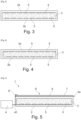
- the actuators 5 can be arranged within the chamber 2 on several of its walls, and according to various configurations. They can for example be located on the two opposite main walls 2a and 2b of the chamber 2, on either side of the fluid 3 and aligned opposite each other, as illustrated in Figure 3 . Such an arrangement makes it possible to increase the mechanical effect of the actuators 5 on a given volume of fluid 3.
- the actuators are located on either side of the fluid 3 in an offset manner, which makes it possible to increase the spatial resolution of the haptic interface and/or to generate more complex haptic effects, depending on the actuators mobilized.
- This offset can be done so that the actuators supported by the wall 2a are centered relative to the middle of the intervals between the actuators of the opposite wall 2b, as illustrated.
- the pitch between the actuators on the wall 2a is different from that between the actuators of the wall 2b, for example a multiple thereof.
- the offset can also be done differently.
- the interface 1 may include one or more additional devices making it possible to improve the user experience, in particular to make it a multi-sensory experience.
- the interface 1 may further comprise one or more speakers 8 to add a sound effect to the experience.
- the display screen 7 is attached to a mount M which can be worn by the user, for example virtual reality glasses as illustrated in Figure 6
- the images displayed on the screen 7 are visible to the user who can simultaneously come into contact with the touch surface S, the control circuit 4 being configured to allow the actuators 5 to generate a haptic effect linked to the image projected or displayed in the frame.
- the actuators 5 are preferably of the piezoelectric type.
- an actuator When an actuator receives an electrical signal from the control circuit 4, it can contract or lengthen by inverse piezoelectric effect, in particular in the direction parallel to the support on which it is fixed. In this case, the piezoelectric material will induce a mechanical torque on the support and therefore by bimetallic effect generate an oscillatory movement.
- each actuator 5 can define an active membrane 21.
- the latter can be formed by a part of the wall 2b of the chamber 2.
- the vibrational behavior of the actuator 5 and the underlying active membrane 21 depends on the way in which the actuator is integrated into its support. This integration can be done in several configurations, and the corresponding vibrational behavior can be simulated using finite element calculation software, such as for example COMSOL software, or any other suitable software. Several example configurations are described below, as well as the vibrational behavior of the associated membrane.
- the actuator 5 is fixed on a support wall 2b which defines an outer surface of the interface 1.
- the vibration of the actuator 5 causes a relatively significant displacement of the membrane 21 in a central zone 210 located under the actuator.
- a zone 211 surrounding the central zone 210 does not show any particular displacement.
- parasitic displacements of the wall 2b are visible beyond the zone 211, in distant zones 212. These parasitic displacements are not desirable because they cause a relatively localized stress on the non-Newtonian fluid, and therefore affect the spatial resolution of the haptic effect.
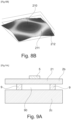
- stiffening ring 9 under the wall 2b delimiting the outline of the active membrane 21, as illustrated in the Figure 8A , allows to limit the amplitude of parasitic movements in the 212 zones, even if they still remain visible on the Figure 8B
- the stiffening ring is made of copper, aluminum, hard plastic, or any other suitable material.
- an outer wall 2c is added, also called a counter-wall, the stiffening ring 9 being integral with the walls 2b and 2c and acting as a spacer between them.
- the membrane 21 is kept at a distance from the wall 2c thanks to the stiffening ring 9, and an air gap 90 may be present between the walls 2b and 2c.
- the movement of the wall 2b under the action of the vibration of the actuator 5 is restricted to the central zone 210 where the actuator is located, and the parasitic movements of the wall 2b are practically absent, as illustrated in Figure 9B .
- a PEN wall 2b with a thickness of the order of 250 ⁇ m and a lead zirconate titanoate (PZT) piezoelectric actuator with a thickness of the order of 30 ⁇ m and a radius of approximately 2500 ⁇ m it is possible to obtain a deformation of the membrane 21 of the order of 5 ⁇ m when the actuator 5 is subjected to an alternating voltage of 50V at a frequency of 1.82 kHz. At this frequency, the non-Newtonian fluid 3 is stressed locally sufficiently to harden and generate, for example, a perception of “pseudo-relief” on the tactile surface S of the interface 1.
- PZT lead zirconate titanoate
- the parasitic displacements of the wall underlying the actuators can be reduced other than by adding a stiffening element 9 and a counter-wall 2c; this can be achieved in particular by actuating neighboring actuators with a phase shift dependent on the distance between the actuators, in particular in phase opposition.
- the thickness of wall 2c is for example 500 ⁇ m. A greater thickness makes it possible to substantially limit the parasitic movements of wall 2b mentioned above, but can in turn reduce the overall flexibility of interface 1.
- the thickness of the wall 2c can be chosen when producing the interface 1 according to the application considered and the desired haptic effect.
- the relative thickness of wall 2c compared to wall 2b is a factor of 10
- the actuator 5 may be of different shapes, for example circular, as illustrated in Figure 11 .
- the actuator 5 comprises a lower electrode 51 connected to the control circuit 4 by a conductive track 41, for example metallic, an active layer 52 for example made of piezoelectric or ferroelectric material, and an upper electrode 53 connected to the control circuit 4 by a conductive track 43, for example metallic.
- the electrodes 51 and 53 are preferably insulated from each other by a passivation layer (not shown).
- the actuator 5 may be supported by an active membrane 21.
- an actuator 5 When an actuator 5 receives a signal from the control circuit 4, a potential difference is applied between the electrodes 51 and 53.
- the signal received by the actuator 5 is for example a complex alternating signal.
- the applied potential difference causes a deformation of the active layer 52, in particular by inverse piezoelectric effect, which causes a displacement of the active membrane 21.
- matrix we mean a single-piece structure carrying several actuators, identical or not.
- the matrix 10 is for example rectangular and of dimensions for example a few centimeters on each side.
- the actuators 5 are in this example identical, each circular in shape and distributed uniformly over the matrix 10, in a staggered pattern.
- the active membrane 21 of each actuator 5 is for example circular in shape.
- the active membrane 21 is of non-circular shape, for example polygonal, in particular square, rectangle, or any other suitable shape, 2D or 3D, the membrane being able to be of convex or concave shape.
- the diameter a of the actuator 5 (that is to say generally its largest dimension) is for example 2500 ⁇ m and of the order of 50% of the diameter d of the active membrane 21, this ratio being advantageous for good deformation of the membrane, as described in the article by Casset, F., et al. "Piezoelectric membrane actuator design.” (12th Intl. Conf. on Thermal, Mechanical & Multi-Physics Simulation and Experiments (Eurosime) 2011 ).
- the active membranes 21 are for example separated from each other by a distance equal to the diameter of membrane 21, this separation distance being advantageous for allowing good spatial resolution of the generated haptic effect.
- the separation distance between the membranes and/or the number of membranes on the matrix 10 are different. It is also possible to have a single isolated membrane.
- the diameter of the membrane 21 is for example of the order of 10 ⁇ m to 100,000 ⁇ m.
- the actuators 5 comprise for example an active layer of lead zirconate titanoate (PZT), and their thickness is for example 30 ⁇ m.
- PZT lead zirconate titanoate
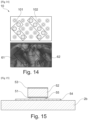
- a group of actuators 100 arranged on the matrix 10 is actuated by the control circuit 4 in order to generate a tactile perception 60 of a “button effect”, that is to say giving the user the impression of pressing a keyboard key.
- actuators 101 and 102 are actuated simultaneously or alternately in order to generate tactile perceptions 61 and 62 of a pseudo-relief effect, that is to say giving the impression to the user who moves his finger in contact with the interface of touching reliefs, for example the crest of a mountain on a map displayed on a screen.
- the actuators 5 of the same group can be modulated according to an actuation amplitude which is identical for all the actuators of the group, or specific to each actuator, depending on the desired effect.
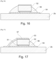
- a piezoelectric actuator 5 can be made following the steps illustrated in figures 15 to 18 .
- a first layer 54 of an electrically conductive material for example silver is deposited, for example by screen printing, on the upper face of a flexible support 2b in order to form the electrical supply track of the actuator 5, possibly in the form of a pad.
- the flexible support 2b is for example a sheet of a polymer of the PEN, PC, PMMA, polyamide, SiNR type or any other suitable material.
- the support 2b may also comprise several layers of several polymers. Its thickness is for example 80 ⁇ m.
- the layer 54 is for example 0.5 ⁇ m thick.
- a piezoelectric ceramic comprising a lower electrode 51, a piezoelectric layer 52 and an upper electrode 53 is then deposited on the layer 54.
- the piezoelectric ceramic is for example a commercial piezoelectric ceramic made of lead zirconate titanoate (PZT). The latter can in particular be thinned and adjusted to a desired thickness.
- a portion of the piezoelectric ceramic is then covered with an electrically insulating layer 56, for example made of a polymer cord, as illustrated in figure 16
- the insulating layer 56 makes it possible to deposit by inkjet printing or other suitable method, a conductive track 57 connected to the upper electrode 53 while avoiding short circuits, in particular with the electrode 51, as illustrated in Figure 17 .
- Track 57 may be in the form of a pad, if necessary.
- Layer 57 is for example 0.5 ⁇ m thick.
- the haptic interface is in standby, in the absence of a user in contact with the touch surface S, and the non-Newtonian fluid has uniform rheological properties under the entire touch surface S.
- the interface 1 according to the invention can be integrated into an item of clothing, for example a glove or a vest, as illustrated in figure 22 .
- the interface 1 may include a touch surface, and/or a detection system 6, on several of its walls, or even on all of its outer faces.
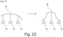
- the chamber 2 may have a shape other than that described above; for example, it is spherical or cylindrical in shape, or may change shape depending on the desired haptic effect, the interface 1 being able to be a reconfigurable tangible object, as illustrated in figure 23 .
- the interface can be mechanically coupled to one or more actuators 11 which allow it to be deformed to give it a predefined shape, corresponding to that of the object that we are seeking to simulate tactilely.
- the stiffening ring 9 is not necessarily circular in shape; it can be of any suitable shape chosen according, for example, to the position of the vibration nodes and antinodes of the wall carrying the actuator.
- the actuators may be produced otherwise than by the manufacturing method described above.
- the active layer 52 is produced by transferring thin films of piezoelectric or ferroelectric materials, in particular lead zirconate titanoate (PZT), aluminum nitride (AIN) or lithium niobate (LNO), or even in multilayers of electroactive polymers, such as polyvinylidene fluoride (PVDF).
- PZT lead zirconate titanoate
- AIN aluminum nitride
- LNO lithium niobate
- electroactive polymers such as polyvinylidene fluoride (PVDF).
Landscapes
- Engineering & Computer Science (AREA)
- General Engineering & Computer Science (AREA)
- Theoretical Computer Science (AREA)
- Human Computer Interaction (AREA)
- Physics & Mathematics (AREA)
- General Physics & Mathematics (AREA)
- User Interface Of Digital Computer (AREA)
Claims (15)
- Flexible haptische Schnittstelle (1), umfassend:- eine Kammer (2), die ein nichtnewtonsches Fluid (3) enthält und mindestens teilweise durch eine flexible Wand (2a) begrenzt wird, deren Außenseite eine taktile Oberfläche (S) definiert, die geeignet ist, von einem Benutzer kontaktiert zu werden,- eine Mehrzahl von Aktoren (5), die von einem flexiblen Träger (2b) getragen werden und so angeordnet sind, dass sie eine lokale mechanische Anregung auf das Fluid (3) übertragen, und- eine Steuerschaltung (4), die mit den Aktoren (5) verbunden ist und dazu ausgestaltet ist, die an die Aktoren gesendeten Signale zu modulieren, um mechanisch eine Änderung der Rheologie des Fluids zu bewirken und eine von dem Benutzer auf der taktilen Oberfläche (S) wahrnehmbare haptische Empfindung zu erzeugen.
- Schnittstelle nach Anspruch 1, wobei die Kammer (2) eine abgeflachte Grundform hat.
- Schnittstelle nach einem der Ansprüche 1 oder 2, wobei die Kammer (2) eine im Wesentlichen konstante Dicke hat.
- Schnittstelle nach einem der vorhergehenden Ansprüche, wobei die Kammer zwischen mindestens zwei entgegengesetzten flexiblen Wänden (2a; 2b) gebildet wird, von denen mindestens eine die taktile Oberfläche (S) definiert, insbesondere Wänden, die biegsame Folien (20) umfassen oder dadurch definiert werden.
- Schnittstelle nach einem der vorhergehenden Ansprüche, wobei die Wand oder Wände (2a, 2b), die die taktile Oberfläche (S) definieren und den Aktoren (5) als Träger dienen, eine Gesamtbiegung der Kammer (2) um mindestens eine Achse, besser in alle Richtungen, ermöglichen.
- Schnittstelle nach einem der vorhergehenden Ansprüche, wobei die Aktoren (5) in Kontakt mit dem Fluid (3) sind.
- Schnittstelle nach einem der vorhergehenden Ansprüche, wobei die Aktoren (5) in mindestens eine Richtung, besser in zwei Richtungen, mit einem regelmäßigen Abstand verteilt sind.
- Schnittstelle nach einem der vorhergehenden Ansprüche, wobei jeder Aktor (5) von einer aktiven Membran (21) getragen wird, die geeignet ist, unter der Einwirkung des Aktors zu vibrieren, wobei die Vibration der Membran das Fluid (3) in dem an den Aktor angrenzenden Bereich mechanisch beansprucht, wobei die Membran (21) bevorzugt durch mindestens einen Teil einer Wand (2b) definiert wird, die den Aktoren (5) als Träger dient, wobei die Wand eine Außenoberfläche der Schnittstelle (1) definiert oder wobei die Wand (2b) von einer Gegenwand (2c) bedeckt wird, wobei die Gegenwand bevorzugt eine Außenoberfläche der Schnittstelle (1) definiert.
- Schnittstelle nach Anspruch 8, umfassend Aussteifungsringe (9) um die Membranen (21) der Aktoren (5), die bevorzugt auf der Seite der Trägerwand (2b) gelegen sind, die entgegengesetzt zu der die Aktoren (5) tragenden ist.
- Schnittstelle nach einem der Ansprüche 1 bis 9, umfassend ein Detektionssystem (6) zum Detektieren eines Kontakts des Benutzers auf der taktilen Oberfläche (S), insbesondere ein kapazitives oder optisches Detektionssystem, wobei die Steuerschaltung (4) dazu ausgebildet ist, die Aktoren (5) in Abhängigkeit von der so detektierten Position zu steuern, und/oder ein System (7), das es ermöglicht, der haptischen Schnittstelle mindestens teilweise ein Bild zu überlagern, insbesondere einen durch die taktile Oberfläche bedeckten Bildschirm, und/oder mindestens einen Aktuator (11), der es ermöglicht, die Schnittstelle selektiv gemäß mindestens zwei verschiedenen Formen zu formen.
- Verfahren zum Erzeugen mindestens einer taktilen Wahrnehmung, die von einem Benutzer beim Kontakt mit einer wie in einem der Ansprüche 1 bis 10 definierten Schnittstelle verspürt werden kann, umfassend die folgenden Schritte:- Detektieren der Position des Kontakts des Benutzers auf der flexiblen taktilen Oberfläche mithilfe eines Detektionssystems,- Modulieren, mithilfe einer Steuerschaltung (4), der an die Aktoren (5) gesendeten Signale, um die Steifigkeit des Fluids in bestimmten Bereichen der Kammer lokal variieren zu lassen und einen von dem Benutzer taktil wahrnehmbaren Effekt zu erzeugen.
- Verfahren nach dem vorhergehenden Anspruch, wobei der Kontakt des Benutzers auf der taktilen Oberfläche mithilfe mindestens eines Teils der Aktoren, insbesondere durch piezoelektrischen Effekt, detektiert wird.
- Verfahren nach einem der Ansprüche 11 und 12, wobei die Steifigkeitsänderung eine taktile Wahrnehmung erzeugt, die dem Benutzer den Eindruck vermittelt, eine ein Relief aufweisende Oberfläche zu berühren.
- Verfahren zur Herstellung einer wie in einem der Ansprüche 1 bis 10 definierten Schnittstelle, umfassend die Herstellung eines Aktors, der Mehrzahl von Aktoren, vom piezoelektrischen keramischen Typ durch die folgenden Schritte:- Aufbringen mindestens einer ersten Schicht (54) eines leitenden Materials auf die Oberseite eines flexiblen Trägers (2b), bevorzugt einer flexiblen Polymerfolie,- Fixieren einer piezoelektrischen Keramik (51) auf der so gebildeten leitenden Schicht,- Aufbringen, insbesondere durch Tintenstrahldruck, einer Schicht aus einem leitenden Material (57) auf die piezoelektrische Keramik,- Aufbringen einer Schicht aus einem elektrischen Isolierstoff (58), der bevorzugt durch Drucken aufgebracht wird, auf die zuvor aufgebrachten Schichten.
- Verfahren zur Herstellung einer wie in einem der Ansprüche 1 bis 10 definierten Schnittstelle, umfassend die folgenden Schritte:
Verbinden von zweien der flexiblen Wände (2a, 2b), insbesondere durch Schweißen oder Kleben, so dass die Kammer (2) gebildet wird, wobei mindestens eine der Wände die Aktoren (5) auf einer ihrer Seiten aufweist.
Applications Claiming Priority (1)
| Application Number | Priority Date | Filing Date | Title |
|---|---|---|---|
| FR2102601A FR3120960B1 (fr) | 2021-03-16 | 2021-03-16 | Interface haptique flexible |
Publications (2)
| Publication Number | Publication Date |
|---|---|
| EP4060461A1 EP4060461A1 (de) | 2022-09-21 |
| EP4060461B1 true EP4060461B1 (de) | 2025-06-25 |
Family
ID=75954028
Family Applications (1)
| Application Number | Title | Priority Date | Filing Date |
|---|---|---|---|
| EP22162057.8A Active EP4060461B1 (de) | 2021-03-16 | 2022-03-15 | Flexible haptische schnittstelle |
Country Status (3)
| Country | Link |
|---|---|
| US (1) | US11592904B2 (de) |
| EP (1) | EP4060461B1 (de) |
| FR (1) | FR3120960B1 (de) |
Families Citing this family (2)
| Publication number | Priority date | Publication date | Assignee | Title |
|---|---|---|---|---|
| FR3128546B1 (fr) * | 2021-10-25 | 2024-01-12 | Commissariat A L’Energie Atomique Et Aux Energies Alternatives | Interface haptique à charnières souples |
| KR102785188B1 (ko) * | 2023-01-11 | 2025-03-20 | 성균관대학교산학협력단 | 진동 저항형 건식 피부 접착 패치 |
Family Cites Families (7)
| Publication number | Priority date | Publication date | Assignee | Title |
|---|---|---|---|---|
| US8243038B2 (en) * | 2009-07-03 | 2012-08-14 | Tactus Technologies | Method for adjusting the user interface of a device |
| US9063627B2 (en) * | 2008-01-04 | 2015-06-23 | Tactus Technology, Inc. | User interface and methods |
| US9829977B2 (en) * | 2008-04-02 | 2017-11-28 | Immersion Corporation | Method and apparatus for providing multi-point haptic feedback texture systems |
| WO2010078597A1 (en) | 2009-01-05 | 2010-07-08 | Tactus Technology, Inc. | User interface system |
| KR101661728B1 (ko) * | 2010-05-11 | 2016-10-04 | 삼성전자주식회사 | 사용자 입력 장치 및 이를 구비한 전자 기기 |
| JP6736481B2 (ja) * | 2014-03-14 | 2020-08-05 | メルク パテント ゲゼルシャフト ミット ベシュレンクテル ハフツングMerck Patent Gesellschaft mit beschraenkter Haftung | 電気粘性流体および触覚デバイス |
| US11413820B2 (en) * | 2019-03-18 | 2022-08-16 | X Development Llc | Sensing and feedback for the formation of complex three-dimensional acoustic fields |
-
2021
- 2021-03-16 FR FR2102601A patent/FR3120960B1/fr active Active
-
2022
- 2022-03-15 EP EP22162057.8A patent/EP4060461B1/de active Active
- 2022-03-15 US US17/694,874 patent/US11592904B2/en active Active
Also Published As
| Publication number | Publication date |
|---|---|
| EP4060461A1 (de) | 2022-09-21 |
| US11592904B2 (en) | 2023-02-28 |
| US20220300076A1 (en) | 2022-09-22 |
| FR3120960B1 (fr) | 2024-01-12 |
| FR3120960A1 (fr) | 2022-09-23 |
Similar Documents
| Publication | Publication Date | Title |
|---|---|---|
| US9820055B2 (en) | Transducer system | |
| EP4006698B1 (de) | Haptische schnittstelle | |
| EP4060461A1 (de) | Flexible haptische schnittstelle | |
| EP4232884B1 (de) | Dreidimensionale berührungsschnittstelle mit haptischer rückmeldung | |
| EP4170468A1 (de) | Haptische schnittstelle mit flexiblem scharnier | |
| FR2991791A1 (fr) | Interface de stimulation tactile par retournement temporel | |
| EP3729241B1 (de) | Flächige vorrichtung mit verbesserter lokalisierter verformung | |
| WO2018178582A1 (fr) | Interface offrant une modulation de friction localisée par lubrification acoustique | |
| EP4047453B1 (de) | Flexible haptische schnittstelle | |
| EP3516442B1 (de) | Vorrichtung mit einer hängenden membran mit erhöhter verdrängungsamplitude | |
| EP3123212A1 (de) | Optische vorrichtung mit einer deformierbaren membran | |
| WO2019122762A1 (fr) | Dispositif surfacique offrant une deformation localisee amelioree | |
| WO2022090090A1 (fr) | Dispositif tactile à retour haptique avec textures spatialisées | |
| EP3631608B1 (de) | Verfahren zur steuerung einer mobilen vorrichtung | |
| FR3150018A1 (fr) | Interface haptique flexible | |
| WO2023111444A1 (fr) | Dispositif de modulation de friction localisée par vibrations dans une interface vibrante à surface de contact | |
| EP4542346A1 (de) | Haptische und akustische schnittstelle | |
| FR3063156A1 (fr) | Interface d'entree notamment utilisable pour l'affichage |
Legal Events
| Date | Code | Title | Description |
|---|---|---|---|
| PUAI | Public reference made under article 153(3) epc to a published international application that has entered the european phase |
Free format text: ORIGINAL CODE: 0009012 |
|
| STAA | Information on the status of an ep patent application or granted ep patent |
Free format text: STATUS: REQUEST FOR EXAMINATION WAS MADE |
|
| 17P | Request for examination filed |
Effective date: 20220315 |
|
| AK | Designated contracting states |
Kind code of ref document: A1 Designated state(s): AL AT BE BG CH CY CZ DE DK EE ES FI FR GB GR HR HU IE IS IT LI LT LU LV MC MK MT NL NO PL PT RO RS SE SI SK SM TR |
|
| RAP3 | Party data changed (applicant data changed or rights of an application transferred) |
Owner name: COMMISSARIAT A L'ENERGIE ATOMIQUE ET AUX ENERGIESALTERNATIVES |
|
| GRAP | Despatch of communication of intention to grant a patent |
Free format text: ORIGINAL CODE: EPIDOSNIGR1 |
|
| STAA | Information on the status of an ep patent application or granted ep patent |
Free format text: STATUS: GRANT OF PATENT IS INTENDED |
|
| INTG | Intention to grant announced |
Effective date: 20250305 |
|
| GRAS | Grant fee paid |
Free format text: ORIGINAL CODE: EPIDOSNIGR3 |
|
| GRAA | (expected) grant |
Free format text: ORIGINAL CODE: 0009210 |
|
| STAA | Information on the status of an ep patent application or granted ep patent |
Free format text: STATUS: THE PATENT HAS BEEN GRANTED |
|
| AK | Designated contracting states |
Kind code of ref document: B1 Designated state(s): AL AT BE BG CH CY CZ DE DK EE ES FI FR GB GR HR HU IE IS IT LI LT LU LV MC MK MT NL NO PL PT RO RS SE SI SK SM TR |
|
| REG | Reference to a national code |
Ref country code: GB Ref legal event code: FG4D Free format text: NOT ENGLISH |
|
| REG | Reference to a national code |
Ref country code: CH Ref legal event code: EP |
|
| REG | Reference to a national code |
Ref country code: CH Ref legal event code: EP |
|
| REG | Reference to a national code |
Ref country code: IE Ref legal event code: FG4D Free format text: LANGUAGE OF EP DOCUMENT: FRENCH |
|
| REG | Reference to a national code |
Ref country code: DE Ref legal event code: R096 Ref document number: 602022016289 Country of ref document: DE |
|
| PG25 | Lapsed in a contracting state [announced via postgrant information from national office to epo] |
Ref country code: FI Free format text: LAPSE BECAUSE OF FAILURE TO SUBMIT A TRANSLATION OF THE DESCRIPTION OR TO PAY THE FEE WITHIN THE PRESCRIBED TIME-LIMIT Effective date: 20250625 |
|
| REG | Reference to a national code |
Ref country code: LT Ref legal event code: MG9D |
|
| PG25 | Lapsed in a contracting state [announced via postgrant information from national office to epo] |
Ref country code: NO Free format text: LAPSE BECAUSE OF FAILURE TO SUBMIT A TRANSLATION OF THE DESCRIPTION OR TO PAY THE FEE WITHIN THE PRESCRIBED TIME-LIMIT Effective date: 20250925 Ref country code: GR Free format text: LAPSE BECAUSE OF FAILURE TO SUBMIT A TRANSLATION OF THE DESCRIPTION OR TO PAY THE FEE WITHIN THE PRESCRIBED TIME-LIMIT Effective date: 20250926 |
|
| PG25 | Lapsed in a contracting state [announced via postgrant information from national office to epo] |
Ref country code: BG Free format text: LAPSE BECAUSE OF FAILURE TO SUBMIT A TRANSLATION OF THE DESCRIPTION OR TO PAY THE FEE WITHIN THE PRESCRIBED TIME-LIMIT Effective date: 20250625 |
|
| PG25 | Lapsed in a contracting state [announced via postgrant information from national office to epo] |
Ref country code: HR Free format text: LAPSE BECAUSE OF FAILURE TO SUBMIT A TRANSLATION OF THE DESCRIPTION OR TO PAY THE FEE WITHIN THE PRESCRIBED TIME-LIMIT Effective date: 20250625 |
|
| PG25 | Lapsed in a contracting state [announced via postgrant information from national office to epo] |
Ref country code: RS Free format text: LAPSE BECAUSE OF FAILURE TO SUBMIT A TRANSLATION OF THE DESCRIPTION OR TO PAY THE FEE WITHIN THE PRESCRIBED TIME-LIMIT Effective date: 20250925 |
|
| PG25 | Lapsed in a contracting state [announced via postgrant information from national office to epo] |
Ref country code: LV Free format text: LAPSE BECAUSE OF FAILURE TO SUBMIT A TRANSLATION OF THE DESCRIPTION OR TO PAY THE FEE WITHIN THE PRESCRIBED TIME-LIMIT Effective date: 20250625 |
|
| REG | Reference to a national code |
Ref country code: NL Ref legal event code: MP Effective date: 20250625 |
|
| PG25 | Lapsed in a contracting state [announced via postgrant information from national office to epo] |
Ref country code: NL Free format text: LAPSE BECAUSE OF FAILURE TO SUBMIT A TRANSLATION OF THE DESCRIPTION OR TO PAY THE FEE WITHIN THE PRESCRIBED TIME-LIMIT Effective date: 20250625 |
|
| PG25 | Lapsed in a contracting state [announced via postgrant information from national office to epo] |
Ref country code: PT Free format text: LAPSE BECAUSE OF FAILURE TO SUBMIT A TRANSLATION OF THE DESCRIPTION OR TO PAY THE FEE WITHIN THE PRESCRIBED TIME-LIMIT Effective date: 20251027 |
|
| REG | Reference to a national code |
Ref country code: AT Ref legal event code: MK05 Ref document number: 1807135 Country of ref document: AT Kind code of ref document: T Effective date: 20250625 |
|
| PG25 | Lapsed in a contracting state [announced via postgrant information from national office to epo] |
Ref country code: IS Free format text: LAPSE BECAUSE OF FAILURE TO SUBMIT A TRANSLATION OF THE DESCRIPTION OR TO PAY THE FEE WITHIN THE PRESCRIBED TIME-LIMIT Effective date: 20251025 |
|
| PG25 | Lapsed in a contracting state [announced via postgrant information from national office to epo] |
Ref country code: AT Free format text: LAPSE BECAUSE OF FAILURE TO SUBMIT A TRANSLATION OF THE DESCRIPTION OR TO PAY THE FEE WITHIN THE PRESCRIBED TIME-LIMIT Effective date: 20250625 Ref country code: SM Free format text: LAPSE BECAUSE OF FAILURE TO SUBMIT A TRANSLATION OF THE DESCRIPTION OR TO PAY THE FEE WITHIN THE PRESCRIBED TIME-LIMIT Effective date: 20250625 |
|
| PG25 | Lapsed in a contracting state [announced via postgrant information from national office to epo] |
Ref country code: CZ Free format text: LAPSE BECAUSE OF FAILURE TO SUBMIT A TRANSLATION OF THE DESCRIPTION OR TO PAY THE FEE WITHIN THE PRESCRIBED TIME-LIMIT Effective date: 20250625 |
|
| PG25 | Lapsed in a contracting state [announced via postgrant information from national office to epo] |
Ref country code: PL Free format text: LAPSE BECAUSE OF FAILURE TO SUBMIT A TRANSLATION OF THE DESCRIPTION OR TO PAY THE FEE WITHIN THE PRESCRIBED TIME-LIMIT Effective date: 20250625 |
|
| PG25 | Lapsed in a contracting state [announced via postgrant information from national office to epo] |
Ref country code: EE Free format text: LAPSE BECAUSE OF FAILURE TO SUBMIT A TRANSLATION OF THE DESCRIPTION OR TO PAY THE FEE WITHIN THE PRESCRIBED TIME-LIMIT Effective date: 20250625 |
|
| PG25 | Lapsed in a contracting state [announced via postgrant information from national office to epo] |
Ref country code: SK Free format text: LAPSE BECAUSE OF FAILURE TO SUBMIT A TRANSLATION OF THE DESCRIPTION OR TO PAY THE FEE WITHIN THE PRESCRIBED TIME-LIMIT Effective date: 20250625 |
|
| PG25 | Lapsed in a contracting state [announced via postgrant information from national office to epo] |
Ref country code: ES Free format text: LAPSE BECAUSE OF FAILURE TO SUBMIT A TRANSLATION OF THE DESCRIPTION OR TO PAY THE FEE WITHIN THE PRESCRIBED TIME-LIMIT Effective date: 20250625 |
|
| PGFP | Annual fee paid to national office [announced via postgrant information from national office to epo] |
Ref country code: GB Payment date: 20260324 Year of fee payment: 5 |
|
| PG25 | Lapsed in a contracting state [announced via postgrant information from national office to epo] |
Ref country code: DK Free format text: LAPSE BECAUSE OF FAILURE TO SUBMIT A TRANSLATION OF THE DESCRIPTION OR TO PAY THE FEE WITHIN THE PRESCRIBED TIME-LIMIT Effective date: 20250625 |
|
| PGFP | Annual fee paid to national office [announced via postgrant information from national office to epo] |
Ref country code: DE Payment date: 20260320 Year of fee payment: 5 |
|
| PG25 | Lapsed in a contracting state [announced via postgrant information from national office to epo] |
Ref country code: IT Free format text: LAPSE BECAUSE OF FAILURE TO SUBMIT A TRANSLATION OF THE DESCRIPTION OR TO PAY THE FEE WITHIN THE PRESCRIBED TIME-LIMIT Effective date: 20250625 |
|
| PGFP | Annual fee paid to national office [announced via postgrant information from national office to epo] |
Ref country code: FR Payment date: 20260324 Year of fee payment: 5 |
|
| PLBE | No opposition filed within time limit |
Free format text: ORIGINAL CODE: 0009261 |
|
| STAA | Information on the status of an ep patent application or granted ep patent |
Free format text: STATUS: NO OPPOSITION FILED WITHIN TIME LIMIT |
|
| REG | Reference to a national code |
Ref country code: CH Ref legal event code: L10 Free format text: ST27 STATUS EVENT CODE: U-0-0-L10-L00 (AS PROVIDED BY THE NATIONAL OFFICE) Effective date: 20260507 |