EP4015902A1 - Luminaire avec des bandes pour le montage et le démontage - Google Patents
Luminaire avec des bandes pour le montage et le démontage Download PDFInfo
- Publication number
- EP4015902A1 EP4015902A1 EP21214573.4A EP21214573A EP4015902A1 EP 4015902 A1 EP4015902 A1 EP 4015902A1 EP 21214573 A EP21214573 A EP 21214573A EP 4015902 A1 EP4015902 A1 EP 4015902A1
- Authority
- EP
- European Patent Office
- Prior art keywords
- light fitting
- panel
- light
- cable tie
- flange
- Prior art date
- Legal status (The legal status is an assumption and is not a legal conclusion. Google has not performed a legal analysis and makes no representation as to the accuracy of the status listed.)
- Pending
Links
- 238000009434 installation Methods 0.000 claims abstract description 73
- 230000007246 mechanism Effects 0.000 claims abstract description 59
- 238000007789 sealing Methods 0.000 claims description 40
- 239000000463 material Substances 0.000 claims description 17
- 230000001066 destructive effect Effects 0.000 claims description 14
- 238000000034 method Methods 0.000 claims description 10
- 238000010276 construction Methods 0.000 claims description 8
- 238000005253 cladding Methods 0.000 claims description 2
- 230000008901 benefit Effects 0.000 description 30
- 239000007788 liquid Substances 0.000 description 12
- XLYOFNOQVPJJNP-UHFFFAOYSA-N water Substances O XLYOFNOQVPJJNP-UHFFFAOYSA-N 0.000 description 8
- 238000005516 engineering process Methods 0.000 description 5
- 230000002441 reversible effect Effects 0.000 description 5
- 229920002943 EPDM rubber Polymers 0.000 description 4
- 229920001084 poly(chloroprene) Polymers 0.000 description 4
- 230000003287 optical effect Effects 0.000 description 3
- 238000010586 diagram Methods 0.000 description 2
- 230000000694 effects Effects 0.000 description 2
- 229920001971 elastomer Polymers 0.000 description 2
- 230000005611 electricity Effects 0.000 description 2
- 230000014509 gene expression Effects 0.000 description 2
- 230000005484 gravity Effects 0.000 description 2
- 238000003780 insertion Methods 0.000 description 2
- 230000037431 insertion Effects 0.000 description 2
- 238000002844 melting Methods 0.000 description 2
- 230000008018 melting Effects 0.000 description 2
- 229910052751 metal Inorganic materials 0.000 description 2
- 239000005060 rubber Substances 0.000 description 2
- 244000043261 Hevea brasiliensis Species 0.000 description 1
- 239000008186 active pharmaceutical agent Substances 0.000 description 1
- 238000007792 addition Methods 0.000 description 1
- 230000008859 change Effects 0.000 description 1
- 238000004140 cleaning Methods 0.000 description 1
- 238000004891 communication Methods 0.000 description 1
- 238000012937 correction Methods 0.000 description 1
- 238000005520 cutting process Methods 0.000 description 1
- 238000009826 distribution Methods 0.000 description 1
- 238000010616 electrical installation Methods 0.000 description 1
- 238000010438 heat treatment Methods 0.000 description 1
- 239000002184 metal Substances 0.000 description 1
- 229920003052 natural elastomer Polymers 0.000 description 1
- 229920001194 natural rubber Polymers 0.000 description 1
- 238000010422 painting Methods 0.000 description 1
- 229920000642 polymer Polymers 0.000 description 1
- 239000002861 polymer material Substances 0.000 description 1
- 229920001296 polysiloxane Polymers 0.000 description 1
- 230000000717 retained effect Effects 0.000 description 1
- 238000010008 shearing Methods 0.000 description 1
- 238000004381 surface treatment Methods 0.000 description 1
- 229920003051 synthetic elastomer Polymers 0.000 description 1
- 239000005061 synthetic rubber Substances 0.000 description 1
- 235000012773 waffles Nutrition 0.000 description 1
Images





Classifications
-
- F—MECHANICAL ENGINEERING; LIGHTING; HEATING; WEAPONS; BLASTING
- F21—LIGHTING
- F21V—FUNCTIONAL FEATURES OR DETAILS OF LIGHTING DEVICES OR SYSTEMS THEREOF; STRUCTURAL COMBINATIONS OF LIGHTING DEVICES WITH OTHER ARTICLES, NOT OTHERWISE PROVIDED FOR
- F21V21/00—Supporting, suspending, or attaching arrangements for lighting devices; Hand grips
- F21V21/02—Wall, ceiling, or floor bases; Fixing pendants or arms to the bases
- F21V21/04—Recessed bases
- F21V21/041—Mounting arrangements specially adapted for false ceiling panels or partition walls made of plates
- F21V21/042—Mounting arrangements specially adapted for false ceiling panels or partition walls made of plates using clamping means, e.g. for clamping with panel or wall
-
- F—MECHANICAL ENGINEERING; LIGHTING; HEATING; WEAPONS; BLASTING
- F21—LIGHTING
- F21V—FUNCTIONAL FEATURES OR DETAILS OF LIGHTING DEVICES OR SYSTEMS THEREOF; STRUCTURAL COMBINATIONS OF LIGHTING DEVICES WITH OTHER ARTICLES, NOT OTHERWISE PROVIDED FOR
- F21V17/00—Fastening of component parts of lighting devices, e.g. shades, globes, refractors, reflectors, filters, screens, grids or protective cages
- F21V17/10—Fastening of component parts of lighting devices, e.g. shades, globes, refractors, reflectors, filters, screens, grids or protective cages characterised by specific fastening means or way of fastening
-
- F—MECHANICAL ENGINEERING; LIGHTING; HEATING; WEAPONS; BLASTING
- F21—LIGHTING
- F21S—NON-PORTABLE LIGHTING DEVICES; SYSTEMS THEREOF; VEHICLE LIGHTING DEVICES SPECIALLY ADAPTED FOR VEHICLE EXTERIORS
- F21S8/00—Lighting devices intended for fixed installation
- F21S8/02—Lighting devices intended for fixed installation of recess-mounted type, e.g. downlighters
- F21S8/026—Lighting devices intended for fixed installation of recess-mounted type, e.g. downlighters intended to be recessed in a ceiling or like overhead structure, e.g. suspended ceiling
-
- F—MECHANICAL ENGINEERING; LIGHTING; HEATING; WEAPONS; BLASTING
- F21—LIGHTING
- F21V—FUNCTIONAL FEATURES OR DETAILS OF LIGHTING DEVICES OR SYSTEMS THEREOF; STRUCTURAL COMBINATIONS OF LIGHTING DEVICES WITH OTHER ARTICLES, NOT OTHERWISE PROVIDED FOR
- F21V17/00—Fastening of component parts of lighting devices, e.g. shades, globes, refractors, reflectors, filters, screens, grids or protective cages
-
- F—MECHANICAL ENGINEERING; LIGHTING; HEATING; WEAPONS; BLASTING
- F21—LIGHTING
- F21V—FUNCTIONAL FEATURES OR DETAILS OF LIGHTING DEVICES OR SYSTEMS THEREOF; STRUCTURAL COMBINATIONS OF LIGHTING DEVICES WITH OTHER ARTICLES, NOT OTHERWISE PROVIDED FOR
- F21V17/00—Fastening of component parts of lighting devices, e.g. shades, globes, refractors, reflectors, filters, screens, grids or protective cages
- F21V17/02—Fastening of component parts of lighting devices, e.g. shades, globes, refractors, reflectors, filters, screens, grids or protective cages with provision for adjustment
-
- F—MECHANICAL ENGINEERING; LIGHTING; HEATING; WEAPONS; BLASTING
- F21—LIGHTING
- F21V—FUNCTIONAL FEATURES OR DETAILS OF LIGHTING DEVICES OR SYSTEMS THEREOF; STRUCTURAL COMBINATIONS OF LIGHTING DEVICES WITH OTHER ARTICLES, NOT OTHERWISE PROVIDED FOR
- F21V17/00—Fastening of component parts of lighting devices, e.g. shades, globes, refractors, reflectors, filters, screens, grids or protective cages
- F21V17/10—Fastening of component parts of lighting devices, e.g. shades, globes, refractors, reflectors, filters, screens, grids or protective cages characterised by specific fastening means or way of fastening
- F21V17/16—Fastening of component parts of lighting devices, e.g. shades, globes, refractors, reflectors, filters, screens, grids or protective cages characterised by specific fastening means or way of fastening by deformation of parts; Snap action mounting
Definitions
- the present invention concerns a light fitting and, more specifically, a light fitting with a cable tie for installation and removal and also concerns a lamp, a construction element and the use of these.
- the purpose of the present invention is to provide a light fitting that can be installed in a (relatively) short time and/or can be removed without a cup needing to be damaged during removal.
- the first aspect of the invention concerns a light fitting for installation in a panel, with the light fitting comprising:
- An advantage of the invention may be that it is possible to install the light fitting in a panel quickly and/or by simple means. For example, it may be possible to position the light fitting with the primary flange arrangement on a first side of the panel and the secondary flange arrangement on the other side of the panel and, by means of the ratchet, reduce the distance between the primary flange arrangement and the secondary flange arrangement until the flanges are flush with the first and second sides of the panel respectively and thereby grip the panel and secure the light fitting in a fixed position in relation to the panel. It may therefore be possible to install the light fitting by only using the ratchet.
- Another possible advantage of the invention could be that it is possible to remove the light fitting quickly and/or by simple means. For example, it could be possible to access a tensioned part of the cable tie from the first side of the panel (i.e., the same side as the side from which the light source can be accessed) and, for example, break the tension by cutting or shearing or melting the cable tie so that the primary and secondary flange arrangements and secondary flange arrangement are no longer secured in a locked condition that grips the panel whereby the light fitting can be dismantled or removed from the panel.
- the tensioned part of the cable tie can be accessed from the first side of the panel because it is then not necessary to gain access to the second side of the panel (which could, for example, be from the ceiling side of a ceiling covering) and/or the fact that it is not necessary to carry out a destructive encroachment on the box. It could therefore be possible to remove the light fitting from the panel, e.g., in order to access the electrical connector positioned outside the box on the other side of the panel without destroying the box, which can thus be re-installed, e.g., using a new cable tie.
- the term "light fitting” is to be understood as meaning a supporting structure for facilitating a fixed structural, and optionally electrical, connection between, on the one hand a structural element and a possible electrical installation and, on the other hand, a light source, e.g., where the light fitting includes a holder (e.g., including a lamp holder) that can be installed in a structural element and to which an electrical connection may be connected and where a light source (e.g., an LED light source or a light bulb, such as a filament bulb or a gas discharge lamp) can be inserted in a relationship, such as a fixed relationship (i.e., without translational degrees of freedom) to the light fitting and structural element.
- a light source e.g., an LED light source or a light bulb, such as a filament bulb or a gas discharge lamp
- the light fitting could optionally have the meaning of the parts that correspond to the lamp without the light source.
- installation in a panel is to be understood as meaning, for example, installation in a cavity (e.g., a tight-fitting cavity in relation to the light fitting) in a panel, such as a panel with a thickness comparable with or less thick than the length of the light fitting (along an optical axis of the light fitting).
- a cavity e.g., a tight-fitting cavity in relation to the light fitting
- a panel such as a panel with a thickness comparable with or less thick than the length of the light fitting (along an optical axis of the light fitting).
- the term "panel” is to be understood as having the meaning it normally has in the field of technology, for example, generally as a thin (such as in a thickness that is less, such as in considerably less, than the length and width), large (such as in length and width, such as in considerably bigger, than the length and width of the light fitting, e.g., in directions at a right angle in an optical axis of the light fitting), and possibly flat, such as a first side of the panel and a second side of the panel each being separately flat and parallel, e.g., at least in the area around the light fitting.
- box is understood to have the meaning of an element, such as a shell, comprising a cavity arranged to enclose a light source, e.g., a box comprising a lamp holder for the insertion of a light source.
- a light source e.g., a box comprising a lamp holder for the insertion of a light source.
- Some embodiments of the box could be monolithic.
- the term, "light source” can mean an electric light source, such as an LED (“light emitting diode”) light source and/or an electric light source with a base or a socket, such as an LED light source with a so-called GU10 base.
- the light source may be partly conical where the surface through which the light can be emitted matches the circular end face of the cone.
- the light source may have an essentially flat surface, such as a circular end face, through which light can be emitted where the flat surface has an extent such as a diameter of, for example 10 mm, 25 mm, 50 mm or 100 mm.
- the light source has a circular symmetrical cut edge (which may be flush with a circular flange).
- the light source is partly cone shaped and light is emitted through the circular end face of the cone, which has a diameter of 10 mm, 25 mm, 50 mm or 100 mm.
- base shall be understood as meaning part of the light source that is arranged to form part of a fixed connection with a lamp holder (e.g., a GU10 base on a GU10 light source that fits a GU10 lamp holder in a light fitting).
- the term, "where the light fitting is arranged in such a way that the light source can be accessed from a first side of the panel after installation” can mean that, following the installation of the light fitting in a panel, e.g., in a cavity in the panel that closes tightly around the light fitting (so that one does not have access the opposite side of the panel via a passage between light fitting and panel) and where the panel is - in principal - big enough (length and breadth) or infinite so that there is no access to the other side of the panel via a passage around the panel), the light source can be accessed and, for example, be replaced from a first side of the panel as well as only from a first side of the panel.
- the light fitting may, for example, be connected electrically to an electricity network via an electrical connector placed on the other side of the box in relation to the light source.
- ratchet is understood to have the meaning of a device consisting of a cable tie with a surface (e.g., with teeth, such as in asymmetrical teeth or barbs) arranged in relation to a detent so that the cable tie can be moved in one direction past the detent (which has a "freewheel” in one direction) but not in the opposite direction or can only be moved in the opposite direction with more force than the force required to retain the light fitting in the panel (e.g., so that, for example, the effect of the gravitational force on the light fitting is less than the force required in order to move the cable tie in the other direction).
- a surface e.g., with teeth, such as in asymmetrical teeth or barbs
- the force used in moving the cable tie in the first direction is just as great or greater than the force that makes it possible to move the cable tie in the other direction.
- One advantage in installation by means of a ratchet could be that there will be a greater span of panel thicknesses that can be installed, such as in as relatively greater (e.g., compared with installation using a screw where, for example, the height/length of the thread imposes a restriction).
- greater force will be required to move the cable tie in a direction other than the first (where the other direction is the direction in which the primary and secondary flange arrangements are moved from each other. This could have the advantage of it being relatively easy to install the light fitting while it is subsequently still fixed securely.
- cable tie is understood as having its usual meaning in the field of technology, a longish item that can function in a ratchet, e.g., by means of teeth or asymmetrical teeth or barbs. This is an assumption and subject to it being possible to have one or more cable ties, and this particularly comprises that there can be several cable ties, such as 2, 3, 4, 6, 8, 12 or more cable ties and further understood to have the meaning that there can be an equivalent number of ratchets.
- the preferred embodiments have 2 or more cable ties.
- the extra cable ties can be distributed with equidistant spacing in terms of angles, e.g., 180° between two cable ties, 120° between the nearest cable ties in the case of three cable ties and generally 360°/n between the nearest cable tie in the case of n cable ties.
- One advantage with this is that it will therefore be easier and/or possible to assess matters more precisely and potentially even quantify the position of each individual cable tie.
- ratchet mechanism is understood to have the meaning of the arrangement that makes it possible to allow the cable tie to move in one direction but not the other or only in the other direction when subjected to the aforementioned force, e.g., the part or area of the device in which cable tie and detent interact.
- the term "arranged so as to prevent a relative movement between the cable tie and a part of the light fitting, such as the remaining part of the light fitting that does not cover the cable tie in at least one direction” is understood to have the meaning of the force required to move the cable tie in the other direction being greater than the force required to retain the light fitting in the panel (e.g., so that the effect of gravity on the light fitting is less than the force required to move the cable tie the other way).
- flange arrangement is understood to have the meaning of a flange arrangement comprising a flange such as a flange that entirely or partially covers the box or one or more primary flange components, such as taps or suchlike that can have the same function as a flange, such as a function where they can be flush with the first or second side of the panel and thereby ensure that the light fitting cannot be moved further in a direction at right angles to the panel.
- flange or “flange component” generally mean a prominent edge or joint, such as a prominent edge on a cylindrical item.
- a distance between the primary flange arrangement and the secondary flange arrangement can be reduced by means of the ratchet, e.g., through the primary flange arrangement being positioned on the box and the secondary flange arrangement being positioned on the cable tie and where the cable tie can be moved in one direction (such as a direction parallel with an optical axis for the light fitting and/or parallel with the panel comparison specimen) by means of the ratchet mechanism so that the primary and secondary flange arrangements move towards each other.
- the installation can be by means of the box's (primary) ratchet arrangement being initially positioned on the first side of the panel and the cable tie's (secondary) ratchet arrangement being positioned on the other side of the panel and them being moved towards each other and at one time being positioned against each side of the panel and pressed securely around the panel.
- the light fitting can be installed in the panel using a ratchet that will lock the relative distance between the primary flange arrangement and the secondary flange arrangement.
- tensioned part of the cable tie is understood to mean the part of the cable tie that is tensioned following installation and that thereby holds the primary and secondary flange arrangement at a limited and/or locked distance and thereby holds the light fitting securely.
- the tensioned part could, for example be a part of the cable tie between a flange arrangement on the cable tie and the ratchet mechanism/detent.
- the term, "where the light fitting is arranged in such a way that a tensioned part of the cable tie is accessible from a first side of the panel after installation” can mean that, following the installation of the light fitting in a panel, e.g., in a cavity in the panel that closes tightly around the light fitting (so that one does not have access to the opposite side of the panel via a passage between light fitting and panel) and where the panel is - in principal -big enough (length and breadth) or infinite so that there is no access to the other side of the panel via a passage around the panel), a tensioned part of the cable tie can be accessed (the tension can be broken (as discussed above)) from a first side of the panel.
- the light fitting could, for example, be electrically connected to an electricity network by means of an electrical connector positioned on the other side of the box in relation to the light source and it may be necessary to access the connector from the first side (while a destructive encroachment may be necessary on the ceiling panel to reach from the other side) and embodiments of the invention offer this opportunity without it being necessary to carry out a destructive encroachment on either the box or ceiling panel because the tensioned part of the cable tie can be accessed from the first side.
- a light fitting where the light fitting also comprises a sealing element.
- a sealing element is understood to mean an element or possibly a collection of sub elements that can be positioned in relation to the light fitting and panel in such a way that it seals an opening between the panel and lighting element, e.g., so that less air and/or moisture can pass between the panel and the lighting element after installation.
- the term "seals an opening between the panel and lighting element” is understood to mean that less air and/or moisture can pass through the opening after installation, but not necessarily that the sealing element is in the actual opening (this may also be positioned on one side or the other).
- a sealing element may, for example, be made up of an element that covers the box in a way that it tightly covers the box.
- the material for the sealing element may be relatively less rigid (i.e., have a lower Young's modulus) than the material from which the box is made.
- One advantage of this may be that this can more easily be fitted tightly to the panel where the lower Young's modulus could make the sealing element adjust to any distortion and irregularities and tightly sealed despite any such distortions and irregularities.
- the sealing element can, for example, be performed entirely or partly from polymer (such as ethylenepropylene-diene-monomer (EPDM), silicone, neoprene and/or polychloroprene, which is a polymer material containing gas bubbles), and/or rubber (such as ethylene-propylene-diene-monomer (EPDM), neoprene and/or polychloroprene, such as a rubber material containing gas bubbles), such as natural rubber or synthetic rubber.
- polymer such as ethylenepropylene-diene-monomer (EPDM), silicone, neoprene and/or polychloroprene, which is a polymer material containing gas bubbles
- rubber such as ethylene-propylene-diene-monomer (EPDM), neoprene and/or polychloroprene, such as a rubber material containing gas bubbles
- the sealing element may have a pattern, such as a honeycomb or waffle pattern and/or a corrugated surface (which may be preferable for increased strength).
- a light fitting is presented where the sealing element is arranged in such a way that part of the sealing element or entire sealing element can be shifted in relation to the box (such as in shifted in a direction parallel with a direction corresponding to the difference when a distance between the primary flange arrangement and the secondary flange arrangement is reduced by means of the ratchet), possibly under the influence of the ratchet (so that the light fitting can be arranged in such a way than when a distance between the primary flange arrangement and the secondary flange arrangement is reduced by means of the ratchet, the sealing element can also be shifted) so that the sealing element can, while being installed in the panel, be pressed against the panel and thereby put into a position where it seals an opening between the panel and the light fitting.
- An advantage with this could be that a better seal can also be achieved in an effective manner during installation.
- a light fitting is presented where the light fitting is arranged in such a way that, during installation in the panel, fixing can take place by means of elements, such as the ratchet and primary flange arrangement and possibly at least part of the box, which is made from materials that have a higher, such as at least 1% higher, such as at least 10% higher, such as at least 50% higher, such as at least 100% higher, Young's modulus than the Young's modulus for the material from which the sealing element is made.
- elements such as the ratchet and primary flange arrangement and possibly at least part of the box, which is made from materials that have a higher, such as at least 1% higher, such as at least 10% higher, such as at least 50% higher, such as at least 100% higher, Young's modulus than the Young's modulus for the material from which the sealing element is made.
- a light fitting is presented where the light fitting is arranged in such a way that, during installation in the panel, fixing can take place exclusively by means of elements such as the ratchet and the primary flange arrangement and the secondary flange arrangement and possibly at least part of the box that is made from materials that have a higher, such as at least 1% higher, such as at least 10% higher, such as at least 50% higher, such as at least 100% higher Young's modulus than the Young's modulus for the material from which the sealing element is made.
- “exclusively” can therefore mean that the light fitting will still be secured to the panel in a similar or same way even removing or releasing other elements, such as the sealing element.
- An advantage with this is that the installation is not restricted by the sealing element material.
- the sealing element material may change over time, such as in changing relatively quickly over time in relation to other materials (e.g., ratchet materials and the primary flange arrangement and the secondary flange arrangement and the box, which could be more rigid), which could have the consequence that, if the light fitting is installed structurally (and possibly exclusively) via the sealing element (e.g., to be understood to mean in a way that the sealing element is among the elements through which the force - that holds the light fitting secured to the panel - is transmitted, e.g., in such a way that if the sealing element was removed or released, the lighting element could no longer be secured in a similar or the same way), so the installation could become less secure relatively quickly.
- other materials e.g., ratchet materials and the primary flange arrangement and the secondary flange arrangement and the box, which could be more rigid
- a light fitting is presented where a distance between the primary flange arrangement and the secondary flange arrangement can be increased in a non-destructive manner.
- non-destructive is understood to mean that the box is not damaged, in a way that no parts (or the cable tie) are damaged (where “damaged” is understood to mean that the function is retained).
- the ratchet mechanism and/or the cable tie are arranged in such a way that it or they are accessible from the first side and in such a way that the contact between the cable tie and ratchet mechanism can be released from the first side.
- a detent that catches with the cable tie can be used so that it is accessible from the first side and can be bent and/or shifted away from the cable tie.
- the cable tie can be bent and/or shifted away from the detent.
- a distance between the primary flange arrangement and the secondary flange arrangement can be increased without the ratchet being damaged, e.g., through the ratchet being arranged so that it can hold the weight of the light fitting, while a greater force can to result in a distance between the primary flange arrangement and the secondary flange arrangement being increased without the ratchet being thereby destroyed.
- a connection between the box and a ratchet mechanism part is broken in a non-destructive manner, in a way where the box (and also the ratchet mechanism part, if applicable) is not damaged.
- the ratchet mechanism part can also be arranged in such a way in relation to the box that, when the connection is broken, the distance between the primary flange arrangement and the secondary flange arrangement can be increased (e.g., as a result of it being possible to insert the ratchet mechanism part through a cavity in the box).
- such a reversible connection may be made up of a click-lock, such as a lock where a spring-loaded element in one part catches to an element (e.g., a cavity, an edge or a barb) on another part in such a way that the spring power keeps the spring-loaded element in a position where the two parts are locked in relation to each other and where the two parts can be separated if the spring power is overcome, e.g., by means of a click buckle or side-release buckle or a ball detent.
- a click-lock such as a lock where a spring-loaded element in one part catches to an element (e.g., a cavity, an edge or a barb) on another part in such a way that the spring power keeps the spring-loaded element in a position where the two parts are locked in relation to each other and where the two parts can be separated if the spring power is overcome, e.g., by means of a click buckle or side-release buckle or a ball detent.
- a light fitting is presented where a distance between the primary flange arrangement and the secondary flange arrangement can also be increased in a non-destructive manner and where this can be done through the catch between the cable tie and ratchet mechanism and/or a connection between the box and a ratchet mechanism part being released from the first side by means of a tool, such as pliers, a screwdriver, a circular, cylindrical element with a diameter of 1mm or more, such as 2 mm or more, such as 5 mm or more, such as 10 mm or more (which could, for example, also make it possible to release by means of an ordinary finger, such as 20 mm or more.
- a tool such as pliers, a screwdriver, a circular, cylindrical element with a diameter of 1mm or more, such as 2 mm or more, such as 5 mm or more, such as 10 mm or more (which could, for example, also make it possible to release by means of an ordinary finger, such as 20 mm or more.
- this may occur through the catch or connector (e.g., a connector in a click lock) being operated (e.g., opened or closed, if necessary) without using tools, e.g., where there are pins or suchlike that can be operated with one or more fingers on an ordinary hand.
- a connector in a click lock e.g., a connector in a click lock
- a light fitting contains a junction unit that comprises:
- junction unit is understood to have its normal meaning in the field of technology, e.g., a unit in which electrical connections (wires) terminate and/or a unit in which one or more electronic components are gathered.
- the junction unit may, for example, be a junction box, connection box, distribution cabinet, conduit box, cable box, terminal box and/or a connector box.
- the term "electronic components” can be understood to mean components that have electrical properties beyond conductive or isolating abilities, such as control electronics.
- the one or more electronic components may, for example, be one or more LED drivers, a transformer, a dimmer and/or a wireless communication unit (receiver and/or transmitter).
- Electrodes are understood to have their normal meaning in the field of technology, e.g., terminal plugs, terminal connectors and/or terminal blocks. Alternatively, the designation IDC (insulation-displacement-connector) may be used.
- IDC insulation-displacement-connector
- electrical connector is understood to have the normal meaning in the field of technology, e.g., components used to connect and disconnect an electric device to a cable or another device.
- the junction unit may, for example, be placed on the rear of the box in relation to a (front) side of the box where a lamp holder is placed.
- a tensioned part of the cable tie is accessible from a first side of the panel after installation in such a way that the installation is reversible (to be understood as meaning that the box must not be damaged during removal) because this makes it possible to access the junction unit after installation without damaging the box (or the panel, which could, for example, be a ceiling panel).
- the junction unit may be connected to the box by means of one or more cables.
- a light fitting is presented where the box contains one (or more) openings, such as a through-going opening, that is arranged in such a way that, after installation, the opening is or could be positioned outside the tensioned part of the cable tie.
- openings such as a through-going opening
- a possible advantage of this is that it would be possible to insert a tool (e.g., a knife, scissors or an element that has been heated up to a temperature higher than the cable tie's melting point) through the opening (e.g., from the first side of the panel and/or from the cavity) and break the tensioned part of the cable tie.
- the phrase "positioned outside the tensioned part of the cable tie” can be understood to mean it being possible to access the tensioned part of the cable from a first side of the panel after installation via the opening, e.g., with a knife, scissors, heating element, etc.
- the phrase "positioned outside the tensioned part of the cable tie” can be understood to mean that a straight line can be drawn through the cavity and through the tensioned part of the cable tie.
- a light fitting is presented where the light fitting contains a ratchet mechanism part that is separate from the box and where the ratchet mechanism part is arranged in such a way that the ratchet mechanism part is accessible from a first side of the panel after installation and where the ratchet mechanism part may be replaceable.
- a possible advantage of this is that it may be possible to gain access to the ratchet mechanism part from a first side of the panel and/or from the cavity to break the tensioned part of the cable tie, possibly by means of a destructive encroachment on the ratchet mechanism part. It may subsequently be possible to re-use the box, where necessary with a new cable tie and/or ratchet mechanism part.
- ratchet mechanism part can be understood to mean a separate part containing a detent that can interact with the cable tie During installation, the ratchet mechanism may be positioned inside the box, such as in a track (a longish groove) in the inner side of the box.
- Another possible advantage is that it is not necessary to have a through-going opening in the actual box in order to gain access to a tensioned part of the cable tie after installation (which is an advantage because the absence of such a through-going opening can increase the tight fitting of the light fitting, which to a greater extent prevents moisture and/or air entering from the second side of the panel to the second side of the panel after installation of the light fitting in the panel).
- the term “separate (from the box” can be understood to mean the ratchet mechanism part is not being integrated, such as in monolithically integrated, into the box and/or the ratchet mechanism part is not able to be separated from the box by means of a non-destructive action.
- the term “separate (from the box” does not exclude the ratchet mechanism part being positioned beside the box in such a way that it is in physical contact with the box, at least while being used.
- a light fitting is presented where the box is arranged in such a way that the ratchet mechanism part is flush with a surface inside the cavity on installation, such as in such a way that the ratchet mechanism part itself is entirely or partly inside the cavity on installation.
- a light fitting that furthermore comprises a lamp holder arranged for the insertion of the light source, where the lamp holder is placed in the cavity.
- a light fitting is presented where the light fitting is a downlight light fitting.
- the term, "downlight”, is generally to be understood as a lamp, such as a downlight lamp, that is suitable for installation in a surface, e.g., a ceiling or another surface with a comparison specimen that points down the way, such as in vertically downward.
- a downlight lamp may comprise a downlight light fitting (and possibly a downlight front) and a light source where the downlight light fitting is intended as a downlight lamp.
- downlight front is to be understood to mean the part of a downlight lamp that constitutes the front, such as the part that is essentially flush with or is intended to be flush with the surface onto which the downlight it installed and/or forms the external surface following installation.
- the downlight front is arranged in such a way that the light source may be (or is) installed reversibly or irreversibly on the downlight front.
- a light fitting such as a downlight light fitting, comprising a front, such as a downlight front that comprises a flange, where a light source can be flush with the flange, where there are one or more cutouts in the part of the flange that the light source can be flush with and where one or more cutouts are arranged so that a light source can be flush with the flange (so a light source can be flush with the flange (such as a light source with a flat surface, where the flat surface of the light source can be flush with the flange) in such a way that there are one or more through-going openings between the flange and the light source (such as between the flange and the light source's flat surface).
- An advantage with this embodiment is that, if liquid, such as water, penetrates inside the light fitting or an equivalent lamp (i.e., a lamp equivalent to the light fitting and a light source inserted in the light fitting) with a front according to the embodiment (i.e., in a volume that lies above the light source and flange when the lamp is installed so that the light source can shine down the way), then the water will be able to pass out (down) through the through-going openings.
- a possible advantage of this is that there will be water and moisture in the lamp for a shorter period of time.
- a possible related advantage of this is that the liquid and moisture cannot cause damage and/or a better IP code can be achieved.
- Another possible advantage is that the invention manages in a relatively simple manner to prevent liquids and moisture from causing damage and a better IP code can be achieved.
- the flange is part of a holder that is covered by the (downlight) front where the holder is intended to secure, such as securing (reversibly or irreversibly, i.e., replaceable or non-replaceable) against movement relative to the (downlight) front in all three spatial dimensions (and more specifically securing against movement in both directions in each of the three dimensions), a light source, such as an electrical LED light source (e.g., with a GU10 base).
- the holder may also enclose a springy element for reversible installation and removal of the light source.
- the front such as the downlight front, as a light source can be flush with an inner flange.
- inner flange can also be understood to mean a flange that is found on the inner side of an item, such as a cylindrical item, such as the inner side of a circular cylindrical pipe. This is also understood to mean that an inner flange has a through-going opening in the middle (through which the light from the light source's end flange can be emitted).
- cutout is understood to mean grooves or cavities, such as through-going or non-through-going grooves or cavities. It is furthermore understood to mean that cutouts also comprise "projections" in the area at the side of and/or between projections being regarded as one or more cut outs.
- through-going openings is understood to mean that there will be an open passage from a point on one side of the system consisting of light source and flange to a point on the other side of the system referred to through one or more of the through-going openings.
- the cutouts are arranged in such a way that the one or more through-going openings between the flange and light source allow the passage of a liquid, such as water, such as water that it not carried by a pressure difference.
- a liquid such as water, such as water that it not carried by a pressure difference.
- Each of the one or more through-going openings may have a cross section big enough to cover a circle with a diameter of 1/10 mm, such as 2/10 mm, such as 5/10 mm, such as 1 mm.
- the passage of liquid may take place "passively", i.e., without force being applied, such as pressure.
- the passage of liquid may, for example, occur through being carried by surface forces and/or gravitational force. This could be regarded as a possible advantage, since water will, in this manner, be drained automatically and/or by itself from a (downlight) light fitting with a (downlight front) and a light source, such as from a "downlight) lamp.
- the cutouts are a distance between a flat surface flush with the flange and the furthest away point of the one or more cutouts is a minimum of 1/10 mm, such as a minimum of 2/10 mm, such as a minimum of 5/10 mm, such as a minimum of 1 mm.
- the distance referred to can also be called the "depth", such as in the depth/extent in a direction parallel with the comparison specimen of a surface flush with the flange.
- the flange is installed in the (downlight) front in such a way that the flange can be tipped (tilted) around an axis parallel with a surface, such as a ceiling into which the (downlight) lamp is installed during use), and where one or more of the one or more cutouts are found on the part of the flange against which the light source can be flush that is furthest away from the axis.
- That is furthest away from the axis can be understood to mean the furthest away 50% of the flange, the furthest away 25%, the furthest away 10% or the furthest away point (such as the furthest away point, or one or both of the furthest away points are located in part of the flange where there is a cutout).
- a possible advantage with this is that, when the flange is tilted, the furthest point/s will be positioned further down (towards the Earth's center of gravity) and any water will subsequently be carried to the point/s where the flange is tilted and it could therefore be advantageous that there is a cutout exactly here (and thereby a through-going opening) through which water can pass, such as in pass down through and out of the lamp.
- the cutouts are an inner diameter of the flange less than 50 mm, such as 49 mm or less, such as 46 mm or less, and where an outer diameter of the flange is 50 mm or greater, such as greater than 50 mm, such as 51 mm or greater.
- the flange needs to be circular but, if the flange is not circular, the term, "diameter” shall be understood to mean “minimum distance flange-flange through the center of the flange”.
- the flange will therefore be suitable for light sources with a circular end panel with a diameter of 50 mm (such as is typically the case with GU10 light sources) to be positioned flush with the flange. Light emitted through the end face can thus also be emitted through (the cavity in) the flange.
- the one or more cutouts that are not through-going is understood to mean that the cutout has non-through-going cavities, i.e., the cutouts do not go all the way through the flange in a direction along a comparison surface for a surface that is flush with the flange.
- a possible advantage of this is that the opposite side of the flange (in relation to the side the light source can be flush with and where there are one or more cutouts) may be level (without cavities/cutouts), which makes the surface treatment, painting, lacquering, and/or cleaning easier.
- one side of the flange is symmetrical in terms of circular rotation.
- the side referred to (symmetrical in terms of circular rotation) is understood to mean the side opposite the side the light source may be flush against and where there are one or more cutouts.
- a light fitting that also comprises one or more additional fixing elements, such as fixing elements based on one or more screws and/or springs, such as leaf springs (corresponding to the principle shown for the front in Figs. 1-6 .).
- additional fixing elements such as fixing elements based on one or more screws and/or springs, such as leaf springs (corresponding to the principle shown for the front in Figs. 1-6 .).
- the invention concerns a lamp, comprising a light fitting according to the first aspect and optionally a lamp front, such as where the light source is installed in the light fitting and is flush with the flange in such a way that there are one or more through-going openings between the flange and the light source.
- a lamp that fulfils the criteria for the IP code IP44 or better is presented, such as IP code IP65 or better.
- the IP code is understood to mean a protection class Degrees of protection provided by enclosures (IP Code)), such as the IP code as defined in IEC 60529, such as the IP code defined in IEC 60529 and/or such as the applicable equivalent standard in Denmark as at 30/04/2019, such as DS/EN 60529+A1:2002, including all additions and corrections up to and including 30/04/2019.
- IP Code protection class Degrees of protection provided by enclosures
- or better is understood to mean that the first and/or second number (in the IP Code) is higher.
- the invention concerns a structural element (e.g., a ceiling or underside of a built-in cabinet), such as a construction element, such as a cladding component, comprising:
- a construction element in which a light fitting is installed according to the first aspect, such as a downlight fitting and a downlight front, such as where the downlight fitting is installed so that the surface of the downlight front is flush with the surface (or, more specifically, the underside) of the construction element and where the surface of the construction element has a comparison specimen where the smallest angle with the gravitational force is less than 90°, such as parallel with the gravitational force.
- the invention concerns a use of the light fitting according to the first aspect, the lamp according to the second aspect or a structural element according to the third aspect to secure or partly secure a light source.
- a use is presented where the light fitting (100) according to the first aspect, the lamp according to the second aspect or a structural element according to the third aspect is used to provide light.
- a use of a (downlight) light fitting with a (downlight) front is presented according to the first aspect in order to secure or partly secure a light source, where the (downlight) front prevents the movement of the light source in one direction in one dimension, such as vertically downward as a result of the light source being flush with the flange, where there are one or more through-going openings between the flange and the light source.
- use where the system consisting of the (downlight) front and light source is provided to drain liquid from one side of the one or more through-going opening/s to the other side of the one or more through-going openings, through the liquid passing the one or more through-going openings, such as where there is no pressure above the through-going openings.
- the invention concerns a procedure for installing a light fitting according to the first aspect, where the procedure comprises a distance between the primary flange arrangement and the secondary flange arrangement being reduced by means of the ratchet and where the light fitting is installed in the panel by means of the ratchet device locking the relative distance between the primary flange arrangement and the secondary flange arrangement and where the light fitting is arranged in such a way that a tensioned part of the cable tie is accessible from a first side of the panel after installation.
- the invention concerns a procedure for removing a light fitting according to the first aspect, where the light fitting is installed in the panel and where the procedure comprises a tensioned part of the cable tie being accessed and broken from a first side of the panel and/or a distance (846) between the primary flange arrangement and the secondary flange arrangement being increased in a non-destructive manner.
- first, second, third, fourth, fifth and sixth aspects of the present invention may each be combined separately with any one of the other aspects.
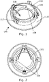
- Fig. 1 shows a line drawing of a downlight front 100 seen in perspective from above and from the side. More specifically, the figure shows a downlight front 100 that comprises a flange 102, where a light source can be flush with the flange, where there are two (only one cutout 104 visible in Fig. 1 ) in the part of the flange the light source can be flush with and where the one or more cutouts are arranged so that a light source can be flush against the flange in such a way that here are one or more through-going openings between the flange and the light source.
- the figure also shows a circularly symmetrical wall 106 which, together with the flange 102 forms a holder with a cavity that can secure a conical light source (such as a typical electrical LED light source, e.g., with a GU10 base) in the directions downwards and to all sides.
- the flange 104 is an inner flange that is turned inwards from wall 106. By virtue of the cavity in the middle of the flange, light from the light source can be emitted downwards through the holder.
- the springy elements are shown in the form of metallic elements 108 where the light source can be secured in a reversible manner against upward movement.
- FIG. 1 shows an outer flange 110 which can be flush against a downlight box (where "box” can be confused with “can”) and springy elements 112 that can secure the downlight front (against gravitational force) by securing to a downlight box.
- the directions “from above”, “from the side” and “from below” mean directions in the way the professional would understand them if the downlight front is installed in a lamp on a flat surface with the comparison specimen vertically downwards and where the lamp is intended to shine downwards (possibly at an angle in relation to vertically downward if the downlight front is tilted).
- Fig. 2 shows a line drawing of the downlight front 100 seen from above, i.e., from a point above the ceiling if the downlight front is installed in a ceiling.
- two cutouts 104 are visible in flange 102.
- Fig. 3 shows a line drawing of the downlight front 100 seen from the side.
- Fig. 4 shows a line drawing of downlight front 100 seen from below and from the side, i.e., from a point under the ceiling and thus the drawing shows downlight front 100 from a view an observer could have after installation (but without the light source being shown). Cutout 104 is visible from this angle but will not be visible from a vertical angle from below (corresponding to a view from the other side of the paper in Fig. 2 ) since cutouts 104 are not through-going.
- Fig. 5 shows a line drawing of the downlight front 100 seen from above and from the side, where flange 102 is tilted to one side.
- Fig. 6 shows a line drawing of downlight front 100 seen from above and from the side, where flange 102 is tilted to one side (in relation to Fig. 5 ).
- Figs. 5-6 thus show that the flange can be tilted around an axis and where both cutouts are located on the part of the flange against which the light source may be flush, which is furthest away from the axis. More specifically, the axis is located in such a way that a projection of the axis down on the flange's surface splits the flange into two equally sized circular halves and the cutouts are positioned at the top point, i.e., the furthest possible point in relation to the axis of each of the two parts.
- Liquid that has entered the cavity formed by wall 106 and flange 102 will, when tilted, be carried away from the axis due to gravitational force and down towards one or the other cutout, from which it can be drained away via the through-going opening between the flange and light source corresponding to the cutout.
- Fig. 7 shows a diagram of a cross section straight through an example that could be relevant to the understanding of embodiments of the invention and shows, in a more specific manner, a downlight lamp 726 seen from the side and installed in a construction element 722.
- the drawing shows downlight front 700 with (an inner) flange 702 with cutouts 704 and (an outer) flange 710.
- Downlight front 700 can be tilted around axis 728 (note that, in this embodiment, cutouts are in the same cross section as axis 728).
- Downlight front 700 is installed in a downlight box 720 that is then installed in construction element 722.
- the drawing furthermore shows a light source 718 in the form of a conical electrical LED light source with a GU10 base in the top 719 (base not shown).
- Light source 718 is secured by springy metal cable ties 708. The gravitational force is directed down the way as indicated by arrow 724.
- Flange 702 has an inner diameter 714 that is 43 mm and an outer diameter 716 that is 50 mm.
- a distance 712 between a flat surface such as the underside of light source 718 that is flush with flange 702 and the furthest away point of the one or more cutouts is 0.5 mm.
- Cutouts 704 are arranged in such a way that the one or more through-going openings between the flange and light source allow the passage of a liquid, as indicated by the dotted arrows.
- a light source 718 is secured where the downlight front 700 prevents movement of the light source downward 724 as a result of the light source being flush with flange 702, where there are one or more through-going openings between the flange and the light source.
- liquid is drained from one side of the one or more through-going openings (the side that is above flange 702) to the other side (the side that is under flange 702) of the one or more through-going openings by means of the liquid passing through the one or more through-going openings (as indicated by the dotted arrows).
- Fig. 8 shows an implementation of the invention and, more specifically, a light fitting 830 for installation in a panel 822, such as a panel with a cavity 850, where the light fitting comprises:
- the cable tie is (made of) flexible material in such a way that it can be bent (as indicated by the two-way arrow) when the light fitting needs to go through the opening in the panel.
- the light fitting is shown with 1 cable tie, while in a preferred embodiment there are at least 2 cable ties, such as the cable tie shown on the left-hand side and a second cable tie on the right-hand side, such as the two cable ties being positioned each on their own side, such as in positioned 180 degrees between them and/or as far from each other as possible.
- the possibility of 2 cable ties or more also applies to Figs. 9-15 and 21-22 .
- Light fitting 830 also contains an electrical connector (not shown in Fig. 8 , but is arranged as shown in Fig. 14 ) arranged in such a way that the electrical connector is accessible (exclusively) from a second side of the panel after installation.
- the box contains an opening 852, such as a through-going opening that is arranged in such a way that, after installation, the opening is or could be positioned outside the tensioned part of the cable tie.
- Fig. 8 light fitting 830 is shown below panel 822 and the arrow pointing vertically upward indicates that the light fitting can be inserted partially through cavity 850.
- Fig. 9 shows the situation where the light fitting is inserted partially through the cavity so that the primary flange arrangement 842 is flush against the (under-) side of panel 822.
- Fig. 10 shows that the cable tie has been moved downward through the ratchet mechanism in such a way that the flange arrangements 842, 844 have become closer to each other and are flush against each side of the panel (on first side 834 and second side 836 of the panel respectively) and - by virtue of the ratchet - lock the light fitting securely in relation to the panel.
- the scissors indicate that the tensioned part of the cable tie- between the secondary flange arrangement 844 and ratchet mechanism 840 - can be broken, such as cut across via the access through opening 852 from a first side of the panel (where it is understood that even if opening 852 is in principle on the other side of the panel, the opening - and thereby the tensioned part of the cable tie - can be accessed from the first side of the panel through the cavity).
- Fig. 12 shows a situation where the tensioned part of the cable tie is broken and the light fitting is therefore no longer secured and can be removed (as indicated by the arrow pointing downward), e.g., in connection with access being desired to a connector on the rear of the box in relation to the cavity.
- Fig. 13 shows an alternative embodiment of a light fitting 1330 (the same reference numbers refer to the same elements) with a box 1320, where the light fitting contains a ratchet mechanism part 1354 that is separate from the box and where the ratchet mechanism part is arranged in such a way that the ratchet mechanism part is accessible from a first side of the panel after installation.
- Panel 1322 is a bit thinner than panel 822 in Figs. 8-12 .
- the cable tie 1338 in Figure 13 is a bit different to the cable tie depicted in Figs.
- Fig. 13 light fitting 1330 is shown below panel 822 and the arrow pointing vertically upward indicates that the light fitting can be partially inserted through cavity 850.
- Fig. 14 shows an electrical connector 1450 (not shown in Fig. 13 , even if it is also present there) and that the light fitting 1330 is inserted partially through the cavity in the panel and secured in a similar way to Figs. 8-12 , apart from the fact that ratchet mechanism 1354 in Figs. 13-14 is separate and Fig. 14 is made to sit flush against a part 1348 of the box during installation, which, in this embodiment, is also a track that guides the separate ratchet mechanism's movement inside the box (in the figure, the upward movement that occurs between Figs. 13 and 14 ). In other embodiments, there is no part 1348 and the lock 1354 is instead directly flush with an inner surface of the box 1320.
- the scissors in Fig. 14 also indicate that the tensioned part of the cable tie can be broken from the first side of the panel in a similar way as in Fig. 11 and the light fitting thereby removed.
- Fig. 15 shows an alternative embodiment of a light fitting 1530 with a box 1520 corresponding to the box in Figs. 13-14 , apart from the fact that the box is flush with an inner surface of the box 1520 (and thus does not have an element corresponding to 1348).
- the cable tie is positioned outside the box's cavity, but it could also run entirely or partly inside the box's cavity (possible in a corresponding manner as in Figs. 13-15 ).
- Fig. 16 shows a light fitting 1630 with a sealing element 1660 and also a primary flange arrangement 1642, a secondary flange arrangement 1644, a box 1620 and an electrical connector 1650.
- Fig. 17 shows the light fitting 1630 as in Fig. 16 but with the sealing element 1660 shifted in direction towards the primary flange arrangement 1642.
- Fig. 18 shows the light fitting 1630 as in Figs. 16-17 installed in a panel 1622 by means of the sealing element and, more specifically therefore, that the sealing element 1660 is, under the influence of the secondary flange arrangement 1644, shifted in direction towards the primary flange arrangement 1642 in such a way that the primary flange arrangement 1642 and sealing element 1660 grip onto the panel 1622.
- Fig. 19 shows the light fitting 1630 as in Fig. 18 from a different angle.
- Fig. 20 shows (A) in the left-hand side an embodiment of a light fitting installed in a panel 2022 and where the light fitting comprises two cable ties (one cable tie on the right-hand side and one cable tie on the left-hand side) where the cable tie on the left-hand side is shifted in such a way that the secondary flange arrangement 2044a on the cable tie is flush with the upper side of panel 2022 and locks the light fitting around the panel together with the primary flange arrangement 2042a that is flush with the underside of the panel.
- Fig. 20 shows (B) in the right-hand side an embodiment of a light fitting installed in a panel 2022 and where the light fitting comprises two cable ties (one cable tie on the right hand side and one cable tie on the left-hand side) where the cable tie on the left-hand side is shifted in such a way that the secondary flange arrangement 2044b on the cable tie is flush with the upper side of the panel and locks the light fitting around the panel together with the primary flange arrangement 2042b that is flush with the underside of the panel (in the same way as in Sub-figure A on the left-hand side of Fig. 20 ).
- the figure also shows a sealing element 2060, (corresponding to sealing element 1660 in Figs.
- Fig. 21 shows an alternative embodiment of a light fitting 2130 (in relation to, for example the light fitting in Fig. 15 , but where the same reference numbers refer to the same elements) with a box 2120, where the light fitting contains a ratchet mechanism part 2154 that is separate from the box and where the ratchet mechanism part is arranged in such a way that the ratchet mechanism part is accessible from a first side of the panel after installation.
- a distance between the primary flange arrangement and the secondary flange arrangement can be increased in a non-destructive manner where no parts (or the cable tie either) are damaged.
- the ratchet mechanism being available from the first side and where a connection between the box and a ratchet mechanism part can be broken in a non-destructive manner, where neither the box nor the ratchet mechanism part are damaged.
- this is realized by means of a reversible click lock where the actual ratchet mechanism part contains spring-loaded elements (the right- and left-hand sides) where each contains a part (the triangular projection on the outer sides) that catch onto an element (the triangular cavities) on the box in such a way that the spring power keeps the spring-loaded element in a position where the ratchet mechanism part and the box are locked in relation to each other and where the two parts can be separated if the spring power is overcome.
- connection between the box and ratchet mechanism part can be released from the first side manually by means of ordinary fingers or a tool such as, for example, pliers that can press in on the sides of the ratchet mechanism part as indicated by the two opposing thick unbroken arrows.
- the light fitting can be removed by means of the catch between the cable tie and ratchet mechanism being released from the first side through the detent going through the catch with the cable tie being accessible from the first side and being able to be bent and/or shifted away from the cable tie by means of a cylindrical element that is at least 1 mm in diameter (as shown in the drawing as element 2162, that can be inserted in an upward direction up to the detent in the ratchet mechanism part).
- Fig. 22 shows a removal of light fitting 2130, where the box 2120 is taken down (as indicated by the open arrow) after the sides of the ratchet mechanism part 2154 have been pressed together as shown by the opposing arrow in Fig. 21 and/or the detent has been bent out of the catch with the cable tie from element 2162 in Fig. 21 .
Landscapes
- Engineering & Computer Science (AREA)
- General Engineering & Computer Science (AREA)
- Non-Portable Lighting Devices Or Systems Thereof (AREA)
- Arrangement Of Elements, Cooling, Sealing, Or The Like Of Lighting Devices (AREA)
Applications Claiming Priority (1)
| Application Number | Priority Date | Filing Date | Title |
|---|---|---|---|
| DKBA202000133U DK202000133U3 (da) | 2020-12-15 | 2020-12-15 | Belysningsarmatur med strips til montering og demontering |
Publications (1)
| Publication Number | Publication Date |
|---|---|
| EP4015902A1 true EP4015902A1 (fr) | 2022-06-22 |
Family
ID=81214439
Family Applications (1)
| Application Number | Title | Priority Date | Filing Date |
|---|---|---|---|
| EP21214573.4A Pending EP4015902A1 (fr) | 2020-12-15 | 2021-12-14 | Luminaire avec des bandes pour le montage et le démontage |
Country Status (3)
| Country | Link |
|---|---|
| EP (1) | EP4015902A1 (fr) |
| AU (1) | AU2021286303A1 (fr) |
| DK (1) | DK202000133U3 (fr) |
Citations (5)
| Publication number | Priority date | Publication date | Assignee | Title |
|---|---|---|---|---|
| EP1148292A2 (fr) * | 2000-04-22 | 2001-10-24 | A. Raymond & Cie | Dispositif de fixation d'une lampe à encastrer dans le plafond |
| US20060131046A1 (en) * | 2004-12-17 | 2006-06-22 | Sterling Design Group | Fastening system |
| US20100208471A1 (en) * | 2009-02-17 | 2010-08-19 | Sell Timothy L | Liner for recessed light housing |
| GB2530177A (en) * | 2014-09-09 | 2016-03-16 | B & W Group Ltd | Method and apparatus for installing an object in a recess |
| KR101855361B1 (ko) * | 2017-01-11 | 2018-05-08 | 주식회사 코지엘이디 | Gmp용 조명등기구 |
-
2020
- 2020-12-15 DK DKBA202000133U patent/DK202000133U3/da active IP Right Grant
-
2021
- 2021-12-14 EP EP21214573.4A patent/EP4015902A1/fr active Pending
- 2021-12-14 AU AU2021286303A patent/AU2021286303A1/en not_active Abandoned
Patent Citations (5)
| Publication number | Priority date | Publication date | Assignee | Title |
|---|---|---|---|---|
| EP1148292A2 (fr) * | 2000-04-22 | 2001-10-24 | A. Raymond & Cie | Dispositif de fixation d'une lampe à encastrer dans le plafond |
| US20060131046A1 (en) * | 2004-12-17 | 2006-06-22 | Sterling Design Group | Fastening system |
| US20100208471A1 (en) * | 2009-02-17 | 2010-08-19 | Sell Timothy L | Liner for recessed light housing |
| GB2530177A (en) * | 2014-09-09 | 2016-03-16 | B & W Group Ltd | Method and apparatus for installing an object in a recess |
| KR101855361B1 (ko) * | 2017-01-11 | 2018-05-08 | 주식회사 코지엘이디 | Gmp용 조명등기구 |
Also Published As
| Publication number | Publication date |
|---|---|
| DK202000133U3 (da) | 2022-03-17 |
| AU2021286303A1 (en) | 2022-06-30 |
Similar Documents
| Publication | Publication Date | Title |
|---|---|---|
| US7728226B2 (en) | Universal water-resistant cover assembly for an electrical outlet box | |
| CN102197557B (zh) | 机械式入线口 | |
| US10164415B2 (en) | Junction box of a recessed luminaire for installation in shallow spaces | |
| US20150085500A1 (en) | Recessed mini-can lighting assembly | |
| JP7337231B2 (ja) | 非常用の照明器具 | |
| US11050230B1 (en) | Electrical box for mounting an electrical device or fixture on a suspended ceiling T-bar or intersection of a T-bar grid | |
| CN1656650A (zh) | 安全模块配电系统 | |
| KR101168785B1 (ko) | 전기장치를 벽에 설치하기 위한 지지 프레임 | |
| JP6633856B2 (ja) | 照明器具の本体及び照明器具 | |
| EP4015902A1 (fr) | Luminaire avec des bandes pour le montage et le démontage | |
| JP2017033731A (ja) | 照明装置 | |
| US20080003871A1 (en) | Smoke-resistant surface mount box for plenum space | |
| JP6584848B2 (ja) | 照明器具及びバネ受け | |
| JP6679212B2 (ja) | 照明器具 | |
| JP2017033726A (ja) | 直管形ランプ及び照明装置 | |
| JP6468940B2 (ja) | 照明器具 | |
| JP6562710B2 (ja) | 光源ユニット及び照明器具 | |
| JP2020074337A (ja) | 照明器具 | |
| JP6681669B2 (ja) | 基板ユニット装置及び照明器具 | |
| JP2017033727A (ja) | 直管形ランプ及び照明装置 | |
| JP5695238B2 (ja) | Led照明装置 | |
| JP6727387B2 (ja) | 照明器具 | |
| JP6811831B2 (ja) | 照明器具の本体、照明器具の枠及び照明器具 | |
| JP6489928B2 (ja) | 基板ユニット装置及び照明器具 | |
| JP2017033725A (ja) | 直管形ランプ及び照明装置 |
Legal Events
| Date | Code | Title | Description |
|---|---|---|---|
| PUAI | Public reference made under article 153(3) epc to a published international application that has entered the european phase |
Free format text: ORIGINAL CODE: 0009012 |
|
| STAA | Information on the status of an ep patent application or granted ep patent |
Free format text: STATUS: THE APPLICATION HAS BEEN PUBLISHED |
|
| AK | Designated contracting states |
Kind code of ref document: A1 Designated state(s): AL AT BE BG CH CY CZ DE DK EE ES FI FR GB GR HR HU IE IS IT LI LT LU LV MC MK MT NL NO PL PT RO RS SE SI SK SM TR |
|
| STAA | Information on the status of an ep patent application or granted ep patent |
Free format text: STATUS: REQUEST FOR EXAMINATION WAS MADE |
|
| 17P | Request for examination filed |
Effective date: 20221222 |
|
| RBV | Designated contracting states (corrected) |
Designated state(s): AL AT BE BG CH CY CZ DE DK EE ES FI FR GB GR HR HU IE IS IT LI LT LU LV MC MK MT NL NO PL PT RO RS SE SI SK SM TR |
|
| STAA | Information on the status of an ep patent application or granted ep patent |
Free format text: STATUS: EXAMINATION IS IN PROGRESS |
|
| 17Q | First examination report despatched |
Effective date: 20240814 |