EP4015823B1 - Unité de moteur à piston rotatif pourvu de dispositif d'alimentation en lubrifiant - Google Patents
Unité de moteur à piston rotatif pourvu de dispositif d'alimentation en lubrifiant Download PDFInfo
- Publication number
- EP4015823B1 EP4015823B1 EP20214588.4A EP20214588A EP4015823B1 EP 4015823 B1 EP4015823 B1 EP 4015823B1 EP 20214588 A EP20214588 A EP 20214588A EP 4015823 B1 EP4015823 B1 EP 4015823B1
- Authority
- EP
- European Patent Office
- Prior art keywords
- lubricant
- positive displacement
- displacement machine
- pump
- rotary positive
- Prior art date
- Legal status (The legal status is an assumption and is not a legal conclusion. Google has not performed a legal analysis and makes no representation as to the accuracy of the status listed.)
- Active
Links
- 239000000314 lubricant Substances 0.000 title claims description 110
- 238000006073 displacement reaction Methods 0.000 claims description 26
- 238000011144 upstream manufacturing Methods 0.000 claims description 4
- 239000003921 oil Substances 0.000 description 24
- 230000001360 synchronised effect Effects 0.000 description 6
- 239000010687 lubricating oil Substances 0.000 description 4
- 238000010586 diagram Methods 0.000 description 2
- 239000007921 spray Substances 0.000 description 2
- 239000000443 aerosol Substances 0.000 description 1
- 238000002485 combustion reaction Methods 0.000 description 1
- 230000006835 compression Effects 0.000 description 1
- 238000007906 compression Methods 0.000 description 1
- 238000001816 cooling Methods 0.000 description 1
- 230000008878 coupling Effects 0.000 description 1
- 238000010168 coupling process Methods 0.000 description 1
- 238000005859 coupling reaction Methods 0.000 description 1
- 230000007423 decrease Effects 0.000 description 1
- 230000001419 dependent effect Effects 0.000 description 1
- 230000000694 effects Effects 0.000 description 1
- 239000007788 liquid Substances 0.000 description 1
- 238000005461 lubrication Methods 0.000 description 1
- 238000000034 method Methods 0.000 description 1
- 239000010688 mineral lubricating oil Substances 0.000 description 1
- 230000002093 peripheral effect Effects 0.000 description 1
- 238000005086 pumping Methods 0.000 description 1
- 239000010689 synthetic lubricating oil Substances 0.000 description 1
Images

Classifications
-
- F—MECHANICAL ENGINEERING; LIGHTING; HEATING; WEAPONS; BLASTING
- F04—POSITIVE - DISPLACEMENT MACHINES FOR LIQUIDS; PUMPS FOR LIQUIDS OR ELASTIC FLUIDS
- F04C—ROTARY-PISTON, OR OSCILLATING-PISTON, POSITIVE-DISPLACEMENT MACHINES FOR LIQUIDS; ROTARY-PISTON, OR OSCILLATING-PISTON, POSITIVE-DISPLACEMENT PUMPS
- F04C29/00—Component parts, details or accessories of pumps or pumping installations, not provided for in groups F04C18/00 - F04C28/00
- F04C29/02—Lubrication; Lubricant separation
- F04C29/025—Lubrication; Lubricant separation using a lubricant pump
-
- F—MECHANICAL ENGINEERING; LIGHTING; HEATING; WEAPONS; BLASTING
- F04—POSITIVE - DISPLACEMENT MACHINES FOR LIQUIDS; PUMPS FOR LIQUIDS OR ELASTIC FLUIDS
- F04B—POSITIVE-DISPLACEMENT MACHINES FOR LIQUIDS; PUMPS
- F04B17/00—Pumps characterised by combination with, or adaptation to, specific driving engines or motors
- F04B17/03—Pumps characterised by combination with, or adaptation to, specific driving engines or motors driven by electric motors
- F04B17/04—Pumps characterised by combination with, or adaptation to, specific driving engines or motors driven by electric motors using solenoids
-
- F—MECHANICAL ENGINEERING; LIGHTING; HEATING; WEAPONS; BLASTING
- F04—POSITIVE - DISPLACEMENT MACHINES FOR LIQUIDS; PUMPS FOR LIQUIDS OR ELASTIC FLUIDS
- F04B—POSITIVE-DISPLACEMENT MACHINES FOR LIQUIDS; PUMPS
- F04B53/00—Component parts, details or accessories not provided for in, or of interest apart from, groups F04B1/00 - F04B23/00 or F04B39/00 - F04B47/00
- F04B53/20—Filtering
-
- F—MECHANICAL ENGINEERING; LIGHTING; HEATING; WEAPONS; BLASTING
- F04—POSITIVE - DISPLACEMENT MACHINES FOR LIQUIDS; PUMPS FOR LIQUIDS OR ELASTIC FLUIDS
- F04C—ROTARY-PISTON, OR OSCILLATING-PISTON, POSITIVE-DISPLACEMENT MACHINES FOR LIQUIDS; ROTARY-PISTON, OR OSCILLATING-PISTON, POSITIVE-DISPLACEMENT PUMPS
- F04C23/00—Combinations of two or more pumps, each being of rotary-piston or oscillating-piston type, specially adapted for elastic fluids; Pumping installations specially adapted for elastic fluids; Multi-stage pumps specially adapted for elastic fluids
- F04C23/005—Combinations of two or more pumps, each being of rotary-piston or oscillating-piston type, specially adapted for elastic fluids; Pumping installations specially adapted for elastic fluids; Multi-stage pumps specially adapted for elastic fluids of dissimilar working principle
-
- F—MECHANICAL ENGINEERING; LIGHTING; HEATING; WEAPONS; BLASTING
- F04—POSITIVE - DISPLACEMENT MACHINES FOR LIQUIDS; PUMPS FOR LIQUIDS OR ELASTIC FLUIDS
- F04C—ROTARY-PISTON, OR OSCILLATING-PISTON, POSITIVE-DISPLACEMENT MACHINES FOR LIQUIDS; ROTARY-PISTON, OR OSCILLATING-PISTON, POSITIVE-DISPLACEMENT PUMPS
- F04C2/00—Rotary-piston machines or pumps
- F04C2/08—Rotary-piston machines or pumps of intermeshing-engagement type, i.e. with engagement of co-operating members similar to that of toothed gearing
-
- F—MECHANICAL ENGINEERING; LIGHTING; HEATING; WEAPONS; BLASTING
- F04—POSITIVE - DISPLACEMENT MACHINES FOR LIQUIDS; PUMPS FOR LIQUIDS OR ELASTIC FLUIDS
- F04C—ROTARY-PISTON, OR OSCILLATING-PISTON, POSITIVE-DISPLACEMENT MACHINES FOR LIQUIDS; ROTARY-PISTON, OR OSCILLATING-PISTON, POSITIVE-DISPLACEMENT PUMPS
- F04C2240/00—Components
- F04C2240/40—Electric motor
- F04C2240/401—Linear motor
-
- F—MECHANICAL ENGINEERING; LIGHTING; HEATING; WEAPONS; BLASTING
- F04—POSITIVE - DISPLACEMENT MACHINES FOR LIQUIDS; PUMPS FOR LIQUIDS OR ELASTIC FLUIDS
- F04C—ROTARY-PISTON, OR OSCILLATING-PISTON, POSITIVE-DISPLACEMENT MACHINES FOR LIQUIDS; ROTARY-PISTON, OR OSCILLATING-PISTON, POSITIVE-DISPLACEMENT PUMPS
- F04C2240/00—Components
- F04C2240/40—Electric motor
- F04C2240/403—Electric motor with inverter for speed control
-
- F—MECHANICAL ENGINEERING; LIGHTING; HEATING; WEAPONS; BLASTING
- F04—POSITIVE - DISPLACEMENT MACHINES FOR LIQUIDS; PUMPS FOR LIQUIDS OR ELASTIC FLUIDS
- F04C—ROTARY-PISTON, OR OSCILLATING-PISTON, POSITIVE-DISPLACEMENT MACHINES FOR LIQUIDS; ROTARY-PISTON, OR OSCILLATING-PISTON, POSITIVE-DISPLACEMENT PUMPS
- F04C2240/00—Components
- F04C2240/80—Other components
- F04C2240/808—Electronic circuits (e.g. inverters) installed inside the machine
-
- F—MECHANICAL ENGINEERING; LIGHTING; HEATING; WEAPONS; BLASTING
- F04—POSITIVE - DISPLACEMENT MACHINES FOR LIQUIDS; PUMPS FOR LIQUIDS OR ELASTIC FLUIDS
- F04C—ROTARY-PISTON, OR OSCILLATING-PISTON, POSITIVE-DISPLACEMENT MACHINES FOR LIQUIDS; ROTARY-PISTON, OR OSCILLATING-PISTON, POSITIVE-DISPLACEMENT PUMPS
- F04C2270/00—Control; Monitoring or safety arrangements
- F04C2270/10—Voltage
Definitions
- the invention relates to a rotary piston machine unit with a dry-running, twin-shaft rotary piston machine and a lubricant supply device.
- Rotary piston machines particularly screw compressors and rotary piston blowers of the Roots type, but also rotary piston expansion machines, are usually mainly mounted on roller bearings up to differential pressures of around 15 bar and up to speeds of around 20,000 rpm.
- the high radial forces that occur during the compression and expansion process are absorbed by cylindrical roller bearings, for example.
- a pressure gradient also forms in the axial direction, which also causes axial forces to occur in the bearings. Additional axial forces can also be caused, for example, by helical gears mounted on the rotor shafts.
- These highly loaded bearings must be supplied with sufficient lubricating oil.
- the bearings and synchronous wheels of such rotary piston machines are typically supplied with oil in one of three ways described below.
- oil pumps are used, which are often mechanically driven directly by one of the two shafts of the twin-shaft rotary piston machine.
- the size of the oil pump must be such that even at all operating points of the rotary piston machine with the lowest permissible speed, sufficient oil is pumped. This often means that at higher speeds, much more oil is pumped than is needed.
- the use of an oil pump has the advantage that larger quantities of oil can be sprayed into the bearings or other lubrication points via nozzles.
- so-called overflow regulators are often used to limit the outlet pressure of the oil pump. Even if the overflow regulator limits the pump's power consumption, it still requires an unnecessarily large amount of power at high speeds, which significantly reduces the overall efficiency of the rotary piston machine or rotary piston machine unit.
- One aim of the invention is to provide a rotary piston machine unit with a lubricant supply device, whereby the lubricant supply device itself consumes as little power as possible, whereby on the one hand the overall efficiency of the rotary piston machine unit is improved and on the other hand the average lubricant temperature is reduced. Furthermore, the operational reliability is to be increased and the service life of the lubricant and the bearings is to be increased.
- a rotary piston machine unit is provided with the features according to claim 1. Preferred embodiments are listed in the dependent claims. The invention further relates to the use of a lubricant supply device for a rotary piston machine.
- a rotary piston machine unit comprises a rotary piston machine as a mechanical unit in addition to other components, such as a main drive motor or a lubricant supply device.
- a rotary piston machine as a mechanical unit in addition to other components, such as a main drive motor or a lubricant supply device.
- the profiled areas of the rotors have no contact with each other due to the synchronization of the rotors by a synchronization gear arranged outside the conveying chamber.
- the rotors of the rotary piston machine are thus arranged for contact-free operation.
- the design as a dry-running rotary piston machine does not exclude that liquid media are nevertheless injected, for example to achieve cooling during operation.
- Such a rotary piston machine usually comprises two rotors mounted in a housing via shafts and bearing arrangements, which mesh with each other in opposite directions in order to define a conveying chamber together with the housing.
- One of the bearing arrangements of each shaft is designed as a fixed bearing arrangement in the axial direction.
- the task of the synchronous wheels is to allow the pair of rotors to rotate in opposite directions to each other with as little play as possible but without contact. The synchronous wheels transmit a significant torque.
- the bearings and/or the synchronous gear must be supplied with lubricant.
- the lubricated chambers in which the bearing arrangements and the synchronous wheels are located are separated from the pumping chamber by means of shaft seals, which are sometimes quite complex, so that the pumped medium does not come into contact with oil.
- the rotary piston machine unit comprises a dry-running, two-shaft rotary piston machine and a lubricant supply device, wherein the lubricant supply device comprises an electrically driven lubricant pump.
- the lubricant pump can be operated with a control voltage of the rotary piston machine unit, wherein the control voltage is ⁇ 50 V.
- the rotary piston machine unit has a control voltage power supply that provides an electrical supply to a control device of the rotary piston machine unit and the lubricant pump.
- a third voltage supply level can be avoided in this way, so that it is possible to only supply the To use the existing voltage levels of the rotary piston machine unit for the main drive motor and for the control voltage.
- the lubricant pump is preferably an oil pump.
- a mineral lubricating oil or a synthetic lubricating oil can be used as a lubricant.
- the lubricant pump of the lubricant supply device has the advantage that a continuous lubricant supply is ensured, whereby the complexity of the structure of the rotary piston machine unit is not increased by operation by means of the control voltage of the rotary piston machine.
- control voltage is direct current. This means that the control voltage commonly used in rotary piston machine units can be used.
- the electric lubricant pump driven by the control voltage is a positive displacement pump.
- Positive displacement pumps can also pump the lubricant at higher pressures.
- a preferred embodiment of a positive displacement lubricant pump is the gear pump.
- the lubricant pump is an oscillating armature pump with a pulse width modulator (PWM) connected upstream.
- PWM pulse width modulator
- vibrating armature pumps can be used even when hot lubricant or oil is used as the medium. function reliably and permanently, deliver a sufficient volume flow and consume very little power. For example, only around 50 W are required to supply lubricant to a rotary piston machine unit with a nominal output of 55 kW.
- Oscillating piston pumps are also known as solenoid pumps or oscillating piston pumps.
- the working principle of such pumps is based on a piston which is attracted by a magnetic field against the force of a spring and thus performs a lifting movement. After the magnetic field is switched off, the piston is moved back in the other direction by the spring force.
- Oscillating piston pumps are used, for example, in AT 275329 B , EP 0 288 216 B1 or EP 1 818 538 B1 revealed.
- the generation of a periodically present and non-existent magnetic field is usually realized by means of a coil through which current flows periodically.
- the lubricant pump is designed to be operated with a control voltage of ⁇ 30 V (in particular DC), e.g. 24 V (in particular DC).
- a pulse width modulator PWM
- DC direct current
- the rotary piston machine unit has a lubricant cooler to cool the lubricant.
- the lubricant cooler is arranged on the outlet side of the lubricant pump. This has the advantage that the still warm lubricant is pumped through the lubricant pump, thus enabling a higher volume flow.
- the rotary piston machine unit has a lubricant filter with which the circulating lubricant can be cleaned. It is particularly preferred to provide the lubricant filter on an inlet side of the lubricant pump. This protects the pump. In addition, the lubricant on the inlet side has a lower viscosity due to the heated state, so that the flow of the lubricant through the lubricant filter is less affected.
- the lubricant cooler and/or the lubricant filter also help to ensure that the lubricant has a relatively long service life. This means that a permanent and safe supply of lubricant can be provided.
- the use of a lubricant cooler and/or lubricant filter is not possible when using splash disks, splash rings or the like.
- the rotary piston machine unit has a supply line for conveying a lubricant from the lubricant pump to the bearings and a synchronization gear of the rotary piston machine and a return line for conveying a lubricant from the Bearings and a synchronization gear of the rotary piston machine to the lubricant pump.
- the rotary piston machine is a screw compressor.
- the invention relates to the use of a lubricant pump for supplying lubricant to a dry-running rotary piston machine, wherein the lubricant pump is operated with a control voltage of the rotary piston machine, wherein the control voltage is ⁇ 50 V.
- the control voltage is ⁇ 50 V.
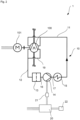
- a lubricant supply device 10 is integrated in a screw compressor unit 1 (as an example of a rotary piston machine unit).
- the screw compressor unit 1 comprises a screw compressor 100 (as an example of a rotary piston machine) and a main drive motor 101 which is used to drive the rotors of the screw compressor 100.
- the main drive motor 101 is supplied with a three-phase operating voltage of 400 V AC.
- the rotors of the screw compressor 100 are arranged for contact-free operation and are synchronized by means of a synchronization gear.
- the bearings and the synchronization gear are supplied with lubricant, in particular lubricating oil.
- lubricant supply device 10 according to the embodiment is used for this purpose.
- the lubricant supply device 10 comprises a supply line 11, which directs a lubricant flow to the screw compressor 100, and a return line 12, which is connected to the screw compressor 100 on a return side.
- a lubricant filter 13 is connected upstream of the lubricant pump 14, which cleans the lubricant supplied from the return line 12.
- the lubricant flows through a first connecting line 16 to the lubricant pump 14, which further conveys the lubricant.
- a feed line 18 is provided to supply lubricant to the lubricant circuit or to remove it from the lubricant circuit.
- the lubricant delivered by the lubricant pump 14 is fed to a lubricant cooler 15 via a second connecting line 17 in order to cool the lubricant after it has exited the lubricant pump 14.
- An outlet of the lubricant cooler 15 is connected to the supply line 11 through which the lubricant is fed to the screw compressor 100.
- Fig.1 not visible, but in Fig.2 As shown, the lubricant is distributed within the screw compressor to both bearing sides of the rotors.
- a coupling line 19 is provided on the screw compressor 100 to transfer the returning lubricant from one bearing side (in Fig.1 the drive side) to another bearing side of the screw compressor 100.
- the other bearing side of the screw compressor 100 is connected to the Return line 12 to close the lubricant circuit.
- the lubricant pump 14 is operated with a control voltage for the screw compressor unit 1 of 24 V DC.
- a pulse width modulator (PWM) 21 is provided for the operation of the lubricant pump 14, which is preceded by a power supply unit 20.
- the power supply unit 20 is usually supplied with an operating voltage of 400 V AC and converts the operating voltage of 400 V AC into direct voltage (typically 24 V DC).
- the power supply unit 20 provides, among other things, an electrical supply to a control device 22 of the rotary piston machine unit 1, and in particular to the lubricant pump 14.
- the pulse width modulator 21 receives the direct current (DC) provided by the power supply 20 and converts it into square-wave pulses.
- the pulses are used to periodically excite a coil of the lubricant pump 14, whose magnetic field acts on an oscillating armature.
- the lubricant pump thus operates at the frequency of the voltage supplied by the pulse width modulator 21.
Landscapes
- Engineering & Computer Science (AREA)
- Mechanical Engineering (AREA)
- General Engineering & Computer Science (AREA)
- General Details Of Gearings (AREA)
- Lubrication Of Internal Combustion Engines (AREA)
Claims (15)
- Unité de moteur à piston rotatif (1) avec un moteur (100) à piston rotatif à deux arbres, fonctionnant à sec, et un dispositif (10) d'alimentation en lubrifiant, dans laquelle le dispositif (10) d'alimentation en lubrifiant comprend une pompe de lubrifiant (14) entraînée de manière électrique, caractérisée en ce que la pompe de lubrifiant (14) peut fonctionner avec une tension de commande de l'unité de moteur à piston rotatif (1), dans laquelle la tension de commande est < 50 V et l'unité de moteur à piston rotatif présente un bloc d'alimentation de tension de commande, qui fournit une alimentation électrique à un dispositif de commande de l'unité de moteur à piston rotatif et à la pompe de lubrifiant.
- Unité de moteur à piston rotatif (1) selon la revendication 1, caractérisée en ce que la tension de commande est une tension continue.
- Unité de moteur à piston rotatif (1) selon la revendication 1 ou la revendication 2, caractérisée en ce que la pompe de lubrifiant (14) est une pompe volumétrique.
- Unité de moteur à piston rotatif (1) selon l'une quelconque des revendications précédentes, caractérisée en ce que la pompe de lubrifiant (14) est une pompe à armature oscillante.
- Unité de moteur à piston rotatif (1) selon la revendication 4, caractérisée en ce que la pompe de lubrifiant (14) est une pompe à armature oscillante avec un modulateur de largeur d'impulsion (21) monté en amont.
- Unité de moteur à piston rotatif (1) selon l'une quelconque des revendications 1 à 3, caractérisée en ce que la pompe de lubrifiant (14) est une pompe à engrenage.
- Unité de moteur à piston rotatif (1) selon l'une quelconque des revendications précédentes, caractérisée en ce que l'unité de moteur à piston rotatif (1) est conçue pour une puissance connectée ≤ 110 kW, de préférence ≤ 60 kW.
- Unité de moteur à piston rotatif (1) selon l'une quelconque des revendications précédentes, caractérisée en ce que la tension de commande est < 30 V.
- Unité de moteur à piston rotatif (1) selon l'une quelconque des revendications précédentes, comprenant en outre un refroidisseur de lubrifiant (15) qui est disposé en particulier au niveau d'un côté de sortie de la pompe de lubrifiant (14).
- Unité de moteur à piston rotatif (1) selon l'une quelconque des revendications précédentes, comprenant en outre un filtre de lubrifiant (13) qui est disposé en particulier au niveau d'un côté d'entrée de la pompe de lubrifiant (14).
- Unité de moteur à piston rotatif (1) selon l'une quelconque des revendications précédentes, comprenant une conduite d'amenée (11) pour le transport d'un lubrifiant de la pompe de lubrifiant (14) à un palier et/ou un engrenage de synchronisation du moteur (100) à piston rotatif ainsi qu'une conduite de retour (12) pour le transport d'un lubrifiant d'un palier et/ou d'un engrenage de synchronisation du moteur (100) à piston rotatif à la pompe de lubrifiant (14).
- Unité de moteur à piston rotatif (1) selon l'une quelconque des revendications précédentes, dans laquelle le moteur (100) à piston rotatif est un compresseur à vis à deux arbres.
- Utilisation d'une pompe de lubrifiant (14) pour une alimentation en lubrifiant d'un moteur (100) à piston rotatif fonctionnant à sec, dans laquelle la pompe de lubrifiant (14) fonctionne avec une tension de commande d'un bloc d'alimentation de tension de commande de l'unité de moteur à piston rotatif (1), la tension de commande étant < 50 V, de préférence < 30 V.
- Utilisation selon la revendication 13, dans laquelle la pompe de lubrifiant (14) fonctionne avec du courant continu.
- Utilisation selon l'une quelconque des revendications 13 à 14, dans laquelle la pompe de lubrifiant (14) est une pompe à armature oscillante, de préférence une pompe à armature oscillante avec un modulateur de largeur d'impulsion (21) monté en amont.
Priority Applications (1)
| Application Number | Priority Date | Filing Date | Title |
|---|---|---|---|
| EP20214588.4A EP4015823B1 (fr) | 2020-12-16 | 2020-12-16 | Unité de moteur à piston rotatif pourvu de dispositif d'alimentation en lubrifiant |
Applications Claiming Priority (1)
| Application Number | Priority Date | Filing Date | Title |
|---|---|---|---|
| EP20214588.4A EP4015823B1 (fr) | 2020-12-16 | 2020-12-16 | Unité de moteur à piston rotatif pourvu de dispositif d'alimentation en lubrifiant |
Publications (2)
| Publication Number | Publication Date |
|---|---|
| EP4015823A1 EP4015823A1 (fr) | 2022-06-22 |
| EP4015823B1 true EP4015823B1 (fr) | 2024-08-21 |
Family
ID=73855090
Family Applications (1)
| Application Number | Title | Priority Date | Filing Date |
|---|---|---|---|
| EP20214588.4A Active EP4015823B1 (fr) | 2020-12-16 | 2020-12-16 | Unité de moteur à piston rotatif pourvu de dispositif d'alimentation en lubrifiant |
Country Status (1)
| Country | Link |
|---|---|
| EP (1) | EP4015823B1 (fr) |
Families Citing this family (1)
| Publication number | Priority date | Publication date | Assignee | Title |
|---|---|---|---|---|
| CN115681474B (zh) * | 2022-11-29 | 2023-03-10 | 泉州博易盛科技有限公司 | 一种润滑油可循环利用的涡轮蜗杆减速器 |
Family Cites Families (8)
| Publication number | Priority date | Publication date | Assignee | Title |
|---|---|---|---|---|
| CH447818A (de) | 1967-02-21 | 1967-11-30 | Glutz Blotzheim Nachfolger Ag | Elektromagnetische Schwingankerpumpe |
| DE3744665A1 (de) * | 1986-10-14 | 1988-06-01 | Orbital Eng Pty | Pumpe |
| GB8709082D0 (en) | 1987-04-15 | 1987-05-20 | Eaton Sa Monaco | Electrical fluid pump |
| US20070248475A1 (en) | 2006-02-10 | 2007-10-25 | Defond Components Limited | Fluid pump |
| EP1855009B1 (fr) | 2006-05-11 | 2008-12-03 | Aerzener Maschinenfabrik GmbH | Machine rotative à lobes |
| CN107076127B (zh) * | 2014-06-09 | 2019-11-12 | 新尼杰特公司 | 用于冷却螺线管泵的螺线管线圈的方法和设备 |
| WO2016136482A1 (fr) * | 2015-02-25 | 2016-09-01 | 株式会社日立産機システム | Compresseur sans huile |
| DE102019201367A1 (de) * | 2019-02-04 | 2020-08-06 | Brose Fahrzeugteile SE & Co. Kommanditgesellschaft, Würzburg | Antrieb eines Nebenaggregats |
-
2020
- 2020-12-16 EP EP20214588.4A patent/EP4015823B1/fr active Active
Also Published As
| Publication number | Publication date |
|---|---|
| EP4015823A1 (fr) | 2022-06-22 |
Similar Documents
| Publication | Publication Date | Title |
|---|---|---|
| EP1521904B1 (fr) | Dispositif pour l'entrainement d'une pompe a agent de refroidissement | |
| EP1907704B1 (fr) | Compresseur a injection d'huile dote de moyens de reglage de la temperature de l'huile | |
| EP1070848B1 (fr) | Machine à déplacement positif pour des fluides compressibles | |
| DE69504961T2 (de) | Verdichter | |
| DE2801206A1 (de) | Spiralartige einrichtung mit einem festen gekroepften kurbelantriebsmechanismus | |
| EP3362652B1 (fr) | Dispositif de transport pour véhicule automobile | |
| DE3730966A1 (de) | Hermetisch geschlossener kompressor mit horizontaler antriebswelle | |
| DE102017130739A1 (de) | Hilfsantriebssystem für eine Pumpe | |
| EP1443210B1 (fr) | Groupe moto-pompe | |
| EP3371423B1 (fr) | Dispositif de refoulement pour le refoulement d'huile | |
| EP4015823B1 (fr) | Unité de moteur à piston rotatif pourvu de dispositif d'alimentation en lubrifiant | |
| EP4388199A1 (fr) | Compresseur à entraînement électrique à étages multiples | |
| DE2826071A1 (de) | Fluessigkeitspumpe der spiral-bauart | |
| WO2011035972A1 (fr) | Pompe d'alimentation électrique, et procédé permettant de faire fonctionner une pompe d'alimentation électrique | |
| DE102011004960A1 (de) | Kompressor, Druckluftanlage und Verfahren zur Druckluftversorgung | |
| EP1911964A1 (fr) | Pompe à carburant haute pression et système d'injection de carburant pour moteur à combustion interne | |
| DE102012112618B3 (de) | Mehrfachpumpe | |
| EP2558725B1 (fr) | Pompe de refoulement électrique et procédé d'entraînement d'une telle pompe | |
| DE112015003595T5 (de) | Integrierte Doppelpumpe für organische Arbeitsflüssigkeit | |
| DE102016225196C5 (de) | Elektromotorische Ölpumpe | |
| DE102020200256B4 (de) | Scrollverdichter | |
| WO2011101064A2 (fr) | Entraînement pour un compresseur à broches | |
| DE102013021254A1 (de) | Scroll-Maschine und Verfahren zu deren Betrieb | |
| EP0940622B1 (fr) | Pompe à huile | |
| DE102015005343A1 (de) | Pumpenanordnung für ein Kraftfahrzeug |
Legal Events
| Date | Code | Title | Description |
|---|---|---|---|
| PUAI | Public reference made under article 153(3) epc to a published international application that has entered the european phase |
Free format text: ORIGINAL CODE: 0009012 |
|
| STAA | Information on the status of an ep patent application or granted ep patent |
Free format text: STATUS: THE APPLICATION HAS BEEN PUBLISHED |
|
| AK | Designated contracting states |
Kind code of ref document: A1 Designated state(s): AL AT BE BG CH CY CZ DE DK EE ES FI FR GB GR HR HU IE IS IT LI LT LU LV MC MK MT NL NO PL PT RO RS SE SI SK SM TR |
|
| STAA | Information on the status of an ep patent application or granted ep patent |
Free format text: STATUS: REQUEST FOR EXAMINATION WAS MADE |
|
| 17P | Request for examination filed |
Effective date: 20221123 |
|
| RBV | Designated contracting states (corrected) |
Designated state(s): AL AT BE BG CH CY CZ DE DK EE ES FI FR GB GR HR HU IE IS IT LI LT LU LV MC MK MT NL NO PL PT RO RS SE SI SK SM TR |
|
| GRAP | Despatch of communication of intention to grant a patent |
Free format text: ORIGINAL CODE: EPIDOSNIGR1 |
|
| STAA | Information on the status of an ep patent application or granted ep patent |
Free format text: STATUS: GRANT OF PATENT IS INTENDED |
|
| INTG | Intention to grant announced |
Effective date: 20240320 |
|
| GRAS | Grant fee paid |
Free format text: ORIGINAL CODE: EPIDOSNIGR3 |
|
| GRAA | (expected) grant |
Free format text: ORIGINAL CODE: 0009210 |
|
| STAA | Information on the status of an ep patent application or granted ep patent |
Free format text: STATUS: THE PATENT HAS BEEN GRANTED |
|
| AK | Designated contracting states |
Kind code of ref document: B1 Designated state(s): AL AT BE BG CH CY CZ DE DK EE ES FI FR GB GR HR HU IE IS IT LI LT LU LV MC MK MT NL NO PL PT RO RS SE SI SK SM TR |
|
| REG | Reference to a national code |
Ref country code: GB Ref legal event code: FG4D Free format text: NOT ENGLISH |
|
| REG | Reference to a national code |
Ref country code: CH Ref legal event code: EP |
|
| REG | Reference to a national code |
Ref country code: IE Ref legal event code: FG4D Free format text: LANGUAGE OF EP DOCUMENT: GERMAN |
|
| REG | Reference to a national code |
Ref country code: DE Ref legal event code: R096 Ref document number: 502020008925 Country of ref document: DE |