EP4015823B1 - Drehkolbenmaschinenaggregat mit schmiermittelversorgungseinrichtung - Google Patents
Drehkolbenmaschinenaggregat mit schmiermittelversorgungseinrichtung Download PDFInfo
- Publication number
- EP4015823B1 EP4015823B1 EP20214588.4A EP20214588A EP4015823B1 EP 4015823 B1 EP4015823 B1 EP 4015823B1 EP 20214588 A EP20214588 A EP 20214588A EP 4015823 B1 EP4015823 B1 EP 4015823B1
- Authority
- EP
- European Patent Office
- Prior art keywords
- lubricant
- positive displacement
- displacement machine
- pump
- rotary positive
- Prior art date
- Legal status (The legal status is an assumption and is not a legal conclusion. Google has not performed a legal analysis and makes no representation as to the accuracy of the status listed.)
- Active
Links
Images

Classifications
-
- F—MECHANICAL ENGINEERING; LIGHTING; HEATING; WEAPONS; BLASTING
- F04—POSITIVE - DISPLACEMENT MACHINES FOR LIQUIDS; PUMPS FOR LIQUIDS OR ELASTIC FLUIDS
- F04C—ROTARY-PISTON, OR OSCILLATING-PISTON, POSITIVE-DISPLACEMENT MACHINES FOR LIQUIDS; ROTARY-PISTON, OR OSCILLATING-PISTON, POSITIVE-DISPLACEMENT PUMPS
- F04C29/00—Component parts, details or accessories of pumps or pumping installations, not provided for in groups F04C18/00 - F04C28/00
- F04C29/02—Lubrication; Lubricant separation
- F04C29/025—Lubrication; Lubricant separation using a lubricant pump
-
- F—MECHANICAL ENGINEERING; LIGHTING; HEATING; WEAPONS; BLASTING
- F04—POSITIVE - DISPLACEMENT MACHINES FOR LIQUIDS; PUMPS FOR LIQUIDS OR ELASTIC FLUIDS
- F04B—POSITIVE-DISPLACEMENT MACHINES FOR LIQUIDS; PUMPS
- F04B17/00—Pumps characterised by combination with, or adaptation to, specific driving engines or motors
- F04B17/03—Pumps characterised by combination with, or adaptation to, specific driving engines or motors driven by electric motors
- F04B17/04—Pumps characterised by combination with, or adaptation to, specific driving engines or motors driven by electric motors using solenoids
-
- F—MECHANICAL ENGINEERING; LIGHTING; HEATING; WEAPONS; BLASTING
- F04—POSITIVE - DISPLACEMENT MACHINES FOR LIQUIDS; PUMPS FOR LIQUIDS OR ELASTIC FLUIDS
- F04B—POSITIVE-DISPLACEMENT MACHINES FOR LIQUIDS; PUMPS
- F04B53/00—Component parts, details or accessories not provided for in, or of interest apart from, groups F04B1/00 - F04B23/00 or F04B39/00 - F04B47/00
- F04B53/20—Filtering
-
- F—MECHANICAL ENGINEERING; LIGHTING; HEATING; WEAPONS; BLASTING
- F04—POSITIVE - DISPLACEMENT MACHINES FOR LIQUIDS; PUMPS FOR LIQUIDS OR ELASTIC FLUIDS
- F04C—ROTARY-PISTON, OR OSCILLATING-PISTON, POSITIVE-DISPLACEMENT MACHINES FOR LIQUIDS; ROTARY-PISTON, OR OSCILLATING-PISTON, POSITIVE-DISPLACEMENT PUMPS
- F04C23/00—Combinations of two or more pumps, each being of rotary-piston or oscillating-piston type, specially adapted for elastic fluids; Pumping installations specially adapted for elastic fluids; Multi-stage pumps specially adapted for elastic fluids
- F04C23/005—Combinations of two or more pumps, each being of rotary-piston or oscillating-piston type, specially adapted for elastic fluids; Pumping installations specially adapted for elastic fluids; Multi-stage pumps specially adapted for elastic fluids of dissimilar working principle
-
- F—MECHANICAL ENGINEERING; LIGHTING; HEATING; WEAPONS; BLASTING
- F04—POSITIVE - DISPLACEMENT MACHINES FOR LIQUIDS; PUMPS FOR LIQUIDS OR ELASTIC FLUIDS
- F04C—ROTARY-PISTON, OR OSCILLATING-PISTON, POSITIVE-DISPLACEMENT MACHINES FOR LIQUIDS; ROTARY-PISTON, OR OSCILLATING-PISTON, POSITIVE-DISPLACEMENT PUMPS
- F04C2/00—Rotary-piston machines or pumps
- F04C2/08—Rotary-piston machines or pumps of intermeshing-engagement type, i.e. with engagement of co-operating members similar to that of toothed gearing
-
- F—MECHANICAL ENGINEERING; LIGHTING; HEATING; WEAPONS; BLASTING
- F04—POSITIVE - DISPLACEMENT MACHINES FOR LIQUIDS; PUMPS FOR LIQUIDS OR ELASTIC FLUIDS
- F04C—ROTARY-PISTON, OR OSCILLATING-PISTON, POSITIVE-DISPLACEMENT MACHINES FOR LIQUIDS; ROTARY-PISTON, OR OSCILLATING-PISTON, POSITIVE-DISPLACEMENT PUMPS
- F04C2240/00—Components
- F04C2240/40—Electric motor
- F04C2240/401—Linear motor
-
- F—MECHANICAL ENGINEERING; LIGHTING; HEATING; WEAPONS; BLASTING
- F04—POSITIVE - DISPLACEMENT MACHINES FOR LIQUIDS; PUMPS FOR LIQUIDS OR ELASTIC FLUIDS
- F04C—ROTARY-PISTON, OR OSCILLATING-PISTON, POSITIVE-DISPLACEMENT MACHINES FOR LIQUIDS; ROTARY-PISTON, OR OSCILLATING-PISTON, POSITIVE-DISPLACEMENT PUMPS
- F04C2240/00—Components
- F04C2240/40—Electric motor
- F04C2240/403—Electric motor with inverter for speed control
-
- F—MECHANICAL ENGINEERING; LIGHTING; HEATING; WEAPONS; BLASTING
- F04—POSITIVE - DISPLACEMENT MACHINES FOR LIQUIDS; PUMPS FOR LIQUIDS OR ELASTIC FLUIDS
- F04C—ROTARY-PISTON, OR OSCILLATING-PISTON, POSITIVE-DISPLACEMENT MACHINES FOR LIQUIDS; ROTARY-PISTON, OR OSCILLATING-PISTON, POSITIVE-DISPLACEMENT PUMPS
- F04C2240/00—Components
- F04C2240/80—Other components
- F04C2240/808—Electronic circuits (e.g. inverters) installed inside the machine
-
- F—MECHANICAL ENGINEERING; LIGHTING; HEATING; WEAPONS; BLASTING
- F04—POSITIVE - DISPLACEMENT MACHINES FOR LIQUIDS; PUMPS FOR LIQUIDS OR ELASTIC FLUIDS
- F04C—ROTARY-PISTON, OR OSCILLATING-PISTON, POSITIVE-DISPLACEMENT MACHINES FOR LIQUIDS; ROTARY-PISTON, OR OSCILLATING-PISTON, POSITIVE-DISPLACEMENT PUMPS
- F04C2270/00—Control; Monitoring or safety arrangements
- F04C2270/10—Voltage
Definitions
- the invention relates to a rotary piston machine unit with a dry-running, twin-shaft rotary piston machine and a lubricant supply device.
- Rotary piston machines particularly screw compressors and rotary piston blowers of the Roots type, but also rotary piston expansion machines, are usually mainly mounted on roller bearings up to differential pressures of around 15 bar and up to speeds of around 20,000 rpm.
- the high radial forces that occur during the compression and expansion process are absorbed by cylindrical roller bearings, for example.
- a pressure gradient also forms in the axial direction, which also causes axial forces to occur in the bearings. Additional axial forces can also be caused, for example, by helical gears mounted on the rotor shafts.
- These highly loaded bearings must be supplied with sufficient lubricating oil.
- the bearings and synchronous wheels of such rotary piston machines are typically supplied with oil in one of three ways described below.
- oil pumps are used, which are often mechanically driven directly by one of the two shafts of the twin-shaft rotary piston machine.
- the size of the oil pump must be such that even at all operating points of the rotary piston machine with the lowest permissible speed, sufficient oil is pumped. This often means that at higher speeds, much more oil is pumped than is needed.
- the use of an oil pump has the advantage that larger quantities of oil can be sprayed into the bearings or other lubrication points via nozzles.
- so-called overflow regulators are often used to limit the outlet pressure of the oil pump. Even if the overflow regulator limits the pump's power consumption, it still requires an unnecessarily large amount of power at high speeds, which significantly reduces the overall efficiency of the rotary piston machine or rotary piston machine unit.
- One aim of the invention is to provide a rotary piston machine unit with a lubricant supply device, whereby the lubricant supply device itself consumes as little power as possible, whereby on the one hand the overall efficiency of the rotary piston machine unit is improved and on the other hand the average lubricant temperature is reduced. Furthermore, the operational reliability is to be increased and the service life of the lubricant and the bearings is to be increased.
- a rotary piston machine unit is provided with the features according to claim 1. Preferred embodiments are listed in the dependent claims. The invention further relates to the use of a lubricant supply device for a rotary piston machine.
- a rotary piston machine unit comprises a rotary piston machine as a mechanical unit in addition to other components, such as a main drive motor or a lubricant supply device.
- a rotary piston machine as a mechanical unit in addition to other components, such as a main drive motor or a lubricant supply device.
- the profiled areas of the rotors have no contact with each other due to the synchronization of the rotors by a synchronization gear arranged outside the conveying chamber.
- the rotors of the rotary piston machine are thus arranged for contact-free operation.
- the design as a dry-running rotary piston machine does not exclude that liquid media are nevertheless injected, for example to achieve cooling during operation.
- Such a rotary piston machine usually comprises two rotors mounted in a housing via shafts and bearing arrangements, which mesh with each other in opposite directions in order to define a conveying chamber together with the housing.
- One of the bearing arrangements of each shaft is designed as a fixed bearing arrangement in the axial direction.
- the task of the synchronous wheels is to allow the pair of rotors to rotate in opposite directions to each other with as little play as possible but without contact. The synchronous wheels transmit a significant torque.
- the bearings and/or the synchronous gear must be supplied with lubricant.
- the lubricated chambers in which the bearing arrangements and the synchronous wheels are located are separated from the pumping chamber by means of shaft seals, which are sometimes quite complex, so that the pumped medium does not come into contact with oil.
- the rotary piston machine unit comprises a dry-running, two-shaft rotary piston machine and a lubricant supply device, wherein the lubricant supply device comprises an electrically driven lubricant pump.
- the lubricant pump can be operated with a control voltage of the rotary piston machine unit, wherein the control voltage is ⁇ 50 V.
- the rotary piston machine unit has a control voltage power supply that provides an electrical supply to a control device of the rotary piston machine unit and the lubricant pump.
- a third voltage supply level can be avoided in this way, so that it is possible to only supply the To use the existing voltage levels of the rotary piston machine unit for the main drive motor and for the control voltage.
- the lubricant pump is preferably an oil pump.
- a mineral lubricating oil or a synthetic lubricating oil can be used as a lubricant.
- the lubricant pump of the lubricant supply device has the advantage that a continuous lubricant supply is ensured, whereby the complexity of the structure of the rotary piston machine unit is not increased by operation by means of the control voltage of the rotary piston machine.
- control voltage is direct current. This means that the control voltage commonly used in rotary piston machine units can be used.
- the electric lubricant pump driven by the control voltage is a positive displacement pump.
- Positive displacement pumps can also pump the lubricant at higher pressures.
- a preferred embodiment of a positive displacement lubricant pump is the gear pump.
- the lubricant pump is an oscillating armature pump with a pulse width modulator (PWM) connected upstream.
- PWM pulse width modulator
- vibrating armature pumps can be used even when hot lubricant or oil is used as the medium. function reliably and permanently, deliver a sufficient volume flow and consume very little power. For example, only around 50 W are required to supply lubricant to a rotary piston machine unit with a nominal output of 55 kW.
- Oscillating piston pumps are also known as solenoid pumps or oscillating piston pumps.
- the working principle of such pumps is based on a piston which is attracted by a magnetic field against the force of a spring and thus performs a lifting movement. After the magnetic field is switched off, the piston is moved back in the other direction by the spring force.
- Oscillating piston pumps are used, for example, in AT 275329 B , EP 0 288 216 B1 or EP 1 818 538 B1 revealed.
- the generation of a periodically present and non-existent magnetic field is usually realized by means of a coil through which current flows periodically.
- the lubricant pump is designed to be operated with a control voltage of ⁇ 30 V (in particular DC), e.g. 24 V (in particular DC).
- a pulse width modulator PWM
- DC direct current
- the rotary piston machine unit has a lubricant cooler to cool the lubricant.
- the lubricant cooler is arranged on the outlet side of the lubricant pump. This has the advantage that the still warm lubricant is pumped through the lubricant pump, thus enabling a higher volume flow.
- the rotary piston machine unit has a lubricant filter with which the circulating lubricant can be cleaned. It is particularly preferred to provide the lubricant filter on an inlet side of the lubricant pump. This protects the pump. In addition, the lubricant on the inlet side has a lower viscosity due to the heated state, so that the flow of the lubricant through the lubricant filter is less affected.
- the lubricant cooler and/or the lubricant filter also help to ensure that the lubricant has a relatively long service life. This means that a permanent and safe supply of lubricant can be provided.
- the use of a lubricant cooler and/or lubricant filter is not possible when using splash disks, splash rings or the like.
- the rotary piston machine unit has a supply line for conveying a lubricant from the lubricant pump to the bearings and a synchronization gear of the rotary piston machine and a return line for conveying a lubricant from the Bearings and a synchronization gear of the rotary piston machine to the lubricant pump.
- the rotary piston machine is a screw compressor.
- the invention relates to the use of a lubricant pump for supplying lubricant to a dry-running rotary piston machine, wherein the lubricant pump is operated with a control voltage of the rotary piston machine, wherein the control voltage is ⁇ 50 V.
- the control voltage is ⁇ 50 V.
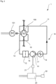
- a lubricant supply device 10 is integrated in a screw compressor unit 1 (as an example of a rotary piston machine unit).
- the screw compressor unit 1 comprises a screw compressor 100 (as an example of a rotary piston machine) and a main drive motor 101 which is used to drive the rotors of the screw compressor 100.
- the main drive motor 101 is supplied with a three-phase operating voltage of 400 V AC.
- the rotors of the screw compressor 100 are arranged for contact-free operation and are synchronized by means of a synchronization gear.
- the bearings and the synchronization gear are supplied with lubricant, in particular lubricating oil.
- lubricant supply device 10 according to the embodiment is used for this purpose.
- the lubricant supply device 10 comprises a supply line 11, which directs a lubricant flow to the screw compressor 100, and a return line 12, which is connected to the screw compressor 100 on a return side.
- a lubricant filter 13 is connected upstream of the lubricant pump 14, which cleans the lubricant supplied from the return line 12.
- the lubricant flows through a first connecting line 16 to the lubricant pump 14, which further conveys the lubricant.
- a feed line 18 is provided to supply lubricant to the lubricant circuit or to remove it from the lubricant circuit.
- the lubricant delivered by the lubricant pump 14 is fed to a lubricant cooler 15 via a second connecting line 17 in order to cool the lubricant after it has exited the lubricant pump 14.
- An outlet of the lubricant cooler 15 is connected to the supply line 11 through which the lubricant is fed to the screw compressor 100.
- Fig.1 not visible, but in Fig.2 As shown, the lubricant is distributed within the screw compressor to both bearing sides of the rotors.
- a coupling line 19 is provided on the screw compressor 100 to transfer the returning lubricant from one bearing side (in Fig.1 the drive side) to another bearing side of the screw compressor 100.
- the other bearing side of the screw compressor 100 is connected to the Return line 12 to close the lubricant circuit.
- the lubricant pump 14 is operated with a control voltage for the screw compressor unit 1 of 24 V DC.
- a pulse width modulator (PWM) 21 is provided for the operation of the lubricant pump 14, which is preceded by a power supply unit 20.
- the power supply unit 20 is usually supplied with an operating voltage of 400 V AC and converts the operating voltage of 400 V AC into direct voltage (typically 24 V DC).
- the power supply unit 20 provides, among other things, an electrical supply to a control device 22 of the rotary piston machine unit 1, and in particular to the lubricant pump 14.
- the pulse width modulator 21 receives the direct current (DC) provided by the power supply 20 and converts it into square-wave pulses.
- the pulses are used to periodically excite a coil of the lubricant pump 14, whose magnetic field acts on an oscillating armature.
- the lubricant pump thus operates at the frequency of the voltage supplied by the pulse width modulator 21.
Landscapes
- Engineering & Computer Science (AREA)
- Mechanical Engineering (AREA)
- General Engineering & Computer Science (AREA)
- General Details Of Gearings (AREA)
- Lubrication Of Internal Combustion Engines (AREA)
Description
- Die Erfindung betrifft ein Drehkolbenmaschinenaggregat mit einer trockenlaufenden, zweiwelligen Drehkolbenmaschine und einer Schmiermittelversorgungseinrichtung.
- Drehkolbenmaschinen, insbesondere Schraubenverdichter und Drehkolbengebläse der Bauart Roots, aber auch Drehkolbenexpansionsmaschinen, werden üblicherweise bis zu Differenzdrücken von etwa 15 bar und bis zu Drehzahlen von etwa 20.000 1/min vornehmlich wälzgelagert. Die durch den Verdichtungs- bzw. Entspannungsprozess auftretenden hohen radialen Kräfte werden beispielsweise durch Zylinderrollenlager aufgenommen. Bei verwundenen Rotoren (z.B. bei Schraubenverdichtern) bildet sich auch in axialer Richtung ein Druckgradient aus, wodurch zudem axiale Kräfte in den Lagern auftreten. Weitere Axialkräfte können beispielsweise auch von auf den Rotorwellen montierten schrägverzahnten Zahnrädern verursacht werden. Diese hoch belasteten Lagerungen müssen ausreichend mit Schmieröl versorgt werden.
- Die Versorgung der Lager und der Synchronräder derartiger Drehkolbenmaschinen mit Öl erfolgt typischerweise auf eine von drei im folgenden genannten Weisen.
- Insbesondere für verhältnismäßig langsam drehende Drehkolbenmaschinen, wie z.B. Drehkolbengebläse der Bauart Roots, werden häufig Spritzscheiben oder auch Spritzringe oder dergleichen verwendet, welche Öl aus einem Ölsumpf aufnehmen und tangential abschleudern, wodurch der gesamte Ölraum mit einem Öl-Luft-Aerosol gefüllt wird aber auch einzelne Tropfen von Gehäuseteilen abtropfen und unbestimmt aber ausreichend die Lager und Zahnräder schmieren. In diesem Zusammenhang ist die
EP 1 855 009 B1 bekannt, die eine trockenlaufende Drehkolbenmaschine mit Spritzscheiben betrifft. - Allerdings hat sich gezeigt, dass die von Spritzringen und Spritzscheiben geförderte Ölmenge bei hohen Drehzahlen bzw. Umfangsgeschwindigkeiten stark abnimmt, so dass ausgerechnet bei hohem Bedarf an Schmieröl davon wenig geliefert wird, obwohl die Leistungsaufnahme der Spritzscheiben und -ringe und damit der Wärmeeintrag in das Öl weiter steigen. Auch bei besonders niedrigen Drehzahlen ist die Ölfördermenge häufig zu gering. Mit Hilfe bestimmter Maßnahmen, wie z.B. der Zahnung von Spritzscheiben, wodurch diese das Aussehen von Kreissägeblättern erhalten oder auch der zusätzlichen Schränkung dieser Zähne, kann die Förderwirkung deutlich vergrößert werden und auch bei hohen Drehzahlen noch ausreichend sein, allerdings wird die Leistungsaufnahme derartiger Spritzscheiben ebenfalls deutlich erhöht.
- Typischerweise werden daher zumindest bei höheren Wellendrehzahlen Ölpumpen verwendet, welche häufig direkt von einer der beiden Wellen der zweiwelligen Drehkolbenmaschine mechanisch angetrieben werden. Die Größe der Ölpumpe ist dabei so zu bemessen, dass auch bei allen Betriebspunkten der Drehkolbenmaschine mit niedrigster zulässiger Drehzahl noch ausreichend Öl gefördert wird. Dies bedeutet häufig, dass bei höheren Drehzahlen viel mehr Öl gefördert wird, als benötigt. Die Verwendung einer Ölpumpe hat dahingehend Vorteile, dass gezielt größere Ölmengen über Düsen in die Lager oder an andere Schmierstellen gespritzt werden können. Bei hohen Ölmengen bei hohen Drehzahlen werden dadurch jedoch große Strömungsverluste erzeugt, weshalb oft sogenannte Überströmregler eingesetzt werden, um den Austrittsdruck der Ölpumpe zu begrenzen. Auch wenn durch den Überströmregler die Leistungsaufnahme der Pumpe begrenzt wird, benötigt diese bei hohen Drehzahlen unnötig viel Leistung, was den Gesamtwirkungsgrad der Drehkolbenmaschine oder des Drehkolbenmaschinenaggregates signifikant verschlechtert.
- Um die Nachteile einer mechanisch angetriebenen Ölpumpe zu umgehen, werden auch solche verwendet, welche mit einem separaten Elektromotor, meist mit konstanter Drehzahl, angetrieben werden. Die Größe der Ölpumpe ist dabei so zu bemessen, dass bei allen Betriebspunkten der Drehkolbenmaschine ausreichend Öl gefördert wird, und orientiert sich damit an den Betriebspunkten mit höchster Drehzahl. In den meisten Fällen ist dadurch der Gesamtwirkungsgrad von Drehkolbenmaschine und Ölpumpe besser, wobei berücksichtigt werden muss, dass der Wirkungsgrad kleiner Elektromotoren, wie sie zum separaten Antrieb von Ölpumpen verwendet werden, deutlich geringer ist als der von größeren Elektromotoren, welche Drehkolbenmaschinen zusammen mit mechanisch gekoppelten Ölpumpen antreiben.
- Im Dokument
EP 3 263 903 A1 wird ein ölloser Kompressor beschrieben. Aus der Beschreibung geht hervor, dass die Schmierölversorgung des Kompressors mit einer elektromagnetischen Pumpe erfolgt. - In der Veröffentlichung
GB 2 198 191 A WO 2015/191348 A1 sowieDE 10 2019 201 367 A1 bekannt. - Ein Ziel der Erfindung ist es, ein Drehkolbenmaschinenaggregat mit einer Schmiermittelversorgungseinrichtung zur Verfügung zu stellen, wobei die Schmiermittelversorgungseinrichtung selbst möglichst wenig Leistung aufnimmt, wodurch einerseits der Gesamtwirkungsgrad des Drehkolbenmaschinenaggregats verbessert und andererseits die mittlere Schmiermitteltemperatur gesenkt werden soll. Ferner sollen die Betriebssicherheit gesteigert und die Standzeiten des Schmiermittels sowie der Lager erhöht werden.
- Erfindungsgemäß wird ein Drehkolbenmaschinenaggregat mit den Merkmalen gemäß Anspruch 1 bereitgestellt. Bevorzugte Ausführungsformen sind in den abhängigen Ansprüchen aufgeführt. Ferner betrifft die Erfindung die Verwendung einer Schmiermittelversorgungseinrichtung für eine Drehkolbenmaschine.
- Ein Drehkolbenmaschinenaggregat umfasst neben weiteren Komponenten, wie beispielsweise einem Hauptantriebsmotor oder einer Schmiermittelversorgungseinrichtung, als mechanische Einheit eine Drehkolbenmaschine. Bei sogenannten "trockenlaufenden" Drehkolbenmaschinen haben die profilierten Bereiche der Rotoren aufgrund der Synchronisation der Rotoren durch ein außerhalb des Förderraums angeordnetes Synchronisationsgetriebe untereinander keinen Kontakt.
- Die Rotoren der Drehkolbenmaschine sind somit für einen berührungsfreien Lauf angeordnet. Die Ausgestaltung als trockenlaufende Drehkolbenmaschine schließt allerdings nicht aus, dass dennoch flüssige Medien eingespritzt werden, um z.B. eine Kühlung während des Betriebs zu erreichen.
- Eine solche Drehkolbenmaschine umfasst üblicherweise zwei in einem Gehäuse über Wellen und Lageranordnungen gelagerte Rotoren, die miteinander gegenläufig kämmen, um zusammen mit dem Gehäuse einen Förderraum zu definieren. Eine der Lageranordnungen jeder Welle ist in axialer Richtung als Festlageranordnung ausgebildet. Aufgabe der Synchronräder ist es, das Rotorenpaar mit möglichst geringem Spiel aber berührungsfrei gegensinnig zueinander rotieren zu lassen. Hierbei übertragen die Synchronräder ein signifikantes Drehmoment.
- Die Lager und/oder das Synchrongetriebe müssen mit Schmiermittel versorgt werden. Die geschmierten Räume, in denen sich die Lageranordnungen und die Synchronräder befinden, sind mittels teilweise recht aufwändigen Wellendichtungen vom Förderraum getrennt, so dass das Fördermedium nicht mit Öl in Kontakt kommt.
- Das Drehkolbenmaschinenaggregat umfasst eine trockenlaufende, zweiwellige Drehkolbenmaschine und eine Schmiermittelversorgungseinrichtung, wobei die Schmiermittelversorgungseinrichtung eine elektrisch angetriebene Schmiermittelpumpe umfasst. Die Schmiermittelpumpe ist mit einer Steuerspannung des Drehkolbenmaschinenaggregates betreibbar, wobei die Steuerspannung < 50 V beträgt. Dabei weist das Drehkolbenmaschinenaggregat ein Steuerspannungsnetzteil auf, das eine elektrische Versorgung einer Steuereinrichtung des Drehkolbenmaschinenaggregats und der Schmiermittelpumpe bereitstellt.
- Insbesondere bei Drehkolbenmaschinen geringerer Leistung, kann auf diese Weise eine dritte Spannungsversorgungsebene vermieden werden, so dass es möglich ist, nur die im Drehkolbenmaschinenaggregat ohnehin vorhandenen Spannungsebenen für den Hauptantriebsmotor und für die Steuerspannung zu nutzen.
- Die Schmiermittelpumpe ist bevorzugt eine Ölpumpe. Als Schmiermittel kann zum Beispiel ein mineralisches Schmieröl oder auch ein synthetisches Schmieröl zum Einsatz kommen.
- Die Schmiermittelpumpe der Schmiermittelversorgungseinrichtung hat den Vorteil, dass eine kontinuierliche Schmiermittelversorgung gewährleistet wird, wobei durch den Betrieb mittels der Steuerspannung der Drehkolbenmaschine die Komplexität des Aufbaus des Drehkolbenmaschinenaggregats nicht erhöht wird.
- Es ist bevorzugt, dass die Steuerspannung Gleichspannung ist. Somit kann die bei Drehkolbenmaschinenaggregaten übliche Steuerspannung genutzt werden.
- Bevorzugt ist es vorgesehen, dass es sich bei der mit der Steuerspannung angetriebenen elektrischen Schmiermittelpumpe um eine Verdrängerpumpe handelt. Mit Verdrängerpumpen kann das Schmiermittel auch bei höheren Drücken gefördert werden.
- Eine bevorzugte Ausführungsform einer Verdränger-Schmiermittelpumpe ist die Zahnradpumpe.
- Gemäß einer besonders bevorzugten Ausführungsform ist die Schmiermittelpumpe eine Schwingankerpumpe mit vorgeschaltetem Pulsweitenmodulator (PWM). Durch Einsatz der Schwingankerpumpe kann ein Wirkungsgradvorteil erreicht werden, da eine solche Schmiermittelpumpe im Vergleich zu anderen Pumpen und zu Spritzscheiben oder dergleichen eine geringere Leistungsaufnahme aufweist.
- Versuche haben gezeigt, dass Schwingankerpumpen auch bei Verwendung von heißem Schmiermittel oder Öl als Medium zuverlässig und dauerhaft funktionieren, einen ausreichenden Volumenstrom liefern und dabei sehr wenig Leistung aufnehmen. So werden beispielsweise für die Schmiermittelversorgung eines Drehkolbenmaschinenaggregates mit einer Nennleistung von 55 kW nur etwa 50 W benötigt.
- Schwingankerpumpen werden auch als Schwingkolbenpumpen oder Solenoid Pumps oder Oscillating Piston Pumps bezeichnet. Das Arbeitsprinzip derartiger Pumpen beruht auf einem Kolben, welcher durch ein Magnetfeld gegen die Kraft einer Feder angezogen wird und dadurch eine Hubbewegung durchführt. Nach Abschalten des Magnetfeldes wird der Kolben durch die Federkraft in die andere Richtung zurückbewegt. Schwingankerpumpen sind beispielsweise in
AT 275329 B EP 0 288 216 B1 oderEP 1 818 538 B1 offenbart. - Die Erzeugung eines periodisch vorhandenen und nicht vorhandenen Magnetfeldes wird üblicherweise mittels einer Spule realisiert, welche periodisch stromdurchflossen ist.
- Bei Wechselstrom wird hierzu lediglich eine Diode verwendet, welche die zweite Halbwelle jeweils sperrt. Bei Gleichstrom (DC) wird eine elektronische Schaltung benötigt, welche z.B. Rechteckimpulse erzeugt. Derartige Schaltungen werden häufig als Pulsweitenmodulator (PWM) bezeichnet. Als Steuerspannung in Drehkolbenmaschinenaggregaten ist heute fast ausschließlich Gleichspannung üblich.
- Gemäß einer weiteren Ausführungsform ist es daher vorgesehen, dass die Schmiermittelpumpe eingerichtet ist, mit einer Steuerspannung von < 30 V (insbesondere DC), z.B. 24 V (insbesondere DC), betrieben zu werden. Insbesondere kann ein Pulsweitenmodulator (PWM) Gleichstrom (DC) empfangen, der in Rechteckimpulse umgewandelt wird.
- Es ist bevorzugt, dass das Drehkolbenmaschinenaggregat einen Schmiermittelkühler aufweist, um das Schmiermittel zu kühlen.
- Dabei ist der Schmiermittelkühler insbesondere an einer Auslaufseite der Schmiermittelpumpe angeordnet. Dies hat den Vorteil, dass das noch erwärmte Schmiermittel durch die Schmiermittelpumpe gefördert wird und somit ein höherer Volumenstrom ermöglicht wird.
- Ferner ist es bevorzugt, dass das Drehkolbenmaschinenaggregat einen Schmiermittelfilter aufweist, mit dem das zirkulierende Schmiermittel gereinigt werden kann. Dabei ist es besonders bevorzugt, den Schmiermittelfilter an einer Zulaufseite der Schmiermittelpumpe vorzusehen. Somit wird die Pumpe geschützt. Darüber hinaus weist das Schmiermittel an der Zulaufseite bedingt durch den erwärmten Zustand eine niedrigere Viskosität auf, sodass der Strom des Schmiermittels durch den Schmiermittelfilter weniger beeinflusst wird.
- Der Schmiermittelkühler und/oder der Schmiermittelfilter tragen ferner dazu bei, dass eine relativ lange Standzeit des Schmiermittels gewährleistet werden kann. Somit kann eine dauerhafte und sichere Schmiermittelversorgung bereitgestellt werden. Der Einsatz von Schmiermittelkühler und/oder Schmiermittelfilter ist bei der Verwendung von Spritzscheiben, Spritzringen oder dergleichen nicht möglich.
- Bevorzugt weist das Drehkolbenmaschinenaggregat eine Zulaufleitung zum Fördern eines Schmiermittels von der Schmiermittelpumpe zu den Lagern und einem Synchronisationsgetriebe der Drehkolbenmaschine sowie eine Rücklaufleitung zum Fördern eines Schmiermittels von den Lagern und einem Synchronisationsgetriebe der Drehkolbenmaschine zur Schmiermittelpumpe auf.
- Ferner ist bevorzugt, dass die Drehkolbenmaschine ein Schraubenverdichter ist.
- Ferner betrifft die Erfindung die Verwendung einer Schmiermittelpumpe für eine Schmiermittelversorgung einer trockenlaufenden Drehkolbenmaschine, wobei die Schmiermittelpumpe mit einer Steuerspannung der Drehkolbenmaschine betrieben wird, wobei die Steuerspannung < 50 V aufweist. In diesem Zusammenhang ist es bevorzugt, dass Aspekte, die zum zuvor genannten Drehkolbenmaschinenaggregat zum Einsatz kommen oder in den Unteransprüchen beschrieben sind, auch im Rahmen der Verwendung einer Schmiermittelpumpe Anwendung finden.
-
- Fig. 1
- zeigt eine perspektivische Ansicht einer Drehkolbenmaschine mit Schmiermittelversorgungseinrichtung als Teil eines Drehkolbenmaschinenaggregates gemäß einer Ausführungsform der Erfindung.
- Fig. 2
- zeigt ein Schaltbild zur Erläuterung einer Schmiermittelversorgungseinrichtung gemäß der Ausführungsform der Erfindung.
- Nachfolgend wird anhand eines Schaltbildes eine bevorzugte Ausführungsform der Erfindung anschaulich beschrieben. Obwohl die Ausführungsform rein beispielhaft zu verstehen ist, können einzelne Merkmale auch zur Konkretisierung der in den Ansprüchen angegebenen Erfindung herangezogen werden.
- Eine Schmiermittelversorgungseinrichtung 10 gemäß der Ausführungsform ist in einem Schraubenverdichteraggregat 1 (als ein Beispiel eines Drehkolbenmaschinenaggregats) integriert. Das Schraubenverdichteraggregat 1 umfasst einen Schraubenverdichter 100 (als ein Beispiel einer Drehkolbenmaschine) und einen Hauptantriebsmotor 101, der zum Antrieb der Rotoren des Schraubenverdichters 100 eingesetzt wird. Der Hauptantriebsmotor 101 wird dreiphasig mit einer Betriebsspannung von 400 V AC versorgt. Die Rotoren des Schraubenverdichters 100 sind für einen berührungsfreien Lauf angeordnet und mittels eines Synchronisationsgetriebes synchronisiert.
- Die Lager und das Synchronisationsgetriebe werden mit Schmiermittel, insbesondere Schmieröl, versorgt. Hierfür kommt die Schmiermittelversorgungseinrichtung 10 gemäß der Ausführungsform zum Einsatz.
- Die Schmiermittelversorgungseinrichtung 10 umfasst eine Zulaufleitung 11, die einen Schmiermittelstrom zum Schraubenverdichter 100 leitet sowie eine Rücklaufleitung 12, die an einer Rücklaufseite mit dem Schraubenverdichter 100 verbunden ist. Zwischen der Rücklaufleitung 12 und der Zulaufleitung 11 ist die Schmiermittelpumpe 14 angeordnet, die gemäß der Ausführungsform als Schwingankerpumpe ausgebildet ist.
- Der Schmiermittelpumpe 14 ist ein Schmiermittelfilter 13 vorgeschaltet, der das von der Rücklaufleitung 12 zugeführte Schmiermittel reinigt. Ausgehend vom Schmiermittelfilter 13 strömt das Schmiermittel durch eine erste Verbindungsleitung 16 zur Schmiermittelpumpe 14, die das Schmiermittel weiterfördert. Im Bereich der ersten Verbindungsleitung 16 ist eine Zuleitung 18 vorgesehen, um Schmiermittel dem Schmiermittelkreislauf zuzuführen oder vom Schmiermittelkreislauf abzuführen.
- Das von der Schmiermittelpumpe 14 geförderte Schmiermittel wird über eine zweite Verbindungsleitung 17 einem Schmiermittelkühler 15 zugeführt, um das Schmiermittel nach Austritt aus der Schmiermittelpumpe 14 zu kühlen. Ein Auslass des Schmiermittelkühlers 15 ist mit der Zulaufleitung 11 in Verbindung, durch die das Schmiermittel dem Schraubenverdichter 100 zugeführt wird. In
Fig. 1 nicht sichtbar, aber inFig. 2 dargestellt, erfolgt die Verteilung des Schmiermittels innerhalb des Schraubenverdichters auf beide Lagerseiten der Rotoren. - Am Schraubenverdichter 100 ist eine Koppelleitung 19 vorgesehen, um das rücklaufende Schmiermittel von einer Lagerseite (in
Fig. 1 der Antriebsseite) zu einer weiteren Lagerseite des Schraubenverdichters 100 zu führen. Die weitere Lagerseite des Schraubenverdichters 100 ist mit der Rücklaufleitung 12 in Verbindung, um den Schmiermittelkreislauf zu schließen. - Die Schmiermittelpumpe 14 wird mit einer Steuerspannung für das Schraubenverdichteraggregat 1 von 24 V DC betrieben. Für den Betrieb der Schmiermittelpumpe 14 ist hierfür ein Pulsweitenmodulator (PWM) 21 vorgesehen, dem ein Netzteil 20 vorgeschaltet ist. Das Netzteil 20 wird in industriellen Anwendungen üblicherweise mit einer Betriebsspannung von 400 V AC versorgt und wandelt die Betriebsspannung von 400 V AC in Gleichspannung (typischerweise 24 V DC).
- Das Netzteil 20 stellt unter anderem eine elektrische Versorgung einer Steuereinrichtung 22 des Drehkolbenmaschinenaggregats 1, und insbesondere der Schmiermittelpumpe 14, bereit.
- Der Pulsweitenmodulator 21 empfängt den vom Netzteil 20 bereitgestellten Gleichstrom (DC) und wandelt diesen in Rechteck-Impulse um. Mittels der Impulse wird eine Spule der Schmiermittelpumpe 14 periodisch angeregt, deren Magnetfeld auf einen schwingend gelagerten Anker wirkt. Somit arbeitet die Schmiermittelpumpe mit der Frequenz der vom Pulsweitenmodulator 21 zugeführten Spannung.
Claims (15)
- Drehkolbenmaschinenaggregat (1) mit einer trockenlaufenden, zweiwelligen Drehkolbenmaschine (100) und einer Schmiermittelversorgungseinrichtung (10), wobei die Schmiermittelversorgungseinrichtung (10) eine elektrisch angetriebene Schmiermittelpumpe (14) umfasst, dadurch gekennzeichnet, dass die Schmiermittelpumpe (14) mit einer Steuerspannung des Drehkolbenmaschinenaggregates (1) betreibbar ist, wobei die Steuerspannung < 50 V beträgt und das Drehkolbenmaschinenaggregat ein Steuerspannungsnetzteil aufweist, das eine elektrische Versorgung einer Steuereinrichtung des Drehkolbenmaschinenaggregats und der Schmiermittelpumpe bereitstellt.
- Drehkolbenmaschinenaggregat (1) gemäß Anspruch 1, dadurch gekennzeichnet, dass die Steuerspannung Gleichspannung ist.
- Drehkolbenmaschinenaggregat (1) gemäß Anspruch 1 oder 2, dadurch gekennzeichnet, dass die Schmiermittelpumpe (14) eine Verdrängerpumpe ist.
- Drehkolbenmaschinenaggregat (1) gemäß einem der vorangegangenen Ansprüche, dadurch gekennzeichnet, dass die Schmiermittelpumpe (14) eine Schwingankerpumpe ist.
- Drehkolbenmaschinenaggregat (1) gemäß Anspruch 4, dadurch gekennzeichnet, dass die Schmiermittelpumpe (14) eine Schwingankerpumpe mit vorgeschaltetem Pulsweitenmodulator (21) ist.
- Drehkolbenmaschinenaggregat (1) gemäß einem der Ansprüche 1-3, dadurch gekennzeichnet, dass die Schmiermittelpumpe (14) eine Zahnradpumpe ist.
- Drehkolbenmaschinenaggregat (1) nach einem der vorhergehenden Ansprüche, dadurch gekennzeichnet, dass das Drehkolbenmaschinenaggregat (1) für eine Anschlussleistung von ≤ 110 kW, bevorzugt ≤ 60 kW, ausgelegt ist.
- Drehkolbenmaschinenaggregat (1) nach einem der vorhergehenden Ansprüche, dadurch gekennzeichnet, dass die Steuerspannung < 30 V beträgt.
- Drehkolbenmaschinenaggregat (1) nach einem der vorhergehenden Ansprüche, ferner umfassend einen Schmiermittelkühler (15), der insbesondere an einer Auslaufseite der Schmiermittelpumpe (14) angeordnet ist.
- Drehkolbenmaschinenaggregat (1) nach einem der vorhergehenden Ansprüche, ferner umfassend einen Schmiermittelfilter (13), der insbesondere an einer Zulaufseite der Schmiermittelpumpe (14) angeordnet ist.
- Drehkolbenmaschinenaggregat (1) gemäß einem der vorangegangenen Ansprüche, umfassend eine Zulaufleitung (11) zum Fördern eines Schmiermittels von der Schmiermittelpumpe (14) zu einem Lager und/oder einem Synchronisationsgetriebe der Drehkolbenmaschine (100) sowie eine Rücklaufleitung (12) zum Fördern eines Schmiermittels von einem Lager und/oder einem Synchronisationsgetriebe der Drehkolbenmaschine (100) zur Schmiermittelpumpe (14).
- Drehkolbenmaschinenaggregat (1) gemäß einem der vorangegangenen Ansprüche, wobei die Drehkolbenmaschine (100) ein zweiwelliger Schraubenverdichter ist.
- Verwendung einer Schmiermittelpumpe (14) für eine Schmiermittelversorgung einer trockenlaufenden Drehkolbenmaschine (100), wobei die Schmiermittelpumpe (14) mit einer Steuerspannung eines Steuerspannungsnetzteils des Drehkolbenmaschinenaggregates (1) betrieben wird, wobei die Steuerspannung < 50 V, bevorzugt < 30 V,beträgt.
- Verwendung gemäß Anspruch 13, wobei die Schmiermittelpumpe (14) mit Gleichstrom betrieben wird.
- Verwendung gemäß einem der Ansprüche 13-14, wobei die Schmiermittelpumpe (14) eine Schwingankerpumpe, bevorzugt eine Schwingankerpumpe mit vorgeschaltetem Pulsweitenmodulator (21), ist.
Priority Applications (2)
| Application Number | Priority Date | Filing Date | Title |
|---|---|---|---|
| EP20214588.4A EP4015823B1 (de) | 2020-12-16 | 2020-12-16 | Drehkolbenmaschinenaggregat mit schmiermittelversorgungseinrichtung |
| ES20214588T ES2987803T3 (es) | 2020-12-16 | 2020-12-16 | Unidad de máquina de pistón rotatorio con dispositivo de abastecimiento de lubricante |
Applications Claiming Priority (1)
| Application Number | Priority Date | Filing Date | Title |
|---|---|---|---|
| EP20214588.4A EP4015823B1 (de) | 2020-12-16 | 2020-12-16 | Drehkolbenmaschinenaggregat mit schmiermittelversorgungseinrichtung |
Publications (3)
| Publication Number | Publication Date |
|---|---|
| EP4015823A1 EP4015823A1 (de) | 2022-06-22 |
| EP4015823C0 EP4015823C0 (de) | 2024-08-21 |
| EP4015823B1 true EP4015823B1 (de) | 2024-08-21 |
Family
ID=73855090
Family Applications (1)
| Application Number | Title | Priority Date | Filing Date |
|---|---|---|---|
| EP20214588.4A Active EP4015823B1 (de) | 2020-12-16 | 2020-12-16 | Drehkolbenmaschinenaggregat mit schmiermittelversorgungseinrichtung |
Country Status (2)
| Country | Link |
|---|---|
| EP (1) | EP4015823B1 (de) |
| ES (1) | ES2987803T3 (de) |
Families Citing this family (2)
| Publication number | Priority date | Publication date | Assignee | Title |
|---|---|---|---|---|
| CN115681474B (zh) * | 2022-11-29 | 2023-03-10 | 泉州博易盛科技有限公司 | 一种润滑油可循环利用的涡轮蜗杆减速器 |
| DE102024208529A1 (de) * | 2024-09-09 | 2026-03-12 | Robert Bosch Gesellschaft mit beschränkter Haftung | Hubkolben-Kompressor und Verfahren zum Betreiben eines Hubkolben-Kompressors |
Citations (5)
| Publication number | Priority date | Publication date | Assignee | Title |
|---|---|---|---|---|
| GB2198191A (en) | 1986-10-14 | 1988-06-08 | Orbital Eng Pty | Solenoid driven pump |
| EP0831208A2 (de) | 1996-09-18 | 1998-03-25 | Yamaha Hatsudoki Kabushiki Kaisha | Schmierölversorgungsanlage |
| JP2016153670A (ja) | 2015-02-20 | 2016-08-25 | Ntn株式会社 | 潤滑油供給ユニットおよび軸受装置 |
| EP3263903A1 (de) | 2015-02-25 | 2018-01-03 | Hitachi Industrial Equipment Systems Co., Ltd. | Ölfreier verdichter |
| DE102019201367A1 (de) | 2019-02-04 | 2020-08-06 | Brose Fahrzeugteile SE & Co. Kommanditgesellschaft, Würzburg | Antrieb eines Nebenaggregats |
Family Cites Families (5)
| Publication number | Priority date | Publication date | Assignee | Title |
|---|---|---|---|---|
| CH447818A (de) | 1967-02-21 | 1967-11-30 | Glutz Blotzheim Nachfolger Ag | Elektromagnetische Schwingankerpumpe |
| GB8709082D0 (en) | 1987-04-15 | 1987-05-20 | Eaton Sa Monaco | Electrical fluid pump |
| US20070248475A1 (en) | 2006-02-10 | 2007-10-25 | Defond Components Limited | Fluid pump |
| DE502006002255D1 (de) | 2006-05-11 | 2009-01-15 | Aerzener Maschf Gmbh | Drehkolbenmaschine |
| WO2015191348A1 (en) * | 2014-06-09 | 2015-12-17 | Synerject Llc | Methods and apparatus for cooling a solenoid coil of a solenoid pump |
-
2020
- 2020-12-16 EP EP20214588.4A patent/EP4015823B1/de active Active
- 2020-12-16 ES ES20214588T patent/ES2987803T3/es active Active
Patent Citations (5)
| Publication number | Priority date | Publication date | Assignee | Title |
|---|---|---|---|---|
| GB2198191A (en) | 1986-10-14 | 1988-06-08 | Orbital Eng Pty | Solenoid driven pump |
| EP0831208A2 (de) | 1996-09-18 | 1998-03-25 | Yamaha Hatsudoki Kabushiki Kaisha | Schmierölversorgungsanlage |
| JP2016153670A (ja) | 2015-02-20 | 2016-08-25 | Ntn株式会社 | 潤滑油供給ユニットおよび軸受装置 |
| EP3263903A1 (de) | 2015-02-25 | 2018-01-03 | Hitachi Industrial Equipment Systems Co., Ltd. | Ölfreier verdichter |
| DE102019201367A1 (de) | 2019-02-04 | 2020-08-06 | Brose Fahrzeugteile SE & Co. Kommanditgesellschaft, Würzburg | Antrieb eines Nebenaggregats |
Non-Patent Citations (5)
| Title |
|---|
| ANONYMOUS: "APPLIED VACUUM TECHNOLOGY - Vacuum Pumps and Systems", WELCH, 1 January 2018 (2018-01-01), XP093280923, Retrieved from the Internet <URL:https://www.smcpneumatics.com/assets/images/pdf/welchpumps.pdf> |
| ANONYMOUS: "Consider 24V DC Control Voltage for Safety, Reliability", MANUFACTURING.NET (ACCESSED VIA THE WAYBACK MACHINE), 25 September 2020 (2020-09-25), XP093280933 |
| ANONYMOUS: "FlowMaster II rotary driven 24 V DC electric pump, series "A"", LINCOLN, 1 July 2014 (2014-07-01), XP093280927 |
| ANONYMOUS: "IQ Family (POSITIVE DISPLACEMENT BLOWER PACKAGES)", GARDNER DENVER, 1 January 2019 (2019-01-01), XP093280934, Retrieved from the Internet <URL:https://www.airmac.com/wp-content/uploads/2020/04/IQ-Blower-Package-Brochure.pdf> |
| ANONYMOUS: "Series "A" LUBE CONTROLLER - Model 85530 - OWNERIOPERATOR MANUAL ", LINCOLN, 1 April 1997 (1997-04-01), XP093280931 |
Also Published As
| Publication number | Publication date |
|---|---|
| ES2987803T3 (es) | 2024-11-18 |
| EP4015823C0 (de) | 2024-08-21 |
| EP4015823A1 (de) | 2022-06-22 |
Similar Documents
| Publication | Publication Date | Title |
|---|---|---|
| EP1521904B1 (de) | Vorrichtung zum antrieb einer kühlmittelpumpe | |
| EP2914812B1 (de) | Drehkolbenpumpe mit direktantrieb | |
| EP1070848B1 (de) | Verdrängermaschine für kompressible Medien | |
| DE3730966C2 (de) | Hermetisch geschlossener Rotationskolbenkompressor mit horizontaler Antriebswelle | |
| DE69504961T2 (de) | Verdichter | |
| EP4015823B1 (de) | Drehkolbenmaschinenaggregat mit schmiermittelversorgungseinrichtung | |
| DE2801206A1 (de) | Spiralartige einrichtung mit einem festen gekroepften kurbelantriebsmechanismus | |
| EP4388199A1 (de) | Mehrstufiger, elektrisch antreibbarer kompressor | |
| EP1907704B1 (de) | Öleingespritzter verdichter mit mitteln zur öltemperaturregelung | |
| DE2826071A1 (de) | Fluessigkeitspumpe der spiral-bauart | |
| DE10304121A1 (de) | Motorpumpenaggregat | |
| WO2011035972A1 (de) | Elektrische förderpumpe und verfahren zum antreiben einer elektrischen förderpumpe | |
| DE102011004960A1 (de) | Kompressor, Druckluftanlage und Verfahren zur Druckluftversorgung | |
| EP4663949A2 (de) | Pumpen-motor-einheit mit integrativem gehäusedeckel | |
| EP3362652A1 (de) | Fördereinrichtung für ein kraftfahrzeug | |
| DE112021002801B4 (de) | Doppelantriebsflügelzellenpumpe | |
| DE102012112618B3 (de) | Mehrfachpumpe | |
| WO2011101064A2 (de) | Antrieb für einen spindel-kompressor | |
| DE102013021254A1 (de) | Scroll-Maschine und Verfahren zu deren Betrieb | |
| EP3957823B1 (de) | Pumpenanordnung | |
| EP2558725B1 (de) | Elektrische förderpumpe und verfahren zum antreiben einer elektrischen förderpumpe | |
| DE112015003595T5 (de) | Integrierte Doppelpumpe für organische Arbeitsflüssigkeit | |
| DE102020103384B4 (de) | Schraubenverdichter mit einseitig gelagerten Rotoren | |
| DE2329799A1 (de) | Verfahren und vorrichtung zur schmierung der lager der rotoren von schraubenkompressoren | |
| DE102016225196B4 (de) | Elektromotorische Ölpumpe |
Legal Events
| Date | Code | Title | Description |
|---|---|---|---|
| PUAI | Public reference made under article 153(3) epc to a published international application that has entered the european phase |
Free format text: ORIGINAL CODE: 0009012 |
|
| STAA | Information on the status of an ep patent application or granted ep patent |
Free format text: STATUS: THE APPLICATION HAS BEEN PUBLISHED |
|
| AK | Designated contracting states |
Kind code of ref document: A1 Designated state(s): AL AT BE BG CH CY CZ DE DK EE ES FI FR GB GR HR HU IE IS IT LI LT LU LV MC MK MT NL NO PL PT RO RS SE SI SK SM TR |
|
| STAA | Information on the status of an ep patent application or granted ep patent |
Free format text: STATUS: REQUEST FOR EXAMINATION WAS MADE |
|
| 17P | Request for examination filed |
Effective date: 20221123 |
|
| RBV | Designated contracting states (corrected) |
Designated state(s): AL AT BE BG CH CY CZ DE DK EE ES FI FR GB GR HR HU IE IS IT LI LT LU LV MC MK MT NL NO PL PT RO RS SE SI SK SM TR |
|
| GRAP | Despatch of communication of intention to grant a patent |
Free format text: ORIGINAL CODE: EPIDOSNIGR1 |
|
| STAA | Information on the status of an ep patent application or granted ep patent |
Free format text: STATUS: GRANT OF PATENT IS INTENDED |
|
| INTG | Intention to grant announced |
Effective date: 20240320 |
|
| GRAS | Grant fee paid |
Free format text: ORIGINAL CODE: EPIDOSNIGR3 |
|
| GRAA | (expected) grant |
Free format text: ORIGINAL CODE: 0009210 |
|
| STAA | Information on the status of an ep patent application or granted ep patent |
Free format text: STATUS: THE PATENT HAS BEEN GRANTED |
|
| AK | Designated contracting states |
Kind code of ref document: B1 Designated state(s): AL AT BE BG CH CY CZ DE DK EE ES FI FR GB GR HR HU IE IS IT LI LT LU LV MC MK MT NL NO PL PT RO RS SE SI SK SM TR |
|
| REG | Reference to a national code |
Ref country code: GB Ref legal event code: FG4D Free format text: NOT ENGLISH |
|
| REG | Reference to a national code |
Ref country code: CH Ref legal event code: EP |
|
| REG | Reference to a national code |
Ref country code: IE Ref legal event code: FG4D Free format text: LANGUAGE OF EP DOCUMENT: GERMAN |
|
| REG | Reference to a national code |
Ref country code: DE Ref legal event code: R096 Ref document number: 502020008925 Country of ref document: DE |
|
| U01 | Request for unitary effect filed |
Effective date: 20240911 |
|
| U07 | Unitary effect registered |
Designated state(s): AT BE BG DE DK EE FI FR IT LT LU LV MT NL PT RO SE SI Effective date: 20241002 |
|
| REG | Reference to a national code |
Ref country code: ES Ref legal event code: FG2A Ref document number: 2987803 Country of ref document: ES Kind code of ref document: T3 Effective date: 20241118 |
|
| U20 | Renewal fee for the european patent with unitary effect paid |
Year of fee payment: 5 Effective date: 20241203 |
|
| PG25 | Lapsed in a contracting state [announced via postgrant information from national office to epo] |
Ref country code: NO Free format text: LAPSE BECAUSE OF FAILURE TO SUBMIT A TRANSLATION OF THE DESCRIPTION OR TO PAY THE FEE WITHIN THE PRESCRIBED TIME-LIMIT Effective date: 20241121 |
|
| PG25 | Lapsed in a contracting state [announced via postgrant information from national office to epo] |
Ref country code: GR Free format text: LAPSE BECAUSE OF FAILURE TO SUBMIT A TRANSLATION OF THE DESCRIPTION OR TO PAY THE FEE WITHIN THE PRESCRIBED TIME-LIMIT Effective date: 20241122 Ref country code: PL Free format text: LAPSE BECAUSE OF FAILURE TO SUBMIT A TRANSLATION OF THE DESCRIPTION OR TO PAY THE FEE WITHIN THE PRESCRIBED TIME-LIMIT Effective date: 20240821 |
|
| PG25 | Lapsed in a contracting state [announced via postgrant information from national office to epo] |
Ref country code: IS Free format text: LAPSE BECAUSE OF FAILURE TO SUBMIT A TRANSLATION OF THE DESCRIPTION OR TO PAY THE FEE WITHIN THE PRESCRIBED TIME-LIMIT Effective date: 20241221 |
|
| PG25 | Lapsed in a contracting state [announced via postgrant information from national office to epo] |
Ref country code: HR Free format text: LAPSE BECAUSE OF FAILURE TO SUBMIT A TRANSLATION OF THE DESCRIPTION OR TO PAY THE FEE WITHIN THE PRESCRIBED TIME-LIMIT Effective date: 20240821 |
|
| PG25 | Lapsed in a contracting state [announced via postgrant information from national office to epo] |
Ref country code: RS Free format text: LAPSE BECAUSE OF FAILURE TO SUBMIT A TRANSLATION OF THE DESCRIPTION OR TO PAY THE FEE WITHIN THE PRESCRIBED TIME-LIMIT Effective date: 20241121 |
|
| PG25 | Lapsed in a contracting state [announced via postgrant information from national office to epo] |
Ref country code: RS Free format text: LAPSE BECAUSE OF FAILURE TO SUBMIT A TRANSLATION OF THE DESCRIPTION OR TO PAY THE FEE WITHIN THE PRESCRIBED TIME-LIMIT Effective date: 20241121 Ref country code: PL Free format text: LAPSE BECAUSE OF FAILURE TO SUBMIT A TRANSLATION OF THE DESCRIPTION OR TO PAY THE FEE WITHIN THE PRESCRIBED TIME-LIMIT Effective date: 20240821 Ref country code: NO Free format text: LAPSE BECAUSE OF FAILURE TO SUBMIT A TRANSLATION OF THE DESCRIPTION OR TO PAY THE FEE WITHIN THE PRESCRIBED TIME-LIMIT Effective date: 20241121 Ref country code: IS Free format text: LAPSE BECAUSE OF FAILURE TO SUBMIT A TRANSLATION OF THE DESCRIPTION OR TO PAY THE FEE WITHIN THE PRESCRIBED TIME-LIMIT Effective date: 20241221 Ref country code: HR Free format text: LAPSE BECAUSE OF FAILURE TO SUBMIT A TRANSLATION OF THE DESCRIPTION OR TO PAY THE FEE WITHIN THE PRESCRIBED TIME-LIMIT Effective date: 20240821 Ref country code: GR Free format text: LAPSE BECAUSE OF FAILURE TO SUBMIT A TRANSLATION OF THE DESCRIPTION OR TO PAY THE FEE WITHIN THE PRESCRIBED TIME-LIMIT Effective date: 20241122 |
|
| PG25 | Lapsed in a contracting state [announced via postgrant information from national office to epo] |
Ref country code: SM Free format text: LAPSE BECAUSE OF FAILURE TO SUBMIT A TRANSLATION OF THE DESCRIPTION OR TO PAY THE FEE WITHIN THE PRESCRIBED TIME-LIMIT Effective date: 20240821 |
|
| PGFP | Annual fee paid to national office [announced via postgrant information from national office to epo] |
Ref country code: ES Payment date: 20250103 Year of fee payment: 5 |
|
| PG25 | Lapsed in a contracting state [announced via postgrant information from national office to epo] |
Ref country code: SK Free format text: LAPSE BECAUSE OF FAILURE TO SUBMIT A TRANSLATION OF THE DESCRIPTION OR TO PAY THE FEE WITHIN THE PRESCRIBED TIME-LIMIT Effective date: 20240821 |
|
| PLBI | Opposition filed |
Free format text: ORIGINAL CODE: 0009260 |
|
| PLAX | Notice of opposition and request to file observation + time limit sent |
Free format text: ORIGINAL CODE: EPIDOSNOBS2 |
|
| 26 | Opposition filed |
Opponent name: ATLAS COPCO AIRPOWER N.V. Effective date: 20250519 |
|
| PG25 | Lapsed in a contracting state [announced via postgrant information from national office to epo] |
Ref country code: MC Free format text: LAPSE BECAUSE OF FAILURE TO SUBMIT A TRANSLATION OF THE DESCRIPTION OR TO PAY THE FEE WITHIN THE PRESCRIBED TIME-LIMIT Effective date: 20240821 |
|
| REG | Reference to a national code |
Ref country code: CH Ref legal event code: PL |
|
| PLBB | Reply of patent proprietor to notice(s) of opposition received |
Free format text: ORIGINAL CODE: EPIDOSNOBS3 |
|
| PG25 | Lapsed in a contracting state [announced via postgrant information from national office to epo] |
Ref country code: CH Free format text: LAPSE BECAUSE OF NON-PAYMENT OF DUE FEES Effective date: 20241231 |
|
| PG25 | Lapsed in a contracting state [announced via postgrant information from national office to epo] |
Ref country code: IE Free format text: LAPSE BECAUSE OF NON-PAYMENT OF DUE FEES Effective date: 20241216 |
|
| PGFP | Annual fee paid to national office [announced via postgrant information from national office to epo] |
Ref country code: GB Payment date: 20251222 Year of fee payment: 6 |
|
| PGFP | Annual fee paid to national office [announced via postgrant information from national office to epo] |
Ref country code: CZ Payment date: 20251205 Year of fee payment: 6 |
|
| U20 | Renewal fee for the european patent with unitary effect paid |
Year of fee payment: 6 Effective date: 20251229 |