EP4015683A1 - Method for monitoring the spinning process on a spinning device, spinning station of an air spinning machine and spinning device - Google Patents
Method for monitoring the spinning process on a spinning device, spinning station of an air spinning machine and spinning device Download PDFInfo
- Publication number
- EP4015683A1 EP4015683A1 EP20215384.7A EP20215384A EP4015683A1 EP 4015683 A1 EP4015683 A1 EP 4015683A1 EP 20215384 A EP20215384 A EP 20215384A EP 4015683 A1 EP4015683 A1 EP 4015683A1
- Authority
- EP
- European Patent Office
- Prior art keywords
- spinning
- thread
- cone
- electrodes
- gap
- Prior art date
- Legal status (The legal status is an assumption and is not a legal conclusion. Google has not performed a legal analysis and makes no representation as to the accuracy of the status listed.)
- Granted
Links
- 238000009987 spinning Methods 0.000 title claims abstract description 188
- 238000000034 method Methods 0.000 title claims abstract description 21
- 238000012544 monitoring process Methods 0.000 title claims abstract description 15
- 239000000835 fiber Substances 0.000 claims abstract description 53
- 238000010042 air jet spinning Methods 0.000 claims abstract description 9
- 239000003990 capacitor Substances 0.000 claims description 32
- 238000004804 winding Methods 0.000 claims description 21
- 238000001514 detection method Methods 0.000 claims description 6
- 230000005684 electric field Effects 0.000 claims description 4
- 239000012811 non-conductive material Substances 0.000 claims description 2
- 239000003570 air Substances 0.000 description 14
- 238000011161 development Methods 0.000 description 3
- 230000018109 developmental process Effects 0.000 description 3
- 238000004519 manufacturing process Methods 0.000 description 3
- 238000012545 processing Methods 0.000 description 3
- 230000015572 biosynthetic process Effects 0.000 description 2
- 238000004140 cleaning Methods 0.000 description 2
- 238000011109 contamination Methods 0.000 description 2
- 230000007423 decrease Effects 0.000 description 2
- 230000002950 deficient Effects 0.000 description 2
- 238000013461 design Methods 0.000 description 2
- 238000011156 evaluation Methods 0.000 description 2
- 238000011144 upstream manufacturing Methods 0.000 description 2
- 206010020112 Hirsutism Diseases 0.000 description 1
- 238000009825 accumulation Methods 0.000 description 1
- 239000000853 adhesive Substances 0.000 description 1
- 230000001070 adhesive effect Effects 0.000 description 1
- 239000012080 ambient air Substances 0.000 description 1
- 239000011248 coating agent Substances 0.000 description 1
- 238000000576 coating method Methods 0.000 description 1
- 230000007547 defect Effects 0.000 description 1
- 230000001419 dependent effect Effects 0.000 description 1
- 229920006240 drawn fiber Polymers 0.000 description 1
- 230000008030 elimination Effects 0.000 description 1
- 238000003379 elimination reaction Methods 0.000 description 1
- 238000012423 maintenance Methods 0.000 description 1
- 239000000463 material Substances 0.000 description 1
- 230000002093 peripheral effect Effects 0.000 description 1
- 230000003068 static effect Effects 0.000 description 1
Images

Classifications
-
- D—TEXTILES; PAPER
- D01—NATURAL OR MAN-MADE THREADS OR FIBRES; SPINNING
- D01H—SPINNING OR TWISTING
- D01H1/00—Spinning or twisting machines in which the product is wound-up continuously
- D01H1/11—Spinning by false-twisting
- D01H1/115—Spinning by false-twisting using pneumatic means
-
- D—TEXTILES; PAPER
- D01—NATURAL OR MAN-MADE THREADS OR FIBRES; SPINNING
- D01H—SPINNING OR TWISTING
- D01H13/00—Other common constructional features, details or accessories
- D01H13/32—Counting, measuring, recording or registering devices
-
- D—TEXTILES; PAPER
- D01—NATURAL OR MAN-MADE THREADS OR FIBRES; SPINNING
- D01H—SPINNING OR TWISTING
- D01H13/00—Other common constructional features, details or accessories
- D01H13/14—Warning or safety devices, e.g. automatic fault detectors, stop motions ; Monitoring the entanglement of slivers in drafting arrangements
- D01H13/22—Warning or safety devices, e.g. automatic fault detectors, stop motions ; Monitoring the entanglement of slivers in drafting arrangements responsive to presence of irregularities in running material
-
- D—TEXTILES; PAPER
- D01—NATURAL OR MAN-MADE THREADS OR FIBRES; SPINNING
- D01H—SPINNING OR TWISTING
- D01H13/00—Other common constructional features, details or accessories
- D01H13/26—Arrangements facilitating the inspection or testing of yarns or the like in connection with spinning or twisting
-
- D—TEXTILES; PAPER
- D01—NATURAL OR MAN-MADE THREADS OR FIBRES; SPINNING
- D01H—SPINNING OR TWISTING
- D01H4/00—Open-end spinning machines or arrangements for imparting twist to independently moving fibres separated from slivers; Piecing arrangements therefor; Covering endless core threads with fibres by open-end spinning techniques
- D01H4/02—Open-end spinning machines or arrangements for imparting twist to independently moving fibres separated from slivers; Piecing arrangements therefor; Covering endless core threads with fibres by open-end spinning techniques imparting twist by a fluid, e.g. air vortex
-
- G—PHYSICS
- G01—MEASURING; TESTING
- G01D—MEASURING NOT SPECIALLY ADAPTED FOR A SPECIFIC VARIABLE; ARRANGEMENTS FOR MEASURING TWO OR MORE VARIABLES NOT COVERED IN A SINGLE OTHER SUBCLASS; TARIFF METERING APPARATUS; MEASURING OR TESTING NOT OTHERWISE PROVIDED FOR
- G01D5/00—Mechanical means for transferring the output of a sensing member; Means for converting the output of a sensing member to another variable where the form or nature of the sensing member does not constrain the means for converting; Transducers not specially adapted for a specific variable
- G01D5/12—Mechanical means for transferring the output of a sensing member; Means for converting the output of a sensing member to another variable where the form or nature of the sensing member does not constrain the means for converting; Transducers not specially adapted for a specific variable using electric or magnetic means
- G01D5/14—Mechanical means for transferring the output of a sensing member; Means for converting the output of a sensing member to another variable where the form or nature of the sensing member does not constrain the means for converting; Transducers not specially adapted for a specific variable using electric or magnetic means influencing the magnitude of a current or voltage
- G01D5/24—Mechanical means for transferring the output of a sensing member; Means for converting the output of a sensing member to another variable where the form or nature of the sensing member does not constrain the means for converting; Transducers not specially adapted for a specific variable using electric or magnetic means influencing the magnitude of a current or voltage by varying capacitance
Definitions
- Spinning devices, spinning positions having spinning devices, and air-jet spinning machines formed from a plurality of spinning positions arranged next to one another are known in a variety of configurations from the prior art.
- a sliver is typically fed via a drafting system, which was previously drawn by means of the drafting system according to the yarn count to be achieved.
- the outer fibers of the fiber structure are wound around the inner core fibers of the sliver with the aid of a rotary flow generated by one or more air nozzles in a casing gap between a spinning cone and a casing wall of the spinning housing, thereby forming the winding fibers that are decisive for the desired thread strength of the thread.
- the object of the invention is to provide a spinning station of an air-jet spinning machine with a spinning device and such a spinning device which can already detect process disruptions that reduce the thread quality during the spinning process, ie, cause them. Furthermore, the object of the invention is to provide a method for monitoring the spinning process.
- the invention solves the problem by a spinning device with the features of claim 1, a spinning position of an air-jet spinning machine with the features of claim 6 and by a method with the features of claim 7.
- Advantageous developments of the spinning device are presented in the dependent claims 2 to 5.
- the spinning cone and the shell wall have electrodes arranged opposite one another, forming a pair of electrodes, to form a capacitor unit with the shell gap being interposed.
- the spinning cone and the shell wall, or sections of the spinning cone and shell wall each have, in particular form, an electrode of a capacitor unit.
- the capacitance of the capacitor unit, or of the capacitor formed depends not only on the geometric dimensions of the electrodes and the spacing of the electrodes from one another, but also on the material arranged between the two electrodes. Compared to the capacitance of the capacitor unit in the filament-free state, ie when the den Since the enveloping gap between the electrodes that fills the gap is filled solely by the ambient air, winding fibers arranged in the enveloping gap bring about a measurable change in the capacitance of the capacitor unit during spinning operation.
- the change in the capacitance of the capacitor unit can be a measurable increase or decrease depending on the design of the capacitor unit.
- the mass of the winding fibers arranged in the enveloping gap between the electrodes can thus be continuously detected via the capacitor unit. If the mass of the winding fibers decreases in the area between the electrodes, then the capacitance of the capacitor unit is preferably reduced. A drop in the capacitance of the capacitor unit below a lower limit specified for a proper thread thus signals that the mass of the required wrapping fibers has fallen below. If an evaluation unit connected to the capacitor unit detects a correspondingly preferred reduction in the capacity below the previously specified limit value, then the corresponding spinning stations can be switched off immediately and suitable measures to eliminate the fault can be carried out. An increase in the capacitance above an upper limit value can also be detected using an evaluation unit connected to the capacitor unit. If the capacity exceeds a specified upper limit value, this is, for example, an indication of an excessive accumulation of fibers that block rotation of the wrapping fibers, so that the spinning process can also be stopped as a result.
- the spinning device according to the invention thus makes it possible to continuously monitor the ongoing spinning process, with disturbances in the spinning process due to an insufficient number of wrapped fibers or blockages in the sheath gap, which can lead to an inferior thread, being immediately recognizable.
- the spinning device according to the invention thus already prevents the formation of a faulty thread and therefore makes it possible to dispense with subsequent examinations of the thread.
- the spinning device according to the invention thus ensures in a special way the error-free production of a thread with the required properties.
- the electrodes can be formed on or with the shell wall or the spinning cone in any desired manner.
- the electrodes there is the possibility of forming the electrodes in one piece with the shell wall and/or the spinning cone, with sections of the shell wall and/or the spinning cone act as electrodes, which, however, must be insulated from the other components in order to form a capacitor unit.
- the electrodes are fitted opposite one another on the casing wall and/or the spinning cone with the casing gap being interposed.
- separate electrodes are electrically non-conductively connected to the shell wall and/or the spinning cone.
- the electrodes can be arranged in any way, for example by means of an adhesive connection and/or screw connection, which makes it possible to easily replace the electrodes if necessary.
- the use of separate electrodes for arrangement on the shell wall and/or the spinning cone also makes it possible in a particularly simple manner to insulate them from the shell wall and/or the spinning cone, as a result of which a capacitor unit can be formed in a simple manner.
- the design of the capacitor unit i. H. among other things, the extension of the electrodes on the shell wall and the spinning cone can be freely selected.
- the electrodes in such a way that they extend over the entire circumference of the shell wall and the spinning cone, so that a capacitor unit is then formed in the manner of a ring capacitor, as a result of which the fill level of the shell gap can be detected in a particularly reliable manner.
- two or more pairs of electrodes extend over an area delimited in the circumferential direction by the casing wall and the spinning cone.
- the electrodes only extend over a delimited section in the circumferential direction of the enveloping gap.
- one or more sections of the enclosing gap not enclosed by a capacitor unit are thus arranged adjacent to sections enclosed by a capacitor unit.
- the electrodes can preferably extend or be arranged with their longitudinal axis in the circumferential direction, obliquely thereto or orthogonally in the circumferential direction and/or in the circumferential direction.
- the longitudinal axis of the electrode corresponds to that extension of the electrode which is greater in magnitude than the extension running orthogonally thereto, which is understood as the width of the electrode.
- this preferred embodiment of the invention also enables the rotational speed of the wrapped fibers around the spinning cone in the enveloping gap to be detected after the wrapped fibers due to their rotation around the Rotate the spinning cone through areas monitored and unmonitored by a condenser unit.
- the frequency of the changes in capacitance occurring in one or more capacitor units enables conclusions to be drawn about the rotational speed of the winding fibers around the spinning cone.
- the electrodes are arranged in a spiral shape on the shell wall and the spinning cone.
- the electrodes extend in a preferred manner, taking into account tolerance-related deviations, corresponding to the longitudinal direction of the winding fibers in the enveloping gap during spinning, which spirally wind around the spinning cone during spinning.
- the spiral or helical attachment of the electrodes to the shell wall and the spinning cone, corresponding to the spiral winding of the wrapping fibers during the spinning operation consequently corresponds to the orientation of the wrapping fibers, so that during their rotation around the spinning cone they are passed through the capacitor units with a longer section, which then leads to higher changes in capacitance, which simplify signal processing.
- surfaces of the electrodes of at least one capacitor unit facing the enveloping gap have an electrically non-conductive material.
- a corresponding configuration of the surfaces of these electrodes can in principle take place in any manner, for example by applying a coating or some other covering covering the conductive surface.
- a corresponding configuration prevents disturbances in the detection of the changes in capacitance, which result, for example, from static charging caused by the moving fibers, in a particularly reliable manner.
- the invention also achieves the object by means of a spinning station of an air-jet spinning machine for producing a thread from a supplied sliver, with a spinning device for forming the thread from at least one sliver fed via a drafting system, and a winding device for winding the thread onto a take-up spool, the spinning device in is formed in the manner described above according to the invention or developed further.
- the spinning position according to the invention is characterized in that due to the use of a spinning device according to the invention or a further development on the spinning machine, disruptions in the spinning process can be recognized immediately and the spinning process can be interrupted so that fault elimination measures can then be initiated.
- the continuous monitoring of the spinning process can already prevent the formation of a thread with properties that deviate from the specified properties, so that further devices for checking the thread quality can be dispensed with on the air-jet spinning machine.
- the change in capacitance resulting from the arrangement of the winding fibers in the area between the electrodes during spinning is recorded and continuously measured with a known or determined, preferably already stored or transmitted, reference value or reference value range for the change in capacity in the spinning process is compared, the reference value or the reference value range having been previously determined for such a spinning process in which a thread was produced in a proper manner.
- Deviations in the changes in capacitance from the reference value or the reference value range signal disruptions in the spinning process, with a value exceeding a limit value, for example or an increase in capacitance that exceeds a limit value indicates an excessive arrangement of threads or thread residues in the area between the electrodes.
- a value exceeding a limit value for example or an increase in capacitance that exceeds a limit value indicates an excessive arrangement of threads or thread residues in the area between the electrodes.
- the change in capacitance falls below a lower limit value, this indicates that too few winding fibers are arranged in the enveloping gap, which can lead to weak points in the yarn produced during the spinning process.
- the method for monitoring the spinning process is preferably carried out on a spinning device that has been developed as described above, comprising the spiral arrangement of the electrodes, by using the steps of detecting changes in capacitance and their frequency in the spinning operation and monitoring and comparing the frequency of the changes in capacitance with a for a proper Thread known or previously determined reference value and / or reference value range takes place.
- the steps according to the invention can be used not only for detecting the characteristic of the fiber density, but also additionally or alternatively for detecting the characteristic of the rotational speed of the wrapping fibers in the enveloping gap that make up the fiber density.
- Disturbances in the spinning process can thus additionally or alternatively be detected by detecting a deviation in the frequency of occurring changes in capacitance from a corresponding reference value or range of reference values, which indicate a rotational speed that is too low or too high.
- the spinning process can be adjusted or stopped in order to avoid weak points in the thread if the value is outside the tolerance.
- at least one characteristic that makes up the spinning process such as a pressure acting on a turbulence chamber of the spinning device, a sliver feed speed and/or a thread withdrawal speed, can be adjusted.
- a pressure applied to the turbulence chamber can be an overpressure applied to generate a turbulence air flow in the turbulence chamber of the spinning device and/or a negative pressure applied to the turbulence chamber, which is used in particular to support the removal of fibers that are not tied into the thread during spinning, from the Spinning device is used.
- a delay of the fiber sliver can be adjusted in a drafting system device connected upstream of the spinning device, by means of which the thread characteristics can likewise be suitably influenced in the course of the spinning process.
- the thread section produced during the detected tolerance deviation before the adjustment of the spinning process or the draft is cleaned out of the thread.
- the proposed method thus makes it possible to continuously monitor the spinning process and, in the event of a fault that would lead to intolerable changes in the quality of the thread, to immediately adjust or interrupt the spinning process, so that the production of a defective thread or the production of a defective thread having package can be avoided.
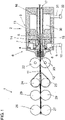
- FIG 1 For a general understanding of the functioning of a spinning device 2, the basic structure of a drafting system 1 with a downstream spinning device 2, which is multi-part in this exemplary embodiment, is shown.
- the sliver 11 withdrawn from a sliver source, not shown here, is drawn in by an input roller pair formed by an input upper roller 26 and an input lower roller 27 .
- the sliver 11 is then drawn between the second upper drafting roller 28 and the second lower drafting roller 29 and the third upper drafting roller 24 and third lower drafting roller 25 and the subsequent output roller pair consisting of upper roller 22 and lower roller 23 warped.
- the drawn fiber sliver 11 then enters the spinning device 2 via an entry area 12 of a nozzle device 6 and is transformed there into a thread 16 using a thread-forming unit 3 and the nozzle device 6 of the spinning device 2 .
- the component of the spinning device 2 that has the entry area 12 forms, together with the nozzle device 6, a first part of the spinning device 2.
- the thread-forming unit 3 forms the second part of the spinning device 2, with the first and second parts facing each other for opening the spinning device 2 for cleaning and maintenance purposes are movably designed and stored.
- the nozzle device 6 has nozzles 7 , 8 which are connected to a compressed air source 10 via lines 9 .
- the air flowing out of the nozzles 7, 8 generates a rotating flow within a vortex chamber 4, with which the drawn sliver 11 being supplied is acted upon.
- the thread-forming unit 3 has a thread-forming element designed as a spinning cone 5 which, in cooperation with the nozzle device 6 , forms the thread 16 which is drawn off from the spinning device 2 via the hollow spinning cone 5 via an outlet opening 17 .
- An expansion space 30 that follows the whirl chamber 4 in the thread withdrawal direction is coupled via a further line 31 to a vacuum air source 32 for removing fiber residues.
- the outer winding fibers 19 are wound around the inner core fibers 18 of the sliver 11 due to the turbulent air flow generated within the spinning device 2 or turbulence chamber 4, thereby ensuring the desired strength of the thread 16.
- FIG 2 An embodiment of a spinning device 2 according to a preferred embodiment is shown in the region of the spinning cone 5 and the shell wall 14 of a spinning housing 13 coaxially surrounding the spinning cone 5 .
- the core fiber 18 of the drawn sliver 11 enters a central opening of the hollow spinning cone 5, whereas the outer winding fibers 19 of the sliver 11 reach the enveloping gap 15 due to the air flow circulating around the spinning cone 5 in the region of the enveloping gap 15 between the enveloping wall 14 and the spinning cone 5 .
- opposite electrodes 20 are arranged on the spinning cone 5 and the enveloping wall 14 with the enveloping gap 15 in between, which together form a capacitor unit 21 .
- the electrodes 20 are insulated from the spinning cone 5 or the spinning housing 13, so that after an electric field has been built up between the electrodes 20, the capacitor unit 21 formed from the electrodes 20 experiences a change in capacitance, e.g Enveloping gap 15 learns.
- the electrodes 20 extend opposite one another over the entire peripheral surface of the spinning cone 5 or the casing wall 14 and thus form a capacitor unit 21 in the manner of a ring capacitor.
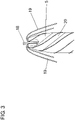
- the electrodes 20 extend only over a partial area in a spiral shape over the spinning cone 5 and in a corresponding manner on the opposite, not shown here, casing wall 14 of the spinning housing 13.
- the spiral alignment of the electrode 20 corresponds to the alignment of the winding fibers in the spinning operation due to the generated Air flow within the enveloping gap 15.
- This orientation of the electrode 20 thus enables good detection of the winding fibers 19 in the area between the electrodes 20, while at the same time conclusions can be drawn about the rotational speed of the winding fibers 19 around the Spinning cone 5 and measures that can be derived therefrom, such as an adjustment of the spinning process, an adjustment of a delay in the drafting system 1 and/or a stopping of the spinning process and, if necessary, a cleaning of the To tolerance deviations are possible before adjustment of the spinning process or the delay of the thread section produced from the thread.
Landscapes
- Engineering & Computer Science (AREA)
- Mechanical Engineering (AREA)
- Textile Engineering (AREA)
- Physics & Mathematics (AREA)
- General Physics & Mathematics (AREA)
- Spinning Or Twisting Of Yarns (AREA)
Abstract
Die Erfindung betrifft eine Spinnstelle einer Luftspinnmaschine mit einer Spinnvorrichtung sowie eine Spinnvorrichtung zur Herstellung eines Fadens aus einem zugeführten Faserband mittels eines umlaufenden Luftstroms, mit einem in einem Spinngehäuse angeordneten hohlen Spinnkonus, wobei das Spinngehäuse eine koaxial und im Abstand zum Spinnkonus angeordnete, einen Hüllspalt bildende Hüllwand aufweist und einer mit Druckluft beaufschlabaren Düsenvorrichtung zur Erzeugung eines den Spinnkonus im Hüllspalt umlaufenden Luftstroms. Ferner betrifft die Erfindung ein Verfahren zur Überwachung des Spinnvorgangs an einer Spinnvorrichtung. Um eine Spinnstelle einer Luftspinnmaschine mit einer Spinnvorrichtung bereitzustellen, welche die Fadenqualität mindernde Prozessstörungen bereits während des Spinnprozesses erfasst und um ein Verfahren zur Überwachung des Spinnprozesses an der Spinnvorrichtung bereitzustellen, ist vorgesehen, dass bei der Spinnvorrichtung der Spinnkonus und die Hüllwand zur Bildung einer Kondensatoreinheit einander unter Zwischenlage des Hüllspaltes gegenüberliegend angeordnete, ein Elektrodenpaar bildende Elektroden aufweisen.The invention relates to a spinning position of an air-jet spinning machine with a spinning device and a spinning device for producing a thread from a supplied fiber sliver by means of a circulating air stream, with a hollow spinning cone arranged in a spinning housing, the spinning housing forming an enveloping gap arranged coaxially and at a distance from the spinning cone Has casing wall and a nozzle device which can be acted upon with compressed air for generating an air flow circulating around the spinning cone in the casing gap. The invention also relates to a method for monitoring the spinning process on a spinning device. In order to provide a spinning position of an air-jet spinning machine with a spinning device, which already detects process disruptions that reduce the thread quality during the spinning process and to provide a method for monitoring the spinning process on the spinning device, it is provided that the spinning cone and the shell wall of the spinning device are connected to one another to form a condenser unit have electrodes arranged opposite one another with the interposition of the enveloping gap and forming a pair of electrodes.
Description
Die Erfindung betrifft eine Spinnstelle einer Luftspinnmaschine mit einer Spinnvorrichtung sowie eine Spinnvorrichtung zur Herstellung eines Fadens aus einem zugeführten Faserband mittels eines umlaufenden Luftstroms, mit
- einem in einem Spinngehäuse angeordneten hohlen Spinnkonus, wobei das Spinngehäuse eine koaxial und im Abstand zum Spinnkonus angeordnete, einen Hüllspalt bildende Hüllwand aufweist und
- einer mit Druckluft beaufschlabaren Düsenvorrichtung zur Erzeugung eines den Spinnkonus im Hüllspalt umlaufenden Luftstroms.
- a hollow spinning cone disposed in a spinning case, the spinning case having a shell wall coaxial with and spaced from the spinning cone and forming a shroud gap; and
- a nozzle device that can be pressurized with compressed air to generate an air flow circulating around the spinning cone in the enveloping gap.
Spinnvorrichtungen, Spinnvorrichtungen aufweisende Spinnstellen sowie aus einer Mehrzahl nebeneinander angeordneter Spinnstellen gebildete Luftspinnmaschinen sind in vielfältigen Ausgestaltungen aus dem Stand der Technik bekannt.Spinning devices, spinning positions having spinning devices, and air-jet spinning machines formed from a plurality of spinning positions arranged next to one another are known in a variety of configurations from the prior art.
Den Spinnvorrichtungen der eingangs genannten Art, wie sie bspw. aus der
Infolge von Prozessstörungen während des Spinnvorgangs, bspw. hervorgerufen durch Verstopfungen oder Verschmutzungen der Düsen oder des Hüllspalts, kann das Problem sogenannter drehungsfreier Stellen bzw. Stellen mit geringer Umwindefaserzahl und/oder geringer Drehung im Faden auftreten. Diese Stellen bilden Schwachstellen im Faden, welche zu Fadenbrüchen bei der Weiterverarbeitung führen können. Über einen längeren Zeitraum bestehende Prozessstörungen können dabei überdies zur Folge haben, dass vollständig mit fehlerbehafteten Fäden versehene Spulen hergestellt werden, die nicht zur Weiterverarbeitung geeignet sind.As a result of process disruptions during the spinning process, for example caused by blockages or contamination of the nozzles or the enveloping gap, the problem of so-called twist-free points or points with a low number of twisted fibers and/or low twist in the thread can occur. These points form weak points in the thread, which contribute to thread breaks can lead to further processing. Process disturbances that have existed for a longer period of time can moreover have the result that bobbins are produced that are completely provided with faulty threads that are not suitable for further processing.
Um solche Problemstellen im Faden sicher auszuschließen, ist es erforderlich, im Falle von Prozessstörungen, die Fehlstellen an den Fäden zur Folge haben, den Spinnprozess zu unterbrechen. Voraussetzung hierfür ist eine zuverlässige Detektion von Prozessstörungen, was derzeit nur indirekt über eine Überwachung des aus der Spinnvorrichtung austretenden Fadens erfolgen kann, wobei bspw. Haarigkeitsunterschiede bzw. Durchmesserunterschiede Indizien für Prozessstörungen während des Spinnprozesses darstellen können. Eine derartige Erfassung von Prozessstörungen weist jedoch den Nachteil auf, dass diese nur eine bedingte Zuverlässigkeit besitzen und überdies bereits zu einem fehlerbehafteten Faden geführt haben können.In order to reliably rule out such problem areas in the thread, it is necessary to interrupt the spinning process in the event of process disruptions that result in defects in the threads. A prerequisite for this is a reliable detection of process disturbances, which can currently only be done indirectly by monitoring the thread exiting the spinning device, whereby, for example, differences in hairiness or diameter differences can represent indications of process disturbances during the spinning process. However, detecting process disturbances in this way has the disadvantage that they only have a limited reliability and, moreover, may already have led to a faulty thread.
Hiervon ausgehend liegt der Erfindung die Aufgabe zugrunde, eine Spinnstelle einer Luftspinnmaschine mit einer Spinnvorrichtung sowie eine solche Spinnvorrichtung bereitzustellen, welche die Fadenqualität mindernde Prozessstörungen bereits während des Spinnprozesses, also ursächlich erfassen kann. Ferner liegt der Erfindung die Aufgabe zugrunde, ein Verfahren zur Überwachung des Spinnprozesses bereitzustellen.Proceeding from this, the object of the invention is to provide a spinning station of an air-jet spinning machine with a spinning device and such a spinning device which can already detect process disruptions that reduce the thread quality during the spinning process, ie, cause them. Furthermore, the object of the invention is to provide a method for monitoring the spinning process.
Die Erfindung löst die Aufgabe durch eine Spinnvorrichtung mit den Merkmalen des Anspruchs 1, eine Spinnstelle einer Luftspinnmaschine mit den Merkmalen des Anspruchs 6 sowie durch ein Verfahren mit den Merkmalen des Anspruchs 7. Vorteilhafte Weiterbildungen der Spinnvorrichtung sind in den abhängigen Ansprüchen 2 bis 5 dargestellt.The invention solves the problem by a spinning device with the features of claim 1, a spinning position of an air-jet spinning machine with the features of
Kennzeichnend für die erfindungsgemäße Spinnvorrichtung ist, dass der Spinnkonus und die Hüllwand zur Bildung einer Kondensatoreinheit einander unter Zwischenlage des Hüllspaltes gegenüberliegend angeordnete, ein Elektrodenpaar bildende Elektroden aufweisen.It is characteristic of the spinning device according to the invention that the spinning cone and the shell wall have electrodes arranged opposite one another, forming a pair of electrodes, to form a capacitor unit with the shell gap being interposed.
Gemäß der Erfindung ist vorgesehen, dass der Spinnkonus und die Hüllwand, bzw. Abschnitte von Spinnkonus und Hüllwand, jeweils eine Elektrode einer Kondensatoreinheit aufweisen, insbesondere bilden. Die Kapazität der Kondensatoreinheit, bzw. des gebildeten Kondensators hängt dabei neben den geometrischen Abmessungen der Elektroden sowie dem Abstand der Elektroden voneinander von dem zwischen den beiden Elektroden angeordneten Material ab. Gegenüber der Kapazität der Kondensatoreinheit im fadenfreien Zustand, d. h., wenn der den Zwischenraum ausfüllende Hüllspalt zwischen den Elektroden allein durch die Umgebungsluft ausgefüllt ist, bewirken in dem Hüllspalt angeordnete Umwindefasern während eines Spinnbetriebs eine messbare Veränderung der Kapazität der Kondensatoreinheit. Die Veränderung der Kapazität der Kondensatoreinheit kann abhängig von der Auslegung der Kondensatoreinheit eine messbare Erhöhung oder Reduzierung sein.According to the invention, it is provided that the spinning cone and the shell wall, or sections of the spinning cone and shell wall, each have, in particular form, an electrode of a capacitor unit. The capacitance of the capacitor unit, or of the capacitor formed, depends not only on the geometric dimensions of the electrodes and the spacing of the electrodes from one another, but also on the material arranged between the two electrodes. Compared to the capacitance of the capacitor unit in the filament-free state, ie when the den Since the enveloping gap between the electrodes that fills the gap is filled solely by the ambient air, winding fibers arranged in the enveloping gap bring about a measurable change in the capacitance of the capacitor unit during spinning operation. The change in the capacitance of the capacitor unit can be a measurable increase or decrease depending on the design of the capacitor unit.
Über die Kondensatoreinheit lässt sich somit die Masse der im Hüllspalt zwischen den Elektroden angeordneten Umwindefasern kontinuierlich erfassen. Nimmt die Masse der Umwindefasern im Bereich zwischen den Elektroden ab, dann reduziert sich vorzugsweise die Kapazität der Kondensatoreinheit. Ein Absinken der Kapazität der Kondensatoreinheit unter einen für einen ordnungsgemäßen Faden festgelegten unteren Grenzwert, signalisiert somit, dass die Masse der erforderlichen Umwindefasern unterschritten ist. Wird über eine mit der Kondensatoreinheit verbundene Auswerteinheit eine entsprechend bevorzugte Reduzierung der Kapazität unter den zuvor festgelegten Grenzwert festgestellt, dann können die entsprechenden Spinnstellen sofort abgestellt und geeignete Störungsbeseitigungsmaßnahmen durchgeführt werden. Auch ein Anstieg der Kapazität über einen oberen Grenzwert ist mittels einer an die Kondensatoreinheit angeschlossenen Auswerteinheit erfassbar. Übersteigt die Kapazität einen festgelegten oberen Grenzwert, ist dies bspw. ein Indiz für eine übermäßige Ansammlung von Fasern, die eine Rotation der Umwindefasern blockieren, sodass in der Folge der Spinnprozesses ebenfalls gestoppt werden kann.The mass of the winding fibers arranged in the enveloping gap between the electrodes can thus be continuously detected via the capacitor unit. If the mass of the winding fibers decreases in the area between the electrodes, then the capacitance of the capacitor unit is preferably reduced. A drop in the capacitance of the capacitor unit below a lower limit specified for a proper thread thus signals that the mass of the required wrapping fibers has fallen below. If an evaluation unit connected to the capacitor unit detects a correspondingly preferred reduction in the capacity below the previously specified limit value, then the corresponding spinning stations can be switched off immediately and suitable measures to eliminate the fault can be carried out. An increase in the capacitance above an upper limit value can also be detected using an evaluation unit connected to the capacitor unit. If the capacity exceeds a specified upper limit value, this is, for example, an indication of an excessive accumulation of fibers that block rotation of the wrapping fibers, so that the spinning process can also be stopped as a result.
Die erfindungsgemäße Spinnvorrichtung ermöglicht es somit, den laufenden Spinnprozess kontinuierlich zu überwachen, wobei Störungen des Spinnprozesses aufgrund von einer zu geringen Anzahl von Umwindefasern oder Blockierungen im Hüllspalt, welche zu einem minderwertigen Faden führen können, unmittelbar erkannt werden können. Die erfindungsgemäße Spinnvorrichtung verhindert somit bereits die Entstehung eines fehlerbehafteten Fadens und ermöglicht es daher, auf nachgelagerte Untersuchungen des Fadens zu verzichten. Insgesamt gewährleistet damit die erfindungsgemäße Spinnvorrichtung in besonderer Weise die fehlerfreie Herstellung eines Fadens mit den geforderten Eigenschaften.The spinning device according to the invention thus makes it possible to continuously monitor the ongoing spinning process, with disturbances in the spinning process due to an insufficient number of wrapped fibers or blockages in the sheath gap, which can lead to an inferior thread, being immediately recognizable. The spinning device according to the invention thus already prevents the formation of a faulty thread and therefore makes it possible to dispense with subsequent examinations of the thread. Overall, the spinning device according to the invention thus ensures in a special way the error-free production of a thread with the required properties.
Die Ausbildung der Elektroden an oder mit der Hüllwand bzw. dem Spinnkonus kann grundsätzlich in beliebiger Weise erfolgen. So besteht bspw. die Möglichkeit, die Elektroden einstückig mit der Hüllwand und/oder dem Spinnkonus auszubilden, wobei hierzu Abschnitte der Hüllwand und/oder des Spinnkonus als Elektroden fungieren, welche jedoch zur Bildung einer Kondensatoreinheit gegenüber den übrigen Bauteilen isoliert sein müssen. Nach einer besonders vorteilhaften Ausgestaltung der Erfindung ist jedoch vorgesehen, dass die Elektroden einander unter Zwischenlage des Hüllspaltes gegenüberliegend an der Hüllwand und/oder dem Spinnkonus angebracht sind.In principle, the electrodes can be formed on or with the shell wall or the spinning cone in any desired manner. For example, there is the possibility of forming the electrodes in one piece with the shell wall and/or the spinning cone, with sections of the shell wall and/or the spinning cone act as electrodes, which, however, must be insulated from the other components in order to form a capacitor unit. According to a particularly advantageous embodiment of the invention, however, it is provided that the electrodes are fitted opposite one another on the casing wall and/or the spinning cone with the casing gap being interposed.
Gemäß dieser Ausgestaltung der Erfindung ist vorgesehen, dass separate Elektroden elektrisch nichtleitend mit der Hüllwand und/oder dem Spinnkonus verbunden sind. Die Anordnung der Elektroden kann dabei in beliebiger Weise, bspw. durch eine Klebeverbindung und/oder Schraubverbindung hergestellt werden, welche es im Bedarfsfall ermöglichen, die Elektroden einfach auszutauschen. Die Verwendung separater Elektroden zur Anordnung an der Hüllwand und/oder dem Spinnkonus ermöglicht es ferner in besonders einfacher Weise, diese gegenüber der Hüllwand und/oder dem Spinnkonus zu isolieren, wodurch eine Kondensatoreinheit auf einfache Weise gebildet werden kann.According to this embodiment of the invention, it is provided that separate electrodes are electrically non-conductively connected to the shell wall and/or the spinning cone. The electrodes can be arranged in any way, for example by means of an adhesive connection and/or screw connection, which makes it possible to easily replace the electrodes if necessary. The use of separate electrodes for arrangement on the shell wall and/or the spinning cone also makes it possible in a particularly simple manner to insulate them from the shell wall and/or the spinning cone, as a result of which a capacitor unit can be formed in a simple manner.
Die Ausgestaltung der Kondensatoreinheit, d. h. unter anderem die Ausdehnung der Elektroden an der Hüllwand und dem Spinnkonus, ist grundsätzlich frei wählbar. So besteht bspw. die Möglichkeit, die Elektroden derart auszubilden, dass diese sich über den gesamten Umfang der Hüllwand und des Spinnkonus erstrecken, sodass dann eine Kondensatoreinheit nach Art eines Ringkondensators gebildet wird, wodurch in besonders zuverlässiger Weise der Füllzustand des Hüllspalts erfasst werden kann.The design of the capacitor unit, i. H. among other things, the extension of the electrodes on the shell wall and the spinning cone can be freely selected. For example, there is the possibility of designing the electrodes in such a way that they extend over the entire circumference of the shell wall and the spinning cone, so that a capacitor unit is then formed in the manner of a ring capacitor, as a result of which the fill level of the shell gap can be detected in a particularly reliable manner.
Nach einer besonders bevorzugten Ausgestaltung der Erfindung ist vorgesehen, dass sich zwei oder mehrere Elektrodenpaare über einen in Umfangsrichtung von Hüllwand und Spinnkonus abgegrenzten Bereich erstrecken. Gemäß dieser Ausgestaltung der Erfindung erstrecken sich die Elektroden nur über einen abgegrenzten Abschnitt in Umfangrichtung des Hüllspalts. In Umfangsrichtung des Hüllspalts sind somit ein oder mehrere nicht durch eine Kondensatoreinheit eingeschlossene Abschnitte des Hüllspalts benachbart zu durch eine Kondensatoreinheit eingeschlossene Abschnitte angeordnet. Dabei können sich die Elektroden in bevorzugter Weise mit Ihrer Längsachse in Umfangsrichtung, schräg dazu oder orthogonal in Umfangsrichtung und/oder in Umfangsrichtung definiert verteilt erstrecken bzw. angeordnet sein. Die Längsachse der Elektrode entspricht derjenigen Erstreckung der Elektrode, welche vom Betrag größer als die dazu orthogonal verlaufende Erstreckung, welche als Breite der Elektrode verstanden wird, ist.According to a particularly preferred embodiment of the invention, it is provided that two or more pairs of electrodes extend over an area delimited in the circumferential direction by the casing wall and the spinning cone. According to this embodiment of the invention, the electrodes only extend over a delimited section in the circumferential direction of the enveloping gap. In the circumferential direction of the enclosing gap, one or more sections of the enclosing gap not enclosed by a capacitor unit are thus arranged adjacent to sections enclosed by a capacitor unit. The electrodes can preferably extend or be arranged with their longitudinal axis in the circumferential direction, obliquely thereto or orthogonally in the circumferential direction and/or in the circumferential direction. The longitudinal axis of the electrode corresponds to that extension of the electrode which is greater in magnitude than the extension running orthogonally thereto, which is understood as the width of the electrode.
Diese bevorzugte Ausgestaltung der Erfindung ermöglicht neben oder alternativ zu einer Erfassung des Füllzustandes des Hüllspalts, also einer Anzahl der Umwindefasern bzw. der Faserdichte im Hüllspalt, auch eine Detektion der Rotationsgeschwindigkeit der Umwindefasern um den Spinnkonus im Hüllspalt, nachdem die Umwindefasern aufgrund ihrer Rotation um den Spinnkonus durch mittels einer Kondensatoreinheit überwachte sowie nicht überwachte Bereiche hindurchrotieren. Die Frequenz der dabei auftretenden Kapazitätsänderungen einer oder mehrerer Kondensatoreinheiten ermöglicht einen Rückschluss auf die Rotationsgeschwindigkeit der Umwindefasern um den Spinnkonus.In addition to or as an alternative to detecting the filling level of the enveloping gap, i.e. a number of the wrapped fibers or the fiber density in the enveloping gap, this preferred embodiment of the invention also enables the rotational speed of the wrapped fibers around the spinning cone in the enveloping gap to be detected after the wrapped fibers due to their rotation around the Rotate the spinning cone through areas monitored and unmonitored by a condenser unit. The frequency of the changes in capacitance occurring in one or more capacitor units enables conclusions to be drawn about the rotational speed of the winding fibers around the spinning cone.
In besonders vorteilhafter Weise ist vorgesehen, dass die Elektroden spiralförmig an der Hüllwand und dem Spinnkonus angeordnet sind. Gemäß dieser Ausgestaltung der Erfindung erstrecken sich die Elektroden in bevorzugter Weise unter Berücksichtigung toleranzbedingter Abweichungen korrespondierend zu der Längsrichtung der Umwindefasern im Hüllspalt während des Spinnbetriebs, welche sich während des Spinnbetriebs spiralförmig um den Spinnkonus wickeln. Die der spiralförmigen Wicklung der Umwindefasern während des Spinnbetriebs entsprechende spiralförmige bzw. schraubenförmige Anbringung der Elektroden an der Hüllwand und dem Spinnkonus entspricht folglich der Ausrichtung der Umwindefasern, sodass diese bei ihrer Rotation um den Spinnkonus mit einem längeren Abschnitt durch die Kondensatoreinheiten hindurchgeführt werden, was dann zu höheren Kapazitätsänderungen führt, welche eine Signalverarbeitung vereinfachen.In a particularly advantageous manner, it is provided that the electrodes are arranged in a spiral shape on the shell wall and the spinning cone. According to this embodiment of the invention, the electrodes extend in a preferred manner, taking into account tolerance-related deviations, corresponding to the longitudinal direction of the winding fibers in the enveloping gap during spinning, which spirally wind around the spinning cone during spinning. The spiral or helical attachment of the electrodes to the shell wall and the spinning cone, corresponding to the spiral winding of the wrapping fibers during the spinning operation, consequently corresponds to the orientation of the wrapping fibers, so that during their rotation around the spinning cone they are passed through the capacitor units with a longer section, which then leads to higher changes in capacitance, which simplify signal processing.
Nach einer weiteren Ausgestaltung der Erfindung ist ferner vorgesehen, dass dem Hüllspalt zugewandte Oberflächen der Elektroden wenigstens einer Kondensatoreinheit ein elektrisch nicht leitfähiges Material aufweisen. Eine entsprechende Ausgestaltung der Oberflächen dieser Elektroden kann grundsätzlich in beliebiger Weise erfolgen, bspw. durch die Aufbringung einer Beschichtung oder einer sonstigen, die leitfähige Oberfläche überdeckenden Abdeckung. Eine entsprechende Ausgestaltung verhindert in besonders zuverlässiger Weise Störungen bei der Erfassung der Kapazitätsänderungen, welche bspw. aus einer statischen Aufladung durch die bewegten Fasern resultieren.According to a further embodiment of the invention, it is further provided that surfaces of the electrodes of at least one capacitor unit facing the enveloping gap have an electrically non-conductive material. A corresponding configuration of the surfaces of these electrodes can in principle take place in any manner, for example by applying a coating or some other covering covering the conductive surface. A corresponding configuration prevents disturbances in the detection of the changes in capacitance, which result, for example, from static charging caused by the moving fibers, in a particularly reliable manner.
Die Erfindung löst die Aufgabe ferner durch eine Spinnstelle einer Luftspinnmaschine zum Herstellen eines Fadens aus einem zugeführten Faserband, mit einer Spinnvorrichtung zur Bildung des Fadens aus wenigstens einem über ein Streckwerk zugeführten Faserband, und einer Aufspuleinrichtung zum Aufspulen des Fadens auf eine Auflaufspule, wobei die Spinnvorrichtung in der vorbeschriebenen erfindungsgemäßen oder weitergebildeten Weise ausgebildet ist.The invention also achieves the object by means of a spinning station of an air-jet spinning machine for producing a thread from a supplied sliver, with a spinning device for forming the thread from at least one sliver fed via a drafting system, and a winding device for winding the thread onto a take-up spool, the spinning device in is formed in the manner described above according to the invention or developed further.
Die erfindungsgemäße Spinnstelle zeichnet sich dabei dadurch aus, dass aufgrund der Verwendung einer erfindungsgemäßen oder weitergebildeten Spinnvorrichtung an der Spinnmaschine Störungen des Spinnprozesses unmittelbar erkannt und der Spinnvorgang unterbrochen werden kann, sodass dann Störungsbeseitigungsmaßnahmen eingeleitet werden können. Durch die kontinuierliche Überwachung des Spinnprozesses kann die Entstehung eines Fadens mit von festgelegten Eigenschaften abweichenden Eigenschaften bereits vermieden werden, sodass darüber hinaus an der Luftspinnmaschine auf weitere Einrichtungen zur Überprüfung der Fadenqualität verzichtet werden kann.The spinning position according to the invention is characterized in that due to the use of a spinning device according to the invention or a further development on the spinning machine, disruptions in the spinning process can be recognized immediately and the spinning process can be interrupted so that fault elimination measures can then be initiated. The continuous monitoring of the spinning process can already prevent the formation of a thread with properties that deviate from the specified properties, so that further devices for checking the thread quality can be dispensed with on the air-jet spinning machine.
Die Erfindung löst die Aufgabe ferner durch ein Verfahren zur Überwachung des Spinnvorgangs an einer vorbeschriebenen erfindungsgemäßen oder weitergebildeten Spinnvorrichtung, wobei zur Erfassung wenigstens einer Charakteristik der Umwindefasern, insbesondere der Anzahl an Umwindefasern bzw. der Faserdichte, im Hüllspalt die Schritte:
- Aufbauen eines elektrischen Feldes im Bereich zwischen den Elektroden,
- Erfassung der Kapazität der Kondensatoreinheit im fadenfreien Zustand,
- Erfassung der Kapazitätsänderung im Spinnbetrieb,
- Überwachung und Abgleich der Kapazitätsänderung mit für einen ordnungsgemäßen Faden bekannten oder zuvor ermittelten Referenzwerten,
- building up an electric field in the area between the electrodes,
- detection of the capacity of the capacitor unit in the filament-free state,
- Detection of the change in capacity in the spinning operation,
- Monitoring and comparison of the change in capacitance with known or previously determined reference values for a correct thread,
Gemäß dem erfindungsgemäßen Verfahren ist vorgesehen, dass nach dem Aufbauen eines elektrischen Feldes an einer oder mehrerer Kondensatoreinheiten und der Erfassung deren Kapazität im fadenfreien Zustand, die im Spinnbetrieb aus der Anordnung der Umwindefasern im Bereich zwischen den Elektroden resultierende Kapazitätsänderung erfasst und kontinuierlich mit einem bekannten oder ermittelten, vorzugsweise bereits hinterlegten oder übermittelten, Referenzwert oder Referenzwertbereich zur Kapazitätsänderung im Spinnvorgang abgeglichen wird, wobei der Referenzwert bzw. der Referenzwertbereich zuvor für einen solchen Spinnvorgang ermittelt wurde, in denen ein Faden in ordnungsgemäßer Weise hergestellt wurde.According to the method according to the invention, it is provided that after an electric field has been built up on one or more capacitor units and their capacitance has been recorded in the filament-free state, the change in capacitance resulting from the arrangement of the winding fibers in the area between the electrodes during spinning is recorded and continuously measured with a known or determined, preferably already stored or transmitted, reference value or reference value range for the change in capacity in the spinning process is compared, the reference value or the reference value range having been previously determined for such a spinning process in which a thread was produced in a proper manner.
Abweichungen der Kapazitätsänderungen von dem Referenzwert bzw. dem Referenzwertbereich signalisieren Störungen im Spinnprozess, wobei beispielsweise eine über einen Grenzwert hinausgehende bzw. einen Grenzwertbereich überschreitende Kapazitätserhöhung auf eine übermäßige Anordnung von Fäden oder Fadenresten im Bereich zwischen den Elektroden hindeutet. Eine Unterschreitung eines unteren Grenzwerts der Kapazitätsänderung deutet vorzugsweise hingegen darauf hin, dass zu wenig Umwindefasern im Hüllspalt angeordnet sind, was bei dem Spinnprozess zu Schwachstellen des hergestellten Fadens führen kann.Deviations in the changes in capacitance from the reference value or the reference value range signal disruptions in the spinning process, with a value exceeding a limit value, for example or an increase in capacitance that exceeds a limit value indicates an excessive arrangement of threads or thread residues in the area between the electrodes. On the other hand, if the change in capacitance falls below a lower limit value, this indicates that too few winding fibers are arranged in the enveloping gap, which can lead to weak points in the yarn produced during the spinning process.
In bevorzugter Weise erfolgt das Verfahren zur Überwachung des Spinnvorgangs an einer vorbeschriebenen weitergebildeten Spinnvorrichtung umfassend die spiralförmige Anordnung der Elektroden, indem mit den Schritten eine Erfassung von Kapazitätsänderungen und ihrer Frequenz im Spinnbetrieb und eine Überwachung und ein Abgleich der Frequenz der Kapazitätsänderungen mit einem für einen ordnungsgemäßen Faden bekannten oder zuvor ermittelten Referenzwert und/oder Referenzwertbereich erfolgt. Dadurch können die erfindungsgemäßen Schritte nicht nur zur Erfassung der Charakteristik der Faserdichte, sondern zusätzlich oder alternativ zur Erfassung der Charakteristik der Rotationsgeschwindigkeit der die Faserdichte ausmachenden Umwindefasern im Hüllspalt hergenommen werden.The method for monitoring the spinning process is preferably carried out on a spinning device that has been developed as described above, comprising the spiral arrangement of the electrodes, by using the steps of detecting changes in capacitance and their frequency in the spinning operation and monitoring and comparing the frequency of the changes in capacitance with a for a proper Thread known or previously determined reference value and / or reference value range takes place. As a result, the steps according to the invention can be used not only for detecting the characteristic of the fiber density, but also additionally or alternatively for detecting the characteristic of the rotational speed of the wrapping fibers in the enveloping gap that make up the fiber density.
Störungen im Spinnprozess können somit zusätzlich oder alternativ durch Erfassung einer Abweichung der Frequenz auftretender Kapazitätsänderungen von einem korrespondierenden Referenzwert oder Referenzwertbereich erfasst werden, welche auf eine zu niedrige oder zu hohe Rotationsgeschwindigkeit hinweisen.Disturbances in the spinning process can thus additionally or alternatively be detected by detecting a deviation in the frequency of occurring changes in capacitance from a corresponding reference value or range of reference values, which indicate a rotational speed that is too low or too high.
So kann nach einer weiteren bevorzugten Ausführungsform im Falle einer Abweichung der Frequenz von einem vorbestimmten Referenzwert oder einem Referenzwertbereich der Spinnvorgang angepasst oder gestoppt werden, um im Falle eines außerhalb der Toleranz liegenden Wertes Schwachstellen im Faden zu vermeiden. Zur Anpassung des Spinnvorgangs kann beispielsweise wenigstens eine den Spinnvorgang ausmachende Charakteristik wie ein eine Wirbelkammer der Spinnvorrichtung beaufschlagender Druck, eine Faserbandzuführgeschwindigkeit und/oder eine Fadenabzugsgeschwindigkeit angepasst werden. Ein die Wirbelkammer beaufschlagender Druck kann dabei ein zur Erzeugung einer Wirbelluftströmung in der Wirbelkammer der Spinnvorrichtung anliegender Überdruck und/oder ein die Wirbelkammer beaufschlagener Unterdruck sein, welcher insbesondere zur Unterstützung der Abführung von Fasern, die im Spinnbetrieb nicht in den Faden eingebunden werden, aus der Spinnvorrichtung dient.According to a further preferred embodiment, if the frequency deviates from a predetermined reference value or a reference value range, the spinning process can be adjusted or stopped in order to avoid weak points in the thread if the value is outside the tolerance. To adapt the spinning process, at least one characteristic that makes up the spinning process, such as a pressure acting on a turbulence chamber of the spinning device, a sliver feed speed and/or a thread withdrawal speed, can be adjusted. A pressure applied to the turbulence chamber can be an overpressure applied to generate a turbulence air flow in the turbulence chamber of the spinning device and/or a negative pressure applied to the turbulence chamber, which is used in particular to support the removal of fibers that are not tied into the thread during spinning, from the Spinning device is used.
Alternativ oder zusätzlich kann nach einer weiteren bevorzugten Ausführungsform ein Verzug des Faserbandes in einer der Spinnvorrichtung vorgeschalteten Streckwerkvorrichtung angepasst werden, mittels welchem die Fadencharakteristik im Zuge des Spinnvorgangs ebenfalls geeignet beeinflussbar ist.Alternatively or additionally, according to a further preferred embodiment, a delay of the fiber sliver can be adjusted in a drafting system device connected upstream of the spinning device, by means of which the thread characteristics can likewise be suitably influenced in the course of the spinning process.
Besonders bevorzugt erfolgt im Zuge der Anpassung des Spinnvorgangs und/oder des Verzugs oder diesen nachgängig eine Ausreinigung des während der erfassten Toleranzabweichung vor Anpassung des Spinnvorgangs bzw. des Verzugs hergestellten Fadenabschnitts aus dem Faden.Particularly preferably, in the course of the adjustment of the spinning process and/or the draft or after this, the thread section produced during the detected tolerance deviation before the adjustment of the spinning process or the draft is cleaned out of the thread.
Das vorgeschlagene Verfahren ermöglicht es somit, den Spinnprozess kontinuierlich zu überwachen und im Falle einer Störung, welche zu nicht tolerierbaren Qualitätsänderungen des Fadens führen würde, den Spinnprozess unmittelbar anzupassen oder zu unterbrechen, sodass die Herstellung eines fehlerbehafteten Fadens bzw. die Herstellung einer einen fehlerbehafteten Faden aufweisenden Auflaufspule vermieden werden kann.The proposed method thus makes it possible to continuously monitor the spinning process and, in the event of a fault that would lead to intolerable changes in the quality of the thread, to immediately adjust or interrupt the spinning process, so that the production of a defective thread or the production of a defective thread having package can be avoided.
Ein Ausführungsbeispiel der Erfindung wird nachstehend mit Bezug auf die Zeichnungen erläutert. In den Zeichnungen zeigen:
- Fig. 1
- eine schematische Darstellung einer aus dem Stand der Technik bekannten Spinnvorrichtung mit vorgelagertem Streckwerk;
- Fig. 2
- in einer Schnittansicht eine schematische Darstellung einer Spinnvorrichtung nach einem bevorzugten Ausführungsbeispiel im Bereich eines Hüllspalts zwischen einer Hüllwand und einem Spinnkonus;
- Fig. 3
- eine schematische Darstellung des Spinnkonus der Spinnvorrichtung von
Fig. 2 im Spinnbetrieb.
- 1
- a schematic representation of a known from the prior art spinning device with upstream drafting system;
- 2
- in a sectional view, a schematic representation of a spinning device according to a preferred embodiment in the region of a casing gap between a casing wall and a spinning cone;
- 3
- a schematic representation of the spinning cone of the spinning device of
2 in the spinning mill.
In
Die Düsenvorrichtung 6 weist Düsen 7, 8 auf, welche über Leitungen 9 mit einer Druckluftquelle 10 verbunden sind. Die aus den Düsen 7, 8 ausströmende Luft erzeugt innerhalb einer Wirbelkammer 4 eine Rotationsströmung, mit der das zugeführte verstreckte Faserband 11 beaufschlagt wird. Die Fadenbildungseinheit 3 weist ein als Spinnkonus 5 ausgebildetes Fadenbildungselement auf, welches im Zusammenwirken mit der Düsenvorrichtung 6 den Faden 16 bildet, der über den hohlen Spinnkonus 5 über eine Austrittsöffnung 17 aus der Spinnvorrichtung 2 abgezogen wird. Ein der Wirbelkammer 4 in Fadenabzugsrichtung folgender Expansionsraum 30 ist über eine weitere Leitung 31 mit einer Unterdruckluftquelle 32 zum Abführen von Faserresten gekoppelt.The
In der Spinnvorrichtung 2 werden die äußeren Umwindefasern 19 aufgrund der innerhalb der Spinnvorrichtung 2 bzw. Wirbelkammer 4 erzeugten Wirbelluftströmung um die innenliegenden Kernfasern 18 des Faserbands 11 gewunden und gewährleisten hierdurch die gewünschte Festigkeit des Fadens 16.In the
In
Zur Erfassung der Faserdichte im Hüllspalt 15 sind an dem Spinnkonus 5 und der Hüllwand 14 einander unter Zwischenlage des Hüllspalts 15 gegenüberliegende Elektroden 20 angeordnet, die gemeinsam eine Kondensatoreinheit 21 bilden. Die Elektroden 20 sind gegenüber dem Spinnkonus 5 bzw. dem Spinngehäuse 13 isoliert, sodass nach dem Aufbauen eines elektrischen Feldes zwischen den Elektroden 20 die aus den Elektroden 20 gebildete Kondensatoreinheit 21 beim Durchlaufen der Umwindefasern 19 eine Kapazitätsänderung, bspw. eine Kapazitätserhöhung, gegenüber einem faserfreien Hüllspalt 15 erfährt.To detect the fiber density in the
Mittels Überwachung und Abgleich der Kapazitätsänderung mit für einen ordnungsgemäßen Faden gekannten oder ermittelten Referenzwert, welcher abrufbar hinterlegt oder übermittelbar sein kann, lassen sich somit Rückschlüsse über den Füllzustand des Hüllspalts 15, insbesondere auf eine Anzahl der Umwindefasern 19 bzw. die Faserdichte, ziehen, wobei insbesondere eine übermäßige Kapazitätserhöhung auf eine Verschmutzung des Hüllspalts 15 und eine Verringerung der Kapazität gegenüber einem Referenzwert auf eine zu geringe Anordnung von Umwindefasern 19 im Hüllspalt 15 hinweisen kann.By monitoring and comparing the change in capacitance with a known or determined reference value for a correct thread, which can be stored or transmitted so that it can be called up, conclusions can be drawn about the fill level of the enveloping
Bei dem in
In dem in
- 11
- Streckwerkdrafting system
- 22
- Spinnvorrichtungspinning device
- 33
- Fadenbildungseinheitthread forming unit
- 44
- Wirbelkammervortex chamber
- 55
- Spinnkonusspinning cone
- 66
- Düsenvorrichtungnozzle device
- 77
- Düsejet
- 88th
- Düsejet
- 99
- LeitungManagement
- 1010
- Druckluftquellecompressed air source
- 1111
- Faserbandsliver
- 1212
- Eintrittsbereichentry area
- 1313
- Spinngehäusespin housing
- 1414
- Hüllwandshell wall
- 1515
- Hüllspaltenvelope gap
- 1616
- Fadenthread
- 1717
- Austrittsöffnungexit port
- 1818
- Kernfasercore fiber
- 1919
- Umwindefasernwrapping fibers
- 2020
- Elektrodeelectrode
- 2121
- Kondensatoreinheitcondenser unit
- 2222
- Ausgangsoberwalzeoutput top roller
- 2323
- Ausgangsunterwalzeexit bottom roller
- 2424
- dritte Streckwerkoberwalzethird drafting system top roller
- 2525
- dritte Streckwerkunterwalzethird drafting system bottom roller
- 2626
- Eingangsoberwalzeinput top roller
- 2727
- Eingangsunterwalzeinput bottom roller
- 2828
- zweite Streckwerkoberwalzesecond drafting system top roller
- 2929
- zweite Streckwerkunterwalzesecond drafting system bottom roller
- 3030
- Expansionsraumexpansion space
- 3131
- weitere Leitungfurther line
- 3232
- Unterdruckluftquellevacuum air source
Claims (9)
der Spinnkonus (5) und die Hüllwand (14) zur Bildung einer Kondensatoreinheit (21) einander unter Zwischenlage des Hüllspaltes (15) gegenüberliegend angeordnete, ein Elektrodenpaar bildende Elektroden (20) aufweisen.Spinning device for producing a thread (16) from a supplied fiber sliver by means of a circulating air stream
the spinning cone (5) and the shell wall (14) for forming a capacitor unit (21) have electrodes (20) arranged opposite one another with the shell gap (15) in between and forming a pair of electrodes.
einer Spinnvorrichtung (2) zur Bildung des Fadens (16) aus wenigstens einem über ein Streckwerk (1) zugeführten Faserband (11), und
einer Aufspuleinrichtung zum Aufspulen des Fadens (16) auf eine Auflaufspule, dadurch gekennzeichnet, dass
die Spinnvorrichtung (2) nach einem oder mehreren der Ansprüche 1 bis 5 ausgebildet ist.Spinning station of an air-jet spinning machine for producing a thread (16) from a supplied fiber sliver
a spinning device (2) for forming the thread (16) from at least one sliver (11) fed via a drafting system (1), and
a winding device for winding the thread (16) onto a winding bobbin, characterized in that
the spinning device (2) is designed according to one or more of claims 1 to 5.
Priority Applications (4)
| Application Number | Priority Date | Filing Date | Title |
|---|---|---|---|
| EP20215384.7A EP4015683B1 (en) | 2020-12-18 | 2020-12-18 | Method for monitoring the spinning process on a spinning device, spinning station of an air spinning machine and spinning device |
| JP2021205373A JP2022097470A (en) | 2020-12-18 | 2021-12-17 | Method for monitoring spinning process on spinning device, spinning unit of air spinning machine and spinning device |
| US17/554,380 US11926934B2 (en) | 2020-12-18 | 2021-12-17 | Method for monitoring the spinning process on a spinning device, spinning position of an air-spinning machine and spinning device |
| CN202111552095.4A CN114645348B (en) | 2020-12-18 | 2021-12-17 | Method for monitoring spinning process, spinning position of open-end spinning machine and spinning device |
Applications Claiming Priority (1)
| Application Number | Priority Date | Filing Date | Title |
|---|---|---|---|
| EP20215384.7A EP4015683B1 (en) | 2020-12-18 | 2020-12-18 | Method for monitoring the spinning process on a spinning device, spinning station of an air spinning machine and spinning device |
Publications (2)
| Publication Number | Publication Date |
|---|---|
| EP4015683A1 true EP4015683A1 (en) | 2022-06-22 |
| EP4015683B1 EP4015683B1 (en) | 2023-09-13 |
Family
ID=73855735
Family Applications (1)
| Application Number | Title | Priority Date | Filing Date |
|---|---|---|---|
| EP20215384.7A Active EP4015683B1 (en) | 2020-12-18 | 2020-12-18 | Method for monitoring the spinning process on a spinning device, spinning station of an air spinning machine and spinning device |
Country Status (4)
| Country | Link |
|---|---|
| US (1) | US11926934B2 (en) |
| EP (1) | EP4015683B1 (en) |
| JP (1) | JP2022097470A (en) |
| CN (1) | CN114645348B (en) |
Citations (3)
| Publication number | Priority date | Publication date | Assignee | Title |
|---|---|---|---|---|
| JPH076274U (en) * | 1993-06-29 | 1995-01-27 | 村田機械株式会社 | Pneumatic spinning equipment |
| DE102007009074A1 (en) | 2007-02-24 | 2008-08-28 | Oerlikon Textile Gmbh & Co. Kg | spinning device |
| EP3040458A1 (en) * | 2014-11-27 | 2016-07-06 | Murata Machinery, Ltd. | Core yarn supplying device, spinning machine, and method of supplying core yarn |
Family Cites Families (3)
| Publication number | Priority date | Publication date | Assignee | Title |
|---|---|---|---|---|
| JP2003155630A (en) * | 2001-09-05 | 2003-05-30 | Murata Mach Ltd | Spinning frame |
| JP2013067882A (en) * | 2011-09-21 | 2013-04-18 | Murata Mach Ltd | Yarn winding machine, and method of producing spun yarn |
| EP3708700A1 (en) * | 2019-03-13 | 2020-09-16 | Kavitha Chandran | Roving frame with a monitoring system |
-
2020
- 2020-12-18 EP EP20215384.7A patent/EP4015683B1/en active Active
-
2021
- 2021-12-17 CN CN202111552095.4A patent/CN114645348B/en active Active
- 2021-12-17 US US17/554,380 patent/US11926934B2/en active Active
- 2021-12-17 JP JP2021205373A patent/JP2022097470A/en active Pending
Patent Citations (3)
| Publication number | Priority date | Publication date | Assignee | Title |
|---|---|---|---|---|
| JPH076274U (en) * | 1993-06-29 | 1995-01-27 | 村田機械株式会社 | Pneumatic spinning equipment |
| DE102007009074A1 (en) | 2007-02-24 | 2008-08-28 | Oerlikon Textile Gmbh & Co. Kg | spinning device |
| EP3040458A1 (en) * | 2014-11-27 | 2016-07-06 | Murata Machinery, Ltd. | Core yarn supplying device, spinning machine, and method of supplying core yarn |
Also Published As
| Publication number | Publication date |
|---|---|
| CN114645348A (en) | 2022-06-21 |
| US11926934B2 (en) | 2024-03-12 |
| EP4015683B1 (en) | 2023-09-13 |
| JP2022097470A (en) | 2022-06-30 |
| CN114645348B (en) | 2023-09-19 |
| US20220195637A1 (en) | 2022-06-23 |
Similar Documents
| Publication | Publication Date | Title |
|---|---|---|
| DE2462532C2 (en) | Device for recognizing the incorrect operation of spinning machines | |
| WO2013143874A1 (en) | Slubbing machine with an arrangement for detecting and removing yarn flaws | |
| DE19939711B4 (en) | Method and device for detecting foreign bodies in a longitudinally moved thread | |
| DE4328771C2 (en) | Method and device for producing a spun thread | |
| DE3427357A1 (en) | METHOD AND DEVICE FOR DETERMINING YARN NUMBER OR THICKNESS DIFFERENCES | |
| WO2016026734A1 (en) | Method for winding multiple threads, and winding machine | |
| DE10059967B4 (en) | Method and arrangement for monitoring a thread tenter on a spinning machine | |
| EP4015683B1 (en) | Method for monitoring the spinning process on a spinning device, spinning station of an air spinning machine and spinning device | |
| DE3928022A1 (en) | METHOD FOR REWINDING A THREAD WITH A FIXED LENGTH IN A DOUBLE WIRE TWISTING MACHINE | |
| WO2020178779A1 (en) | Method for producing yarn using a ring spinning frame, and ring spinning frame | |
| DE10026389A1 (en) | Monitoring of properties on running yarn, e.g. at open-end spinning, includes identification of faults from shape of parameter trace | |
| EP1076123B1 (en) | Method and device for centrifugal spinning | |
| EP3464691B1 (en) | Yarn forming element for a pre-spinning machine and pre-spinning machine equipped therewith | |
| DE102004040214A1 (en) | Textile machine and method for piecing optimization | |
| DE102004013776A1 (en) | To clean a yarn of spinning faults, especially at an open-end spinner, on detection of a deviation from nominal values the spinning is interrupted and the spinner stopped for a yarn length to be calculated for removal | |
| EP1671119B1 (en) | Method and device for monitoring a thread | |
| WO1999063139A1 (en) | Method for producing compacted yarn and device therefor | |
| WO2006097008A1 (en) | Air spinning machine with monitoring of the spinning process by means of sensors | |
| DE19649329B4 (en) | Method for checking the thread profile on a running thread during piecing in an open-end spinning machine | |
| EP3693308A1 (en) | Yarn storage tube for a work station of a textile machine and work station of a textile machine | |
| DE2437485A1 (en) | METHOD AND DEVICE FOR MONITORING THE OPERATION OF TEXTILE MACHINES DELIVERING FAEDEN | |
| WO2004048651A1 (en) | Device for melt-spinning and winding a plurality of threads | |
| EP0024695B1 (en) | Yarn breakage detector for multiple wound single yarns | |
| EP3828325A1 (en) | Spinning station and air spinning station comprising such a spinning station and process to determin a yarn strength defect | |
| WO2019238481A1 (en) | Method and apparatus for feeding a thread group |
Legal Events
| Date | Code | Title | Description |
|---|---|---|---|
| PUAI | Public reference made under article 153(3) epc to a published international application that has entered the european phase |
Free format text: ORIGINAL CODE: 0009012 |
|
| STAA | Information on the status of an ep patent application or granted ep patent |
Free format text: STATUS: THE APPLICATION HAS BEEN PUBLISHED |
|
| AK | Designated contracting states |
Kind code of ref document: A1 Designated state(s): AL AT BE BG CH CY CZ DE DK EE ES FI FR GB GR HR HU IE IS IT LI LT LU LV MC MK MT NL NO PL PT RO RS SE SI SK SM TR |
|
| STAA | Information on the status of an ep patent application or granted ep patent |
Free format text: STATUS: REQUEST FOR EXAMINATION WAS MADE |
|
| 17P | Request for examination filed |
Effective date: 20221222 |
|
| RBV | Designated contracting states (corrected) |
Designated state(s): AL AT BE BG CH CY CZ DE DK EE ES FI FR GB GR HR HU IE IS IT LI LT LU LV MC MK MT NL NO PL PT RO RS SE SI SK SM TR |
|
| GRAP | Despatch of communication of intention to grant a patent |
Free format text: ORIGINAL CODE: EPIDOSNIGR1 |
|
| STAA | Information on the status of an ep patent application or granted ep patent |
Free format text: STATUS: GRANT OF PATENT IS INTENDED |
|
| RIC1 | Information provided on ipc code assigned before grant |
Ipc: D01H 13/22 20060101ALI20230329BHEP Ipc: D01H 1/115 20060101AFI20230329BHEP |
|
| INTG | Intention to grant announced |
Effective date: 20230428 |
|
| GRAS | Grant fee paid |
Free format text: ORIGINAL CODE: EPIDOSNIGR3 |
|
| GRAA | (expected) grant |
Free format text: ORIGINAL CODE: 0009210 |
|
| STAA | Information on the status of an ep patent application or granted ep patent |
Free format text: STATUS: THE PATENT HAS BEEN GRANTED |
|
| AK | Designated contracting states |
Kind code of ref document: B1 Designated state(s): AL AT BE BG CH CY CZ DE DK EE ES FI FR GB GR HR HU IE IS IT LI LT LU LV MC MK MT NL NO PL PT RO RS SE SI SK SM TR |
|
| REG | Reference to a national code |
Ref country code: CH Ref legal event code: EP |
|
| REG | Reference to a national code |
Ref country code: DE Ref legal event code: R096 Ref document number: 502020005224 Country of ref document: DE |
|
| REG | Reference to a national code |
Ref country code: IE Ref legal event code: FG4D Free format text: LANGUAGE OF EP DOCUMENT: GERMAN |
|
| REG | Reference to a national code |
Ref country code: LT Ref legal event code: MG9D |
|
| REG | Reference to a national code |
Ref country code: NL Ref legal event code: MP Effective date: 20230913 |
|
| PG25 | Lapsed in a contracting state [announced via postgrant information from national office to epo] |
Ref country code: GR Free format text: LAPSE BECAUSE OF FAILURE TO SUBMIT A TRANSLATION OF THE DESCRIPTION OR TO PAY THE FEE WITHIN THE PRESCRIBED TIME-LIMIT Effective date: 20231214 |
|
| PG25 | Lapsed in a contracting state [announced via postgrant information from national office to epo] |
Ref country code: SE Free format text: LAPSE BECAUSE OF FAILURE TO SUBMIT A TRANSLATION OF THE DESCRIPTION OR TO PAY THE FEE WITHIN THE PRESCRIBED TIME-LIMIT Effective date: 20230913 Ref country code: RS Free format text: LAPSE BECAUSE OF FAILURE TO SUBMIT A TRANSLATION OF THE DESCRIPTION OR TO PAY THE FEE WITHIN THE PRESCRIBED TIME-LIMIT Effective date: 20230913 Ref country code: NO Free format text: LAPSE BECAUSE OF FAILURE TO SUBMIT A TRANSLATION OF THE DESCRIPTION OR TO PAY THE FEE WITHIN THE PRESCRIBED TIME-LIMIT Effective date: 20231213 Ref country code: LV Free format text: LAPSE BECAUSE OF FAILURE TO SUBMIT A TRANSLATION OF THE DESCRIPTION OR TO PAY THE FEE WITHIN THE PRESCRIBED TIME-LIMIT Effective date: 20230913 Ref country code: LT Free format text: LAPSE BECAUSE OF FAILURE TO SUBMIT A TRANSLATION OF THE DESCRIPTION OR TO PAY THE FEE WITHIN THE PRESCRIBED TIME-LIMIT Effective date: 20230913 Ref country code: HR Free format text: LAPSE BECAUSE OF FAILURE TO SUBMIT A TRANSLATION OF THE DESCRIPTION OR TO PAY THE FEE WITHIN THE PRESCRIBED TIME-LIMIT Effective date: 20230913 Ref country code: GR Free format text: LAPSE BECAUSE OF FAILURE TO SUBMIT A TRANSLATION OF THE DESCRIPTION OR TO PAY THE FEE WITHIN THE PRESCRIBED TIME-LIMIT Effective date: 20231214 Ref country code: FI Free format text: LAPSE BECAUSE OF FAILURE TO SUBMIT A TRANSLATION OF THE DESCRIPTION OR TO PAY THE FEE WITHIN THE PRESCRIBED TIME-LIMIT Effective date: 20230913 |
|
| PGFP | Annual fee paid to national office [announced via postgrant information from national office to epo] |
Ref country code: TR Payment date: 20231211 Year of fee payment: 4 Ref country code: DE Payment date: 20231214 Year of fee payment: 4 |
|
| PG25 | Lapsed in a contracting state [announced via postgrant information from national office to epo] |
Ref country code: NL Free format text: LAPSE BECAUSE OF FAILURE TO SUBMIT A TRANSLATION OF THE DESCRIPTION OR TO PAY THE FEE WITHIN THE PRESCRIBED TIME-LIMIT Effective date: 20230913 |
|
| PG25 | Lapsed in a contracting state [announced via postgrant information from national office to epo] |
Ref country code: IS Free format text: LAPSE BECAUSE OF FAILURE TO SUBMIT A TRANSLATION OF THE DESCRIPTION OR TO PAY THE FEE WITHIN THE PRESCRIBED TIME-LIMIT Effective date: 20240113 |
|
| PG25 | Lapsed in a contracting state [announced via postgrant information from national office to epo] |
Ref country code: ES Free format text: LAPSE BECAUSE OF FAILURE TO SUBMIT A TRANSLATION OF THE DESCRIPTION OR TO PAY THE FEE WITHIN THE PRESCRIBED TIME-LIMIT Effective date: 20230913 |
|
| PG25 | Lapsed in a contracting state [announced via postgrant information from national office to epo] |
Ref country code: SM Free format text: LAPSE BECAUSE OF FAILURE TO SUBMIT A TRANSLATION OF THE DESCRIPTION OR TO PAY THE FEE WITHIN THE PRESCRIBED TIME-LIMIT Effective date: 20230913 Ref country code: RO Free format text: LAPSE BECAUSE OF FAILURE TO SUBMIT A TRANSLATION OF THE DESCRIPTION OR TO PAY THE FEE WITHIN THE PRESCRIBED TIME-LIMIT Effective date: 20230913 Ref country code: IS Free format text: LAPSE BECAUSE OF FAILURE TO SUBMIT A TRANSLATION OF THE DESCRIPTION OR TO PAY THE FEE WITHIN THE PRESCRIBED TIME-LIMIT Effective date: 20240113 Ref country code: ES Free format text: LAPSE BECAUSE OF FAILURE TO SUBMIT A TRANSLATION OF THE DESCRIPTION OR TO PAY THE FEE WITHIN THE PRESCRIBED TIME-LIMIT Effective date: 20230913 Ref country code: EE Free format text: LAPSE BECAUSE OF FAILURE TO SUBMIT A TRANSLATION OF THE DESCRIPTION OR TO PAY THE FEE WITHIN THE PRESCRIBED TIME-LIMIT Effective date: 20230913 Ref country code: SK Free format text: LAPSE BECAUSE OF FAILURE TO SUBMIT A TRANSLATION OF THE DESCRIPTION OR TO PAY THE FEE WITHIN THE PRESCRIBED TIME-LIMIT Effective date: 20230913 Ref country code: PT Free format text: LAPSE BECAUSE OF FAILURE TO SUBMIT A TRANSLATION OF THE DESCRIPTION OR TO PAY THE FEE WITHIN THE PRESCRIBED TIME-LIMIT Effective date: 20240115 |
|
| PGFP | Annual fee paid to national office [announced via postgrant information from national office to epo] |
Ref country code: CZ Payment date: 20231206 Year of fee payment: 4 Ref country code: CH Payment date: 20240109 Year of fee payment: 4 |