EP4015108A1 - Method for producing a processing segment - Google Patents
Method for producing a processing segment Download PDFInfo
- Publication number
- EP4015108A1 EP4015108A1 EP20214058.8A EP20214058A EP4015108A1 EP 4015108 A1 EP4015108 A1 EP 4015108A1 EP 20214058 A EP20214058 A EP 20214058A EP 4015108 A1 EP4015108 A1 EP 4015108A1
- Authority
- EP
- European Patent Office
- Prior art keywords
- matrix material
- hard material
- machining
- material particles
- layer
- Prior art date
- Legal status (The legal status is an assumption and is not a legal conclusion. Google has not performed a legal analysis and makes no representation as to the accuracy of the status listed.)
- Withdrawn
Links
- 238000004519 manufacturing process Methods 0.000 title claims abstract description 12
- 238000012545 processing Methods 0.000 title description 51
- 239000000463 material Substances 0.000 claims abstract description 137
- 239000002245 particle Substances 0.000 claims abstract description 127
- 238000003754 machining Methods 0.000 claims abstract description 90
- 239000011159 matrix material Substances 0.000 claims abstract description 79
- 239000000843 powder Substances 0.000 claims abstract description 20
- 238000002844 melting Methods 0.000 claims abstract description 18
- 230000008018 melting Effects 0.000 claims abstract description 18
- 238000007499 fusion processing Methods 0.000 claims abstract description 9
- 230000035515 penetration Effects 0.000 claims abstract description 8
- 238000007500 overflow downdraw method Methods 0.000 claims abstract description 6
- 238000000034 method Methods 0.000 claims description 16
- 230000004927 fusion Effects 0.000 claims 1
- 102100037010 Fidgetin Human genes 0.000 description 16
- 101000878296 Homo sapiens Fidgetin Proteins 0.000 description 16
- 238000005520 cutting process Methods 0.000 description 16
- 238000005553 drilling Methods 0.000 description 11
- 230000007935 neutral effect Effects 0.000 description 9
- 238000004026 adhesive bonding Methods 0.000 description 7
- 238000005476 soldering Methods 0.000 description 7
- 238000003466 welding Methods 0.000 description 7
- 238000009826 distribution Methods 0.000 description 5
- 241001522319 Chloris chloris Species 0.000 description 4
- 238000011161 development Methods 0.000 description 3
- 230000018109 developmental process Effects 0.000 description 3
- 239000000203 mixture Substances 0.000 description 3
- 238000010276 construction Methods 0.000 description 2
- 238000013461 design Methods 0.000 description 2
- 239000010802 sludge Substances 0.000 description 2
- 239000002002 slurry Substances 0.000 description 2
- 239000000758 substrate Substances 0.000 description 2
- 239000002131 composite material Substances 0.000 description 1
- 230000001419 dependent effect Effects 0.000 description 1
- 230000000694 effects Effects 0.000 description 1
- 238000010894 electron beam technology Methods 0.000 description 1
- 238000007731 hot pressing Methods 0.000 description 1
- 239000013067 intermediate product Substances 0.000 description 1
- 238000012986 modification Methods 0.000 description 1
- 230000004048 modification Effects 0.000 description 1
- 239000008188 pellet Substances 0.000 description 1
- 238000003672 processing method Methods 0.000 description 1
- 238000005245 sintering Methods 0.000 description 1
Images


Classifications
-
- B—PERFORMING OPERATIONS; TRANSPORTING
- B22—CASTING; POWDER METALLURGY
- B22F—WORKING METALLIC POWDER; MANUFACTURE OF ARTICLES FROM METALLIC POWDER; MAKING METALLIC POWDER; APPARATUS OR DEVICES SPECIALLY ADAPTED FOR METALLIC POWDER
- B22F7/00—Manufacture of composite layers, workpieces, or articles, comprising metallic powder, by sintering the powder, with or without compacting wherein at least one part is obtained by sintering or compression
- B22F7/06—Manufacture of composite layers, workpieces, or articles, comprising metallic powder, by sintering the powder, with or without compacting wherein at least one part is obtained by sintering or compression of composite workpieces or articles from parts, e.g. to form tipped tools
- B22F7/062—Manufacture of composite layers, workpieces, or articles, comprising metallic powder, by sintering the powder, with or without compacting wherein at least one part is obtained by sintering or compression of composite workpieces or articles from parts, e.g. to form tipped tools involving the connection or repairing of preformed parts
-
- B—PERFORMING OPERATIONS; TRANSPORTING
- B22—CASTING; POWDER METALLURGY
- B22F—WORKING METALLIC POWDER; MANUFACTURE OF ARTICLES FROM METALLIC POWDER; MAKING METALLIC POWDER; APPARATUS OR DEVICES SPECIALLY ADAPTED FOR METALLIC POWDER
- B22F10/00—Additive manufacturing of workpieces or articles from metallic powder
- B22F10/20—Direct sintering or melting
- B22F10/28—Powder bed fusion, e.g. selective laser melting [SLM] or electron beam melting [EBM]
-
- B—PERFORMING OPERATIONS; TRANSPORTING
- B22—CASTING; POWDER METALLURGY
- B22F—WORKING METALLIC POWDER; MANUFACTURE OF ARTICLES FROM METALLIC POWDER; MAKING METALLIC POWDER; APPARATUS OR DEVICES SPECIALLY ADAPTED FOR METALLIC POWDER
- B22F10/00—Additive manufacturing of workpieces or articles from metallic powder
- B22F10/40—Structures for supporting workpieces or articles during manufacture and removed afterwards
- B22F10/43—Structures for supporting workpieces or articles during manufacture and removed afterwards characterised by material
-
- B—PERFORMING OPERATIONS; TRANSPORTING
- B22—CASTING; POWDER METALLURGY
- B22F—WORKING METALLIC POWDER; MANUFACTURE OF ARTICLES FROM METALLIC POWDER; MAKING METALLIC POWDER; APPARATUS OR DEVICES SPECIALLY ADAPTED FOR METALLIC POWDER
- B22F7/00—Manufacture of composite layers, workpieces, or articles, comprising metallic powder, by sintering the powder, with or without compacting wherein at least one part is obtained by sintering or compression
- B22F7/06—Manufacture of composite layers, workpieces, or articles, comprising metallic powder, by sintering the powder, with or without compacting wherein at least one part is obtained by sintering or compression of composite workpieces or articles from parts, e.g. to form tipped tools
- B22F7/08—Manufacture of composite layers, workpieces, or articles, comprising metallic powder, by sintering the powder, with or without compacting wherein at least one part is obtained by sintering or compression of composite workpieces or articles from parts, e.g. to form tipped tools with one or more parts not made from powder
-
- B—PERFORMING OPERATIONS; TRANSPORTING
- B23—MACHINE TOOLS; METAL-WORKING NOT OTHERWISE PROVIDED FOR
- B23D—PLANING; SLOTTING; SHEARING; BROACHING; SAWING; FILING; SCRAPING; LIKE OPERATIONS FOR WORKING METAL BY REMOVING MATERIAL, NOT OTHERWISE PROVIDED FOR
- B23D61/00—Tools for sawing machines or sawing devices; Clamping devices for these tools
- B23D61/02—Circular saw blades
- B23D61/04—Circular saw blades with inserted saw teeth the teeth being individually inserted
-
- B—PERFORMING OPERATIONS; TRANSPORTING
- B23—MACHINE TOOLS; METAL-WORKING NOT OTHERWISE PROVIDED FOR
- B23D—PLANING; SLOTTING; SHEARING; BROACHING; SAWING; FILING; SCRAPING; LIKE OPERATIONS FOR WORKING METAL BY REMOVING MATERIAL, NOT OTHERWISE PROVIDED FOR
- B23D65/00—Making tools for sawing machines or sawing devices for use in cutting any kind of material
-
- B—PERFORMING OPERATIONS; TRANSPORTING
- B23—MACHINE TOOLS; METAL-WORKING NOT OTHERWISE PROVIDED FOR
- B23P—METAL-WORKING NOT OTHERWISE PROVIDED FOR; COMBINED OPERATIONS; UNIVERSAL MACHINE TOOLS
- B23P15/00—Making specific metal objects by operations not covered by a single other subclass or a group in this subclass
- B23P15/28—Making specific metal objects by operations not covered by a single other subclass or a group in this subclass cutting tools
-
- B—PERFORMING OPERATIONS; TRANSPORTING
- B24—GRINDING; POLISHING
- B24D—TOOLS FOR GRINDING, BUFFING OR SHARPENING
- B24D5/00—Bonded abrasive wheels, or wheels with inserted abrasive blocks, designed for acting only by their periphery; Bushings or mountings therefor
- B24D5/06—Bonded abrasive wheels, or wheels with inserted abrasive blocks, designed for acting only by their periphery; Bushings or mountings therefor with inserted abrasive blocks, e.g. segmental
- B24D5/063—Bonded abrasive wheels, or wheels with inserted abrasive blocks, designed for acting only by their periphery; Bushings or mountings therefor with inserted abrasive blocks, e.g. segmental with segments embedded in a matrix which is rubbed away during the grinding process
-
- B—PERFORMING OPERATIONS; TRANSPORTING
- B24—GRINDING; POLISHING
- B24D—TOOLS FOR GRINDING, BUFFING OR SHARPENING
- B24D5/00—Bonded abrasive wheels, or wheels with inserted abrasive blocks, designed for acting only by their periphery; Bushings or mountings therefor
- B24D5/12—Cut-off wheels
- B24D5/123—Cut-off wheels having different cutting segments
-
- B—PERFORMING OPERATIONS; TRANSPORTING
- B24—GRINDING; POLISHING
- B24D—TOOLS FOR GRINDING, BUFFING OR SHARPENING
- B24D7/00—Bonded abrasive wheels, or wheels with inserted abrasive blocks, designed for acting otherwise than only by their periphery, e.g. by the front face; Bushings or mountings therefor
- B24D7/06—Bonded abrasive wheels, or wheels with inserted abrasive blocks, designed for acting otherwise than only by their periphery, e.g. by the front face; Bushings or mountings therefor with inserted abrasive blocks, e.g. segmental
- B24D7/063—Bonded abrasive wheels, or wheels with inserted abrasive blocks, designed for acting otherwise than only by their periphery, e.g. by the front face; Bushings or mountings therefor with inserted abrasive blocks, e.g. segmental with segments embedded in a matrix which is rubbed away during the grinding process
-
- B—PERFORMING OPERATIONS; TRANSPORTING
- B24—GRINDING; POLISHING
- B24D—TOOLS FOR GRINDING, BUFFING OR SHARPENING
- B24D99/00—Subject matter not provided for in other groups of this subclass
- B24D99/005—Segments of abrasive wheels
-
- B—PERFORMING OPERATIONS; TRANSPORTING
- B28—WORKING CEMENT, CLAY, OR STONE
- B28D—WORKING STONE OR STONE-LIKE MATERIALS
- B28D1/00—Working stone or stone-like materials, e.g. brick, concrete or glass, not provided for elsewhere; Machines, devices, tools therefor
- B28D1/02—Working stone or stone-like materials, e.g. brick, concrete or glass, not provided for elsewhere; Machines, devices, tools therefor by sawing
- B28D1/04—Working stone or stone-like materials, e.g. brick, concrete or glass, not provided for elsewhere; Machines, devices, tools therefor by sawing with circular or cylindrical saw-blades or saw-discs
- B28D1/041—Working stone or stone-like materials, e.g. brick, concrete or glass, not provided for elsewhere; Machines, devices, tools therefor by sawing with circular or cylindrical saw-blades or saw-discs with cylinder saws, e.g. trepanning; saw cylinders, e.g. having their cutting rim equipped with abrasive particles
-
- B—PERFORMING OPERATIONS; TRANSPORTING
- B28—WORKING CEMENT, CLAY, OR STONE
- B28D—WORKING STONE OR STONE-LIKE MATERIALS
- B28D1/00—Working stone or stone-like materials, e.g. brick, concrete or glass, not provided for elsewhere; Machines, devices, tools therefor
- B28D1/02—Working stone or stone-like materials, e.g. brick, concrete or glass, not provided for elsewhere; Machines, devices, tools therefor by sawing
- B28D1/12—Saw-blades or saw-discs specially adapted for working stone
- B28D1/121—Circular saw blades
- B28D1/122—Circular saw blades with exchangeable cutter bits or cutter segments
-
- B—PERFORMING OPERATIONS; TRANSPORTING
- B33—ADDITIVE MANUFACTURING TECHNOLOGY
- B33Y—ADDITIVE MANUFACTURING, i.e. MANUFACTURING OF THREE-DIMENSIONAL [3-D] OBJECTS BY ADDITIVE DEPOSITION, ADDITIVE AGGLOMERATION OR ADDITIVE LAYERING, e.g. BY 3-D PRINTING, STEREOLITHOGRAPHY OR SELECTIVE LASER SINTERING
- B33Y10/00—Processes of additive manufacturing
-
- B—PERFORMING OPERATIONS; TRANSPORTING
- B33—ADDITIVE MANUFACTURING TECHNOLOGY
- B33Y—ADDITIVE MANUFACTURING, i.e. MANUFACTURING OF THREE-DIMENSIONAL [3-D] OBJECTS BY ADDITIVE DEPOSITION, ADDITIVE AGGLOMERATION OR ADDITIVE LAYERING, e.g. BY 3-D PRINTING, STEREOLITHOGRAPHY OR SELECTIVE LASER SINTERING
- B33Y80/00—Products made by additive manufacturing
-
- B—PERFORMING OPERATIONS; TRANSPORTING
- B22—CASTING; POWDER METALLURGY
- B22F—WORKING METALLIC POWDER; MANUFACTURE OF ARTICLES FROM METALLIC POWDER; MAKING METALLIC POWDER; APPARATUS OR DEVICES SPECIALLY ADAPTED FOR METALLIC POWDER
- B22F5/00—Manufacture of workpieces or articles from metallic powder characterised by the special shape of the product
- B22F2005/001—Cutting tools, earth boring or grinding tool other than table ware
-
- B—PERFORMING OPERATIONS; TRANSPORTING
- B22—CASTING; POWDER METALLURGY
- B22F—WORKING METALLIC POWDER; MANUFACTURE OF ARTICLES FROM METALLIC POWDER; MAKING METALLIC POWDER; APPARATUS OR DEVICES SPECIALLY ADAPTED FOR METALLIC POWDER
- B22F5/00—Manufacture of workpieces or articles from metallic powder characterised by the special shape of the product
- B22F2005/005—Article surface comprising protrusions
-
- B—PERFORMING OPERATIONS; TRANSPORTING
- B22—CASTING; POWDER METALLURGY
- B22F—WORKING METALLIC POWDER; MANUFACTURE OF ARTICLES FROM METALLIC POWDER; MAKING METALLIC POWDER; APPARATUS OR DEVICES SPECIALLY ADAPTED FOR METALLIC POWDER
- B22F2998/00—Supplementary information concerning processes or compositions relating to powder metallurgy
- B22F2998/10—Processes characterised by the sequence of their steps
-
- B—PERFORMING OPERATIONS; TRANSPORTING
- B22—CASTING; POWDER METALLURGY
- B22F—WORKING METALLIC POWDER; MANUFACTURE OF ARTICLES FROM METALLIC POWDER; MAKING METALLIC POWDER; APPARATUS OR DEVICES SPECIALLY ADAPTED FOR METALLIC POWDER
- B22F2999/00—Aspects linked to processes or compositions used in powder metallurgy
-
- B—PERFORMING OPERATIONS; TRANSPORTING
- B24—GRINDING; POLISHING
- B24D—TOOLS FOR GRINDING, BUFFING OR SHARPENING
- B24D2203/00—Tool surfaces formed with a pattern
-
- Y—GENERAL TAGGING OF NEW TECHNOLOGICAL DEVELOPMENTS; GENERAL TAGGING OF CROSS-SECTIONAL TECHNOLOGIES SPANNING OVER SEVERAL SECTIONS OF THE IPC; TECHNICAL SUBJECTS COVERED BY FORMER USPC CROSS-REFERENCE ART COLLECTIONS [XRACs] AND DIGESTS
- Y02—TECHNOLOGIES OR APPLICATIONS FOR MITIGATION OR ADAPTATION AGAINST CLIMATE CHANGE
- Y02P—CLIMATE CHANGE MITIGATION TECHNOLOGIES IN THE PRODUCTION OR PROCESSING OF GOODS
- Y02P10/00—Technologies related to metal processing
- Y02P10/25—Process efficiency
Definitions
- the present invention relates to a method for producing a machining segment according to the preamble of claim 1.
- Machining tools such as core drilling crowns, saw blades, abrasive discs and abrasive chains include machining segments that are attached to a tubular, disc-shaped or ring-shaped base body, the machining segments being connected to the base body by welding, soldering or gluing.
- processing segments that are used for core drilling are referred to as drilling segments, processing segments that are used for sawing as sawing segments, processing segments that are used for removal as removal segments and processing segments that are used for cut-off grinding as cut-off segments .
- Machining segments for core drilling crowns, saw blades, abrasive discs and cutting chains are made from a matrix material and hard material particles, whereby the hard material particles can be randomly distributed or arranged according to a defined particle pattern in the matrix material.
- the matrix material and the hard material particles are mixed, the mixture is poured into a suitable tool mold and further processed into the machining segment.
- a green compact is built up in layers from matrix material, in which the hard material particles are placed according to the defined particle pattern.
- the structure of a machining zone and a neutral zone has proven itself.
- the processing zone is made up of a first matrix material and the neutral zone is made up of a second matrix material, which is different from the first matrix material.
- Machining tools that are designed as core drill bits, saw blades, cutting discs or abrasive chains and are intended for wet machining of concrete materials are only suitable to a limited extent for dry machining of concrete materials.
- an abrasive concrete sludge is created, which supports the machining process and leads to a self-sharpening of the machining segments during machining.
- the matrix material is removed by the abrasive concrete slurry and new hard material particles are exposed.
- no abrasive concrete sludge can form that can support the machining process.
- the hard material particles quickly become blunt and the processing rate drops. Due to the lack of concrete slurry, the matrix material wears out too slowly and deeper-lying hard material particles cannot be exposed.
- the matrix material and the hard material particles have similar wear rates.
- the object of the present invention is to develop an alternative method for producing a machining segment, with which machining segments can be manufactured that are suitable for the dry machining of concrete materials.
- the processing segment should have a high processing rate and the longest possible service life during the dry processing of concrete materials.
- the method according to the invention for producing a machining segment is characterized in that the machining segments are built up vertically from top to bottom, i.e. the direction of assembly runs perpendicular to the height direction between the bottom and top of the machining segments.
- the overhang of the first hard material particles on the upper side of the machining segments is created using the support material, which is different from the first matrix material.
- the support material has a melting temperature that is higher than the melting temperature of the first matrix material. Due to the fact that the melting temperature of the support material is higher than the melting temperature of the first matrix material, the support material remains in powder form and can be removed from the finished machining segment without any problems. When the first matrix material is melted, the support material remains in its powdery state and fixes the position of the first hard material particles.
- the first matrix material After application, the first matrix material is melted and connected to the layer structure. All known and future powder bed fusion processes using a laser beam or electron beam are suitable for melting the first matrix material. Which powder bed fusion method is used is irrelevant for the method according to the invention for producing a machining segment. It is important that the first matrix material is melted and connected to the underlying layer structure.
- the method according to the invention enables the production of machining segments which have first hard material particles with a protrusion on their upper side and are therefore suitable for the dry machining of concrete materials.
- the method according to the invention has the advantage that the finished machining segment can be removed at the end of the layer structure and no further processing in the form of sintering or hot pressing is required.
- the sequence includes an intermediate step that is carried out between the first step and the second step of the sequence, wherein second hard material particles are arranged in the intermediate step according to a defined second particle pattern in the layer of the first matrix material.
- second hard material particles are arranged in the intermediate step according to a defined second particle pattern in the layer of the first matrix material.
- friction can lead to increased wear of the first matrix material on the side surfaces of the machining segment. This wear and tear can be reduced by the second hard material particles.
- the arrangement of the second hard material particles according to the defined second particle pattern has the advantage over statistically distributed second hard material particles that the second hard material particles can be arranged in the side surfaces and can reduce wear on the side surfaces.
- second hard material particles are admixed to the first matrix material, with an average particle diameter of the second hard material particles being smaller than an average particle diameter of the first hard material particles.
- At least one layer of a second matrix material is preferably applied and melted using the powder bed fusion process and connected to the layer structure, the second matrix material being different from the first matrix material.
- the second matrix material enables the creation of a neutral zone. Neutral zones are used for machining segments when the machining segments are to be welded to the base body of a machining tool and the combination of the first matrix material and the base body cannot be welded.
- the second matrix material is selected with regard to good weldability in combination with the base body.
- the first hard material particles preferably have an average particle diameter and are embedded in the support material up to a maximum of half the average particle diameter.
- the overhang of the first hard material particles on the upper side of the machining segments corresponds to the penetration depth with which the first hard material particles are embedded in the support material. Since the penetration depth of the first hard material particles is a maximum of 50% of the mean particle diameter of the first hard material particles, it is ensured that the first hard material particles are securely fastened in the melted-out first matrix material in the finished machining segment.
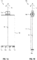
- FIGN. 1A , B show two variants of a processing tool designed as a core drill bit 10A, 10B .
- the core drill bit 10A shown is hereinafter referred to as the first core drill bit and the in FIG. 1B illustrated core drill bit 10B referred to as second core drill bit, also the first and second core drill bit 10A, 10B are summarized under the term "core drill bit”.
- the first core drill bit 10A comprises a plurality of machining segments 11A, a tubular base body 12A and a tool holder 13A.
- the machining segments 11A which are used for core drilling, are also referred to as drill segments and the tubular base body 12A is also referred to as the drill shank.
- the drill segments 11A are firmly connected to the drill shank 12A, for example by screwing, gluing, soldering or welding.
- the second core drill bit 10B comprises an annular machining segment 11B, a tubular base body 12B and a tool holder 13B.
- the ring-shaped machining segment 11B which is used for core drilling, is also referred to as a drill ring
- the tubular base body 12B is also referred to as a drill shank.
- the drill ring 11B is firmly connected to the drill shank 12B, for example by screwing, gluing, soldering or welding.
- the core drilling crown 10A, 10B is connected to a core drilling device via the tool holder 13A, 13B and is driven by the core drilling device in a direction of rotation 14 about an axis of rotation 15 during drilling operation.
- the core drill bit 10A, 10B is moved along a feed direction 16 into a workpiece to be machined, the feed direction 16 running parallel to the axis of rotation 15.
- the core drill bit 10A, 10B produces a drill core and a borehole in the workpiece to be machined.
- the drill shaft 12A, 12B is in the embodiment FIGN. 1A , B are made in one piece and the drill segments 11A or the drill ring 11B are firmly connected to the drill shank 12A, 12B.
- the drill shank 12A, 12B can be made in two parts from a first drill shank section and a second drill shank section, with the drill segments 11A or the drill ring 11B being firmly connected to the first drill shank section and the tool holder 13A, 13B firmly connected to the second drill shank section.
- the first and second drill shaft sections are connected to one another via a detachable connecting device.
- the detachable connection device is designed, for example, as a plug-and-turn connection, as in EP 2 745 965 A1 or EP 2 745 966 A1 described, trained.
- the design of the drill shaft as a one-piece or two-piece drill shaft has no effect on the construction of the drill segments 11A or the drill ring 11B.
- FIGN. 2A , B show two variants of a processing tool designed as a saw blade 20A, 20B .
- the saw blade 20A shown is referred to below as the first saw blade and the FIG. 2 B
- the saw blade 20B shown is referred to as the second saw blade, and the first and second saw blades 20A, 20B are combined under the term "saw blade”.
- the first saw blade 20A includes a plurality of machining segments 21A, a disc-shaped base body 22A and a tool holder.
- the processing segments 21A which are used for sawing, are also referred to as saw segments and the disc-shaped base body 22A is also referred to as the blade body.
- the saw segments 21A are firmly connected to the blade body 22A, for example by screwing, gluing, soldering or welding.
- the second saw blade 20B includes a plurality of machining segments 21B, a ring-shaped base body 22B and a tool holder.
- the processing segments 21B which are used for sawing, are also referred to as saw segments and the ring-shaped base body 22B is also referred to as a ring.
- the saw segments 21B are firmly connected to the ring 22B, for example by screwing, gluing, soldering or welding.
- the saw blade 20A, 20B is connected to a saw via the tool holder and is driven by the saw in a direction of rotation 24 about an axis of rotation 25 during sawing operation. During the rotation of the saw blade 20A, 20B about the axis of rotation 25, the saw blade 20A, 20B is moved along a feed direction, the feed direction running parallel to the longitudinal plane of the saw blade 20A, 20B. The saw blade 20A, 20B creates a kerf in the workpiece to be machined.
- FIG. 3 shows a machining tool designed as a cutting disk 30 .
- the cutting disc 30 comprises a plurality of machining segments 31, a base body 32 and a tool holder.
- the machining segments 31, which are used for removal, are also referred to as removal segments and the disc-shaped base body 32 is also referred to as a pot.
- the removal segments 31 are firmly connected to the pot 32, for example by screwing, gluing, soldering or welding.
- the cutting disc 30 is connected to a tool via the tool holder and is driven by the tool in the cutting operation in a direction of rotation 34 about a rotation axis 35 .
- the cutting disc 30 is moved over a workpiece to be machined, with the movement running perpendicular to the axis of rotation 35 .
- the cutting wheel 30 removes the surface of the workpiece to be machined.
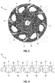
- FIG. 4 shows a processing tool designed as a cutting chain 40 .
- the cutting-off chain 40 comprises a plurality of processing segments 41, a plurality of link-shaped base bodies 42 and a plurality of connecting links 43.
- the processing segments 41 which are used for cut-off grinding, are also referred to as cutting-off segments and the link-shaped base bodies 42 are also referred to as drive links.
- the drive links 42 are connected via the connecting links 43 .
- the connecting links 43 are connected to the drive links 42 via rivet bolts.
- the rivets allow the drive links 42 to rotate relative to the connecting links 43 about an axis of rotation which runs through the center of the rivet bolts.
- the processing segments 41 are firmly connected to the drive links 42, for example by screwing, gluing, soldering or welding.
- the abrasive cutting chain 40 is connected to a tool device via a tool holder and is driven in one direction of rotation by the tool device during operation. During the rotation of the abrasive cutting chain 40, the abrasive cutting chain 40 is moved into a workpiece to be machined.
- FIG. 5 shows a machining segment 51 which was produced by means of the method according to the invention for the production of a machining segment.
- the processing segment 51 is made up of a processing zone 52 and a neutral zone 53 .
- the neutral zone 53 is required if the machining segment 51 is to be welded to the base body of a machining tool and the combination of matrix material and base body cannot be welded; in the case of weldable combinations of matrix material and base body, the neutral zone 53 can be omitted.
- the processing zone 52 is made up of a powdery or granular first matrix material 54 and first hard material particles 55 arranged according to a defined first particle pattern, and the neutral zone 53 is made up of a powdery or granular second matrix material 56 .
- matrix material includes all materials for the construction of machining segments in which hard material particles can be embedded. Matrix materials can consist of one material or be composed of a mixture of different materials. All cutting means for machining segments are summarized under the term “hard material particles”; this primarily includes individual hard material particles, composite parts made from several hard material particles and coated or encapsulated hard material particles.
- the processing segment 51 corresponds in structure and composition to the processing segments 11A, 21A, 21B, 31, 41; the machining segment 11B designed as a drill ring differs from the machining segment 51 in its ring-shaped structure.
- the machining segments can differ from one another in terms of the dimensions and the curvature of the surfaces.
- the structure of the processing segments is explained using processing segment 51 and applies to processing segments 11A, 21A, 21B, 31, 41.
- the processing segment 51 includes the first hard material particles 55 which are arranged in the first matrix material 54 .
- the hard material particles of the processing segment 51 which process a substrate, are referred to as "first hard material particles", the number of the first hard material particles 55 and the defined first particle pattern, according to which the first hard material particles 55 are arranged in the first matrix material 54, can be adapted to the requirements of the machining segment 51.
- the first hard material particles 55 generally come from a particle distribution that is characterized by a minimum diameter, a maximum diameter and a mean diameter d average .
- the machining segment 51 is connected to the base body of the machining tool with an underside 58 .
- the underside of the machining segments is usually flat, whereas the underside of machining segments for sawing has a curvature in order to be able to attach the machining segments to the curved end face of the annular or disc-shaped base body.
- the first hard material particles 55 project beyond the first matrix material 54 on an upper side 59 opposite the lower side 58 .
- FIGN. 6A-D show the production of the processing segment 51 using the method according to the invention for producing a processing segment.
- the machining segment 51 is built up from the top down from the first matrix material 54 , the first hard material particles 55 , the second matrix material 56 and a powdered support material 61 in the standing structure.
- the support material 61 is different from the first matrix material 54 and serves to support the first hard material particles 55 so that they can maintain their position according to the defined first particle pattern.
- the support material 61 has a melting temperature T melt which is greater than the melting temperature T 1 of the first matrix material 54 .
- the processing segment 51 is produced in several steps: In a first step, a support layer 62 of the support material 61 is applied and in a second step, the first hard material particles 55 are arranged in the support material 61 according to the defined first particle pattern, the first hard material particles 55 with a protrusion ⁇ are arranged in the support material 61 ( FIG. 6A ); the penetration depth d in the first hard material particle 55 is a maximum of 50% of the average particle diameter d average of the first hard material particles 55. Since the penetration depth d in the first hard material particle 55 is a maximum of 50% of the average particle diameter, it is ensured that the first hard material particles 55 in the finished machining segment 51 are securely fastened in the first matrix material 54.
- a first layer 63 of the first matrix material 54 is applied to the first hard material particles 55 and the support material 61 and melted using a powder bed fusion method ( FIG. 6B ).
- the production of the machining segment 51 continues with a sequence of steps, where the sequence can be performed once or multiple times (N times with N ⁇ 1); in the embodiment, the sequence is simply performed.
- a layer 64 of the first matrix material 54 is applied to the previous layer structure ( FIG. 6C ) and in a second step of the sequence, the layer 64 of the first matrix material 54 is melted using the powder bed fusion method.
- a layer 65 of the second matrix material 56 is applied to the previous layer structure and melted using the powder bed fusion process and thereby connected to the previous layer structure.
- FIGN. 7A-F show another machining segment 71, which was produced with the method according to the invention for producing a machining segment.
- the processing segment 71 differs from the processing segment 51 of FIG. 5 in that the processing segment 71 has only one processing zone 72 and no neutral zone.
- the processing zone 72 is made up of a powdery or granular first matrix material 74, first hard material particles 75 arranged according to a defined first particle pattern, and second hard material particles 76 arranged according to a defined second particle pattern.
- the second hard material particles 76 were arranged in the first matrix material 74 in accordance with the defined second particle pattern; alternatively, the second hard material particles 76 can be added to the first matrix material 74 as statistically distributed particles.
- the first hard material particles 75 and second hard material particles 76 generally come from particle distributions that are characterized by a minimum diameter, a maximum diameter and a mean diameter.
- the first hard material particles 75 come from a first particle distribution with a first mean diameter d mean,1 and the second hard material particles 76 come from a second particle distribution with a second mean diameter d mean,2 , the first mean diameter being larger than the second mean diameter .
- the first hard material particles 75 and second hard material particles 76 originate from the same particle distribution and have the same average diameter.
- the machining segment 71 is connected to the base body of a machining tool with an underside 78 .
- a substrate is processed by the first hard material particles 75 which are arranged on an upper side 79 opposite the underside 78 .
- the machining segment 71 is built up from the top down from the first matrix material 74 , the first hard material particles 75 , the second hard material particles 76 and a powdered support material 81 in the standing structure.
- the support material 81 is different from the first matrix material 74 and serves to support the first hard material particles 75 so that they can maintain their position according to the defined first particle pattern.
- the support material 81 has a melting temperature T melt which is greater than the melting temperature T 1 of the first matrix material 74 .
- the processing segment 71 is produced in several steps: In a first step, a support layer 82 of the support material 81 is applied and in a second step, the first hard material particles 75 are arranged in the support material 81 according to the defined first particle pattern ( FIG. 7A ), wherein the first hard material particles 75 are not completely embedded in the support material 81, but have a projection ⁇ relative to the support material 81; the penetration depth d in the first hard material particle 75 is a maximum of 50% of the first average particle diameter d average,1 of the first hard material particle 75.
- a first layer 83 of the first matrix material 74 is applied to the first hard material particle 75 and the support material 81 and by means of melted using a powder bed fusion process ( FIG. 7B )
- the production of the processing segment 71 is continued with a sequence of steps, the sequence being carried out once or multiple times (N times with N ⁇ 1); at processing segment 71, the sequence is performed twice.
- a first step of the first sequence a layer 84 of the first matrix material 74 is applied; in an intermediate step of the first sequence, the second hard material particles 76 are arranged in the layer 84 of the first matrix material 74 according to the defined second particle pattern ( FIG. 7C ) and in a second step of the first sequence, the layer 84 of the first matrix material 74 is melted using the powder bed fusion process and connected to the previous layer structure ( FIG. 7D ).
- a further layer 85 of the first matrix material 74 is applied; in an intermediate step of the second sequence, the second hard material particles 76 are arranged in the layer 85 of the first matrix material 74 according to the defined second particle pattern ( FIG. 7E ) and in a second step of the second sequence the layer 85 of the first matrix material 74 is melted using the powder bed fusion method and connected to the previous layer structure.
- the machining segment 71 is complete and is removed from the support material 81 ( FIG. 7F ).
Abstract
Verfahren zur Herstellung eines Bearbeitungssegmentes (51) aus einem ersten pulverförmigen Matrixwerkstoff (54) und ersten Hartstoffpartikeln (55), die gemäss einem definierten ersten Partikelmuster angeordnet werden mit den Schritten:▪ Auftragen eines Stützmaterials (61) als Stützschicht (62), wobei die Schmelztemperatur des Stützmaterials (61) grösser als die Schmelztemperatur des ersten Matrixwerkstoffes (54) ist,▪ Anordnen der ersten Hartstoffpartikel (55) gemäß dem definierten ersten Partikelmuster im Stützmaterial (61), wobei die ersten Hartstoffpartikel (55) mit einer Eindringtiefe (d<sub>in</sub>) im Stützmaterial (61) angeordnet werden,▪ Auftragen einer ersten Schicht (63) des ersten Matrixwerkstoffs (54) auf die ersten Hartstoffpartikel (55) und das Stützmaterial (61) und Aufschmelzen der ersten Schicht (63) mittels eines Powder bed fusion-Verfahrens und▪ Ausführen einer Folge von mehreren Schritten, die N-fach, N ≥ 1 ausgeführt wird, wobei in einem ersten Schritt der Folge eine Schicht (64) des ersten Matrixwerkstoffs (54) auf den Schichtaufbau aufgetragen wird und in einem zweiten Schritt der Folge die Schicht (64) des ersten Matrixwerkstoffs (54) mittels des Powder bed fusion-Verfahrens aufgeschmolzen und mit dem Schichtaufbau verbunden wird.Method for producing a machining segment (51) from a first matrix material (54) in powder form and first hard material particles (55), which are arranged according to a defined first particle pattern, with the steps: ▪ Application of a supporting material (61) as a supporting layer (62), the melting temperature of the support material (61) is greater than the melting temperature of the first matrix material (54), ▪ arranging the first hard material particles (55) according to the defined first particle pattern in the support material (61), the first hard material particles (55) having a penetration depth (d< sub>in</sub>) are arranged in the support material (61), ▪ applying a first layer (63) of the first matrix material (54) to the first hard material particles (55) and the support material (61) and melting the first layer (63 ) by means of a powder bed fusion method and ▪ performing a sequence of multiple steps that is performed N times, N ≥ 1, wherein in a first step of the sequence e A layer (64) of the first matrix material (54) is applied to the layer structure and in a second step in sequence the layer (64) of the first matrix material (54) is melted using the powder bed fusion process and connected to the layer structure.
Description
Die vorliegende Erfindung betrifft ein Verfahren zur Herstellung eines Bearbeitungssegmentes gemäß dem Oberbegriff des Anspruchs 1.The present invention relates to a method for producing a machining segment according to the preamble of
Bearbeitungswerkzeuge, wie Kernbohrkronen, Sägeblätter, Abtragscheiben und Trennschleifketten, umfassen Bearbeitungssegmente, die an einem rohr-, scheiben- oder ringförmigen Grundkörper befestigt werden, wobei die Bearbeitungssegmente durch Schweißen, Löten oder Kleben mit dem Grundkörper verbunden werden. Abhängig vom Bearbeitungsverfahren des Bearbeitungswerkzeugs werden Bearbeitungssegmente, die zum Kernbohren eingesetzt werden, als Bohrsegmente, Bearbeitungssegmente, die zum Sägen eingesetzt werden, als Sägesegmente, Bearbeitungssegmente, die zum Abtragen eingesetzt werden, als Abtragsegmente und Bearbeitungssegmente, die zum Trennschleifen eingesetzt werden, als Trennschleifsegmente bezeichnet.Machining tools such as core drilling crowns, saw blades, abrasive discs and abrasive chains include machining segments that are attached to a tubular, disc-shaped or ring-shaped base body, the machining segments being connected to the base body by welding, soldering or gluing. Depending on the processing method of the processing tool, processing segments that are used for core drilling are referred to as drilling segments, processing segments that are used for sawing as sawing segments, processing segments that are used for removal as removal segments and processing segments that are used for cut-off grinding as cut-off segments .
Bearbeitungssegmente für Kernbohrkronen, Sägeblätter, Abtragscheiben und Trennschleifketten werden aus einem Matrixwerkstoff und Hartstoffpartikeln hergestellt, wobei die Hartstoffpartikel statistisch verteilt vorliegen können oder gemäß einem definierten Partikelmuster im Matrixwerkstoff angeordnet sind. Bei Bearbeitungssegmenten mit statistisch verteilten Hartstoffpartikeln werden der Matrixwerkstoff und die Hartstoffpartikel gemischt, die Mischung wird in eine passende Werkzeugform eingefüllt und zum Bearbeitungssegment weiterverarbeitet. Bei Bearbeitungssegmenten mit gesetzten Hartstoffpartikeln wird ein Grünling schichtweise aus Matrixwerkstoff aufgebaut, in den die Hartstoffpartikel gemäß dem definierten Partikelmuster platziert werden. Bei Bearbeitungssegmenten, die mit dem Grundkörper des Bearbeitungswerkzeuges verschweißt werden, hat sich der Aufbau aus einer Bearbeitungszone und einer Neutralzone bewährt. Die Bearbeitungszone wird aus einem ersten Matrixwerkstoff und die Neutralzone aus einem zweiten Matrixwerkstoff, der vom ersten Matrixwerkstoff verschieden ist, aufgebaut.Machining segments for core drilling crowns, saw blades, abrasive discs and cutting chains are made from a matrix material and hard material particles, whereby the hard material particles can be randomly distributed or arranged according to a defined particle pattern in the matrix material. In the case of machining segments with statistically distributed hard material particles, the matrix material and the hard material particles are mixed, the mixture is poured into a suitable tool mold and further processed into the machining segment. In the case of machining segments with set hard material particles, a green compact is built up in layers from matrix material, in which the hard material particles are placed according to the defined particle pattern. In the case of machining segments that are welded to the base body of the machining tool, the structure of a machining zone and a neutral zone has proven itself. The processing zone is made up of a first matrix material and the neutral zone is made up of a second matrix material, which is different from the first matrix material.
Bearbeitungswerkzeuge, die als Kernbohrkrone, Sägeblatt, Abtragscheibe oder Trennschleifkette ausgebildet sind und für die Nassbearbeitung von Betonwerkstoffen vorgesehen sind, sind für die Trockenbearbeitung von Betonwerkstoffen nur bedingt geeignet. Bei der Nassbearbeitung von Betonwerkstoffen entsteht ein abrasiver Betonschlamm, der den Bearbeitungsprozess unterstützt und zu einem Selbstschärfen der Bearbeitungssegmente während der Bearbeitung führt. Der Matrixwerkstoff wird durch den abrasiven Betonschlamm abgetragen und neue Hartstoffpartikel werden freigelegt. Bei der Trockenbearbeitung von Betonwerkstoffen kann sich kein abrasiver Betonschlamm bilden, der den Bearbeitungsprozess unterstützen kann. Die Hartstoffpartikel werden schnell stumpf und die Bearbeitungsrate sinkt. Durch den fehlenden Betonschlamm verschleißt der Matrixwerkstoff zu langsam und tiefer liegende Hartstoffpartikel können nicht freigelegt werden. Bei bekannten Bearbeitungswerkzeugen zur Nassbearbeitung weisen der Matrixwerkstoff und die Hartstoffpartikel ähnliche Verschleißraten auf.Machining tools that are designed as core drill bits, saw blades, cutting discs or abrasive chains and are intended for wet machining of concrete materials are only suitable to a limited extent for dry machining of concrete materials. During the wet machining of concrete materials, an abrasive concrete sludge is created, which supports the machining process and leads to a self-sharpening of the machining segments during machining. The matrix material is removed by the abrasive concrete slurry and new hard material particles are exposed. When dry machining concrete materials, no abrasive concrete sludge can form that can support the machining process. The hard material particles quickly become blunt and the processing rate drops. Due to the lack of concrete slurry, the matrix material wears out too slowly and deeper-lying hard material particles cannot be exposed. In known machining tools for wet machining, the matrix material and the hard material particles have similar wear rates.
Die Aufgabe der vorliegenden Erfindung besteht darin, ein alternatives Verfahren zur Herstellung eines Bearbeitungssegmentes zu entwickeln, mit dem Bearbeitungssegmente hergestellt werden können, die für die Trockenbearbeitung von Betonwerkstoffen geeignet sind. Dabei soll das Bearbeitungssegment bei der Trockenbearbeitung von Betonwerkstoffen eine hohe Bearbeitungsrate und eine möglichst lange Lebensdauer aufweisen.The object of the present invention is to develop an alternative method for producing a machining segment, with which machining segments can be manufactured that are suitable for the dry machining of concrete materials. The processing segment should have a high processing rate and the longest possible service life during the dry processing of concrete materials.
Diese Aufgabe wird bei dem eingangs genannten Verfahren erfindungsgemäß durch die Merkmale des unabhängigen Anspruchs 1 gelöst. Vorteilhafte Weiterbildungen sind in den abhängigen Ansprüchen angegeben.In the case of the method mentioned at the outset, this object is achieved according to the invention by the features of
Das Verfahren zur Herstellung eines Bearbeitungssegmentes ist erfindungsgemäß gekennzeichnet durch die Schritte:
- ▪ Auftragen eines Stützmaterials als Stützschicht, wobei die Schmelztemperatur des Stützmaterials grösser als die Schmelztemperatur des ersten Matrixwerkstoffes,
- ▪ Anordnen der ersten Hartstoffpartikel gemäß dem definierten ersten Partikelmuster im Stützmaterial, wobei die ersten Hartstoffpartikel mit einer Eindringtiefe im Stützmaterial angeordnet werden,
- ▪ Auftragen einer ersten Schicht des ersten Matrixwerkstoffs auf die ersten Hartstoffpartikel und das Stützmaterial und Aufschmelzen der ersten Schicht mittels eines Powder bed fusion-Verfahrens und
- ▪ Ausführen einer Folge von mehreren Schritten, die N-fach, N ≥ 1 ausgeführt wird, wobei in einem ersten Schritt der Folge eine Schicht des ersten Matrixwerkstoffs auf den Schichtaufbau aufgetragen wird und in einem zweiten Schritt der Folge die Schicht des ersten Matrixwerkstoffs mittels des Powder bed fusion-Verfahrens aufgeschmolzen und mit dem Schichtaufbau verbunden wird.
- ▪ Application of a support material as a support layer, with the melting temperature of the support material being greater than the melting temperature of the first matrix material,
- ▪ arranging the first hard material particles according to the defined first particle pattern in the support material, the first hard material particles being arranged with a penetration depth in the support material,
- ▪ Application of a first layer of the first matrix material to the first hard material particles and the support material and melting of the first layer using a powder bed fusion process and
- ▪ Execution of a sequence of several steps, which is executed N-times, N ≥ 1, wherein in a first step of the sequence a layer of the first matrix material is applied to the layer structure and in a second step of the sequence the layer of the first matrix material is melted by means of the powder bed fusion process and connected to the layer structure.
Das erfindungsgemäße Verfahren zur Herstellung eines Bearbeitungssegmentes zeichnet sich dadurch aus, dass die Bearbeitungssegmente stehend von oben nach unten aufgebaut werden, d.h. die Aufbaurichtung verläuft senkrecht zur Höhenrichtung zwischen der Unterseite und Oberseite der Bearbeitungssegmente. Der Überstand der ersten Hartstoffpartikel an der Oberseite der Bearbeitungssegmente wird mithilfe des Stützmaterials erzeugt, das vom ersten Matrixwerkstoff verschieden ist. Dabei weist das Stützmaterial eine Schmelztemperatur auf, die höher als die Schmelztemperatur des ersten Matrixwerkstoffes ist. Dadurch, dass die Schmelztemperatur des Stützmaterials höher als die Schmelztemperatur des ersten Matrixwerkstoffes ist, bleibt das Stützmaterial pulverförmig und kann problemlos vom fertigen Bearbeitungssegment entfernt werden. Beim Aufschmelzen des ersten Matrixwerkstoffs bleibt das Stützmaterial in seinem pulverförmigen Zustand und fixiert die Position der ersten Hartstoffpartikel.The method according to the invention for producing a machining segment is characterized in that the machining segments are built up vertically from top to bottom, i.e. the direction of assembly runs perpendicular to the height direction between the bottom and top of the machining segments. The overhang of the first hard material particles on the upper side of the machining segments is created using the support material, which is different from the first matrix material. The support material has a melting temperature that is higher than the melting temperature of the first matrix material. Due to the fact that the melting temperature of the support material is higher than the melting temperature of the first matrix material, the support material remains in powder form and can be removed from the finished machining segment without any problems. When the first matrix material is melted, the support material remains in its powdery state and fixes the position of the first hard material particles.
Nach dem Auftragen wird der erste Matrixwerkstoff aufgeschmolzen und mit dem Schichtaufbau verbunden. Zum Aufschmelzen des ersten Matrixwerkstoffs eignen sich sämtliche bekannten sowie zukünftigen Powder bed fusion-Verfahren mit Laserstrahl oder Elektronenstrahl. Welches Powder bed fusion-Verfahren verwendet wird, spielt für das erfindungsgemäße Verfahren zur Herstellung eines Bearbeitungssegmentes keine Rolle. Wichtig ist, dass der erste Matrixwerkstoff aufgeschmolzen und mit dem darunter liegenden Schichtaufbau verbunden wird.After application, the first matrix material is melted and connected to the layer structure. All known and future powder bed fusion processes using a laser beam or electron beam are suitable for melting the first matrix material. Which powder bed fusion method is used is irrelevant for the method according to the invention for producing a machining segment. It is important that the first matrix material is melted and connected to the underlying layer structure.
Das erfindungsgemäße Verfahren ermöglicht die Herstellung von Bearbeitungssegmenten, die an ihrer Oberseite erste Hartstoffpartikel mit einem Überstand aufweisen und daher für die Trockenbearbeitung von Betonwerkstoffen geeignet sind. Das erfindungsgemäße Verfahren hat den Vorteil, dass am Ende des Schichtaufbaus das fertige Bearbeitungssegment entnommen werden kann und kein weiterer Verarbeitungsprozess in Form von Sintern oder Heißpressen erforderlich ist.The method according to the invention enables the production of machining segments which have first hard material particles with a protrusion on their upper side and are therefore suitable for the dry machining of concrete materials. The method according to the invention has the advantage that the finished machining segment can be removed at the end of the layer structure and no further processing in the form of sintering or hot pressing is required.
In einer ersten Weiterentwicklung umfasst die Folge einen Zwischenschritt, der zwischen dem ersten Schritt und zweiten Schritt der Folge ausgeführt wird, wobei im Zwischenschritt zweite Hartstoffpartikel gemäss einem definierten zweiten Partikelmuster in der Schicht des ersten Matrixwerkstoffs angeordnet werden. Während der Bearbeitung mit dem Bearbeitungssegment kann es durch Reibung zu einem verstärkten Verschleiß des ersten Matrixwerkstoffes an den Seitenflächen des Bearbeitungssegmentes kommen. Dieser Verschleiß kann durch die zweiten Hartstoffpartikel reduziert werden. Die Anordnung der zweiten Hartstoffpartikel gemäß dem definierten zweiten Partikelmuster hat gegenüber statistisch verteilten zweiten Hartstoffpartikel den Vorteil, dass die zweiten Hartstoffpartikel in den Seitenflächen angeordnet werden können und den Verschleiß an den Seitenflächen reduzieren können.In a first further development, the sequence includes an intermediate step that is carried out between the first step and the second step of the sequence, wherein second hard material particles are arranged in the intermediate step according to a defined second particle pattern in the layer of the first matrix material. During machining with the machining segment, friction can lead to increased wear of the first matrix material on the side surfaces of the machining segment. This wear and tear can be reduced by the second hard material particles. The arrangement of the second hard material particles according to the defined second particle pattern has the advantage over statistically distributed second hard material particles that the second hard material particles can be arranged in the side surfaces and can reduce wear on the side surfaces.
In einer alternativen Weiterentwicklung werden dem ersten Matrixwerkstoff zweite Hartstoffpartikel beigemischt, wobei ein mittlerer Partikeldurchmesser der zweiten Hartstoffpartikel kleiner als ein mittlerer Partikeldurchmesser der ersten Hartstoffpartikel ist. Während der Bearbeitung mit dem Bearbeitungssegment kann es durch Reibung zu einem verstärkten Verschleiß des ersten Matrixwerkstoffes an den Seitenflächen des Bearbeitungssegmentes kommen. Dieser Verschleiß kann durch die zweiten Hartstoffpartikel reduziert werden.In an alternative further development, second hard material particles are admixed to the first matrix material, with an average particle diameter of the second hard material particles being smaller than an average particle diameter of the first hard material particles. During machining with the machining segment, friction can lead to increased wear of the first matrix material on the side surfaces of the machining segment. This wear can be reduced by the second hard material particles.
Bevorzugt wird nach der N-ten Folge mindestens eine Schicht eines zweiten Matrixwerkstoffs aufgetragen und mittels des Powder bed fusion-Verfahrens aufgeschmolzen und mit dem Schichtaufbau verbunden, wobei der zweite Matrixwerkstoff vom ersten Matrixwerkstoff verschieden ist. Der zweite Matrixwerkstoff ermöglicht den Aufbau einer Neutralzone. Neutralzonen werden bei Bearbeitungssegmenten genutzt, wenn die Bearbeitungssegmente mit dem Grundkörper eines Bearbeitungswerkzeuges verschweißt werden sollen und die Kombination aus erstem Matrixwerkstoff und Grundkörper nicht schweißbar ist. Der zweite Matrixwerkstoff wird im Hinblick auf eine gute Schweißbarkeit in Kombination mit dem Grundkörper ausgewählt.After the Nth sequence, at least one layer of a second matrix material is preferably applied and melted using the powder bed fusion process and connected to the layer structure, the second matrix material being different from the first matrix material. The second matrix material enables the creation of a neutral zone. Neutral zones are used for machining segments when the machining segments are to be welded to the base body of a machining tool and the combination of the first matrix material and the base body cannot be welded. The second matrix material is selected with regard to good weldability in combination with the base body.
Bevorzugt weisen die ersten Hartstoffpartikel einen mittleren Partikeldurchmesser auf und werden maximal bis zum halben mittleren Partikeldurchmesser in das Stützmaterial eingebettet. Der Überstand der ersten Hartstoffpartikel an der Oberseite der Bearbeitungssegmente entspricht der Eindringtiefe, mit der die ersten Hartstoffpartikel in das Stützmaterial eingebettet werden. Da die Eindringtiefe der ersten Hartstoffpartikel maximal 50 % des mittleren Partikeldurchmessers der ersten Hartstoffpartikel beträgt, ist gewährleistet, dass die ersten Hartstoffpartikel beim fertigen Bearbeitungssegment sicher im ausgeschmolzenen ersten Matrixwerkstoff befestigt sind.The first hard material particles preferably have an average particle diameter and are embedded in the support material up to a maximum of half the average particle diameter. The overhang of the first hard material particles on the upper side of the machining segments corresponds to the penetration depth with which the first hard material particles are embedded in the support material. Since the penetration depth of the first hard material particles is a maximum of 50% of the mean particle diameter of the first hard material particles, it is ensured that the first hard material particles are securely fastened in the melted-out first matrix material in the finished machining segment.
Ausführungsbeispiele der Erfindung werden nachfolgend anhand der Zeichnung beschrieben. Diese soll die Ausführungsbeispiele nicht notwendigerweise maßstäblich darstellen, vielmehr ist die Zeichnung, wo zur Erläuterung dienlich, in schematischer und/oder leicht verzerrter Form ausgeführt. Dabei ist zu berücksichtigen, dass vielfältige Modifikationen und Änderungen betreffend die Form und das Detail einer Ausführungsform vorgenommen werden können, ohne von der allgemeinen Idee der Erfindung abzuweichen. Die allgemeine Idee der Erfindung ist nicht beschränkt auf die exakte Form oder das Detail der im Folgenden gezeigten und beschriebenen bevorzugten Ausführungsform oder beschränkt auf einen Gegenstand, der eingeschränkt wäre im Vergleich zu dem in den Ansprüchen beanspruchten Gegenstand. Bei gegebenen Bemessungsbereichen sollen auch innerhalb der genannten Grenzen liegende Werte als Grenzwerte offenbart und beliebig einsetzbar und beanspruchbar sein. Der Einfachheit halber sind nachfolgend für identische oder ähnliche Teile oder Teile mit identischer oder ähnlicher Funktion gleiche Bezugszeichen verwendet.Exemplary embodiments of the invention are described below with reference to the drawing. This is not necessarily intended to represent the exemplary embodiments to scale; instead, the drawing is in schematic and/or slightly distorted form where it is useful for explanation. In this context, it must be taken into account that various modifications and changes relating to the form and detail of an embodiment are made can without deviating from the general idea of the invention. The general idea of the invention is not limited to the exact form or detail of the preferred embodiment shown and described below, or limited to any subject matter which would be limited compared to the subject matter claimed in the claims. In the case of given design ranges, values lying within the specified limits should also be disclosed as limit values and should be able to be used and claimed as desired. For the sake of simplicity, the same reference numbers are used below for identical or similar parts or parts with an identical or similar function.
Es zeigen:
- FIGN. 1A, B
- zwei Varianten eines als Kernbohrkrone ausgebildeten Bearbeitungswerkzeuges;
- FIGN. 2A, B
- zwei Varianten eines als Sägeblatt ausgebildeten Bearbeitungswerkzeuges;
- FIG. 3
- ein als Abtragscheibe ausgebildetes Bearbeitungswerkzeug;
- FIG. 4
- ein als Trennschleifkette ausgebildetes Bearbeitungswerkzeug;
- FIGN. 5A-C
- einen Grünling (
FIG. 5A ), der zu einem Pressling verdichtet (FIG. 5B ) und zu einem Bearbeitungssegment weiterverarbeitet wird (FIG. 5C ); - FIGN. 6A-D
- die Herstellung des Grünlings der
FIG. 5A mithilfe des erfindungsgemäßen Verfahrens zur Herstellung eines Grünlings; - FIGN. 7A, B
- einen Grünling (
FIG. 7A ), der zu einem Bearbeitungssegment weiterverarbeitet wird (FIG. 7B ).
- FIGN. 1A, B
- two variants of a processing tool designed as a core drill bit;
- FIGN. 2A, B
- two variants of a processing tool designed as a saw blade;
- FIG. 3
- a machining tool designed as a cutting disk;
- FIG. 4
- a processing tool designed as a cutting chain;
- FIGN. 5A-C
- a green body (
FIG. 5A ), which compacts into a pellet (FIG. 5B ) and further processed into a processing segment (FIG. 5C ); - FIGN. 6A-D
- the production of the green compact
FIG. 5A using the method of the present invention for producing a green compact; - FIGN. 7A, B
- a green body (
FIG. 7A ), which is further processed into a machining segment (FIG. 7B ).
Die erste Kernbohrkrone 10A umfasst mehrere Bearbeitungssegmente 11A, einen rohrförmig ausgebildeten Grundkörper 12A und eine Werkzeugaufnahme 13A. Die Bearbeitungssegmente 11A, die zum Kernbohren eingesetzt werden, werden auch als Bohrsegmente bezeichnet und der rohrförmig ausgebildete Grundkörper 12A wird auch als Bohrschaft bezeichnet. Die Bohrsegmente 11A sind fest mit dem Bohrschaft 12A verbunden, beispielsweise durch Schrauben, Kleben, Löten oder Schweißen.The first
Die zweite Kernbohrkrone 10B umfasst ein ringförmiges Bearbeitungssegment 11B, einen rohrförmig ausgebildeten Grundkörper 12B und eine Werkzeugaufnahme 13B. Das ringförmige Bearbeitungssegment 11B, das zum Kernbohren eingesetzt wird, wird auch als Bohrring bezeichnet und der rohrförmig ausgebildete Grundkörper 12B wird auch als Bohrschaft bezeichnet. Der Bohrring 11B ist fest mit dem Bohrschaft 12B verbunden, beispielsweise durch Schrauben, Kleben, Löten oder Schweißen.The second
Die Kernbohrkrone 10A, 10B wird über die Werkzeugaufnahme 13A, 13B mit einem Kernbohrgerät verbunden und im Bohrbetrieb vom Kernbohrgerät in einer Drehrichtung 14 um eine Drehachse 15 angetrieben. Während der Drehung der Kernbohrkrone 10A, 10B um die Drehachse 15 wird die Kernbohrkrone 10A, 10B entlang einer Vorschubrichtung 16 in ein zu bearbeitendes Werkstück bewegt, wobei die Vorschubrichtung 16 parallel zur Drehachse 15 verläuft. Die Kernbohrkrone 10A, 10B erzeugt im zu bearbeitenden Werkstück einen Bohrkern und ein Bohrloch.The
Der Bohrschaft 12A, 12B ist im Ausführungsbeispiel der
Das erste Sägeblatt 20A umfasst mehrere Bearbeitungssegmente 21A, einen scheibenförmig ausgebildeten Grundkörper 22A und eine Werkzeugaufnahme. Die Bearbeitungssegmente 21A, die zum Sägen eingesetzt werden, werden auch als Sägesegmente bezeichnet und der scheibenförmig ausgebildete Grundkörper 22A wird auch als Stammblatt bezeichnet. Die Sägesegmente 21A sind fest mit dem Stammblatt 22A verbunden, beispielsweise durch Schrauben, Kleben, Löten oder Schweißen.The
Das zweite Sägeblatt 20B umfasst mehrere Bearbeitungssegmente 21B, einen ringförmig ausgebildeten Grundkörper 22B und eine Werkzeugaufnahme. Die Bearbeitungssegmente 21B, die zum Sägen eingesetzt werden, werden auch als Sägesegmente bezeichnet und der ringförmig ausgebildete Grundkörper 22B wird auch als Ring bezeichnet. Die Sägesegmente 21B sind fest mit dem Ring 22B verbunden, beispielsweise durch Schrauben, Kleben, Löten oder Schweißen.The
Das Sägeblatt 20A, 20B wird über die Werkzeugaufnahme mit einer Säge verbunden und im Sägebetrieb von der Säge in einer Drehrichtung 24 um eine Drehachse 25 angetrieben. Während der Drehung des Sägeblattes 20A, 20B um die Drehachse 25 wird das Sägeblatt 20A, 20B entlang einer Vorschubrichtung bewegt, wobei die Vorschubrichtung parallel zur Längsebene des Sägeblattes 20A, 20B verläuft. Das Sägeblatt 20A, 20B erzeugt im zu bearbeitenden Werkstück einen Sägeschlitz.The
Die Abtragscheibe 30 wird über die Werkzeugaufnahme mit einem Werkzeuggerät verbunden und im Abtragbetrieb vom Werkzeuggerät in einer Drehrichtung 34 um eine Drehachse 35 angetrieben. Während der Drehung der Abtragscheibe 30 um die Drehachse 35 wird die Abtragscheibe 30 über ein zu bearbeitendes Werkstück bewegt, wobei die Bewegung der senkrecht zur Drehachse 35 verläuft. Die Abtragscheibe 30 entfernt die Oberfläche des zu bearbeitenden Werkstücks.The
Die Treibglieder 42 werden über die Verbindungsglieder 43 verbunden. Im Ausführungsbeispiel sind die Verbindungsglieder 43 über Nietbolzen mit den Treibgliedern 42 verbunden. Die Nietbolzen ermöglichen eine Drehung der Treibglieder 42 relativ zu den Verbindungsgliedern 43 um eine Drehachse, die durch das Zentrum der Nietbolzen verläuft. Die Bearbeitungssegmente 41 sind fest mit den Treibgliedern 42 verbunden, beispielsweise durch Schrauben, Kleben, Löten oder Schweißen.The drive links 42 are connected via the connecting
Die Trennschleifkette 40 wird über eine Werkzeugaufnahme mit einem Werkzeuggerät verbunden und im Betrieb vom Werkzeuggerät in einer Drehrichtung angetrieben. Während der Drehung der Trennschleifkette 40 wird die Trennschleifkette 40 in ein zu bearbeitendes Werkstück bewegt.The
Die Bearbeitungszone 52 ist aus einem pulver- oder granulatförmigen ersten Matrixwerkstoff 54 und ersten Hartstoffpartikeln 55, die gemäß einem definierten ersten Partikelmuster angeordnet sind, aufgebaut und die Neutralzone 53 ist aus einem pulver- oder granulatförmigen zweiten Matrixwerkstoff 56 aufgebaut. Unter dem Begriff "Matrixwerkstoff" werden sämtliche Werkstoffe zum Aufbau von Bearbeitungssegmenten zusammengefasst, in die Hartstoffpartikel eingebettet werden können. Matrixwerkstoffe können aus einem Werkstoff bestehen oder als Gemisch aus verschiedenen Werkstoffen zusammengesetzt sein. Unter dem Begriff "Hartstoffpartikel" werden sämtliche Schneidmittel für Bearbeitungssegmente zusammengefasst; dazu gehören vor allem einzelne Hartstoffpartikel, Verbundteile aus mehreren Hartstoffpartikeln und beschichtete oder gekapselte Hartstoffpartikel.The
Das Bearbeitungssegment 51 entspricht vom Aufbau und der Zusammensetzung den Bearbeitungssegmenten 11A, 21A, 21B, 31, 41; das als Bohrring ausgebildete Bearbeitungssegment 11B unterscheidet sich durch seinen ringförmigen Aufbau vom Bearbeitungssegment 51. Die Bearbeitungssegmente können sich in den Abmessungen und in den Krümmungen der Oberflächen voneinander unterscheiden. Der Aufbau der Bearbeitungssegmente wird anhand des Bearbeitungssegmentes 51 erklärt und gilt für die Bearbeitungssegmente 11A, 21A, 21B, 31, 41.The
Das Bearbeitungssegment 51 umfasst die ersten Hartstoffpartikel 55, die im ersten Matrixwerkstoff 54 angeordnet sind. Als "erste Hartstoffpartikel" werden die Hartstoffpartikel des Bearbeitungssegmentes 51 bezeichnet, die einen Untergrund bearbeiten, wobei die Anzahl der ersten Hartstoffpartikel 55 und das definierte erste Partikelmuster, gemäß dem die ersten Hartstoffpartikel 55 im ersten Matrixwerkstoff 54 angeordnet sind, an die Anforderungen des Bearbeitungssegmentes 51 angepasst werden. Die ersten Hartstoffpartikel 55 entstammen in der Regel einer Partikelverteilung, die durch einen minimalen Durchmesser, einen maximalen Durchmesser und einen mittleren Durchmesser dmittel charakterisiert ist.The
Das Bearbeitungssegment 51 wird mit einer Unterseite 58 mit dem Grundkörper des Bearbeitungswerkzeuges verbunden. Bei Bearbeitungssegmenten zum Kernbohren und Bearbeitungssegmenten zum Abtragen ist die Unterseite der Bearbeitungssegmente in der Regel eben ausgebildet, wohingegen die Unterseite bei Bearbeitungssegmenten zum Sägen eine Krümmung aufweist, um die Bearbeitungssegmente an der gekrümmten Stirnfläche der ring- oder scheibenförmigen Grundkörper befestigen zu können. Bei dem in
Die Herstellung des Bearbeitungssegmentes 51 erfolgt in mehreren Schritten: In einem ersten Schritt wird eine Stützschicht 62 des Stützmaterials 61 aufgetragen und in einem zweiten Schritt werden die ersten Hartstoffpartikel 55 gemäß dem definierten ersten Partikelmuster im Stützmaterial 61 angeordnet, wobei die ersten Hartstoffpartikel 55 mit einem Überstand δ im Stützmaterial 61 angeordnet werden (
In einem dritten Schritt wird eine erste Schicht 63 des ersten Matrixwerkstoffs 54 auf die ersten Hartstoffpartikel 55 und das Stützmaterial 61 aufgetragen und mittels eines Powder bed fusion-Verfahrens aufgeschmolzen (
Im Anschluss an die Folge wird in einem weiteren Schritt des erfindungsgemäßen Verfahrens eine Schicht 65 des zweiten Matrixwerkstoffs 56 auf den bisherigen Schichtaufbau aufgetragen und mittels des Powder bed fusion-Verfahrens aufgeschmolzen und dabei mit dem bisherigen Schichtaufbau verbunden.Following the sequence, in a further step of the method according to the invention, a
Das Bearbeitungssegment 71 unterscheidet sich vom Bearbeitungssegment 51 der
Während der Bearbeitung eines Untergrundes mit dem Bearbeitungssegment 71 kann es durch Reibung mit dem Untergrund zu einem verstärkten Verschleiß des ersten Matrixwerkstoffes 74 an den Seitenflächen des Bearbeitungssegmentes 71 kommen. Dieser Verschleiß kann durch die zweiten Hartstoffpartikel 76 reduziert werden. Beim Bearbeitungssegment 71 wurden die zweiten Hartstoffpartikel 76 gemäß dem definierten zweiten Partikelmuster im ersten Matrixwerkstoff 74 angeordnet; alternativ können die zweiten Hartstoffpartikel 76 als statistisch verteilte Partikel dem ersten Matrixwerkstoff 74 beigemischt werden.During the processing of a subsurface with the
Die ersten Hartstoffpartikel 75 und zweiten Hartstoffpartikel 76 entstammen in der Regel Partikelverteilungen, die durch einen minimalen Durchmesser, einen maximalen Durchmesser und einen mittleren Durchmesser charakterisiert sind. Beim Bearbeitungssegment 71 entstammen die ersten Hartstoffpartikel 75 einer ersten Partikelverteilung mit einem ersten mittleren Durchmesser dmittel,1 und die zweiten Hartstoffpartikel 76 einer zweiten Partikelverteilung mit einem zweiten mittleren Durchmesser dmittel,2, wobei der erste mittlere Durchmesser grösser als der zweite mittlere Durchmesser ist. Alternativ können die ersten Hartstoffpartikel 75 und zweiten Hartstoffpartikel 76 der gleichen Partikelverteilung entstammen und den gleichen mittleren Durchmesser aufweisen.The first
Das Bearbeitungssegment 71 wird mit einer Unterseite 78 mit dem Grundkörper eines Bearbeitungswerkzeuges verbunden. Die Bearbeitung eines Untergrundes erfolgt durch die ersten Hartstoffpartikel 75, die an einer der Unterseite 78 gegenüberliegenden Oberseite 79 angeordnet sind. Das Bearbeitungssegment 71 wird im stehenden Aufbau von oben nach unten aus dem ersten Matrixwerkstoff 74, den ersten Hartstoffpartikeln 75, den zweiten Hartstoffpartikein 76 und einem pulverförmigen Stützmaterial 81 aufgebaut. Das Stützmaterial 81 ist vom ersten Matrixwerkstoff 74 verschieden und dient dazu, die ersten Hartstoffpartikel 75 zu stützen, so dass diese ihre Position gemäß dem definierten ersten Partikelmuster einhalten können. Das Stützmaterial 81 weist eine Schmelztemperatur Tschmelz auf, die grösser als die Schmelztemperatur T1 des ersten Matrixwerkstoffes 74 ist.The
Die Herstellung des Bearbeitungssegmentes 71 erfolgt in mehreren Schritten: In einem ersten Schritt wird eine Stützschicht 82 des Stützmaterials 81 aufgetragen und in einem zweiten Schritt werden die ersten Hartstoffpartikel 75 gemäß dem definierten ersten Partikelmuster im Stützmaterial 81 angeordnet (
Die Herstellung des Bearbeitungssegmentes 71 wird mit einer Folge von Schritten fortgesetzt, wobei die Folge einfach oder mehrfach (N-fach mit N ≥ 1) durchgeführt wird; beim Bearbeitungssegment 71 wird die Folge zweifach durchgeführt. In einem ersten Schritt der ersten Folge wird eine Schicht 84 des ersten Matrixwerkstoffs 74 aufgetragen, in einem Zwischenschritt der ersten Folge werden die zweiten Hartstoffpartikel 76 gemäß dem definierten zweiten Partikelmuster in der Schicht 84 des ersten Matrixwerkstoffs 74 angeordnet (
In einem ersten Schritt der zweiten Folge wird eine weitere Schicht 85 des ersten Matrixwerkstoffs 74 aufgetragen, in einem Zwischenschritt der zweiten Folge werden die zweiten Hartstoffpartikel 76 gemäß dem definierten zweiten Partikelmuster in der Schicht 85 des ersten Matrixwerkstoffs 74 angeordnet (
Claims (5)
Priority Applications (5)
| Application Number | Priority Date | Filing Date | Title |
|---|---|---|---|
| EP20214058.8A EP4015108A1 (en) | 2020-12-15 | 2020-12-15 | Method for producing a processing segment |
| EP21824589.2A EP4263093A1 (en) | 2020-12-15 | 2021-12-13 | Method for producing a machining segment |
| KR1020237023722A KR20230119190A (en) | 2020-12-15 | 2021-12-13 | Machining Segment Manufacturing Method |
| PCT/EP2021/085471 WO2022128907A1 (en) | 2020-12-15 | 2021-12-13 | Method for producing a machining segment |
| US18/267,343 US20240058863A1 (en) | 2020-12-15 | 2021-12-13 | Method for producing a machining segment |
Applications Claiming Priority (1)
| Application Number | Priority Date | Filing Date | Title |
|---|---|---|---|
| EP20214058.8A EP4015108A1 (en) | 2020-12-15 | 2020-12-15 | Method for producing a processing segment |
Publications (1)
| Publication Number | Publication Date |
|---|---|
| EP4015108A1 true EP4015108A1 (en) | 2022-06-22 |
Family
ID=73838938
Family Applications (2)
| Application Number | Title | Priority Date | Filing Date |
|---|---|---|---|
| EP20214058.8A Withdrawn EP4015108A1 (en) | 2020-12-15 | 2020-12-15 | Method for producing a processing segment |
| EP21824589.2A Pending EP4263093A1 (en) | 2020-12-15 | 2021-12-13 | Method for producing a machining segment |
Family Applications After (1)
| Application Number | Title | Priority Date | Filing Date |
|---|---|---|---|
| EP21824589.2A Pending EP4263093A1 (en) | 2020-12-15 | 2021-12-13 | Method for producing a machining segment |
Country Status (4)
| Country | Link |
|---|---|
| US (1) | US20240058863A1 (en) |
| EP (2) | EP4015108A1 (en) |
| KR (1) | KR20230119190A (en) |
| WO (1) | WO2022128907A1 (en) |
Citations (4)
| Publication number | Priority date | Publication date | Assignee | Title |
|---|---|---|---|---|
| EP2745966A1 (en) | 2012-12-21 | 2014-06-25 | HILTI Aktiengesellschaft | Annular drill bit with a replaceable cutting section |
| EP2745965A1 (en) | 2012-12-21 | 2014-06-25 | HILTI Aktiengesellschaft | Annular drill bit with a replaceable cutting section |
| WO2017011415A1 (en) * | 2015-07-16 | 2017-01-19 | Schlumberger Technology Corporation | Infiltrated cutting tools and related methods |
| WO2020128086A1 (en) * | 2018-12-21 | 2020-06-25 | Hilti Aktiengesellschaft | Method for producing a green body and method for further processing the green body to form a machining segment for the dry machining of concrete materials |
Family Cites Families (1)
| Publication number | Priority date | Publication date | Assignee | Title |
|---|---|---|---|---|
| US5203880B1 (en) * | 1992-07-24 | 1995-10-17 | Ultimate Abrasive Syst Inc | Method and apparatus for making abrasive tools |
-
2020
- 2020-12-15 EP EP20214058.8A patent/EP4015108A1/en not_active Withdrawn
-
2021
- 2021-12-13 WO PCT/EP2021/085471 patent/WO2022128907A1/en active Application Filing
- 2021-12-13 KR KR1020237023722A patent/KR20230119190A/en unknown
- 2021-12-13 EP EP21824589.2A patent/EP4263093A1/en active Pending
- 2021-12-13 US US18/267,343 patent/US20240058863A1/en active Pending
Patent Citations (4)
| Publication number | Priority date | Publication date | Assignee | Title |
|---|---|---|---|---|
| EP2745966A1 (en) | 2012-12-21 | 2014-06-25 | HILTI Aktiengesellschaft | Annular drill bit with a replaceable cutting section |
| EP2745965A1 (en) | 2012-12-21 | 2014-06-25 | HILTI Aktiengesellschaft | Annular drill bit with a replaceable cutting section |
| WO2017011415A1 (en) * | 2015-07-16 | 2017-01-19 | Schlumberger Technology Corporation | Infiltrated cutting tools and related methods |
| WO2020128086A1 (en) * | 2018-12-21 | 2020-06-25 | Hilti Aktiengesellschaft | Method for producing a green body and method for further processing the green body to form a machining segment for the dry machining of concrete materials |
Also Published As
| Publication number | Publication date |
|---|---|
| US20240058863A1 (en) | 2024-02-22 |
| EP4263093A1 (en) | 2023-10-25 |
| WO2022128907A1 (en) | 2022-06-23 |
| KR20230119190A (en) | 2023-08-16 |
Similar Documents
| Publication | Publication Date | Title |
|---|---|---|
| EP3898049A1 (en) | Machining segment for a machining tool | |
| EP3898040A1 (en) | Method for producing a machining segment for the dry machining of concrete materials | |
| WO2020141017A1 (en) | Processing segment for the dry processing of concrete materials | |
| WO2020127631A1 (en) | Method for producing a machining segment for the dry machining of concrete materials | |
| EP3670035A1 (en) | Method for producing a processing segment for dry drilling of materials | |
| EP3898039A1 (en) | Method for producing a green body and method for further processing the green body to form a machining segment for the dry machining of concrete materials | |
| WO2020127635A1 (en) | Method for producing a machining segment for the dry machining of concrete materials | |
| EP3670040A1 (en) | Method for producing a segment for dry processing of materials | |
| WO2020128086A1 (en) | Method for producing a green body and method for further processing the green body to form a machining segment for the dry machining of concrete materials | |
| WO2020127623A1 (en) | Method for producing a machining segment for the dry machining of concrete materials | |
| EP3237164A1 (en) | Drill ring for a core drill bit | |
| EP1251999B1 (en) | Sintered metal bonded segments with an abrasive action, for tools | |
| EP2253402B1 (en) | Drill | |
| DE112008000082B4 (en) | Cutting plate and method for producing a cutting plate | |
| EP3928896A1 (en) | Method for producing a green compact and method for processing the green compact into a processing segment | |
| EP3928894A1 (en) | Method for producing a green compact and method for processing the green compact into a processing segment | |
| EP4015108A1 (en) | Method for producing a processing segment | |
| EP3928905A1 (en) | Method for producing a green compact and method for processing the green compact into a processing segment | |
| EP3928895A1 (en) | Method for producing a green compact and method for processing the green compact into a processing segment | |
| EP3928893A1 (en) | Method for manufacturing a processing segment with a projection of hard material particles on the upper side | |
| EP3928903A1 (en) | Method for manufacturing a machining segment with a projection of hard material particles on the side faces | |
| DE202006002850U1 (en) | Circular saw blade, for cutting through wood or metal or rock or concrete or glass, has passage openings in the blade body in geometric pattern shapes according to working conditions to dissipate friction heat |
Legal Events
| Date | Code | Title | Description |
|---|---|---|---|
| PUAI | Public reference made under article 153(3) epc to a published international application that has entered the european phase |
Free format text: ORIGINAL CODE: 0009012 |
|
| STAA | Information on the status of an ep patent application or granted ep patent |
Free format text: STATUS: THE APPLICATION HAS BEEN PUBLISHED |
|
| AK | Designated contracting states |
Kind code of ref document: A1 Designated state(s): AL AT BE BG CH CY CZ DE DK EE ES FI FR GB GR HR HU IE IS IT LI LT LU LV MC MK MT NL NO PL PT RO RS SE SI SK SM TR |
|
| STAA | Information on the status of an ep patent application or granted ep patent |
Free format text: STATUS: THE APPLICATION IS DEEMED TO BE WITHDRAWN |
|
| 18D | Application deemed to be withdrawn |
Effective date: 20221223 |