EP4014736B1 - Verfahren zur dosierung eines biozids in ein fluidsystem - Google Patents
Verfahren zur dosierung eines biozids in ein fluidsystem Download PDFInfo
- Publication number
- EP4014736B1 EP4014736B1 EP20215430.8A EP20215430A EP4014736B1 EP 4014736 B1 EP4014736 B1 EP 4014736B1 EP 20215430 A EP20215430 A EP 20215430A EP 4014736 B1 EP4014736 B1 EP 4014736B1
- Authority
- EP
- European Patent Office
- Prior art keywords
- dosing
- biofilm
- fluid system
- identified
- slope
- Prior art date
- Legal status (The legal status is an assumption and is not a legal conclusion. Google has not performed a legal analysis and makes no representation as to the accuracy of the status listed.)
- Active
Links
Images


Classifications
-
- C—CHEMISTRY; METALLURGY
- C02—TREATMENT OF WATER, WASTE WATER, SEWAGE, OR SLUDGE
- C02F—TREATMENT OF WATER, WASTE WATER, SEWAGE, OR SLUDGE
- C02F1/00—Treatment of water, waste water, or sewage
- C02F1/008—Control or steering systems not provided for elsewhere in subclass C02F
-
- G—PHYSICS
- G16—INFORMATION AND COMMUNICATION TECHNOLOGY [ICT] SPECIALLY ADAPTED FOR SPECIFIC APPLICATION FIELDS
- G16B—BIOINFORMATICS, i.e. INFORMATION AND COMMUNICATION TECHNOLOGY [ICT] SPECIALLY ADAPTED FOR GENETIC OR PROTEIN-RELATED DATA PROCESSING IN COMPUTATIONAL MOLECULAR BIOLOGY
- G16B40/00—ICT specially adapted for biostatistics; ICT specially adapted for bioinformatics-related machine learning or data mining, e.g. knowledge discovery or pattern finding
-
- C—CHEMISTRY; METALLURGY
- C02—TREATMENT OF WATER, WASTE WATER, SEWAGE, OR SLUDGE
- C02F—TREATMENT OF WATER, WASTE WATER, SEWAGE, OR SLUDGE
- C02F1/00—Treatment of water, waste water, or sewage
- C02F1/50—Treatment of water, waste water, or sewage by addition or application of a germicide or by oligodynamic treatment
-
- G—PHYSICS
- G06—COMPUTING OR CALCULATING; COUNTING
- G06F—ELECTRIC DIGITAL DATA PROCESSING
- G06F30/00—Computer-aided design [CAD]
- G06F30/20—Design optimisation, verification or simulation
- G06F30/28—Design optimisation, verification or simulation using fluid dynamics, e.g. using Navier-Stokes equations or computational fluid dynamics [CFD]
-
- G—PHYSICS
- G16—INFORMATION AND COMMUNICATION TECHNOLOGY [ICT] SPECIALLY ADAPTED FOR SPECIFIC APPLICATION FIELDS
- G16B—BIOINFORMATICS, i.e. INFORMATION AND COMMUNICATION TECHNOLOGY [ICT] SPECIALLY ADAPTED FOR GENETIC OR PROTEIN-RELATED DATA PROCESSING IN COMPUTATIONAL MOLECULAR BIOLOGY
- G16B5/00—ICT specially adapted for modelling or simulations in systems biology, e.g. gene-regulatory networks, protein interaction networks or metabolic networks
-
- C—CHEMISTRY; METALLURGY
- C02—TREATMENT OF WATER, WASTE WATER, SEWAGE, OR SLUDGE
- C02F—TREATMENT OF WATER, WASTE WATER, SEWAGE, OR SLUDGE
- C02F1/00—Treatment of water, waste water, or sewage
- C02F1/72—Treatment of water, waste water, or sewage by oxidation
-
- C—CHEMISTRY; METALLURGY
- C02—TREATMENT OF WATER, WASTE WATER, SEWAGE, OR SLUDGE
- C02F—TREATMENT OF WATER, WASTE WATER, SEWAGE, OR SLUDGE
- C02F2209/00—Controlling or monitoring parameters in water treatment
- C02F2209/001—Upstream control, i.e. monitoring for predictive control
-
- C—CHEMISTRY; METALLURGY
- C02—TREATMENT OF WATER, WASTE WATER, SEWAGE, OR SLUDGE
- C02F—TREATMENT OF WATER, WASTE WATER, SEWAGE, OR SLUDGE
- C02F2209/00—Controlling or monitoring parameters in water treatment
- C02F2209/003—Downstream control, i.e. outlet monitoring, e.g. to check the treating agents, such as halogens or ozone, leaving the process
-
- C—CHEMISTRY; METALLURGY
- C02—TREATMENT OF WATER, WASTE WATER, SEWAGE, OR SLUDGE
- C02F—TREATMENT OF WATER, WASTE WATER, SEWAGE, OR SLUDGE
- C02F2209/00—Controlling or monitoring parameters in water treatment
- C02F2209/005—Processes using a programmable logic controller [PLC]
-
- C—CHEMISTRY; METALLURGY
- C02—TREATMENT OF WATER, WASTE WATER, SEWAGE, OR SLUDGE
- C02F—TREATMENT OF WATER, WASTE WATER, SEWAGE, OR SLUDGE
- C02F2209/00—Controlling or monitoring parameters in water treatment
- C02F2209/005—Processes using a programmable logic controller [PLC]
- C02F2209/006—Processes using a programmable logic controller [PLC] comprising a software program or a logic diagram
-
- C—CHEMISTRY; METALLURGY
- C02—TREATMENT OF WATER, WASTE WATER, SEWAGE, OR SLUDGE
- C02F—TREATMENT OF WATER, WASTE WATER, SEWAGE, OR SLUDGE
- C02F2209/00—Controlling or monitoring parameters in water treatment
- C02F2209/36—Biological material, e.g. enzymes or ATP
-
- C—CHEMISTRY; METALLURGY
- C02—TREATMENT OF WATER, WASTE WATER, SEWAGE, OR SLUDGE
- C02F—TREATMENT OF WATER, WASTE WATER, SEWAGE, OR SLUDGE
- C02F2303/00—Specific treatment goals
- C02F2303/20—Prevention of biofouling
-
- C—CHEMISTRY; METALLURGY
- C02—TREATMENT OF WATER, WASTE WATER, SEWAGE, OR SLUDGE
- C02F—TREATMENT OF WATER, WASTE WATER, SEWAGE, OR SLUDGE
- C02F2307/00—Location of water treatment or water treatment device
- C02F2307/14—Treatment of water in water supply networks, e.g. to prevent bacterial growth
Definitions
- the invention relates to a method and apparatus for dosing biocide into fluid.
- the invention utilizes a biofilm sensor configured to measure an amount of biofilm on the biofilm sensor.
- a method according to the invention identifies, if present, in a data set representing measurement over time by the biofilm sensor a minimum and an inflection point and, if identified.
- dosing of biocide is determined to be effectuated when an inflection point has been identified occurring time wise after an identified minimum.
- Aquatic biofilm formation has three main different stages: (i) initial attachment, (ii) irreversible attachment, (iii) maturation. There are different types of bacteria in an aqueous environment, and some of them may have the proper conditions to grow and attach to surfaces.
- An example of a useful aquatic biofilm is activated sludge that may attach to media carriers and be used for the cleaning of wastewater. However, there are applications where biofilm should be avoided.
- biofilm can affect the quality of products when processes are affected by biofilm formation (e.g. packaging, cleaning).
- biofilm formation e.g. packaging, cleaning
- One of the main problems in the food industry is the survival of foodborne pathogens due to insufficient cleaning of surfaces and/or instruments that come in contact with the food and that eventually are also in contact with water. Food contact surfaces must be clean and sanitized to avoid biofilm formation, contamination of the final product, and food poisoning.
- Cooling towers are widespread across industries, water is recirculated in open cooling towers or in closed installations. In an open cooling tower, increasing the number of cycles is important for saving water, but problems such as biofilm may arise overtime because the water is not exchanged or not treated to avoid biofilm formation.
- Cooling towers are always connected to cooling heat exchangers, piping and pumps. The recirculation of the water in such a cooling application is the perfect environment for biofilm formation. Heat originates rise in temperatures, waters is evaporated in the cooling tower, nutrients enters from the open cooling tower and from water intrusion to the piping system. Moreover, the water network of cooling systems presents dead zones where the conditions of biofilm formation are favored.
- Another application is water networks were biofilm formation is important to be monitored and controlled in order to avoid water quality problems and complaints from users.
- a residual effect of disinfectant e.g. chlorine
- water plumbing in buildings may suffer long periods of stagnant water were the formation of biofilm is favored, this represents a problem, that needs to be addressed by monitoring and removing biofilm.
- the risk of pathogenic bacteria types that are potential threats to public health are increased by the presence of biofilm.
- a problematic bacterium is Legionella, a rod-shaped gram-negative bacteria responsible for Legionnaires' disease.
- biofilm formation can be intensified when waters are rich in nutrients (e.g. surface water, seawater, treated wastewater).
- biofilm formation represents a problem
- paper mills metal/machine industry
- oil & gas oil & gas.
- the marine industry and marine environments are heavily affected by corrosion problems caused by biofilm formation.
- the marine environment suffers from corrosion, and apart from regular chemical corrosion (such as that from the salt in seawater), studies show that microorganisms (in the form of complex biofilms) directly participate in the corrosion process or accelerate/influence the corrosion action.
- microorganisms present in biofilm degrade metal surfaces and cause crevices and pitting.
- Biofilm formation typically begins by free-floating microorganism such as bacteria becomes attached to a surface and creates what may be labelled a colony. If such a colony remains at the surface, a colonization occurs during which the colony is said to be irreversible attached to the surface, in the sense the normal fluid flow cannot tear-off the colony from the surface. When this has happens, the need for use of a biocide becomes present.
- the colony can be characterized as being a full grown biofilm and it enters into what may be labelled a dispersal stage during which the colony releases microorganism which may form new colonies.
- GB 2 581 217 a discloses: a biofilm sensor, and a camera 108 arranged to take a plurality of images of a substrate, which is in a fluid flow system and on which a biofilm may grow.
- Illumination means is arranged to provide contrast between the biofilm and the substrate and/or background.
- the substrate which may be metal, plastic, ceramic, or glass, may comprise a grid of holes, formations, or a woven wire mesh, perhaps allowing a background to be viewed in contrast to the substrate.
- US 2018/142537 A1 discloses a water injection system for EOR comprising in the direction of water flow: a water intake; a biocide tank for injecting a dose of biocide into the flow of water, a fine filtration unit able to retain particles of a size of 0.1 ⁇ m or higher, a biofilm sensor in continuous contact with the water flow, a water injection line; as well as a method for removing a biofilm or controlling the formation of a biofilm on the surface of the pipes or the filtering elements of the water injection system.
- a "rough" biofilm sensor e.g. measuring the thickness of the biofilm, may not as such produce useable measurement.
- the invention relates to method of dosing biocide into a fluid system, the method may be carried out after a, such as between two subsequent, dosing of biocide into the fluid system.
- the method comprises the features of claim 1.
- the invention may not necessarily strive at removing all biofilm since this could represent a too massive dosing.
- the technical effect of the invention may be that not all biofilm is removed but the level of biofilm is at an acceptable level. While this may be controlled by determining the time of dosing alone, the amount dosed of biocide may be taken into consideration.
- Amount of biofilm is preferably meant to reference e.g. a percentage of a surface covered by biofilm.
- the readout is proportional to the percentage of the sensor surface covered by biofilm.
- the amount of biofilm may be considered as being application specific and depending on the sensing principle applied by the sensor.
- the sensor readout at least represent the amount of biofilm on the sensor at least until (for some sensors) where the sensor is no longer capable of detecting a further growth of biofilm.
- the method aspect and embodiments of invention may preferably be computer implemented, where computer implemented is considered in a broad context to comprises an electronic processing unit and memory, e.g. forming a control unit.
- Fluid system is used herein preferably to designate a physical entity preferably with a flow of a fluid.
- a system may be, but is not limited thereto, to a tank having a void adapted to hold a fluid, a flow line, pipe line system, membrane systems.
- Fluid as used herein is typically used to reference a liquid, but the invention is not limited to liquid and may relate to gas or even a combination of liquid and gas.
- the liquid is water or an aqueous solution, e.g. drinking water, process water, surface water, seawater, treated wastewater.
- Biocide as used herein preferably refers to a chemical substance or microorganism capable of or intended to destroy, deter, render harmless, or exert a controlling effect on any harmful organism.
- Biocide may comprise a sterilizer, a turberculocide, a disinfectant, a fungicide, a virucide, a sanitizer or a combination thereof.
- Particular substances may be but not limited to hydrogen peroxide, chlorine or iodine halogens, chlorine dioxide, DBNPA (2,2-dibromo-3-nitrilopropionamide), aldehydes, quaternary, ammonium compounds or a combination thereof.
- cycle is preferably meant a time period between two consecutive dosing of biocide or alternatively, the time period between onset of a method according to the present invention and until the time of dosing determined by a method according to the present invention.
- Sequence is preferably meant to reference a sequence of steps and/or actions repeatedly carried out within a cycle.
- Global and local as used in global/local minimum and in global/local inflection point are preferably used as being ordinary within mathematics. However, global and local are used to labelling such a minimum and inflection within a cycle. Thus, over time where a number of cycles are carried out, a plurality of global/local minima and inflections points are determined.
- Slope as used herein is preferably used to mean a slope of a curve as ordinary used.
- a is the slope.
- a first or higher order approximation is typically used to estimate the slope.
- the number of sequences may further comprise determining a slope or an angle corresponding to the slope in the data set time wise after the occurrence of the inflection point (IP) and determining the point in time to initiate dosing biocide based changes in the determined slopes or angle corresponding to the slope.
- the dosing criteria to be fulfilled may comprise that the angle corresponding to the slope pass a predefined threshold, preferably selected between tangent of angles 10-30 degrees, or tangent of angles preferably such as less than 40.
- the dosing criteria to be fulfilled may comprise that the angle corresponding to the slope pass a predefined threshold, preferably selected between tangent of angles ( ⁇ , ⁇ ) between 30 and 40 degrees, or preferably greater than 40 and less than 60.
- the dosing criteria to be fulfilled may comprise that the angle corresponding to the slope pass a predefined threshold, preferably selected between tangents of angles ( ⁇ , ⁇ ) 50 and 70 degrees, or preferably more than 70 and less than 90.
- number of sequences further may comprising fitting a linear line to a subset of data after step iii), determining a correlation coefficient between the linear line and the data of the data set and determining the point in time to initiate dosing of biocide at the point in time where the correlation coefficient becomes larger than a preselected number, such as larger than 0.9, preferably larger than 0.95, such as larger than 0.99.
- the dosing criteria to be fulfilled may further comprise that the magnitude of the data representing measurements of the amount of biofilm is above a predefined reference magnitude.
- the method may further comprise
- the method may further comprise
- the method may further comprise
- the increase or decrease in magnitude of the minima may be determined based fitting a straight line through the minima considered and if the correlation coefficient is larger than predefined number, such as larger than 0.9, the slope of this fitted line is used to determine whether the minima are decreasing or increasing, the fitted straight line preferably takes as variable counts of minima (1, 2, 3, ..n) and the values of the minima.
- the set of data representing measurements of the amount of biofilm may be obtained by filtering read-outs from the sensor and applying preferably a moving mean algorithm preferably having a predefined window size on the filtered read-outs.
- a minimum may be identified as a change in slope from smaller than zero to larger than zero, the slope is zero, or the angle corresponding to the slope, preferably evaluated as tan to slope, changes sign from negative to positive.
- an inflection point may be determined as a rate of change in slope or the angle corresponding to the slope from increasing to decreasing.
- the method may be essentially carried out synchronized with the occurrence of data, such that a sequence is based on a data set comprising most recent available data.
- the invention in a second aspect relates to a fluid system comprising the features of claim 16.
- the invention in a third aspect, relates to a dosing pump comprising the features of claim 17.
- FIG. 1a schematically illustrating two different fluid systems.
- the fluid system 1 shown in fig. 1a is a tubular connection, which in practise, forms part of a larger fluid system.
- the fluid flows as an example from left to right towards a biocide sensor 2, but the invention is not limited to such a flow situation.
- the fluid system 1 shown in fig. 1b is a tank being adapted to contain a fluid.
- there will be a flow of the fluid e.g. by the fluid system as illustrated having and inlet 6 for inletting fluid into the tank and an outlet 7 for outletting fluid from the tank.
- the invention is not limited to flow being created by a flow in and out of the tank as the tank may comprises an agitator and/or a flow is generated by feeding fluid into and out of the tank.
- the fluid system 1 has a biofilm sensor 2 arranged in the fluid system 1.
- This biofilm sensor 2 is arranged so that its sensing surface 3 is exposed to a fluid present in the fluid system.
- Many of such biofilm sensors 2 detects the amount of biofilm deposited on its surface so that the sensor is configured to measure an amount of biofilm on the sensing surface 3 of the biofilm sensor 2.
- Such a sensing could be detecting the thickness of the layer and/or the percentage of the exposed surface covered by a biofilm layer.
- the amount of biofilm on the surface is taken as a measure for the state of biofilm in the fluid system.
- the biofilm sensor 2 should preferably be positioned in a position where biofilm formation is representative for the state of biofilm formation in the fluid system or a part of a larger system that one aim at monitoring. Further, it should be avoided to place the sensor in fluidic dead-zones, such as in a recirculation zone. Further, areas with a boundary shear not representing a prevailing shear in the system could also advantageously be avoided, since a high shear may have a tendency to tear-off biofilm.
- Turbulence may also play a role, since generation of turbulence may increase in downstream direction and such increased turbulence may at one hand increase transportation of nutrients towards a surface of the fluid system thereby potentially increase biofilm formation and on the other hand represent a higher shear force on biofilm with a tendency to tear of biofilm
- Another approach could be to carry out CFD simulations which may include a model for biofilm growth and carry out computational experiments to either locate biofilm formation "hot spots" (areas with high growth rates) or flow scenarios that potentially could lead to such hot spots.
- One approach could then be to locate the biofilm sensor close to or at such hot spots.
- the invention is not limited to only applying one biofilm sensor. In some preferred embodiments more than one biofilm sensor such two or more may be installed. A method according to the invention may in such embodiments be executed in parallel for each sensor and dosing is preferably initiated when a first of the sensors produces measurement fulfilling the various criteria imposed according to the invention.
- the fluid system has a dosing pump 4.
- the dosing pump 4 is disclosed schematically with a pump symbol and a connection into the fluid system through which the biocide is dosed.
- the pump is typically connected at its suction side to a reservoir containing the biocide and connected at its pressure side to an injection device to inject biocide into the fluid system.
- the dosing pump 4 is typically a metering pump in the sense that the dosed amount can be controlled so as to deliver a prescribed amount of biocide.
- a control unit 5 is also disclosed.
- the control unit 5 is connected to receive the readouts from the biofilm sensor 2, process the readouts and preferably instruct the dosing pump 4 to dose based on the methods according to the invention.
- the connections typically being electrical, wireless or optical, such as IR-transmission of nature, are illustrated in fig. 1a and b with dotted lines.
- the control unit in fig. 1a and 1b is disclosed as a stand-alone unit. However, as will be disclosed below, the control unit 5 may be embedded e.g. in the dosing pump 4 (or in other positions).
- the control unit has a control unit for controlling the operation of the pump, and the various steps according to preferred embodiments may be embodied loading an instructions set (program) to the controller of the pump.
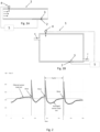
- Fig. 2 illustrates an example on sensor readouts affected by dosing of biocide according to a preferred embodiment of a method of dosing biocide into a fluid system.
- the figure illustrates a filtered sensor read-out, that is the raw electrical signal from the sensor filtered to remove noise in the signal.
- the figure also illustrates the filtered sensor read-out being averaged (the averaging method used will be disclosed below).
- a certain kind of periodicity is present and this is based on that the method operates in cycles where a cycle preferably extends between two subsequent dosing of biocide into the fluid system.
- three such dosing are indicates and the extend of a cycle is show by dotted lines.
- the measurements are recorded as data, typically in a form of data pairs comprising a measurement and the time it has been recorded e.g. as data structure: Y 1 Y 2 Y 3 Y n t 1 t 2 t 3 t n
- the method is preferably carried out on most recent measurements in order to track the evolution of biofilm formation.
- most recent measurements is typically meant that some collection may be used so as to e.g. carry out a sequence when a predefined time has passed.
- t 1 refers to the first measurement after beginning of a cycle, which may be the first usable measurement after beginning of a cycle.
- Fig. 3 illustrates an idealised sensor readout (by readout is meant that the curve presented is a smooth curve conceptual illustrating an actual sensor readout).
- the method according to the invention is based on that dosing is to be carried out when an inflection point IP is identified as occurring timewise after an identified minimum M (see fig. 3 ).
- the point in time of dosing is not indicated in fig. 3 , since fig. 3 is supposed to illustrate on a conceptual, various criteria that may be applied in the present invention.
- a sequence comprises the steps of:
- Step i) may comprise a two or three different actions, namely:
- step i) is implemented in a manner where a flag is set indicating that neither of a) or b) is to be executed.
- step a) is to be carried out irrespective of whether a minimum has already being identified. This is detailed even further below.
- the method operates in sequences. For instance, at some point in time a data set comprising measurements spanning say [t 1 ; t 100 ] does not contain neither a minimum M or an inflection point IP, and the sequence is repeated, when new data is(are) available. The sequence is repeated with such new data appended to data set a previous sequence carried on, whereby a subsequent sequence is carried out on e.g. measurements spanning [t 1 ; t 200 ]. This is repeated until an inflection point IP is identified as occurring time wise after a minimum M in the data set. When this has been identified, the method continues with carrying out a routine to determining a point in time for dosing.
- the method obtains a new data set by appending new available data, if any, to a previous data set, such as a current data set being the one most recently operated on, and execute steps i)-iii) above on the new data set until step iii) is fulfilled.
- Fig.3 schematically illustrates one way of identifying a minimum M and an inflection point IP.
- the disclosed way of identifying a minimum comprises evaluating the angle (or slope of angle) between two data points say Y n+1 and Y n .
- the slope changes sign when passing a minimum. In fig. 3 , this is disclosed as tan ⁇ ⁇ 0 before the minimum and tan ⁇ ⁇ 0 after a minimum.
- a minimum has been identified to be located between Y n+2 and Y n+1 .
- a time scale of the fouling can be determined, say the time spend after a dosing and before measurement asymptotic goes towards a constant value. Based on this, a time scale sufficient short to decompose the evolution of biofilm may be determined. For instance, in case the fouling constant is determined as 20 hours, a time scale can be selected as 5% of the fouling constant i.e. 1 hour.
- the time scale could be selected as correlated with sampling rate, e.g. if the sampling rate is 1 samples per minute, the time scale could be selected as 100 divided by 1 samples per minute, that is 100 minutes.
- sampling rate e.g. 1 samples per minute
- the time scale could be selected as 100 divided by 1 samples per minute, that is 100 minutes.
- the invention is not limited to such sampling rate.
- the value of the minimum M is used e.g. for evaluating the effect of the amount dosed and the numerical value of the minimum can be found in the data set by seeking up the lowest value between the data points where a minimum M is found.
- an inflection point IP can be determined when the rate of change in slope changes from increasing to decreasing.
- finite difference operators can be applied where for example an inflection point can been identified when: Y n + 1 ⁇ 2Y n + Y n ⁇ 1 / 0.5 * t n + 1 ⁇ t n ⁇ 1 changes sign. It is noted, that the denominator can be left out of the calculation, as the aim is to determine when a change in sign occurs.
- the method continues with determining an actual point in time for dosing.
- the method continues by recurrently obtaining a new data set by appending new available data, if any, to a current date set as disclosed above.
- the actual point in time for dosing can be predefined in a number of ways, and can be summarised as the point in time where the data set fulfils a predefined criteria. Various criteria are disclosed below.
- the dosing pump 4 is instructed to dose biocide and the dosing pump 4 biocide into the fluid system. That the pump is instructed to dose is based on an implementation where the pump has its own control system and a method according to the invention is implemented outside the pump's control system. If a method according to the invention is implemented in the control system of the pump, the pump's control system is programmed to dose when the criteria as outline herein is met.
- an ongoing cycle is defined to be completed either when the criteria for dosing is fulfilled or when dosing has been completed.
- the data set on which the sequences of a cycle has been carried out is preferably discarded in the sense that a new cycle does not contain measurement from a previous cycle.
- a new cycle executable similar or identical to the previous, is typically initiated. It is noted, that it is not mandatory for the invention, that a new cycle is initiated.
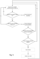
- Fig. 5 schematically illustrates the above preferred embodiment in context of a flow chart.
- the flow chart is initiated by appending new available measurement(s) to data set. Whether one or more measurements are appended is typically based on the time difference between two sequences and the sampling rate of the measurement from the sensor and can be selected as desired as long as the time difference is not so long that an inflection point cannot be captured before determining the point in time for dosing.
- the method looks for a minimum M. If a minimum is not identified, the method revert to the step of appending new measurement(s).
- measurements may contain what may be called a false minimum since it represents a local and not a global minimum.
- a sequence may be carried to include the step of identifying a minimum, and if a new minimum is identified then replacing a previous identified minimum with the newly identified. Such a replacement is in some preferred embodiment be carried out under the provision that the newly found minimum has a smaller value than the previous.
- a minimum is identified, this is recorded. If a minimum is identified, the method continues with identifying an inflection point IP, and if identified, this is recorded. If not, the method goes back to the initial step. If inflection point IP is identified, the method checks whether the inflection point IP occurs timewise after an identified minimum M. If not, the method goes back to the initial step. If yes, the method proceed towards dosing. When dosing is completed, a new cycle is to be carried out.
- dosing is to be carried out after a global inflection point IP has been identified timewise after a global minimum M within a cycle.
- the value of the measurement goes asymptotic towards a constant value, which can be referred to as a plateau.
- This plateau represents that the formation of biofilm goes towards a situation where the sensor is no longer capable of measuring a further growth.
- This can be referred to as the sensor readout has reached a steady state where the signal may no longer increase, although the biofilm formation may continue. It is therefore often preferred to dose before such a plateau is reached.
- a characterizing feature of the data after the inflection point is that the slope or an angle corresponding to the slope decreases and this can be used to determine when to dose.
- the number of sequences further includes a step of determining a slope or an angle corresponding to the slope in the data set time wise after the occurrence of the inflection point (IP).
- IP inflection point
- the point in time to initiate dosing of biocide is then based changes in the determined slopes.
- the angle corresponding to the slope is determined directly or derived from the slope.
- the angle may be determined by evaluating arc tan (slope).
- ⁇ t is the time difference between the two data point.
- the slope calculated in this manner is a first order approximation to slope the curve of data points midway between the two data point.
- the straight line defines an angle ⁇ with respect to the time axis. Accordingly, this angle is said to be the angle corresponding to the slope.
- dosing is pre-selected to occur when the plateau has emerged. This would require that the slope or the angle corresponding to the slope is determined to be zero or close to zero, and this may take long time to reach this target, during which other parts of the system may experience undesirable high rate of biofilm formation.
- the actual value of the predefined threshold may be found by experiments, although good candidates for the threshold for the slope have been found in connection with the present invention to be between tangents of angles 10 to 30 .
- Another candidate may be a tangents of angles less than tangent of 40 degrees.
- dosing is selected as to be carried out close to the plateau.
- This has inter alia the advantage that dosing is done close to the point in time where the sensor is no longer capable of measuring a further growth, whereby dosing may be carried out most cost effective compared to a situation where dosing is repeatedly done in consecutive cycles earlier than close to the plateau.
- this may be implemented by examining the evolution of the angle corresponding to slope after the inflection point IP and implementing that the dosing criteria to be fulfilled includes that the angle of the slope pass a predefined threshold.
- the actual value of the threshold may be determined based on experiments, although good candidates for the threshold for the angle corresponding to the slope have been found in connection with the present invention to be between, between tangents of ( ⁇ , ⁇ ) 30 and 40 degrees. Another good candidate could be selected between greater than 40 and less than 60 degrees.
- one aim dosing close to a point in time after the inflection point IP. Since the biofilm sensor, at least presumable, mirrors the state of the fluid system, the aim can be seen as a measure to avoid larger build-up of biofilm in the fluid system.
- the dosing criteria to be fulfilled may include that the angle corresponding to the slope pass a predefined threshold.
- the actual value of the threshold may be determined based on experiments, although good candidates for the threshold for the angle corresponding to the slope have been found in connection with the present invention to be between, between tangents of ( ⁇ , ⁇ ) 50 and 70 degrees. Other good candidates could be selected between more than 70 and less than 90 degrees.
- the point in time for dosing is determined by fitting a linear line to a subset of data.
- the subset of data is data selected to be data after step iii) above, that is after and inflection point IP has been identified as occurring after a minimum M.
- the procedure which is schematically illustrated in fig. 4 , includes the determination of a correlation coefficient between the linear line and the data of the data set.
- two such linear lines L 1 and L 2 are shown. The first one L 1 is shown to have a correlation coefficient R around 1 with the data to which it is fitted and the other one L 2 is shown to have a correlation coefficient slightly larger than 0.95.
- this behaviour in the data is used to initiate dosing of biocide at the point in time where the correlation coefficient becomes larger than a preselected number, such as larger than 0.9, preferably larger than 0.95, such as larger than 0.99.
- a preselected number such as larger than 0.9, preferably larger than 0.95, such as larger than 0.99.
- the correlation coefficient after the inflection point IP may decrease and at some point after in time the decrease and at some point in time changes into increase.
- it may be necessary to impose a further criteria to avoid dosing immediately after and inflection point since immediately after the inflection point the correlation coefficient may be e.g. larger than the preselected number.
- the reference magnitude Z is preferable defined relatively to a baseline BL (see fig. 3 and 4 ).
- This baseline could take the value of the global minimum M, if identified. Otherwise, the minimum value found in the measurements can be used as value for the baseline BL.
- the actual value of the reference magnitude Z is typically a fixed and predefined value typically depending the sensor type used. The determination of Z can be made by experiments. As illustrated in fig. 3 , one way of implementing this further requirement includes evaluation of the following equation: Y 6 ⁇ Y 2 + Y 3 2 > Z
- Another advantage of preferred embodiments of methods according to the invention is its possibility of tracking the effect of dosing in different, typically consecutive, cycles. It has been found in connection with the present invention that the value of the global minima in a cycle is the result of the actual dosing at the beginning of the cycle, such as the amount of biocide dosed. It has been found that when the value of the global minimum in a cycle increases from cycle to cycle, the amount dosed is not enough to remove the biofilm on the biofilm sensor 3.
- Lower part of fig. 7 illustrates a scenario in which the global minima are decreasing between consecutive cycles. The experiment is conducted with an increasing dosis between cycles.
- the method further comprising recording for a number of subsequently identified global minima M's, for each of which a global inflection point (IP) has been identified time wise after, the magnitudes of the minima. Also in this case, The number of subsequently identified global minima could be three, four, five, six or even more.
- IP global inflection point
- the number of subsequently identified global minima could be three, four, five, six or even more.
- preferred embodiments of the method may further comprise recording for a number of subsequently identified global minima M's, for each of which an inflection point IP has been identified time wise after, the magnitude of the global minima.
- the method determines whether the magnitude of the global minima are essentially constant over time, and if the magnitudes are essentially constant over time, the method decrease the amount of biocide dosed into the fluid system in one or more subsequent dosing.
- dosing regulations (increase, decrease or maintain current dosis) is found to be dependent of the actual layout of the fluid system as well e.g. the contents of nutrients in fluid, oxygen level and/or temperature.
- default values are predefined, e.g. if dosing is to be increased, the dosing is increased by 30% and if dosing is to be decreased the dosing is decreased by 10%.
- empiricism is gradually obtained for the system which can be used to refine the dosing regulations e.g. by scaling the default regulations depending on changes identified in a number of consecutive global minima.
- empirical relations are known a priory, e.g. from similar or identical fluid systems, and such empirical relation can be implemented in a newly set-up system.
- dosing could be controlled by a machine learning algorithm
- the way of determining the increase or decrease in magnitudes of the global minima can be determined in a number of way.
- the slope of such a fitted straight line can at least indicate whether the minima are increasing (positive slope) or decreasing (negative slope).
- the correlation coefficient for the fitted line to the global minima is considered.
- it is required that the correlation coefficient is larger or lower than predefined number, such as larger than 0.9 or lower than -0.9 before the slope of this fitted line is used to determine whether the minima are increasing or decreasing.
- the fitted straight line preferably takes as variable, counts of minima (1, 2, 3, ..n) and the values of the minima. In terms of data pairs this may be visualised as M 1 M 2 M 3 M n n 1 n 2 n 3 n n
- the raw readout from the biofilm sensor 3 is typically a continuous electrical signal.
- a signal or a signal in general from a biofilm sensor, is preferably filtered, e.g. to remove noise from the signal.
- a sampling is preferably used to provide discrete signals. The sampling rate is selected so assure that data is representative for the measurements.
- a time stamp is preferably provided to each data so that data pairs containing magnitude and the time the magnitude occurs is logged.
- the invention may make use of applying a moving mean algorithm having a predefined window size on the filtered read-outs. In embodiments not including filtering, the moving mean may still be applied according to the invention.
- FIG. 6 An example of a moving mean algorithm used in preferred embodiments of the invention is sketched in fig. 6 .
- fig. 6 three tables are shown labelled with “ i ", " ii “ and “ iii “ respectively.
- Each table shown has a counter [1....] for the consecutive counts of measurements y .
- the value resulting from applying the moving mean is indicated as y ⁇ ..
- the data points on which the moving mean is based is shown as subscript"[..]".
- subscript 1 when the first data point is available (subscript 1) that very data point is assigned to be representative of the moving mean at the point in time where only this data point is available.
- subscript 2 when further data points are available the data points available is used in determining the moving mean.
- a window size of twenty measurement is used when determining the moving mean, although the invention is not limited to this actual window size.
- the data points used at a given time (after twenty data points are available) can symbolic be written as: y ⁇ n ⁇ windsow size + 1 n
- n in this symbolic writing is the n th data point and " window size " is an integer. In the above example the window size is twenty.
- the determinations of the minimum M, inflection point IP and other characteristics of the curve of measurement is based on measurement to which such a moving average is applied.
- a minimum M is identified as a change in slope from smaller than zero to larger than zero (see fig. 3 and description above) or identified as the slope being equal to zero.
- the angle corresponding to the slope can be evaluated based on the angle corresponding to the slope, typically evaluated as tan(slope), where a change in sign show the presence of a minimum.
- Alternative methods to determine a minimum and an IP can be non parametric fitting techniques (e.g. smoothing splines, locally weighted scatter smoothing) and machine learning cycle shape recognition.
- an inflection point IP is in preferred embodiment the position where a rate of change in slope or the angle corresponding to the slope is from increasing to decreasing.
- Preferred embodiments of the invention are executed in a manner than can be termed on-line mode.
- the method is essentially carried out synchronized with the occurrence of data, such that a sequence is based on a data set comprising most recent available data.
- a sequence is based on a data set comprising most recent available data.
- delays in data transmission and other delays is in-essential.
- the invention may also be carried out in what may be called off-line mode.
- a number of data points are collected before the procedure for identifying minimum M, inflection point IP and other characteristics of the measurements is carried out.
- This may have the advantage that a spline or other curve fitting can be overlaid the measurements, which potentially may reduce the risk of identifying local and not global minimum M and/or inflection point.
- the invention also relates to an hardware implementation of the various embodiments of the method according to the invention.
- the hardware implementation relates to a fluid system 1 comprising a biofilm sensor 2 arranged in the fluid system 1.
- the biofilm sensor 2 is arranges so that its sensing surface 3 is exposed to a fluid in the fluid system (when fluid is present in the system).
- the biofilm sensor 2 is configured to measure an amount of biofilm on said sensing surface 3 of the biofilm sensor 2.
- the biofilm sensor is preferably of an electro-chemical sensor type readily available for purchase.
- a dosing pump 4 is arranged in the fluid system 1 to dose biocide into fluid system. Further, a control unit 5 configured for carrying out embodiments of the method according to invention is equipped and configured to activating the dosing device.
- a preferred embodiment of the method is installed a dosing pump 4.
- Such dosing pumps typically has an electronic controller including a memory used inter alia to store measurements data, such as an PLC controller for controlling the operation of the pump.
- an electronic controller is software based, preferred embodiments of the invention can be implemented in such a controller by downloading software which when executed carries out method steps according to a preferred embodiment of the invention.
- the electronic controller typically has an interface which can be used to receive sensor read-outs from the biofilm sensor 2.
- the invention can be implemented by means of hardware, software, firmware or any combination of these.
- the invention or some of the features thereof can also be implemented as software running on one or more data processors and/or digital signal processors.
- the individual elements of an embodiment of the invention may be physically, functionally and logically implemented in any suitable way such as in a single unit, in a plurality of units or as part of separate functional units.
- the invention may be implemented in a single unit, or be both physically and functionally distributed between different units and processors.
Landscapes
- Engineering & Computer Science (AREA)
- Life Sciences & Earth Sciences (AREA)
- Physics & Mathematics (AREA)
- Health & Medical Sciences (AREA)
- Theoretical Computer Science (AREA)
- Environmental & Geological Engineering (AREA)
- Hydrology & Water Resources (AREA)
- Water Supply & Treatment (AREA)
- Organic Chemistry (AREA)
- Chemical & Material Sciences (AREA)
- Bioinformatics & Cheminformatics (AREA)
- Medical Informatics (AREA)
- Spectroscopy & Molecular Physics (AREA)
- Biotechnology (AREA)
- Evolutionary Biology (AREA)
- Evolutionary Computation (AREA)
- General Health & Medical Sciences (AREA)
- Bioinformatics & Computational Biology (AREA)
- General Physics & Mathematics (AREA)
- Biophysics (AREA)
- Computer Hardware Design (AREA)
- Pure & Applied Mathematics (AREA)
- Databases & Information Systems (AREA)
- Epidemiology (AREA)
- Computer Vision & Pattern Recognition (AREA)
- Public Health (AREA)
- Software Systems (AREA)
- Bioethics (AREA)
- Artificial Intelligence (AREA)
- General Engineering & Computer Science (AREA)
- Geometry (AREA)
- Data Mining & Analysis (AREA)
- Mathematical Physics (AREA)
- Molecular Biology (AREA)
- Physiology (AREA)
- Mathematical Optimization (AREA)
- Mathematical Analysis (AREA)
- Fluid Mechanics (AREA)
- Computing Systems (AREA)
- Algebra (AREA)
Claims (17)
- Verfahren zur Dosierung von Biozid in ein Fluidsystem (1), wobei das Verfahren nach einer, beispielsweise zwischen zwei aufeinanderfolgenden, Dosierungen von Biozid in das Fluidsystem durchgeführt wird, wobei das Fluidsystem umfasst• einen Biofilmsensor (2), der in dem Fluidsystem (1) angeordnet ist und eine Sensorfläche (3) aufweist, die einem Strömungsfluid in dem Fluidsystem ausgesetzt ist, wobei der Sensor, wenn Fluid in dem System vorhanden ist, so konfiguriert ist, dass er eine Menge an Biofilm auf der Sensorfläche (3) des Biofilmsensors (2) misst,• eine Dosierpumpe (4), die in dem Fluidsystem (1) angeordnet ist, um Biozid in das Fluidsystem zu dosieren,
wobei das Verfahren in einer Anzahl von Sequenzen auf der Basis von Datensätzen durchgeführt wird, die durch den Biofilmsensor (2) erhaltene Messungen der Menge an Biofilm nach einer letzten Dosierung von Biozid darstellen, wobei die Sequenz die Schritte umfasst von:i) Identifizieren, falls vorhanden, eines Minimums (M) in dem Datensatz und, falls identifiziert, Aufzeichnen, dass ein Minimum (M) identifiziert wurde,ii) Identifizieren, falls vorhanden, eines Wendepunkts (IP) in dem Datensatz und, falls identifiziert, Aufzeichnen, dass ein Wendepunkt identifiziert wurde,iii) wenn ein Wendepunkt (IP) identifiziert wurde, der zeitlich nach einem identifizierten Minimum (M) auftritt, Bestimmen eines Zeitpunkts für die Dosierung von Biozid in das Fluidsystem (1) durch die Verwendung der Dosierpumpe (4);• wenn ein Wendepunkt (IP), der zeitlich nach einem identifizierten Minimum (M) auftritt, nicht identifiziert wurde, Erhalten eines neuen Datensatzes durch Anhängen neuer verfügbarer Daten, falls vorhanden, an den Datensatz und Ausführen der Schritte i) - iii) an dem neuen Datensatz, bis Schritt iii) erfüllt ist,
wobei• der Zeitpunkt für die Dosierung durch wiederholtes Erhalten eines neuen Datensatzes durch Anhängen neuer verfügbarer Daten, falls vorhanden, an einen aktuellen Datensatz und Bestimmen des Zeitpunkts, an dem der Datensatz ein vordefiniertes Dosierungskriterium erfüllt, bestimmt wird,
und wobei das Verfahren weiter umfasst• Dosieren von Biozid in das Fluidsystem unter Verwendung der Dosierpumpe (4), wenn das vordefinierte Kriterium erfüllt ist. - Verfahren nach Anspruch 1, wobei die Anzahl der Sequenzen weiter das Bestimmen einer Steigung oder eines der Steigung entsprechenden Winkels in dem Datensatz zeitlich nach dem Auftreten des Wendepunkts (IP) und das Bestimmen des Zeitpunkts zum Einleiten der Dosierung von Biozid auf der Grundlage von Änderungen der bestimmten Steigungen oder des der Steigung entsprechenden Winkels umfasst.
- Verfahren nach 2, wobei das zu erfüllende Dosierungskriterium umfasst, dass der der Steigung entsprechende Winkel einen vordefinierten Schwellenwert überschreitet, der vorzugsweise zwischen dem Tangens von Winkeln von 10-30 Grad oder dem Tangens von Winkeln von vorzugsweise weniger als 40 Grad ausgewählt wird.
- Verfahren nach 2, wobei das zu erfüllende Dosierungskriterium umfasst, dass der der Steigung entsprechende Winkel einen vordefinierten Schwellenwert überschreitet, der vorzugsweise zwischen dem Tangens von Winkeln (γ, λ) zwischen 30 und 40 Grad oder vorzugsweise größer als 40 und kleiner als 60 ausgewählt wird.
- Verfahren nach 2, wobei das zu erfüllende Dosierungskriterium umfasst, dass der der Steigung entsprechende Winkel einen vordefinierten Schwellenwert überschreitet, der vorzugsweise zwischen den Tangens von Winkeln (ϕ, ψ) 50 und 70 Grad oder vorzugsweise mehr als 70 und weniger als 90 Grad ausgewählt wird.
- Verfahren nach einem der vorstehenden Ansprüche, wobei die Anzahl der Sequenzen weiter das Anpassen einer linearen Linie an einen Teilsatz von Daten nach Schritt iii), das Bestimmen eines Korrelationskoeffizienten zwischen der linearen Linie und den Daten des Datensatzes und das Bestimmen des Zeitpunkts für die Einleitung der Dosierung von Biozid zu dem Zeitpunkt umfasst, an dem der Korrelationskoeffizient größer als eine vorausgewählte Zahl wird, wie beispielsweise größer als 0,9, vorzugsweise größer als 0,95, wie beispielsweise größer als 0,99.
- Verfahren nach einem der vorstehenden Ansprüche, wobei das zu erfüllende Dosierungskriterium weiter umfasst, dass die Größe der Daten, die die Messungen der Menge an Biofilm darstellen, über einer vordefinierten Referenzgröße (Z) liegt.
- Verfahren nach einem der vorstehenden Ansprüche, wobei das Verfahren weiter umfasst• Aufzeichnen der Größe der Minima für eine Anzahl von nachfolgend identifizierten Minima (M's), für die jeweils ein Wendepunkt (IP) zeitlich danach identifiziert wurde,• Bestimmen, ob die Größen der Minima im Laufe der Zeit zunehmen, und• wenn die Größen im Laufe der Zeit zunehmen, Erhöhen der Menge des in das Fluidsystem dosierten Biozids in einer oder mehreren nachfolgenden Dosierungen.
- Verfahren nach einem der vorstehenden Ansprüche, wobei das Verfahren weiter umfasst• Aufzeichnen der Größe der Minima für eine Anzahl von nachfolgend identifizierten Minima (M's), für die jeweils ein Wendepunkt (IP) zeitlich danach identifiziert wurde,• Bestimmen, ob die Größen der Minima im Laufe der Zeit abnehmen, und• wenn die Größen im Laufe der Zeit abnehmen, Beibehalten einer aktuellen Menge an Biozid, die in das Fluidsystem dosiert wird, in einer oder mehreren nachfolgenden Dosierungen.
- Verfahren nach einem der vorstehenden Ansprüche, wobei das Verfahren weiter umfasst• Aufzeichnen der Größe der Minima für eine Anzahl von nachfolgend identifizierten Minima (M's), für die jeweils ein Wendepunkt (IP) zeitlich danach identifiziert wurde,• Bestimmen, ob die Größen der Minima über die Zeit im Wesentlichen konstant sind, und• wenn die Größen über die Zeit im Wesentlichen konstant sind, Verringern der Menge des in das Fluidsystem dosierten Biozids in einer oder mehreren nachfolgenden Dosierungen.
- Verfahren nach Anspruch 8 oder 9, wobei die Erhöhung oder Verringerung der Größe der Minima (M's) auf der Grundlage der Anpassung einer geraden Linie durch die betrachteten Minima bestimmt wird und, wenn der Korrelationskoeffizient größer als eine vordefinierte Zahl, beispielsweise größer als 0,9, ist, die Steigung dieser angepassten Linie verwendet wird, um zu bestimmen, ob die Minima abnehmen oder zunehmen, wobei die angepasste gerade Linie vorzugsweise als Variable die Anzahl der Minima (1, 2, 3, ..n) und die Werte der Minima nimmt.
- Verfahren nach einem der vorstehenden Ansprüche, wobei der Datensatz, der Messungen der Menge an Biofilm darstellt, durch Filtern von Messwertausgaben des Sensors und Anwenden eines Algorithmus für den gleitenden Mittelwert mit einer vordefinierten Fenstergröße auf die gefilterten Messwertausgaben erhalten wird, wobei die Fenstergröße eine ganze Zahl ist, die einer Anzahl von aufeinanderfolgenden Datenpunkten entspricht.
- Verfahren nach einem der vorstehenden Ansprüche, wobei ein Minimum (M) als eine Änderung der Steigung von kleiner als Null zu größer als Null identifiziert wird, die Steigung Null ist oder der der Steigung entsprechende Winkel das Vorzeichen von negativ zu positiv ändert.
- Verfahren nach einem der vorstehenden Ansprüche, wobei ein Wendepunkt (IP) als eine Änderungsrate der Steigung oder des der Steigung entsprechenden Winkels von zunehmend zu abnehmend bestimmt wird.
- Verfahren nach einem der vorstehenden Ansprüche, wobei das Verfahren im Wesentlichen synchronisiert mit dem Auftreten von Daten durchgeführt wird, so dass eine Sequenz auf einem Datensatz basiert, der die letzten verfügbaren Daten umfasst.
- Fluidsystem (1), das einen in dem Fluidsystem (1) angeordneten Biofilmsensor (2) umfasst und eine Sensorfläche (3) aufweist, die einem Fluid in dem Fluidsystem ausgesetzt ist, wobei der Sensor so konfiguriert ist, dass er eine Menge an Biofilm auf der Sensorfläche (3) des Biofilmsensors (2) misst, eine Dosierpumpe (4), die in dem Fluidsystem (1) angeordnet ist, um Biozid in das Fluidsystem zu dosieren, und eine Steuereinheit (5), die so konfiguriert ist, dass sie Sensormesswertausgaben von dem Biofilmsensor (2) empfängt, die Sensormesswertausgaben verarbeitet und die Dosierpumpe (4) aktiviert, um das Verfahren nach einem der vorstehenden Ansprüche durchzuführen.
- Dosierpumpe (4), die eine elektronische Steuereinheit (5), wie beispielsweise eine SPS-Steuerung, umfasst, wobei die Steuereinheit (5) so konfiguriert ist, dass sie Sensormesswertausgaben von einem Biofilmsensor (2) empfängt, der eine Sensorfläche (3) aufweist und der in einem Fluidsystem (1) angeordnet ist, und eine Menge an Biofilm auf der Sensorfläche (3) misst, wobei die Steuereinheit (5) weiter so konfiguriert ist, dass sie die Sensormesswertausgaben verarbeitet und die Dosierpumpe (4) aktiviert, wenn sie in dem Fluidsystem (1) angeordnet ist, um das Biozid in dem Fluidsystem (1) gemäß dem Verfahren nach einem der vorstehenden Ansprüche 1 - 15 zu dosieren.
Priority Applications (3)
| Application Number | Priority Date | Filing Date | Title |
|---|---|---|---|
| EP20215430.8A EP4014736B1 (de) | 2020-12-18 | 2020-12-18 | Verfahren zur dosierung eines biozids in ein fluidsystem |
| US17/552,442 US20220194826A1 (en) | 2020-12-18 | 2021-12-16 | Method of dosing biocide into a fluid system |
| CN202111563709.9A CN114649057A (zh) | 2020-12-18 | 2021-12-20 | 对进入流体系统的生物杀灭剂计量的方法 |
Applications Claiming Priority (1)
| Application Number | Priority Date | Filing Date | Title |
|---|---|---|---|
| EP20215430.8A EP4014736B1 (de) | 2020-12-18 | 2020-12-18 | Verfahren zur dosierung eines biozids in ein fluidsystem |
Publications (3)
| Publication Number | Publication Date |
|---|---|
| EP4014736A1 EP4014736A1 (de) | 2022-06-22 |
| EP4014736C0 EP4014736C0 (de) | 2024-11-27 |
| EP4014736B1 true EP4014736B1 (de) | 2024-11-27 |
Family
ID=73855763
Family Applications (1)
| Application Number | Title | Priority Date | Filing Date |
|---|---|---|---|
| EP20215430.8A Active EP4014736B1 (de) | 2020-12-18 | 2020-12-18 | Verfahren zur dosierung eines biozids in ein fluidsystem |
Country Status (3)
| Country | Link |
|---|---|
| US (1) | US20220194826A1 (de) |
| EP (1) | EP4014736B1 (de) |
| CN (1) | CN114649057A (de) |
Family Cites Families (6)
| Publication number | Priority date | Publication date | Assignee | Title |
|---|---|---|---|---|
| US9886945B1 (en) * | 2011-07-03 | 2018-02-06 | Reality Analytics, Inc. | System and method for taxonomically distinguishing sample data captured from biota sources |
| DE102011080956A1 (de) * | 2011-07-25 | 2013-01-31 | Endress + Hauser Conducta Gesellschaft für Mess- und Regeltechnik mbH + Co. KG | Verfahren und Messstelle zur Messung zumindest einer physikalischen und/oder chemischen Prozessgrößen eines in einem Einwegbehältnis enthaltenen Messmediums |
| DK3298101T3 (da) * | 2015-05-19 | 2020-01-06 | Total Sa | Vandindsprøjtningssystem omfattende biofilmsensor(er) |
| EP3470378B1 (de) * | 2017-10-13 | 2023-06-07 | Grundfos Holding A/S | Dosierpumpe und verfahren zur dosierung von antiscalant in ein membranbasiertes wasserbehandlungssystem |
| CN109504783B (zh) * | 2018-12-06 | 2022-04-08 | 青岛海关技术中心 | 贻贝GST μ亚型基因在检测溴氰菊酯污染的水产品的应用 |
| GB2581217B (en) * | 2019-05-10 | 2021-03-17 | Solmicrotek Ltd | Biofilm sensor |
-
2020
- 2020-12-18 EP EP20215430.8A patent/EP4014736B1/de active Active
-
2021
- 2021-12-16 US US17/552,442 patent/US20220194826A1/en active Pending
- 2021-12-20 CN CN202111563709.9A patent/CN114649057A/zh active Pending
Also Published As
| Publication number | Publication date |
|---|---|
| US20220194826A1 (en) | 2022-06-23 |
| EP4014736C0 (de) | 2024-11-27 |
| EP4014736A1 (de) | 2022-06-22 |
| CN114649057A (zh) | 2022-06-21 |
Similar Documents
| Publication | Publication Date | Title |
|---|---|---|
| JP7344201B2 (ja) | 冷却水監視制御システム | |
| AU2016253191B2 (en) | Method and apparatus for assessing a state of fouling of a reverse osmosis system | |
| US11662314B2 (en) | System and method of inline deposit detection in process fluid | |
| CN118145765B (zh) | 基于膜壳利用变频电磁场杀菌阻垢监测方法及系统 | |
| SG184913A1 (en) | A method and system for optimizing membrane cleaning process | |
| CN118253059B (zh) | 基于物联网的消防水池远程监测方法 | |
| Hijnen et al. | Threshold concentration of easily assimilable organic carbon in feedwater for biofouling of spiral-wound membranes | |
| JP2013215698A (ja) | 水処理プラントの状態診断方法及び装置 | |
| JP4426113B2 (ja) | 生物付着モニターおよび生物付着をモニターまたは検出する方法 | |
| EP4014736B1 (de) | Verfahren zur dosierung eines biozids in ein fluidsystem | |
| WO2019059310A1 (ja) | 情報処理装置 | |
| Zondervan et al. | Development of a dynamic model for cleaning ultra filtration membranes fouled by surface water | |
| JP2009095742A (ja) | スライム防止方法およびハロゲン系殺菌剤添加システム | |
| CN115676935B (zh) | 一种基于纳米水处理技术的河道净化处理方法 | |
| WO2013129111A1 (ja) | 造水方法 | |
| KR20260009300A (ko) | 필터 상태를 결정하기 위한 시스템 | |
| CN116323961A (zh) | 用于运行处理设备的方法以及处理设备 | |
| JP2016190212A (ja) | 分離膜ろ過プラントにおける分離膜の酸化リスク評価方法 | |
| Pratofiorito et al. | Application of online biofilm sensors for membrane performance assessment in high organic load reverse osmosis feed streams | |
| Jun et al. | Optimizing Air Scouring Energy for Sustainable Membrane Bioreactor Operation by Characterizing the Combination of Factors Leading to Threshold Limiting Conditions | |
| US5285162A (en) | Galvanic current measuring method and apparatus for monitoring build-up of biological deposits on surfaces of dissimilar metal electrodes immersed in water | |
| KR20170101936A (ko) | 탈기된 액체 내로 광학 투과율을 얻거나 유지하는 방법 | |
| Alvarez-Arroyo et al. | Evaluation of drinking water quality produced by ultrafiltration membranes in distribution systems | |
| WO2024185651A1 (en) | Control device, control method, and control program | |
| EP3089947B1 (de) | Anordnung und verfahren zur steuerung der bildung von ablagerungen |
Legal Events
| Date | Code | Title | Description |
|---|---|---|---|
| PUAI | Public reference made under article 153(3) epc to a published international application that has entered the european phase |
Free format text: ORIGINAL CODE: 0009012 |
|
| STAA | Information on the status of an ep patent application or granted ep patent |
Free format text: STATUS: THE APPLICATION HAS BEEN PUBLISHED |
|
| AK | Designated contracting states |
Kind code of ref document: A1 Designated state(s): AL AT BE BG CH CY CZ DE DK EE ES FI FR GB GR HR HU IE IS IT LI LT LU LV MC MK MT NL NO PL PT RO RS SE SI SK SM TR |
|
| STAA | Information on the status of an ep patent application or granted ep patent |
Free format text: STATUS: REQUEST FOR EXAMINATION WAS MADE |
|
| 17P | Request for examination filed |
Effective date: 20221221 |
|
| RBV | Designated contracting states (corrected) |
Designated state(s): AL AT BE BG CH CY CZ DE DK EE ES FI FR GB GR HR HU IE IS IT LI LT LU LV MC MK MT NL NO PL PT RO RS SE SI SK SM TR |
|
| STAA | Information on the status of an ep patent application or granted ep patent |
Free format text: STATUS: EXAMINATION IS IN PROGRESS |
|
| 17Q | First examination report despatched |
Effective date: 20231124 |
|
| GRAP | Despatch of communication of intention to grant a patent |
Free format text: ORIGINAL CODE: EPIDOSNIGR1 |
|
| STAA | Information on the status of an ep patent application or granted ep patent |
Free format text: STATUS: GRANT OF PATENT IS INTENDED |
|
| RIC1 | Information provided on ipc code assigned before grant |
Ipc: C02F 1/72 20060101ALN20240521BHEP Ipc: G01N 33/483 20060101ALI20240521BHEP Ipc: C02F 1/50 20060101ALI20240521BHEP Ipc: C02F 1/00 20060101ALI20240521BHEP Ipc: A61L 2/24 20060101ALI20240521BHEP Ipc: A01N 25/00 20060101AFI20240521BHEP |
|
| RIC1 | Information provided on ipc code assigned before grant |
Ipc: C02F 1/72 20060101ALN20240613BHEP Ipc: G01N 33/483 20060101ALI20240613BHEP Ipc: C02F 1/50 20060101ALI20240613BHEP Ipc: C02F 1/00 20060101ALI20240613BHEP Ipc: A61L 2/24 20060101ALI20240613BHEP Ipc: A01N 25/00 20060101AFI20240613BHEP |
|
| INTG | Intention to grant announced |
Effective date: 20240625 |
|
| GRAS | Grant fee paid |
Free format text: ORIGINAL CODE: EPIDOSNIGR3 |
|
| GRAA | (expected) grant |
Free format text: ORIGINAL CODE: 0009210 |
|
| STAA | Information on the status of an ep patent application or granted ep patent |
Free format text: STATUS: THE PATENT HAS BEEN GRANTED |
|
| AK | Designated contracting states |
Kind code of ref document: B1 Designated state(s): AL AT BE BG CH CY CZ DE DK EE ES FI FR GB GR HR HU IE IS IT LI LT LU LV MC MK MT NL NO PL PT RO RS SE SI SK SM TR |
|
| REG | Reference to a national code |
Ref country code: GB Ref legal event code: FG4D |
|
| REG | Reference to a national code |
Ref country code: CH Ref legal event code: EP |
|
| REG | Reference to a national code |
Ref country code: DE Ref legal event code: R096 Ref document number: 602020041983 Country of ref document: DE |
|
| REG | Reference to a national code |
Ref country code: IE Ref legal event code: FG4D |
|
| U01 | Request for unitary effect filed |
Effective date: 20241218 |
|
| U07 | Unitary effect registered |
Designated state(s): AT BE BG DE DK EE FI FR IT LT LU LV MT NL PT RO SE SI Effective date: 20250108 |
|
| U20 | Renewal fee for the european patent with unitary effect paid |
Year of fee payment: 5 Effective date: 20241230 |
|
| PG25 | Lapsed in a contracting state [announced via postgrant information from national office to epo] |
Ref country code: HR Free format text: LAPSE BECAUSE OF FAILURE TO SUBMIT A TRANSLATION OF THE DESCRIPTION OR TO PAY THE FEE WITHIN THE PRESCRIBED TIME-LIMIT Effective date: 20241127 Ref country code: IS Free format text: LAPSE BECAUSE OF FAILURE TO SUBMIT A TRANSLATION OF THE DESCRIPTION OR TO PAY THE FEE WITHIN THE PRESCRIBED TIME-LIMIT Effective date: 20250327 |
|
| PG25 | Lapsed in a contracting state [announced via postgrant information from national office to epo] |
Ref country code: ES Free format text: LAPSE BECAUSE OF FAILURE TO SUBMIT A TRANSLATION OF THE DESCRIPTION OR TO PAY THE FEE WITHIN THE PRESCRIBED TIME-LIMIT Effective date: 20241127 |
|
| PG25 | Lapsed in a contracting state [announced via postgrant information from national office to epo] |
Ref country code: NO Free format text: LAPSE BECAUSE OF FAILURE TO SUBMIT A TRANSLATION OF THE DESCRIPTION OR TO PAY THE FEE WITHIN THE PRESCRIBED TIME-LIMIT Effective date: 20250227 |
|
| PG25 | Lapsed in a contracting state [announced via postgrant information from national office to epo] |
Ref country code: GR Free format text: LAPSE BECAUSE OF FAILURE TO SUBMIT A TRANSLATION OF THE DESCRIPTION OR TO PAY THE FEE WITHIN THE PRESCRIBED TIME-LIMIT Effective date: 20250228 |
|
| PG25 | Lapsed in a contracting state [announced via postgrant information from national office to epo] |
Ref country code: PL Free format text: LAPSE BECAUSE OF FAILURE TO SUBMIT A TRANSLATION OF THE DESCRIPTION OR TO PAY THE FEE WITHIN THE PRESCRIBED TIME-LIMIT Effective date: 20241127 |
|
| PG25 | Lapsed in a contracting state [announced via postgrant information from national office to epo] |
Ref country code: RS Free format text: LAPSE BECAUSE OF FAILURE TO SUBMIT A TRANSLATION OF THE DESCRIPTION OR TO PAY THE FEE WITHIN THE PRESCRIBED TIME-LIMIT Effective date: 20250227 |
|
| PG25 | Lapsed in a contracting state [announced via postgrant information from national office to epo] |
Ref country code: SM Free format text: LAPSE BECAUSE OF FAILURE TO SUBMIT A TRANSLATION OF THE DESCRIPTION OR TO PAY THE FEE WITHIN THE PRESCRIBED TIME-LIMIT Effective date: 20241127 |
|
| PG25 | Lapsed in a contracting state [announced via postgrant information from national office to epo] |
Ref country code: SK Free format text: LAPSE BECAUSE OF FAILURE TO SUBMIT A TRANSLATION OF THE DESCRIPTION OR TO PAY THE FEE WITHIN THE PRESCRIBED TIME-LIMIT Effective date: 20241127 |
|
| PG25 | Lapsed in a contracting state [announced via postgrant information from national office to epo] |
Ref country code: CZ Free format text: LAPSE BECAUSE OF FAILURE TO SUBMIT A TRANSLATION OF THE DESCRIPTION OR TO PAY THE FEE WITHIN THE PRESCRIBED TIME-LIMIT Effective date: 20241127 |
|
| REG | Reference to a national code |
Ref country code: CH Ref legal event code: PL |
|
| PG25 | Lapsed in a contracting state [announced via postgrant information from national office to epo] |
Ref country code: MC Free format text: LAPSE BECAUSE OF FAILURE TO SUBMIT A TRANSLATION OF THE DESCRIPTION OR TO PAY THE FEE WITHIN THE PRESCRIBED TIME-LIMIT Effective date: 20241127 |
|
| PLBE | No opposition filed within time limit |
Free format text: ORIGINAL CODE: 0009261 |
|
| STAA | Information on the status of an ep patent application or granted ep patent |
Free format text: STATUS: NO OPPOSITION FILED WITHIN TIME LIMIT |
|
| PG25 | Lapsed in a contracting state [announced via postgrant information from national office to epo] |
Ref country code: CH Free format text: LAPSE BECAUSE OF NON-PAYMENT OF DUE FEES Effective date: 20241231 |
|
| PG25 | Lapsed in a contracting state [announced via postgrant information from national office to epo] |
Ref country code: IE Free format text: LAPSE BECAUSE OF NON-PAYMENT OF DUE FEES Effective date: 20241218 |
|
| 26N | No opposition filed |
Effective date: 20250828 |
|
| PGFP | Annual fee paid to national office [announced via postgrant information from national office to epo] |
Ref country code: GB Payment date: 20251219 Year of fee payment: 6 |
|
| U20 | Renewal fee for the european patent with unitary effect paid |
Year of fee payment: 6 Effective date: 20251230 |