EP4013364B1 - Sicherungssystem für mobilitätsvorrichtung - Google Patents
Sicherungssystem für mobilitätsvorrichtung Download PDFInfo
- Publication number
- EP4013364B1 EP4013364B1 EP20761946.1A EP20761946A EP4013364B1 EP 4013364 B1 EP4013364 B1 EP 4013364B1 EP 20761946 A EP20761946 A EP 20761946A EP 4013364 B1 EP4013364 B1 EP 4013364B1
- Authority
- EP
- European Patent Office
- Prior art keywords
- bumper
- mobility device
- wheeled mobility
- electric motor
- securement system
- Prior art date
- Legal status (The legal status is an assumption and is not a legal conclusion. Google has not performed a legal analysis and makes no representation as to the accuracy of the status listed.)
- Active
Links
Images


Classifications
-
- A—HUMAN NECESSITIES
- A61—MEDICAL OR VETERINARY SCIENCE; HYGIENE
- A61G—TRANSPORT, PERSONAL CONVEYANCES, OR ACCOMMODATION SPECIALLY ADAPTED FOR PATIENTS OR DISABLED PERSONS; OPERATING TABLES OR CHAIRS; CHAIRS FOR DENTISTRY; FUNERAL DEVICES
- A61G3/00—Ambulance aspects of vehicles; Vehicles with special provisions for transporting patients or disabled persons, or their personal conveyances, e.g. for facilitating access of, or for loading, wheelchairs
- A61G3/08—Accommodating or securing wheelchairs or stretchers
- A61G3/0808—Accommodating or securing wheelchairs
-
- B—PERFORMING OPERATIONS; TRANSPORTING
- B60—VEHICLES IN GENERAL
- B60P—VEHICLES ADAPTED FOR LOAD TRANSPORTATION OR TO TRANSPORT, TO CARRY, OR TO COMPRISE SPECIAL LOADS OR OBJECTS
- B60P3/00—Vehicles adapted to transport, to carry or to comprise special loads or objects
- B60P3/06—Vehicles adapted to transport, to carry or to comprise special loads or objects for carrying vehicles
-
- B—PERFORMING OPERATIONS; TRANSPORTING
- B60—VEHICLES IN GENERAL
- B60R—VEHICLES, VEHICLE FITTINGS, OR VEHICLE PARTS, NOT OTHERWISE PROVIDED FOR
- B60R11/00—Arrangements for holding or mounting articles, not otherwise provided for
-
- A—HUMAN NECESSITIES
- A61—MEDICAL OR VETERINARY SCIENCE; HYGIENE
- A61G—TRANSPORT, PERSONAL CONVEYANCES, OR ACCOMMODATION SPECIALLY ADAPTED FOR PATIENTS OR DISABLED PERSONS; OPERATING TABLES OR CHAIRS; CHAIRS FOR DENTISTRY; FUNERAL DEVICES
- A61G2203/00—General characteristics of devices
- A61G2203/10—General characteristics of devices characterised by specific control means, e.g. for adjustment or steering
-
- A—HUMAN NECESSITIES
- A61—MEDICAL OR VETERINARY SCIENCE; HYGIENE
- A61G—TRANSPORT, PERSONAL CONVEYANCES, OR ACCOMMODATION SPECIALLY ADAPTED FOR PATIENTS OR DISABLED PERSONS; OPERATING TABLES OR CHAIRS; CHAIRS FOR DENTISTRY; FUNERAL DEVICES
- A61G2203/00—General characteristics of devices
- A61G2203/70—General characteristics of devices with special adaptations, e.g. for safety or comfort
-
- A—HUMAN NECESSITIES
- A61—MEDICAL OR VETERINARY SCIENCE; HYGIENE
- A61G—TRANSPORT, PERSONAL CONVEYANCES, OR ACCOMMODATION SPECIALLY ADAPTED FOR PATIENTS OR DISABLED PERSONS; OPERATING TABLES OR CHAIRS; CHAIRS FOR DENTISTRY; FUNERAL DEVICES
- A61G3/00—Ambulance aspects of vehicles; Vehicles with special provisions for transporting patients or disabled persons, or their personal conveyances, e.g. for facilitating access of, or for loading, wheelchairs
- A61G3/08—Accommodating or securing wheelchairs or stretchers
-
- B—PERFORMING OPERATIONS; TRANSPORTING
- B60—VEHICLES IN GENERAL
- B60R—VEHICLES, VEHICLE FITTINGS, OR VEHICLE PARTS, NOT OTHERWISE PROVIDED FOR
- B60R11/00—Arrangements for holding or mounting articles, not otherwise provided for
- B60R2011/0042—Arrangements for holding or mounting articles, not otherwise provided for characterised by mounting means
- B60R2011/008—Adjustable or movable supports
- B60R2011/0092—Adjustable or movable supports with motorization
-
- B—PERFORMING OPERATIONS; TRANSPORTING
- B60—VEHICLES IN GENERAL
- B60Y—INDEXING SCHEME RELATING TO ASPECTS CROSS-CUTTING VEHICLE TECHNOLOGY
- B60Y2200/00—Type of vehicle
- B60Y2200/80—Other vehicles not covered by groups B60Y2200/10 - B60Y2200/60
- B60Y2200/84—Wheelchairs
Definitions
- WMD wheeled mobility device
- Systems have been developed and employed to secure WMDs and WMD-bound occupants (referred to herein as mobility passengers). These systems are typically comprised of occupant restraints that include at least one shoulder belt along with one or more lap belts. They may also include some form of WMD securement that could comprise one or more tie-downs ( e . g ., belts), bumpers, barriers, latches and/or automated grippers. Although these systems have proven successful in meeting occupant stability needs and basic crash test requirements, they are typically cumbersome and time consuming to apply. In addition, most of these systems ( e . g ., tie-down based systems) do not provide the mobility passenger with sufficient independence, such as the ability to secure themselves and their WMD without the assistance of the vehicle driver.
- inventions described herein comprise improvements to the Q'Straint Quantum system, but also can be incorporated into other securement systems that utilize one or more moveable bumpers (for example, one or more moveable bumpers incorporated into a 3-point or 2-point or 1-point tie-down system, see U.S. Patent Nos. 10,350,120 and 10,071,004 and U.S. Patent Publication No. US2017-0128290A1 ) or any securement system that secures a WMD through the use of compression.
- moveable bumpers for example, one or more moveable bumpers incorporated into a 3-point or 2-point or 1-point tie-down system, see U.S. Patent Nos. 10,350,120 and 10,071,004 and U.S. Patent Publication No. US2017-0128290A1
- any securement system that secures a WMD through the use of compression.
- FIGS. 1-4 may be configured to secure a wheeled mobility device in either: (1) a rear-facing configuration with the first bumper 200 disposed adjacent to a right-side vehicle wall and the second bumper 300 located adjacent an aisle of the vehicle; (2) a forward-facing configuration with the first bumper 200 located adjacent a left-side vehicle wall and the second bumper 300 located adjacent a vehicle aisle; or (3) a side-facing configuration with the body assembly 100 adjacent a vehicle wall and the first bumper 200 adjacent a modesty barrier.
- Other configurations are contemplated and possible by modifying the structure and function of first and second bumpers 200, 300.
- a mirror image of the system 1 could be used (e.g., wherein a non-rotating bumper could be used in place of bumper 300 and a rotating bumper could be used in place of bumper 200).
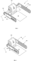
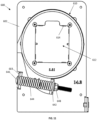
- the system 1 is shown in a stow position with the first bumper 200 down and extended (away from the body assembly 100, and adjacent a vehicle wall) and the second bumper 300 up and retracted (adjacent to the body assembly 100 and away from the vehicle aisle).
- the second bumper 300 being positioned in both the up and retracted position, reduces a tripping hazard that may otherwise be present due to the system 1 extending into the vehicle aisle.
- the system 1 In the stow position, the system 1 is ready to receive a wheeled mobility device in the wheelchair securement area 20.
- a wheelchair passenger can back their wheeled mobility device into the wheelchair securement area 20 and toward the body assembly 100 (whereby the seatback of the wheeled mobility device will be adjacent or touching a backrest extending upward from the body assembly 100, if present).
- Access into the wheelchair securement area 20 from the aisle of the vehicle is made easy by keeping the second bumper 300 in the up position.
- the system 1 is shown in a wheelchair secure position, whereby the first and second bumper 200, 300 are intended to be engaged with opposite sides of the wheeled mobility device and are applying a compressive, securing force on the wheeled mobility device.
- the system 1 is configured to periodically confirm that sufficient compressive force is applied to the wheeled mobility device, and to apply additional force as needed.
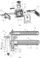
- the system 1 is shown partially exploded into various sub-assemblies, including the body assembly 100 (which holds a rotation motor assembly 400 for the second bumper 300 and the static collar assembly 600 for the first bumper 200), the first bumper 200 (i.e., a "static” or “non-rotating” arm or bumper), the second bumper 300 (i.e., a “rotating” arm or bumper), a release handle assembly 500, and a controller assembly 700.
- the body assembly 100 which holds a rotation motor assembly 400 for the second bumper 300 and the static collar assembly 600 for the first bumper 200
- the first bumper 200 i.e., a "static” or “non-rotating” arm or bumper
- the second bumper 300 i.e., a "rotating” arm or bumper
- a release handle assembly 500 i.e., a "rotating" arm or bumper
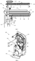
- the first bumper 200 is shown in greater detail in FIG. 6 .
- the bumper 200 is generally comprised of an arm 205, an arm tube 210, and a linear drive 220.
- the arm 205 is generally comprised of a structural member 202, a gripper assembly 204, a cover plate 208 that are configured to interconnect with a plurality of fasteners.
- the gripper assembly 204 includes a grip pad or gripping surface 206 for engagement with a surface of the wheeled mobility device.
- the gripping surface 206 may be a resilient, high friction surface and may be inflatable and/or include moveable fingers or other structures to enhance grip on the wheeled mobility device.
- the arm 205 is connected to the arm tube 210 using a plurality of fasteners and angle brace 212 to provide additional structural rigidity.
- the first bumper 200 may include various lights or speakers to warn vehicle occupants that the bumper 200 is moving, or of imminent movement. Lights and speakers may also be provided on other components of the system 1, including the body assembly 100 and the second bumper 300.
- the arm tube 210 includes a first channel 214 extending from one end of the arm 210 to the other for receiving the linear drive 220.
- the arm tube 210 may include a second channel 216 along at least a portion of its length for receiving a linear drive power assembly 218 (which could be an electrical wiring harness or hydraulic or pneumatic tubes).
- the linear drive 220 as shown is an electrical motor and gear-driven linear actuator with a cylinder 222 holding a piston 224.
- the piston 224 telescopes with the cylinder 222 to change the length of the linear drive 220 as measured from the base 226 of the cylinder 222 to the end 228 of the piston 224.
- the linear drive 220 could alternatively be hydraulically or pneumatically driven.
- the base 226 of the linear drive 220 is secured to the first bumper 200, while the end 228 of the linear drive 220 is secured to the second bumper 300.
- the first bumper 200 may include one or more magnets 230, for instance located along the length of the arm tube 210.
- the magnets 230 may be positioned to be picked up by one or more magnetic proximity sensors for detecting the lateral position of the first bumper 200 (e.g., how far the bumper 200 is extended or retracted into the main body 100).
- a first proximity sensor 112 is located in the body assembly 100 (see FIGS. 13-14 ) for detecting magnet 230 when the first bumper 200 is fully extended.
- the second bumper 300 is shown in greater detail in FIG. 7 .
- the bumper 300 is generally comprised of an arm 305 and an arm tube 310.
- the arm 305 is generally comprised of a structural member 302, a gripper assembly 304, and a cover plate 308 that are configured to interconnect with a plurality of fasteners.
- the gripper assembly 304 includes a grip pad or gripping surface 306 for engagement with a surface of the wheeled mobility device.
- the arm 305 is connected to the arm tube 310 using a plurality of fasteners and an angle brace 312 to provide additional structural rigidity.
- the second bumper 300 may include various lights or speakers to warn vehicle occupants that the bumper 300 is moving, or of imminent movement.
- the bumper 300 includes an oval-shaped LED light 313 and associated power harness 315 are provided (although any shape and number of lights may be used).
- the bumper 300 further includes a bezel 317 on one side and a docking bumper 319 on the other side.
- the docking bumper 319 is soft and resilient, may be constructed of a rubber-type material, and is designed to engage and nest with brake nub 114 on the side of the body assembly 100 when the bumper 300 is in the fully retracted position (see FIG. 1 ).
- a magnet 321 is provided adjacent the docking bumper 319 for pickup by the sixth proximity sensor 116.
- the arm tube 310 has a cross-section that corresponds to and is slightly smaller than the cross-section of the arm tube 210 of the first bumper 200, whereby the arm tube 310 can be received inside of the arm tube 210.
- both arm tubes 210, 310 have a square cross-section and are designed to telescope.
- the non-rotating bumper 200 which is designed to not rotate, can prevent the rotating bumper 300 from rotating when the arm tubes 210, 310 are telescopingly engaged.
- the arm tube 310 includes a channel 314 extending from one end of the arm 210, and has dimensions slightly larger than and can receive the linear drive 220 (both the cylinder 222 and the piston 224).
- the piston 224 is configured to extend through the channel 314, and the end 228 of the piston 228 is configured to engage with the release handle assembly 500 to lock the bumpers 200, 300 together.
- the release handle assembly 500 can be used to disengage the bumpers 200, 300, whereby the bumpers 200, 300 can be moved by hand in an emergency to release a secured wheeled mobility device.
- the second bumper 300 may include one or more magnets 330, for instance located around the radius or on various sides of the arm tube 310, or along the length of the arm tube 310. In this case, there are two magnets 330, one each in corresponding apertures 331 on respective sides of the arm tube 310 that are offset from each other by approximately 90°.
- the magnets 330 may be positioned to be picked up by one or more magnetic proximity sensors located in the body assembly 100 for detecting the rotational or lateral position of the first bumper 300 (e.g., whether the bumper 300 is up or down and/or how far the bumper 300 is extended or retracted into the main body 100).
- a fourth proximity sensor 450 is located in the body assembly 100 (on the rotation motor assembly 400, see FIGS. 8-10 ) for detecting magnets 330 when the second bumper 300 is fully extended (because there are two magnets 300 that are offset by 90°, the fourth proximity sensor 450 can detect full extension when the bumper 300 is both up and down).
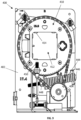
- the inside surface of the aperture 412 may include a plurality of rollers 414 spaced about the periphery of the aperture 412, in this case sixteen rollers 414 (eight around the periphery of the aperture 412 at one end, and eight at the other end), which allow the second bumper 300 to move along the lateral axis 10 freely back and forth.
- a low friction sliding surface may be provided.
- the rotating collar assembly 410 may comprise a rotating collar 416, the rotating collar sprocket 418, and a stow bar 420, which are secured together in the configuration shown using fasteners.
- the rotating collar 416 is configured to hold a rotation stopper ring 422, a first bearing ring 424, a buffer plate 426, and a second bearing ring 428, in the order shown in FIG. 10 , about its periphery.
- the rotation stopper ring 422 is configured to rotate with the rotating collar assembly 410, and includes a tab 430 that holds a magnet 432.
- the buffer plate 426 being disposed between the first and second bearing rings 424, 428, does not rotate with the rotating collar assembly 410, but rather rotates with respect to both the rotating collar assembly 410 and the rotating frame 402.
- the release handle assembly 500 is comprised of manual release handle 510 and release handle latch 530.
- the release handle latch 530 is secured to the second bumper 300 using a fastener.
- the manual release handle 510 is configured to couple the end 228 of the piston 224 to the second bumper 300, and the release handle latch 530 holds the manual release handle 510 in a locked position.
- the manual release handle 510 may take the form as a lever, with a grip portion 512 at one end and a pivot point at the other end, where the pivot end of the handle 510 includes a bar or pin 514.
- the grip portion 512 is connected to the pin 514 by at least one lever arm, in this case two lever arms 516.
- FIG. 1 the release handle assembly 500 is comprised of manual release handle 510 and release handle latch 530.
- the release handle latch 530 is secured to the second bumper 300 using a fastener.
- the manual release handle 510 is configured to couple the end 228 of the piston 224 to the second bumper 300, and the release handle
- the lever arms 516 include a projection 518 on their underside, where the projection serves as the pivot point for the handle 510.
- This configuration creates an over-center type lock, because the pin 514 is positioned between the projection 518 and the grip portion 512.
- the piston 224 pulls on pin 514, it urges the grip portion 512 end of the handle 510 further into engagement with the release handle latch 530.
- the controller assembly 700 includes a printed circuit board 710 and a controller 720. Collectively, the controller assembly 700 provides a system by which securement of a wheeled mobility device may be automated.
- the controller assembly 700 collectively may provide a computing device 730 that can perform some or all of the processes described above and below.
- the computing device 730 may include a processor 750, storage 752, an input/output (I/O) interface 754, and a communications bus756.
- the bus 756 connects to and enables communication between the processor 750 and the components of the computing device 730 in accordance with known techniques. Note that in some computing devices there may be multiple processors incorporated therein, and in some systems there may be multiple computing devices.
- Storage 752 may include memory, such as Random Access Memory (RAM), Read Only Memory (ROM), flash memory, etc., which is directly accessible.
- Storage may also include a secondary storage device, such as a hard disk or disks (which may be internal or external), which is accessible with additional interface hardware and software as is known and customary in the art.
- a computing device 730 may have multiple memories (e.g., RAM and ROM), multiple secondary storage devices, and multiple removable storage devices (e.g., USB drive and optical drive).
- the computing device 730 may be located onboard a wheeled mobility device securement system, or may be located remotely in the vehicle or elsewhere.
- the computing device 730 may be programmed to or includes a computer program product that may be configured to: monitor or ascertain various characteristics of one or more of the vehicle, the wheeled mobility device securement system (including but not limited to the types of securement systems described herein), the wheeled mobility device, and the passenger; and control and automate the securement of the wheeled mobility device and passenger in the system 1.
- the computing device 110 may operate with machine language and receive relevant information, signals, data or input from one or more sensors, devices, or other external sources (e.g., proximity sensors 112, 116, 438, 440, 450, 460), to inform the securement process.
- the processor 750 may be configured to communicate with the vehicle operator and/or the wheelchair passenger thru one or more optional interface panels 760.
- the panels 760 may contain command switches or buttons that produce signals, as well as indicator lights, audible alarms, and voice, with optional text or full graphic displays with touch-sensing capabilities.
- the panels 760 may be a wall-mounted unit, a wired or wireless remote control, or even an application running on a tablet or mobile device, such as an iPhone.
- the computing device 730 may be configured to receive signals from the vehicle 30 representative of the status and/or various dynamic conditions of the vehicle, including but not limited to: vehicle stopped; vehicle neutralized, in gear, out of gear, in park, powered down, etc.; vehicle brake applied; vehicle accelerator applied; steering wheel position; vehicle door status; and any other information that may be accessible from the vehicle systems.
- the computing device 730 is programmed to receive signals or inputs from one or more sensors concerning the position of a moveable bumper, which may include any number of different sensors such as magnetic proximity sensors or contact switches.
- the computing device 730 is also programmed to receive signals or inputs concerning the pressure being applied to a wheeled mobility device by the moveable bumper.
- the computing device 730 is programmed to receive signals or inputs concerning the voltage and current being provided to the motor.
- the computing device 730 may be programmed to control motor speed using pulse width modulation (hereinafter "PWM").
- PWM pulse width modulation
- the computing device 730 may be programmed to ensure that the bumper does not provide more than a threshold amount of pressure on the wheeled mobility device.
- the computing device 730 can monitor the current being provided to the motor and to open the circuit (i.e., turn the motor off) when the current exceeds a threshold amount.
- the computing device 730 may be programmed to ensure that the bumper is maintaining a threshold amount of pressure on the wheeled mobility device during transit by continuously cycling the motor on (closing the circuit) with a predetermined frequency (e.g., turn motor on once every second) and monitoring current until it hits a predetermined threshold amount (after which the motor is turned off).
- the above-described computing device 730 can be programmed for use with the embodiment of FIGS. 1-17 . For example, after a wheeled mobility device is backed into the securement area and a "secure" button is pushed by either the vehicle operator or wheelchair passenger, a signal is sent to the computing device 730 to begin the securement process.
- the computing device 730 responds by activating the motor in the linear drive 220 to extend the second bumper 300 from the position shown in FIG. 1 to the position shown in FIG. 2 .
- the computing device 730 can control the extension speed of bumper 300 to a first speed by using PWM and control the force that can be applied by the bumper 300 by monitoring and limiting the current to the motor.
- the computing device 730 will then activate the rotation motor 404 to rotate the bumper 300 downward from the position shown in FIG. 2 to the position shown in FIG. 3 .
- the computing device 730 can control the rotation speed of bumper 300 to a second speed by using PWM and control the force that can be applied by the bumper 300 by monitoring and limiting the current to the motor 404.
- the computing device 730 will monitor the rotational position of the bumper 300 during the rotation process and will stop the rotation motor 404 when it receives a signal from one or more sensors that are indicative of bumpers 300 being rotated to the down position. For instance, the computing device 730 will stop the rotation motor 404 when proximity sensor 440 senses magnet 432.
- the computing device 730 will then activate the motor of the linear drive 220 to retract the bumpers 200, 300 into the body assembly 100 from the position shown in FIG. 3 to the position shown in FIG. 4 (until the bumpers 200, 300 touch the sides of the wheeled mobility device).
- the computing device 730 can control the approach speed of bumpers 200, 300 (how fast they move toward each other) to a third speed by using PWM and control the force that can be applied by the bumpers 200, 300 by monitoring and limiting the current to the motor of the linear drive 220.
- the computing device 730 will monitor the current being provided to the motor of the linear drive 220, and stop the motor when the current exceeds a third threshold amount that is indicative of an obstruction blocking the path of the bumpers 200, 300 (e.g., the wheelchair).
- the computing device 730 is programmed to cause the system 1 to apply a final securing force to the wheeled mobility device in response to: (1) a signal from a vehicle operator or passenger button; (2) a signal from the vehicle indicative of the vehicle leaving park.
- the computing device 730 will activate the motor of the linear drive 220 to retract the bumpers 200, 300 into the body assembly 100 until the bumpers 200, 300 apply a sufficient amount of force the sides of the wheeled mobility device.
- the computing device 730 can control the approach speed of bumpers 200, 300 (how fast they move toward each other) to a fourth speed by using PWM, wherein the fourth speed may be less than the third speed.
- the computing device can also control the force that can be applied by the bumpers 200, 300 by monitoring and limiting the current to the motor of the linear drive 220.
- the computing device 730 will monitor the current being provided to the motor of the linear drive 220, and stop the motor when the current exceeds a fourth threshold amount, wherein the fourth threshold amount may be greater than the third threshold amount.
- the fourth threshold amount is selected so as to provide sufficient restraining force to the wheeled mobility device, but to not damage the wheeled mobility device.
- the computing device 730 While moving the bumpers 200, 300 to the wheelchair secure position, the computing device 730 will also monitor the lateral position of the bumpers 200, 300 during the retraction process and will stop the motor of the linear drive 220 if it receives a signal from one or more sensors that are indicative of bumpers 200, 300 being fully retracted (an error condition). For instance, the computing device 730 will stop the motor of the linear drive when proximity sensor 460 ceases to sense magnet 458 (which, as explained above, is indicative of either bumper 200 or bumper 300 being fully retracted).
- the computing device 730 may also be programmed to re-secure the wheeled mobility device to account for movement of the wheeled mobility device during transit and to ensure that adequate restraint force is continuously applied to the wheeled mobility device.
- the computing device 730 may be programmed to periodically activate the motor of the linear drive 220 to retract the bumpers 200, 300 into the body assembly 100 until the bumpers 200, 300 apply a sufficient amount of force the sides of the wheeled mobility device.
- the computing device 730 activates the motor for the linear drive 220 once every second.
- the computing device 730 can control the approach speed of bumpers 200, 300 (how fast they move toward each other) to a fifth speed by using PWM, wherein the fifth speed may be the same or less than the fourth speed.
- the computing device can also control the force that can be applied by the bumpers 200, 300 by monitoring and limiting the current to the motor of the linear drive 220.
- the computing device 730 will monitor the current being provided to the motor of the linear drive 220, and stop the motor when the current exceeds a fifth threshold amount, wherein the fifth threshold amount may be the same or greater than the fourth threshold amount.
- the fourth threshold amount is selected so as to provide sufficient restraining force to the wheeled mobility device, but to not damage the wheeled mobility device.
- the computing device 730 While moving the bumpers 200, 300 to the wheelchair secure position, the computing device 730 will also monitor the lateral position of the bumpers 200, 300 during the retraction process and will stop the motor of the linear drive 220 if it receives a signal from one or more sensors that are indicative of bumpers 200, 300 being fully retracted (an error condition). For instance, the computing device 730 will stop the motor of the linear drive when proximity sensor 460 ceases to sense magnet 458 (which, as explained above, is indicative of either bumper 200 or bumper 300 being fully retracted).
- the system 1 described herein has additional use with other restraints, one example being tie-down based systems that utilize motorized tensioners for the wheeled mobility device tie-downs. See, for example, the system disclosed in U.S. Patent Application No. 15/605,872 .
- the computing system 730 disclosed herein can be used to periodically apply power to a motorized retractor until a measured force being applied to the wheeled mobility device by the motorized retractor (e.g., the current being provided to the motor) reaches a predetermined threshold.
- arm, finger, joints, extremities, and other terms may be used herein, including in the claims, to refer to the various structures constituting the various embodiments of the wheeled mobility device securement system.
- these terms connote a particular shape and configuration (e.g., that the structures resemble human appendages), the claims are not intended to be limited as such unless a specific shape or configuration is specifically called out in the claims.
Landscapes
- Health & Medical Sciences (AREA)
- Public Health (AREA)
- Life Sciences & Earth Sciences (AREA)
- Animal Behavior & Ethology (AREA)
- General Health & Medical Sciences (AREA)
- Veterinary Medicine (AREA)
- Engineering & Computer Science (AREA)
- Mechanical Engineering (AREA)
- Transportation (AREA)
- Motorcycle And Bicycle Frame (AREA)
- Handcart (AREA)
Claims (15)
- Sicherungssystem (1) für eine mit Rädern versehene Mobilitätsvorrichtung, wobei das Sicherungssystem umfasst:einen ersten Elektromotor (20), der bewirkt, dass eine mit Rädern versehene Mobilitätsvorrichtungsrückhaltevorrichtung (200, 300) eine Kraft auf eine mit Rädern versehene Mobilitätsvorrichtung ausübt; dadurch gekennzeichnet, dassein Computersystem (730) einen Prozessor (750) enthält, der konfiguriert ist, um eine Eingabe zu empfangen, die indikativ für die Kraft ist, die auf die mit Rädern versehene Mobilitätsvorrichtung ausgeübt wird, und den ersten Elektromotor (20) zu aktivieren, um zu bewirken, dass die mit Rädern versehene Mobilitätsvorrichtungsrückhaltevorrichtung (200, 300) eine zusätzliche Kraft auf die mit Rädern versehene Mobilitätsvorrichtung (200, 300) ausübt, undder Prozessor (750) programmiert ist, um die Sicherung der mit Rädern versehenen Mobilitätsvorrichtung zu bestätigen, während des Transports durch periodisches Aktivieren des ersten Elektromotors (220) mit einer vorbestimmten Frequenz, wobei der erste Elektromotor (220) aktiviert bleibt, bis die Eingabe einen Schwellenwert überschreitet.
- Sicherungssystem (1) nach Anspruch 1, wobei die mit Rädern versehene Mobilitätsvorrichtung Rückhaltevorrichtung (200, 300) ein Stoßfänger (200, 300) ist.
- Sicherungssystem (1) nach Anspruch 2, wobei:der erste Elektromotor (220) dazu ausgelegt ist, den Stoßfänger (200, 300) in eine erste Richtung zu bewegen, in Richtung eines Eingriffs mit der mit Rädern versehenen Mobilitätsvorrichtung und in eine zweite Richtung weg von einem Eingriff mit der mit Rädern versehenen Mobilitätsvorrichtung, ferner dadurch gekennzeichnet, dassder Prozessor (750) konfiguriert ist, um:eine erste Eingabe zu empfangen, die eine Position des Stoßfängers (200, 300) angibt,den ersten Elektromotor (220) selektiv zu aktivieren, um den Stoßfänger (200, 300) in die erste Richtung und die zweite Richtung zu bewegen,wobei die Eingabe, die die Kraft angibt, eine zweite Eingabe ist, die die Kraft angibt, die auf die mit Rädern versehene Mobilitätsvorrichtung ausgeübt wird,der Prozessor (750) programmiert ist, um die Sicherung der mit Rädern versehenen Mobilitätsvorrichtung zu bestätigen, durch Aktivieren des ersten Elektromotors (220), um den Stoßfänger (200, 300) in die erste Richtung zu bewegen, bis die zweite Eingabe eine erste Schwellenkraft überschreitet; und wobei der Schwellenwert eine zweite Schwellenkraft ist.
- Sicherungssystem (1) nach Anspruch 3, wobei die zweite Schwellenkraft gleich oder größer als die erste Schwellenkraft ist.
- Sicherungssystem (1) nach einem der Ansprüche 3-4, wobei der Prozessor (750) programmiert ist, um: die mit Rädern versehene Mobilitätsvorrichtung durch Betreiben des ersten Elektromotors (220) bei einer ersten Geschwindigkeit zu sichern und die mit Rädern versehene Mobilitätsvorrichtung durch Betreiben des ersten Elektromotors (220) bei einer zweiten Geschwindigkeit zu sichern, wobei die erste Geschwindigkeit gleich oder größer als die zweite Geschwindigkeit ist.
- Sicherungssystem (1) nach einem der Ansprüche 3-5, wobei der Prozessor (750) ferner programmiert ist, um: die mit Rädern versehene Mobilitätsvorrichtung vor dem Sichern der mit Rädern versehenen Mobilitätsvorrichtung zu erfassen, durch Aktivieren des ersten Elektromotors (220), um den Stoßfänger (200, 300) in die erste Richtung zu bewegen bis die zweite Eingabe eine dritte Schwellenkraft überschreitet, wobei die dritte Schwellenkraft größer als die erste Schwellenkraft ist.
- Sicherungssystem (1) nach einem der Ansprüche 3-6, wobei der Prozessor (750) programmiert ist, um: die mit Rädern versehene Mobilitätsvorrichtung durch Betreiben des ersten Elektromotors (220) bei einer ersten Geschwindigkeit zu sichern und die mit Rädern versehene Mobilitätsvorrichtung durch Betreiben des ersten Elektromotors (220) bei einer zweiten Geschwindigkeit zu sichern, wobei die erste Geschwindigkeit gleich oder größer als die zweite Geschwindigkeit ist.
- Sicherungssystem (1) nach einem der Ansprüche 3-7, wobei ein Näherungssensor (112, 116, 438, 440, 450, 460) die erste Eingabe bereitstellt.
- Sicherungssystem (1) nach Anspruch 1, wobei die mit Rädern versehene Mobilitätsvorrichtungsrückhaltevorrichtung ein Aufroller ist.
- Sicherungssystem (1) nach einem der Ansprüche 1-9, wobei die vorbestimmte Frequenz aus der Gruppe ausgewählt ist, die ungefähr einmal alle drei Sekunden bis ungefähr viermal pro Sekunde umfasst.
- Sicherungssystem (1) nach einem der Ansprüche 1-9, wobei die vorbestimmte Frequenz mindestens ungefähr einmal alle drei Sekunden beträgt.
- Sicherungssystem (1) nach einem der Ansprüche 1-9, wobei die vorbestimmte Frequenz mindestens ungefähr einmal alle zwei Sekunden beträgt.
- Sicherungssystem (1) nach einem der Ansprüche 1-9, wobei die vorbestimmte Frequenz mindestens ungefähr einmal pro Sekunde beträgt.
- Sicherungssystem (1) nach einem der Ansprüche 1-13, wobei der Prozessor (750) ferner programmiert ist eine Geschwindigkeit des ersten Elektromotors (220) unter Verwendung einer Pulsbreitemodulation zu steuern.
- Sicherungssystem (1) nach einem der Ansprüche 1-14, wobei die Eingabe einen Strom, der dem Elektromotor (220) bereitgestellt wird, angibt.
Applications Claiming Priority (3)
| Application Number | Priority Date | Filing Date | Title |
|---|---|---|---|
| US201962885428P | 2019-08-12 | 2019-08-12 | |
| US201962885481P | 2019-08-12 | 2019-08-12 | |
| PCT/US2020/045839 WO2021030382A1 (en) | 2019-08-12 | 2020-08-12 | Mobility device securement system |
Publications (3)
| Publication Number | Publication Date |
|---|---|
| EP4013364A1 EP4013364A1 (de) | 2022-06-22 |
| EP4013364C0 EP4013364C0 (de) | 2024-12-18 |
| EP4013364B1 true EP4013364B1 (de) | 2024-12-18 |
Family
ID=72243206
Family Applications (1)
| Application Number | Title | Priority Date | Filing Date |
|---|---|---|---|
| EP20761946.1A Active EP4013364B1 (de) | 2019-08-12 | 2020-08-12 | Sicherungssystem für mobilitätsvorrichtung |
Country Status (7)
| Country | Link |
|---|---|
| US (3) | US11819462B2 (de) |
| EP (1) | EP4013364B1 (de) |
| JP (1) | JP7393522B2 (de) |
| KR (1) | KR102606927B1 (de) |
| AU (1) | AU2020327974B2 (de) |
| CA (1) | CA3147671A1 (de) |
| WO (1) | WO2021030382A1 (de) |
Families Citing this family (2)
| Publication number | Priority date | Publication date | Assignee | Title |
|---|---|---|---|---|
| WO2021030382A1 (en) | 2019-08-12 | 2021-02-18 | Valeda Company, Llc | Mobility device securement system |
| WO2025245308A1 (en) * | 2024-05-23 | 2025-11-27 | Valeda Company, Llc | Mobility device type detection for a mobility device securement system |
Family Cites Families (10)
| Publication number | Priority date | Publication date | Assignee | Title |
|---|---|---|---|---|
| US6231283B1 (en) * | 1997-09-15 | 2001-05-15 | Thomas R. Stowers | Vehicle restraint apparatus |
| US7425110B2 (en) * | 2005-01-18 | 2008-09-16 | M & M, Inc. | Vehicular wheelchair docking and capture apparatus |
| WO2008039810A2 (en) * | 2006-09-25 | 2008-04-03 | Valeda Company Llc (D/B/A Q'straint) | Wheelchair passenger station |
| WO2010040138A2 (en) | 2008-10-05 | 2010-04-08 | Valeda Company Llc D/B/A "Q'straint" | Wheelchair passenger securement station |
| US10350120B2 (en) | 2008-10-05 | 2019-07-16 | Valeda Company, Llc | Wheelchair passenger securement system with movable bumper |
| US10071004B2 (en) | 2013-05-13 | 2018-09-11 | Valeda Company | Two point wheelchair securement system |
| US9585800B2 (en) | 2014-07-15 | 2017-03-07 | 4One, Llc | Mobility securement system |
| KR20160092112A (ko) * | 2015-01-26 | 2016-08-04 | 주식회사이지무브 | 휠체어용 자세 유지 장치 |
| US10688959B2 (en) * | 2018-07-26 | 2020-06-23 | GM Global Technology Operations LLC | Vehicle occupant restraint system for wheelchair users and vehicle incorporating the system |
| WO2021030382A1 (en) | 2019-08-12 | 2021-02-18 | Valeda Company, Llc | Mobility device securement system |
-
2020
- 2020-08-12 WO PCT/US2020/045839 patent/WO2021030382A1/en not_active Ceased
- 2020-08-12 CA CA3147671A patent/CA3147671A1/en active Pending
- 2020-08-12 KR KR1020227008320A patent/KR102606927B1/ko active Active
- 2020-08-12 AU AU2020327974A patent/AU2020327974B2/en active Active
- 2020-08-12 EP EP20761946.1A patent/EP4013364B1/de active Active
- 2020-08-12 JP JP2022508850A patent/JP7393522B2/ja active Active
- 2020-08-12 US US16/991,153 patent/US11819462B2/en active Active
-
2023
- 2023-11-20 US US18/513,769 patent/US12336940B2/en active Active
-
2025
- 2025-06-12 US US19/236,456 patent/US20250302680A1/en active Pending
Also Published As
| Publication number | Publication date |
|---|---|
| KR102606927B1 (ko) | 2023-11-29 |
| CA3147671A1 (en) | 2021-02-18 |
| US20250302680A1 (en) | 2025-10-02 |
| JP7393522B2 (ja) | 2023-12-06 |
| US12336940B2 (en) | 2025-06-24 |
| US20240082080A1 (en) | 2024-03-14 |
| EP4013364C0 (de) | 2024-12-18 |
| US11819462B2 (en) | 2023-11-21 |
| KR20220044827A (ko) | 2022-04-11 |
| JP2022544654A (ja) | 2022-10-20 |
| AU2020327974B2 (en) | 2025-03-06 |
| AU2020327974A1 (en) | 2022-03-03 |
| EP4013364A1 (de) | 2022-06-22 |
| WO2021030382A1 (en) | 2021-02-18 |
| US20210045944A1 (en) | 2021-02-18 |
Similar Documents
| Publication | Publication Date | Title |
|---|---|---|
| US20250302680A1 (en) | Mobility device securement system | |
| EP2042144B1 (de) | Kompaktes Rollstuhlrückhaltesystem mit Gehäuse | |
| US20100086375A1 (en) | Wheelchair Passenger Securement Station | |
| US20160304004A1 (en) | Child restraint system | |
| EP2777667A2 (de) | Rollstuhlsicherungssystem und Vorrichtung für rollstuhlgerechte Fahrzeuge | |
| US20030190208A1 (en) | Mobility aid securement for vehicles | |
| AU2018248792B2 (en) | Height adjustable wheelchair docking system | |
| US20240294133A1 (en) | Energy Management System | |
| US11027696B2 (en) | Vehicle seat belt systems | |
| CN118700969A (zh) | 一种安全带卷收器及一种汽车座椅和车辆 | |
| CN105667449B (zh) | 包括预紧器和松弛消除器的座椅安全带卷收器 | |
| US20250360033A1 (en) | Mobility device type detection for a mobility device securement system | |
| CN120245836A (zh) | 一种座椅系统、车辆以及座椅系统的回位控制方法 |
Legal Events
| Date | Code | Title | Description |
|---|---|---|---|
| STAA | Information on the status of an ep patent application or granted ep patent |
Free format text: STATUS: UNKNOWN |
|
| STAA | Information on the status of an ep patent application or granted ep patent |
Free format text: STATUS: THE INTERNATIONAL PUBLICATION HAS BEEN MADE |
|
| PUAI | Public reference made under article 153(3) epc to a published international application that has entered the european phase |
Free format text: ORIGINAL CODE: 0009012 |
|
| STAA | Information on the status of an ep patent application or granted ep patent |
Free format text: STATUS: REQUEST FOR EXAMINATION WAS MADE |
|
| 17P | Request for examination filed |
Effective date: 20220228 |
|
| AK | Designated contracting states |
Kind code of ref document: A1 Designated state(s): AL AT BE BG CH CY CZ DE DK EE ES FI FR GB GR HR HU IE IS IT LI LT LU LV MC MK MT NL NO PL PT RO RS SE SI SK SM TR |
|
| DAV | Request for validation of the european patent (deleted) | ||
| DAX | Request for extension of the european patent (deleted) | ||
| GRAP | Despatch of communication of intention to grant a patent |
Free format text: ORIGINAL CODE: EPIDOSNIGR1 |
|
| STAA | Information on the status of an ep patent application or granted ep patent |
Free format text: STATUS: GRANT OF PATENT IS INTENDED |
|
| INTG | Intention to grant announced |
Effective date: 20240715 |
|
| GRAS | Grant fee paid |
Free format text: ORIGINAL CODE: EPIDOSNIGR3 |
|
| GRAA | (expected) grant |
Free format text: ORIGINAL CODE: 0009210 |
|
| STAA | Information on the status of an ep patent application or granted ep patent |
Free format text: STATUS: THE PATENT HAS BEEN GRANTED |
|
| AK | Designated contracting states |
Kind code of ref document: B1 Designated state(s): AL AT BE BG CH CY CZ DE DK EE ES FI FR GB GR HR HU IE IS IT LI LT LU LV MC MK MT NL NO PL PT RO RS SE SI SK SM TR |
|
| REG | Reference to a national code |
Ref country code: CH Ref legal event code: EP |
|
| REG | Reference to a national code |
Ref country code: DE Ref legal event code: R096 Ref document number: 602020043388 Country of ref document: DE |
|
| REG | Reference to a national code |
Ref country code: IE Ref legal event code: FG4D |
|
| U01 | Request for unitary effect filed |
Effective date: 20250107 |
|
| U07 | Unitary effect registered |
Designated state(s): AT BE BG DE DK EE FI FR IT LT LU LV MT NL PT RO SE SI Effective date: 20250116 |
|
| PG25 | Lapsed in a contracting state [announced via postgrant information from national office to epo] |
Ref country code: HR Free format text: LAPSE BECAUSE OF FAILURE TO SUBMIT A TRANSLATION OF THE DESCRIPTION OR TO PAY THE FEE WITHIN THE PRESCRIBED TIME-LIMIT Effective date: 20241218 |
|
| PG25 | Lapsed in a contracting state [announced via postgrant information from national office to epo] |
Ref country code: NO Free format text: LAPSE BECAUSE OF FAILURE TO SUBMIT A TRANSLATION OF THE DESCRIPTION OR TO PAY THE FEE WITHIN THE PRESCRIBED TIME-LIMIT Effective date: 20250318 |
|
| PG25 | Lapsed in a contracting state [announced via postgrant information from national office to epo] |
Ref country code: GR Free format text: LAPSE BECAUSE OF FAILURE TO SUBMIT A TRANSLATION OF THE DESCRIPTION OR TO PAY THE FEE WITHIN THE PRESCRIBED TIME-LIMIT Effective date: 20250319 |
|
| PG25 | Lapsed in a contracting state [announced via postgrant information from national office to epo] |
Ref country code: RS Free format text: LAPSE BECAUSE OF FAILURE TO SUBMIT A TRANSLATION OF THE DESCRIPTION OR TO PAY THE FEE WITHIN THE PRESCRIBED TIME-LIMIT Effective date: 20250318 |
|
| PG25 | Lapsed in a contracting state [announced via postgrant information from national office to epo] |
Ref country code: SM Free format text: LAPSE BECAUSE OF FAILURE TO SUBMIT A TRANSLATION OF THE DESCRIPTION OR TO PAY THE FEE WITHIN THE PRESCRIBED TIME-LIMIT Effective date: 20241218 |
|
| PG25 | Lapsed in a contracting state [announced via postgrant information from national office to epo] |
Ref country code: PL Free format text: LAPSE BECAUSE OF FAILURE TO SUBMIT A TRANSLATION OF THE DESCRIPTION OR TO PAY THE FEE WITHIN THE PRESCRIBED TIME-LIMIT Effective date: 20241218 |
|
| PG25 | Lapsed in a contracting state [announced via postgrant information from national office to epo] |
Ref country code: ES Free format text: LAPSE BECAUSE OF FAILURE TO SUBMIT A TRANSLATION OF THE DESCRIPTION OR TO PAY THE FEE WITHIN THE PRESCRIBED TIME-LIMIT Effective date: 20241218 |
|
| PG25 | Lapsed in a contracting state [announced via postgrant information from national office to epo] |
Ref country code: IS Free format text: LAPSE BECAUSE OF FAILURE TO SUBMIT A TRANSLATION OF THE DESCRIPTION OR TO PAY THE FEE WITHIN THE PRESCRIBED TIME-LIMIT Effective date: 20250418 |
|
| PG25 | Lapsed in a contracting state [announced via postgrant information from national office to epo] |
Ref country code: SK Free format text: LAPSE BECAUSE OF FAILURE TO SUBMIT A TRANSLATION OF THE DESCRIPTION OR TO PAY THE FEE WITHIN THE PRESCRIBED TIME-LIMIT Effective date: 20241218 |
|
| PG25 | Lapsed in a contracting state [announced via postgrant information from national office to epo] |
Ref country code: CZ Free format text: LAPSE BECAUSE OF FAILURE TO SUBMIT A TRANSLATION OF THE DESCRIPTION OR TO PAY THE FEE WITHIN THE PRESCRIBED TIME-LIMIT Effective date: 20241218 |
|
| U20 | Renewal fee for the european patent with unitary effect paid |
Year of fee payment: 6 Effective date: 20250827 |
|
| PGFP | Annual fee paid to national office [announced via postgrant information from national office to epo] |
Ref country code: GB Payment date: 20250827 Year of fee payment: 6 |
|
| PLBE | No opposition filed within time limit |
Free format text: ORIGINAL CODE: 0009261 |
|
| STAA | Information on the status of an ep patent application or granted ep patent |
Free format text: STATUS: NO OPPOSITION FILED WITHIN TIME LIMIT |
|
| 26N | No opposition filed |
Effective date: 20250919 |