EP4013261B1 - Praktischer haartrockner - Google Patents
Praktischer haartrockner Download PDFInfo
- Publication number
- EP4013261B1 EP4013261B1 EP19758750.4A EP19758750A EP4013261B1 EP 4013261 B1 EP4013261 B1 EP 4013261B1 EP 19758750 A EP19758750 A EP 19758750A EP 4013261 B1 EP4013261 B1 EP 4013261B1
- Authority
- EP
- European Patent Office
- Prior art keywords
- holder
- hair dryer
- tube part
- front operational
- air
- Prior art date
- Legal status (The legal status is an assumption and is not a legal conclusion. Google has not performed a legal analysis and makes no representation as to the accuracy of the status listed.)
- Active
Links
Images
Classifications
-
- A—HUMAN NECESSITIES
- A45—HAND OR TRAVELLING ARTICLES
- A45C—PURSES; LUGGAGE; HAND CARRIED BAGS
- A45C11/00—Receptacles for purposes not provided for in groups A45C1/00-A45C9/00
- A45C11/04—Spectacle cases; Pince-nez cases
-
- A—HUMAN NECESSITIES
- A45—HAND OR TRAVELLING ARTICLES
- A45D—HAIRDRESSING OR SHAVING EQUIPMENT; EQUIPMENT FOR COSMETICS OR COSMETIC TREATMENTS, e.g. FOR MANICURING OR PEDICURING
- A45D20/00—Hair drying devices; Accessories therefor
- A45D20/04—Hot-air producers
- A45D20/08—Hot-air producers heated electrically
- A45D20/10—Hand-held drying devices, e.g. air douches
- A45D20/12—Details thereof or accessories therefor, e.g. nozzles, stands
- A45D2020/126—Stands therefor
- A45D2020/128—Stands therefor involving features of the hand-held hair dryer
Definitions
- the present disclosure relates to a hair dryer especially for drying hair.
- CN104783472A discloses a strong magnetic attraction type automatic head-oscillatable hair dryer.
- CN203087949U discloses a rotary hair dryer.
- CN208581919U discloses a hair dryer bracket with an oscillation function.
- CN104621944A discloses a suction cup type safety hair dryer.
- US 1,716,580 discloses an hair dryer which can be attached to an electric vacuum cleaner.
- the hair dryer has a pivotable leg and a pair of supports.
- DE 29 51 562 discloses an hair dryer with a protruding handle portion.
- Another hair dryer is disclosed in DE 20 2013 001 172 U1 .
- An object of the present disclosure is to provide a hair dryer which is capable of conveniently achieving switch between a hand-held operation mode and a hands-free operation mode.
- a hair dryer having the features of claim 1.
- a hair dryer which comprises a body and a holder or holding mechanism connected thereto, wherein the holder is configured to be reversibly convertible from a handle configuration to a support configuration via its own metamorphosis in shape. This fast conversion idea enables convenient switching of the hair dryer between a hand-held operation mode and a hands-free operation mode.
- metalamorphosis in shape of the holder on its own means the shape change or transformation of the holder by itself, and does not include the following case: the holder does not substantively change in the structure and shape, and only changes in position relative to the body of the hair dryer, for example, in pivotal positions.
- the holder has a connecting end connected to the body and an opposite free end (non-connecting end).
- the free end of the holder is configured to be expandable in shape so as to enlarge its support footprint(s). With the free end being expanded, the holder may quickly switch or transform from an initial handle to a fixing support, and thus the hair dryer being conveniently switched to perform the hands-free air blowing operation.
- the holder may include more than one wing (preferably 2-4 wings, for example three wings) encircling its free end so that the holder acts as the handle when the wings do not flare out and acts as the support when the wings flare out.
- a holder is structurally simple and can very conveniently achieve the air blowing mode switch or transformation.
- a fixing seat or fixing disc may be fast connected to (e.g., plugged into) the free end of the holder, or even an expandable supporting disc or support webs may be ejected or pulled out of the free end, use of the "open-umbrella" variation or modification of the present disclosure is obviously more advantageous in structural integration or convenience in use.
- the distal ends (flarable ends) of the wings may be disposed at the free end of the holder and flare outwardly 0-90° therefrom ("forwardly open” mode); or the proximal ends (connecting and fixing ends) of the wings may be disposed at the free end of the holder so that the distal ends of the wings may flare outwardly or flip 90-180°towards the free end of the holder ("reversely open” mode).
- the "forwardly open” mode structure is simpler and more convenient to operate; however, the “reversely open” mode structure may enable the holder to extend longer or higher (within a range approximate to the length of the wings) so as to adjust the air blowing height.
- the body of the hair dryer may be integrally formed with a hollow handle in a way that the holder of the present disclosure may be received in the hollow handle and be pulled and ejected out of the hollow handle.
- the transformation of the holder to the handle may be implemented by receiving the holder in the hollow handle; the transformation from the handle to the fixing support may be implemented by pulling the holder out of the hollow handle and making its free end expand.
- the distal ends of the wings may substantially be in the same supporting surface (horizon) as the free end of the holder. Such a structure makes the support firmer.
- the free end of the holder may be provided with a suction cup or friction pad.
- the free ends of the wings may also be provided with a friction pad respectively. Such a structure may further enhance the support stability.
- the holder is telescopic in its longitudinal direction, for example, the holder is configured as a telescopic sleeve or a multi-stage antenna structure.
- a telescopic sleeve may be designed to be adjusted in its telescopic length and be retained or fixed at any length position; or may be designed as a multi-stage positioning sleeve so that it can be retained or fixed at different set length positions.
- the holder is movably connected to the body of the hair dryer.
- the movable connection manner facilitates adjustment of the air blowing angle and air blowing direction.
- the body of the hair dryer is relative to the holder and comprises a housing, parts located in the housing and various stationary accessories disposed on the housing.
- the above movable connection may either be a separable or detachable connection or an inseparable or undetachable connection. However only detachable connections are covered by the present invention.
- the holder may be connected to the body of the hair dryer via a hinge.
- the pivotal connection manner not only enables the holder to conveniently adjust the air blowing angle when the holder is used as the support, but also enables the holder to be folded towards the body for purpose of convenient carrying or enables the holder to be received at a proper position of the body to facilitate storage.
- the hinge may be such a hinge that can be positioned at any pivot angle, i.e., can be arbitrarily pivoted and stay or be fixed at a current pivot position.
- the hinge may be a multi-stage positioning hinge that can be pivoted and positioned at different set angles.
- the hinge may be further fixed to a rotatable shaft disposed on the holder.
- a rotatable shaft disposed on the holder.
- Such a structure may cater to adjustment of the air blowing angle as well as the air blowing direction.
- the rotatable shaft may be rotated to stay or be fixed at an arbitrary current orientation; or may be fixed at different set orientations.
- the holder may be connected to the body of the hair dryer via a magnetic coupling.
- the coupling consists of an iron ball disposed on one of the body and the holder and a socket including a ring magnet disposed on the other of the body and the holder for magnetically receiving the iron ball therein.
- a movable connection is simpler in structure, not only enables adjustment of the air blowing angle and air blowing direction when the holder is used as a support, but also facilitate fast separation of the holder from the body of the hair dryer, and facilitates the carrying and storage.
- the magnetic coupling is not limited to a specific combined structure of the iron ball and the ring magnet, and any suitable magnetic coupling connection is feasible: for example, a ferromagnetic member-magnet combination or a magnet-magnet combination.
- the holder may also be connected to the body of the hair dryer via a freely-deformable rope (flexible rope).
- a freely-deformable rope flexible rope
- Such structure may also achieve multi adjustments of the air blowing angle, air blowing direction and air blowing height.
- the holder may be connected to the body of the hair dryer via a friction ball mechanism.
- the friction ball mechanism may comprise a receptacle, a rotatable ball and a friction pad, and the ball is undetachably received in the receptacle under a tight fit through the friction pad encircling the ball (the holder, under action of an external force against the friction force, can rotate in any direction and stay at a current position when the external force is removed).
- the receptacle may be disposed on one of the body and the holder, and the ball may be connected to the other of the body and the holder via a connecting rod.
- the holder may be retracted towards the body of the hair dryer so that the whole hair dryer, not in use, can have a single consistent tube configuration such as a cylinder, an elliptical cylinder, a spindle-shaped tube or a rectangular tube.
- At least one portion of the body may have an incomplete tube section.
- the section of the holder is complementary with said incomplete tube section of said at least one portion of the body so as to form a substantially complete tube section.
- the body may include in linear a front operational tube part with a complete tube section and a rear tube part with an incomplete tube section, the front operational tube part is configured to perform a blowing operation and has an air inlet formed at its rear end, the rear tube part has an air air-incoming chamber formed therein and also designed to receive a power supply line for powering the front operational tube part, the air-incoming chamber is in air communication with the air inlet of the front operational tube part, and the holder section is complementary with the incomplete tube section of the rear tube part so as to form a substantially complete tube section corresponding to the complete tube section of the front operational tube part when the holder is completely contracted and retracted towards the rear tube part.
- the body includes, as defined in claim 1, in linear a front operational tube part and a rear tube part, the front operational tube part is configured to perform a blowing operation and has an air inlet formed at its rear end, the rear tube part has an air-incoming chamber formed therein and also designed to receive a power supply line for powering the front operational tube part, the air-incoming chamber is in air communication with the air inlet of the front operational tube part, the front operational tube part has a section which is substantially consistent with that of the rear tube part, and wherein the rear tube part is further designed to receive the detached holder therein.
- the rear tube part may be removably or detachably connected to the front operational tube part, such that the hair dryer becomes light and handy when in use by removal of the rear tube part.
- Such a single tube configuration makes the hair dryer of the present disclosure look very brief, neat and beautiful when in a not-in-use state, for example, when the hair dryer is stored, minimizes the occupied space and eliminates the trouble caused by the messy power supply line.
- the hair dryer of the present disclosure may further comprise a cover which is used to at least cover a rear end of the rear tube part when the power supply line is received in a chamber of the rear tube part.
- the holder may be connected to a side of the body of the hair dryer.
- the side connection or lateral connection may enable the holder to be connected to around a center of gravity of the body of the hair dryer so as to facilitate operation and use.
- the holder may be connected at other positions, for example, at a position nearby an end opposite to the air outlet in a longitudinal direction of the body of the hair dryer.
- a magnet may be attached to the free end of the holder or the free end of the holder may be designed as a clip to facilitate flexible fixation and use of the hair dryer on different occasions.
- the hair dryer of the present disclosure it is possible to conveniently enable the holder to switch between the handle configuration for the hand-held mode and the support configuration for the hands-free mode, thereby making the its use more flexible and convenient.
- the holder achieves fast and flexible adjustment of the air blowing angle, air blowing direction and air blowing height by means of simple structures.
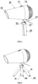
- FIGS. 1-3 respectively illustrate a hair dryer according to a first embodiment of the present disclosure, generally including a body 10 and a holder 20 connected thereto.
- the body 10 is provided with a switch 11, an external power supply line 12, an air outlet 13, an air inlet 14, a heating element and a motor (not specifically shown), and the like.
- FIG. 1 shows a schematic view of a hand-held state of the hair dryer according to the first embodiment, wherein the holder 20 is contracted or folded into a rod shape to facilitate the gripping operation by a hand.
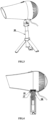
- FIG. 2 shows a schematic view of a hands-free state of the hair dryer according to the first embodiment, wherein the holder 20 is unfolded or flared out as a fixing support so that the hair dray is fixed on a table surface for hands-free blowing operation.
- FIG. 3 shows a schematic view of a hands-free state of the hair dryer according to the first embodiment, wherein the holder 20 is unfolded or flared out as a fixing support as shown in FIG. 2 , and additionally extends in its longitudinal direction to raise the air blowing position.
- the holder 20 is connected to a side of the body 10 via a hinge 21, pivotable in a vertical plane (illustrated paper surface).
- the hinge 21 may be such a hinge that can be positioned at any pivot angle, i.e., the hinge can be arbitrarily manually pivoted and stay at a current pivot position.
- the hinge 21 may be a multi-stage positioning hinge that can be manually pivoted and positioned at different set angles.
- the holder 20 includes a shaft 22, a hinge seat 23 at an upper end (a connecting end) of the shaft, and three flarable wings 24 located at a lower portion of the shaft. Distal ends of the wings 24 form support legs, and proximal ends of the wings 24 are connected to the shaft 22.
- the distal ends thereof may also flush with a lower end of the shaft 22 in the same plane to facilitate firm support on an appropriate table surface.
- the distal ends of the wings 24 are provided with friction pads 240, and the lower end of the shaft 22 is also provided with a suction cup or friction pad 220, as shown in FIGS. 2 and 3 .
- the air blowing angle (an angle between the air blowing direction and the shaft 22) can be adjusted very conveniently by the above pivotal connection.
- the hinge seat 23 is rotatably mounted relative to the shaft 22 to facilitate adjusting of the air blowing direction.
- the hinge seat 23 may be manually rotated relative to the shaft 22 and stay or be fixed at any current orientation, or may be fixed at different set orientations.
- the distal ends or flarable ends of the wings are disposed at a free end (lower end of the shaft 22) of the holder 20 and can flare outwardly 0-90° therefrom ("forwardly open” mode).
- the "forwardly open” mode structure is simpler and more convenient to operate; however, the "reversely open” mode structure can enable the holder to extend longer or higher (within a range approximate to the length of the wings) so that adjustment of the air blowing height can still be conveniently achieved in a case that a telescopic sleeve described below is dispensed with.
- a body portion of the shaft 22 is formed by a multi-stage (e.g., two to five stages) telescopic sleeve 25 so that the shaft 22 can be extended or retracted to adjust the air blowing height.
- the telescopic sleeve 25 may be designed in a way that the telescopic length thereof can be manually adjusted and retained or fixed at any length position.
- the telescopic sleeve 25 may be designed as a multi-stage positioning sleeve so that it can stay or be fixed at set length positions.
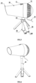
- FIGS. 4-6 respectively illustrate a hair dryer according to a second embodiment of the present disclosure, which is generally similar to the embodiment shown in FIGS. 1-3 , wherein the holder in FIG. 4 is shown in a sectional manner with the same reference numbers denoting the same parts; the difference lies in that the holder 20 in this embodiment is connected to the body of the hair dryer via a magnetic coupling, in place of the rotatable hinge seat structure in the first embodiment.
- the magnetic coupling comprises a socket 16 disposed on the body 10 and an iron ball disposed in the holder 20, wherein a ring magnet 17 is disposed in the socket 16.
- the iron ball 26 and the magnet 17 in the socket 16 mate with each other by attraction, such that the holder 20 can rotate arbitrarily and be fast detachably connected to the body 10 of the hair dryer.
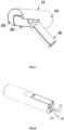
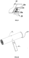
- FIGS. 7-8 illustrate a hair dryer according to a third embodiment of the present disclosure.
- the configuration of the present embodiment is also different from that of the second embodiment, besides a different movable connection of the holder 20 with the body 10.
- FIG. 7 shows a state in which the holder 20 extends out of the body 10 of the hair dryer 10. It can be seen that the holder 20 is connected to the body 10 of the hair dryer via a friction ball mechanism.
- FIG. 8 in a retracted state, the body 10 and the holder 20 as a whole form a continuous cylinder shape.
- the friction ball mechanism comprises a receptacle 16a disposed on the body 10, and a metal rotatable ball 26a disposed at an upper end of the holder 20.
- the rotatable ball 26a may be connected together with the holder 20 via a threaded structure.
- a friction pad 17a is disposed in the receptacle 16a.
- the section of the holder 20 is complementary with the cylindrical section of the rear tube part 102 so as to form a substantially complete cylindrical section (a circular section) corresponding to that of the front operational tube part 101 when the holder 20 is completely contracted and retracted towards the rear tube part 102.
- FIG. 8 further shows a cover 18.
- the cover 18 is used to cover a rear end of the rear tube part 102.
- the cover 18 may also be designed to completely cover the rear end of the hair dryer.
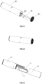
- FIGs. 10-12 illustrate a hair dryer according to a fourth embodiment of the present disclosure.
- the connection between the holder 20 and the body 10 is a separable or detachable connection in the form of a magnetic coupling of the second embodiment as shown in FIGs. 4-6 .
- the whole hair dryer of this embodiment looks like a perfect cylinder when the detached holder 20, like the power supply line, is received in the chamber 103 of the body 10 and covered by the cover 18 ( FIGs. 11 and 12 ).
- FIG. 13 illustrates a hair dryer according to a fifth embodiment of the present disclosure.
- the hair dryer in the present embodiment is similar to that of the fourth embodiment in structure and different in that the front operational tube part 101 is not integrally formed with the rear tube part 102 but connected thereto detachably or removably by means of screw or snap-fit connection.
- Such a configuration can bring such an advantage: the hair dryer will become light and handy when in use by removal of the rear tube part 102.
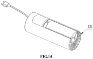
- FIG. 14 illustrates a hair dryer according to a sixth embodiment of the present disclosure.
- the hair dryer in the present embodiment is similar to that of the third or fourth embodiment in structure and different in omitting the rear tube part 102 (thereby making the whole hair dryer shorter), and meanwhile enabling the holder 20 to flip forward (towards the air outlet 13) relative to the body 10 and enabling the whole hair dryer to form a single continuous cylindrical configuration.
- the hair dryers of the first and second embodiment may also employ the single cylindrical configuration of the third or fourth or fifth or sixth embodiment, within the limitations of the appended claims.
Landscapes
- Cleaning And Drying Hair (AREA)
Claims (8)
- Haartrockner, umfassend einen Körper (10) und einen Halter (20), der damit verbunden ist, wobei der Halter (20) dazu konfiguriert ist, durch seine eigene Verwandlung hinsichtlich der Form zwischen einer Griffkonfiguration und einer Trägerkonfiguration umwandelbar zu sein, dadurch gekennzeichnet, dass der Halter (20) über eine magnetische Kopplung (26, 17) lösbar mit dem Körper (10) verbunden und relativ zu dem Körper (10) einziehbar ist, sodass der gesamte Haartrockner in einer einzelnen und durchgängigen Rohrkonfiguration vorliegen kann, wenn er nicht verwendet wird, der Körper (10) linear einen vorderen operativen Rohrteil (101) und einen hinteren Rohrteil (102) beinhaltet, der vordere operative Rohrteil (101) dazu konfiguriert ist, einen Blasvorgang durchzuführen, und einen Lufteinlass aufweist, der an seinem hinteren Ende gebildet ist, der hintere Rohrteil (102) eine Lufteintrittskammer aufweist, die darin gebildet ist, und auch dazu ausgestaltet ist, eine Stromversorgungsleitung (12) zum Versorgen des vorderen operativen Rohrteils (101) mit Strom aufzunehmen, die Lufteintrittskammer in Luftverbindung mit dem Lufteinlass des vorderen operativen Rohrteils (101) steht, der vordere operative Rohrteil (101) ein Teilstück aufweist, das im Wesentlichen durchgängig mit dem des hinteren Rohrteils (102) ist, und der hintere Rohrteil (102) ferner dazu ausgestaltet ist, den gelösten Halter (20) darin aufzunehmen.
- Haartrockner nach Anspruch 1, wobei der Halter (20) ein Ende, das mit dem Körper (10) verbunden ist, und ein gegenüberliegendes freies Ende, das dazu konfiguriert ist, erweiterbar zu sein, um seine Trägergrundfläche(n) zu vergrößern, aufweist.
- Haartrockner nach Anspruch 2, wobei der Halter (20) mindestens einen Flügel (24) beinhaltet, der sein freies Ende umschließt, sodass der Halter (20) als Griff dient, wenn die Flügel (24) nicht ausgebreitet sind, und als Träger dient, wenn die Flügel (24) ausgebreitet sind.
- Haartrockner nach Anspruch 3, wobei distale Enden des mindestens einen Flügels (24) jeweils mit einem Reibbelag (240) versehen sind.
- Haartrockner nach Anspruch 1, wobei der Halter (20) in seiner Längsrichtung teleskopisch ist.
- Haartrockner nach Anspruch 1, wobei die Kopplung aus einer Eisenkugel (26), die an einem von dem Körper (10) und dem Halter (20) angeordnet ist, und einer Aufnahme (16), die einen Ringmagneten (17) beinhaltet, der an dem anderen von dem Körper (10) und dem Halter (20) angeordnet ist, um die Eisenkugel (26) magnetisch darin aufzunehmen, besteht.
- Haartrockner nach Anspruch 1, wobei der hintere Rohrteil (102) lösbar mit dem vorderen operativen Rohrteil (101) verbunden ist.
- Haartrockner nach Anspruch 1, wobei die einzelne Rohrkonfiguration eine Zylinderkonfiguration ist.
Applications Claiming Priority (2)
| Application Number | Priority Date | Filing Date | Title |
|---|---|---|---|
| EP2019071601 | 2019-08-12 | ||
| PCT/EP2019/072952 WO2021028062A1 (en) | 2019-08-12 | 2019-08-28 | Convenient hair dryer |
Publications (3)
| Publication Number | Publication Date |
|---|---|
| EP4013261A1 EP4013261A1 (de) | 2022-06-22 |
| EP4013261B1 true EP4013261B1 (de) | 2025-06-18 |
| EP4013261C0 EP4013261C0 (de) | 2025-06-18 |
Family
ID=67659867
Family Applications (1)
| Application Number | Title | Priority Date | Filing Date |
|---|---|---|---|
| EP19758750.4A Active EP4013261B1 (de) | 2019-08-12 | 2019-08-28 | Praktischer haartrockner |
Country Status (2)
| Country | Link |
|---|---|
| EP (1) | EP4013261B1 (de) |
| WO (1) | WO2021028062A1 (de) |
Family Cites Families (7)
| Publication number | Priority date | Publication date | Assignee | Title |
|---|---|---|---|---|
| US1716580A (en) * | 1928-06-12 | 1929-06-11 | Thomas Jones | Hair drier |
| DE2951562A1 (de) * | 1979-12-21 | 1981-07-02 | Cerena Produktions- und Handelsgesellschaft für den Friseurbedarf mbH, 5650 Solingen | Haartrockner |
| CN203087949U (zh) | 2012-12-28 | 2013-07-31 | 熊峥 | 一种旋转式电吹风机 |
| DE202013001172U1 (de) * | 2013-02-04 | 2013-03-05 | Christoph Haas | Haartrockner mit großer Griffmulde - senkrecht stehend |
| CN104621944A (zh) | 2013-11-11 | 2015-05-20 | 郑州麓宸电子技术有限公司 | 一种吸盘式安全吹风机 |
| CN104783472A (zh) | 2015-03-31 | 2015-07-22 | 广西智通节能环保科技有限公司 | 强磁铁吸合式自动摇头吹风机 |
| CN208581919U (zh) | 2018-06-26 | 2019-03-08 | 林心旺 | 一种具有摇摆功能的电风吹支架 |
-
2019
- 2019-08-28 WO PCT/EP2019/072952 patent/WO2021028062A1/en not_active Ceased
- 2019-08-28 EP EP19758750.4A patent/EP4013261B1/de active Active
Also Published As
| Publication number | Publication date |
|---|---|
| EP4013261A1 (de) | 2022-06-22 |
| WO2021028062A1 (en) | 2021-02-18 |
| EP4013261C0 (de) | 2025-06-18 |
Similar Documents
| Publication | Publication Date | Title |
|---|---|---|
| CN111227476B (zh) | 便捷电吹风机 | |
| CN109488843A (zh) | 一种自拍装置 | |
| US7487787B2 (en) | Easy-to-operate sunshade | |
| US8081873B2 (en) | Hair dryer mount with oscillating holder for use with a hand-held hair dryer | |
| CN105443949A (zh) | 一种自拍杆结构 | |
| WO1999020935A1 (en) | Positionable flashlight and holder | |
| CN209511452U (zh) | 一种自拍装置 | |
| EP1731055A1 (de) | Klappschirm | |
| US7611104B1 (en) | Stand for supporting an object | |
| EP4013261B1 (de) | Praktischer haartrockner | |
| US5857263A (en) | Reconfigurable hair drying apparatus | |
| US12376659B2 (en) | Convenient hair dryer | |
| CA2561456A1 (en) | Easel with support structure | |
| RU2785536C1 (ru) | Фен для волос | |
| CN204986297U (zh) | 一种自拍杆结构 | |
| KR200481373Y1 (ko) | 헤어드라이기 | |
| US7849848B2 (en) | Erectable and stowable decorative firebowl and stand assembly | |
| CN217771667U (zh) | 一种便携式折叠伞 | |
| CN211715366U (zh) | 一种折叠型风扇 | |
| CN213096657U (zh) | 吹风机支架 | |
| CN110561965B (zh) | 一种美术绘画作品用多角度风干装置 | |
| CN210152396U (zh) | 具有附件挂接装置的折叠帐篷 | |
| CN209250711U (zh) | 三脚架自拍杆 | |
| CN211794809U (zh) | 吹风机支架 | |
| CN222937599U (zh) | 具有插地结构的自拍杆架 |
Legal Events
| Date | Code | Title | Description |
|---|---|---|---|
| STAA | Information on the status of an ep patent application or granted ep patent |
Free format text: STATUS: UNKNOWN |
|
| STAA | Information on the status of an ep patent application or granted ep patent |
Free format text: STATUS: THE INTERNATIONAL PUBLICATION HAS BEEN MADE |
|
| PUAI | Public reference made under article 153(3) epc to a published international application that has entered the european phase |
Free format text: ORIGINAL CODE: 0009012 |
|
| STAA | Information on the status of an ep patent application or granted ep patent |
Free format text: STATUS: REQUEST FOR EXAMINATION WAS MADE |
|
| 17P | Request for examination filed |
Effective date: 20220125 |
|
| AK | Designated contracting states |
Kind code of ref document: A1 Designated state(s): AL AT BE BG CH CY CZ DE DK EE ES FI FR GB GR HR HU IE IS IT LI LT LU LV MC MK MT NL NO PL PT RO RS SE SI SK SM TR |
|
| DAV | Request for validation of the european patent (deleted) | ||
| DAX | Request for extension of the european patent (deleted) | ||
| STAA | Information on the status of an ep patent application or granted ep patent |
Free format text: STATUS: EXAMINATION IS IN PROGRESS |
|
| 17Q | First examination report despatched |
Effective date: 20230928 |
|
| GRAP | Despatch of communication of intention to grant a patent |
Free format text: ORIGINAL CODE: EPIDOSNIGR1 |
|
| STAA | Information on the status of an ep patent application or granted ep patent |
Free format text: STATUS: GRANT OF PATENT IS INTENDED |
|
| INTG | Intention to grant announced |
Effective date: 20250402 |
|
| GRAS | Grant fee paid |
Free format text: ORIGINAL CODE: EPIDOSNIGR3 |
|
| GRAA | (expected) grant |
Free format text: ORIGINAL CODE: 0009210 |
|
| STAA | Information on the status of an ep patent application or granted ep patent |
Free format text: STATUS: THE PATENT HAS BEEN GRANTED |
|
| AK | Designated contracting states |
Kind code of ref document: B1 Designated state(s): AL AT BE BG CH CY CZ DE DK EE ES FI FR GB GR HR HU IE IS IT LI LT LU LV MC MK MT NL NO PL PT RO RS SE SI SK SM TR |
|
| REG | Reference to a national code |
Ref country code: GB Ref legal event code: FG4D |
|
| REG | Reference to a national code |
Ref country code: CH Ref legal event code: EP |
|
| PGFP | Annual fee paid to national office [announced via postgrant information from national office to epo] |
Ref country code: GB Payment date: 20250626 Year of fee payment: 7 |
|
| REG | Reference to a national code |
Ref country code: DE Ref legal event code: R096 Ref document number: 602019071266 Country of ref document: DE |
|
| REG | Reference to a national code |
Ref country code: CH Ref legal event code: EP |
|
| REG | Reference to a national code |
Ref country code: IE Ref legal event code: FG4D |
|
| U01 | Request for unitary effect filed |
Effective date: 20250625 |
|
| REG | Reference to a national code |
Ref country code: CH Ref legal event code: PK Free format text: BERICHTIGUNGEN |
|
| RAP4 | Party data changed (patent owner data changed or rights of a patent transferred) |
Owner name: CHARGUERAUD, THIERRY Owner name: WANG, XIAOBING Owner name: LI, LIANGQING |
|
| RIN2 | Information on inventor provided after grant (corrected) |
Inventor name: CHARGUERAUD, THIERRY Inventor name: WANG, XIAOBING Inventor name: LI, LIANGQING |
|
| U07 | Unitary effect registered |
Designated state(s): AT BE BG DE DK EE FI FR IT LT LU LV MT NL PT RO SE SI Effective date: 20250828 |
|
| PG25 | Lapsed in a contracting state [announced via postgrant information from national office to epo] |
Ref country code: GR Free format text: LAPSE BECAUSE OF FAILURE TO SUBMIT A TRANSLATION OF THE DESCRIPTION OR TO PAY THE FEE WITHIN THE PRESCRIBED TIME-LIMIT Effective date: 20250919 Ref country code: NO Free format text: LAPSE BECAUSE OF FAILURE TO SUBMIT A TRANSLATION OF THE DESCRIPTION OR TO PAY THE FEE WITHIN THE PRESCRIBED TIME-LIMIT Effective date: 20250918 |
|
| U20 | Renewal fee for the european patent with unitary effect paid |
Year of fee payment: 7 Effective date: 20250909 |
|
| PG25 | Lapsed in a contracting state [announced via postgrant information from national office to epo] |
Ref country code: HR Free format text: LAPSE BECAUSE OF FAILURE TO SUBMIT A TRANSLATION OF THE DESCRIPTION OR TO PAY THE FEE WITHIN THE PRESCRIBED TIME-LIMIT Effective date: 20250618 |
|
| PG25 | Lapsed in a contracting state [announced via postgrant information from national office to epo] |
Ref country code: RS Free format text: LAPSE BECAUSE OF FAILURE TO SUBMIT A TRANSLATION OF THE DESCRIPTION OR TO PAY THE FEE WITHIN THE PRESCRIBED TIME-LIMIT Effective date: 20250918 |
|
| PG25 | Lapsed in a contracting state [announced via postgrant information from national office to epo] |
Ref country code: IS Free format text: LAPSE BECAUSE OF FAILURE TO SUBMIT A TRANSLATION OF THE DESCRIPTION OR TO PAY THE FEE WITHIN THE PRESCRIBED TIME-LIMIT Effective date: 20251018 |
|
| PG25 | Lapsed in a contracting state [announced via postgrant information from national office to epo] |
Ref country code: SM Free format text: LAPSE BECAUSE OF FAILURE TO SUBMIT A TRANSLATION OF THE DESCRIPTION OR TO PAY THE FEE WITHIN THE PRESCRIBED TIME-LIMIT Effective date: 20250618 |