EP4013192A2 - Röntgenröhrenaufnahme - Google Patents
Röntgenröhrenaufnahme Download PDFInfo
- Publication number
- EP4013192A2 EP4013192A2 EP21210615.7A EP21210615A EP4013192A2 EP 4013192 A2 EP4013192 A2 EP 4013192A2 EP 21210615 A EP21210615 A EP 21210615A EP 4013192 A2 EP4013192 A2 EP 4013192A2
- Authority
- EP
- European Patent Office
- Prior art keywords
- ray tube
- connector
- data processor
- input
- cathode
- Prior art date
- Legal status (The legal status is an assumption and is not a legal conclusion. Google has not performed a legal analysis and makes no representation as to the accuracy of the status listed.)
- Pending
Links
- 238000000034 method Methods 0.000 claims abstract description 29
- 238000004891 communication Methods 0.000 claims description 21
- 230000008878 coupling Effects 0.000 claims description 6
- 238000010168 coupling process Methods 0.000 claims description 6
- 238000005859 coupling reaction Methods 0.000 claims description 6
- 238000010438 heat treatment Methods 0.000 claims description 5
- 238000003780 insertion Methods 0.000 claims description 4
- 230000037431 insertion Effects 0.000 claims description 4
- 238000010586 diagram Methods 0.000 description 12
- 238000004590 computer program Methods 0.000 description 8
- 230000008569 process Effects 0.000 description 6
- 230000006870 function Effects 0.000 description 5
- 230000007547 defect Effects 0.000 description 3
- 230000007257 malfunction Effects 0.000 description 3
- 238000012544 monitoring process Methods 0.000 description 3
- 230000008859 change Effects 0.000 description 2
- 238000003745 diagnosis Methods 0.000 description 2
- 230000003993 interaction Effects 0.000 description 2
- 238000012423 maintenance Methods 0.000 description 2
- 230000003287 optical effect Effects 0.000 description 2
- 239000003990 capacitor Substances 0.000 description 1
- 239000000969 carrier Substances 0.000 description 1
- 238000006243 chemical reaction Methods 0.000 description 1
- 230000000694 effects Effects 0.000 description 1
- 239000004973 liquid crystal related substance Substances 0.000 description 1
- 238000004519 manufacturing process Methods 0.000 description 1
- 238000012986 modification Methods 0.000 description 1
- 230000004048 modification Effects 0.000 description 1
- 238000012545 processing Methods 0.000 description 1
- 230000000644 propagated effect Effects 0.000 description 1
- 230000004044 response Effects 0.000 description 1
- 239000004065 semiconductor Substances 0.000 description 1
- 230000001953 sensory effect Effects 0.000 description 1
- 238000012546 transfer Methods 0.000 description 1
- 230000000007 visual effect Effects 0.000 description 1
Images



Classifications
-
- H—ELECTRICITY
- H05—ELECTRIC TECHNIQUES NOT OTHERWISE PROVIDED FOR
- H05G—X-RAY TECHNIQUE
- H05G1/00—X-ray apparatus involving X-ray tubes; Circuits therefor
- H05G1/02—Constructional details
- H05G1/04—Mounting the X-ray tube within a closed housing
- H05G1/06—X-ray tube and at least part of the power supply apparatus being mounted within the same housing
-
- H—ELECTRICITY
- H01—ELECTRIC ELEMENTS
- H01J—ELECTRIC DISCHARGE TUBES OR DISCHARGE LAMPS
- H01J35/00—X-ray tubes
- H01J35/02—Details
- H01J35/025—X-ray tubes with structurally associated circuit elements
-
- H—ELECTRICITY
- H01—ELECTRIC ELEMENTS
- H01J—ELECTRIC DISCHARGE TUBES OR DISCHARGE LAMPS
- H01J35/00—X-ray tubes
- H01J35/02—Details
-
- H—ELECTRICITY
- H01—ELECTRIC ELEMENTS
- H01J—ELECTRIC DISCHARGE TUBES OR DISCHARGE LAMPS
- H01J35/00—X-ray tubes
- H01J35/02—Details
- H01J35/04—Electrodes ; Mutual position thereof; Constructional adaptations therefor
- H01J35/06—Cathodes
-
- H—ELECTRICITY
- H05—ELECTRIC TECHNIQUES NOT OTHERWISE PROVIDED FOR
- H05G—X-RAY TECHNIQUE
- H05G1/00—X-ray apparatus involving X-ray tubes; Circuits therefor
- H05G1/08—Electrical details
- H05G1/10—Power supply arrangements for feeding the X-ray tube
-
- H—ELECTRICITY
- H05—ELECTRIC TECHNIQUES NOT OTHERWISE PROVIDED FOR
- H05G—X-RAY TECHNIQUE
- H05G1/00—X-ray apparatus involving X-ray tubes; Circuits therefor
- H05G1/08—Electrical details
- H05G1/26—Measuring, controlling or protecting
-
- H—ELECTRICITY
- H01—ELECTRIC ELEMENTS
- H01J—ELECTRIC DISCHARGE TUBES OR DISCHARGE LAMPS
- H01J2235/00—X-ray tubes
- H01J2235/02—Electrical arrangements
-
- H—ELECTRICITY
- H05—ELECTRIC TECHNIQUES NOT OTHERWISE PROVIDED FOR
- H05G—X-RAY TECHNIQUE
- H05G1/00—X-ray apparatus involving X-ray tubes; Circuits therefor
- H05G1/08—Electrical details
- H05G1/26—Measuring, controlling or protecting
- H05G1/30—Controlling
Definitions
- X-ray tubes can be configured with a receptacle by which input voltage can be supplied to a cathode of the X-ray tube causing the cathode to emit radiative energy as X-rays.
- the receptacle described herein can include an inner volume in which electrical components can be located.
- the receptacle electronics can be configured to control one or more aspects of the X-ray tube and can enable diagnostic analysis of X-ray tube operation.
- an apparatus in one aspect, can include a X-ray tube including a cathode and an input receptacle coupled to the cathode.
- the input receptacle can include a connector configured within the input receptacle.
- the connector can operatively couple the cathode and the input receptacle.
- the connector can include at least one circuit configured to receive an input signal via the input receptacle.
- the input signal can be received as an auxiliary supply voltage.
- the at least one circuit can be configured to generate an output signal indicative of at least one operational characteristic of the X-ray tube.
- the connector can be configured for insertion into and removal from an inner volume of the input receptacle.
- the X-ray tube is a bipolar X-ray tube.
- at least one operational characteristic of the X-ray tube can include a filament temperature, a filament current, an electron emission current, or at least one parameter associated with a beam shape emitted by the X-ray tube.
- the connector can include a transceiver configured to establish a communication channel between the connector and a data processor of a computing device coupled to the connector via the communication channel.
- the transceiver can be powered by a portion of the auxiliary supply voltage.
- the data processor can be configured to determine a tube setting associated with the at least eon operational characteristic of the X-ray tube.
- the tube setting can correspond to a tube-identifier setting stored in a memory of the computing device.
- the data processor can be configured to transmit the determined setting to a controller coupled to the data processor and to a voltage generator coupled to the input receptacle, which can cause the controller to control the voltage generator to provide at least one of an input voltage to the cathode, or a heating current to the cathode based on the determined setting of the X-ray tube.
- the input signal can be between 20 kV and 400 kV.
- a system in another aspect, can include an X-ray tube including a cathode and an input receptacle coupled to the cathode.
- the input receptacle can include a connector configured within the input receptacle.
- the connector can operatively couple the cathode and the input receptacle.
- the connector can include at least one circuit configured to receive an input signal via the input receptacle.
- the input signal can be received as an auxiliary supply voltage.
- the at least one circuit can be configured to generate an output signal indicative of at least one operational characteristic of the X-ray tube.
- the connector can also include a transceiver configured to transmit the output signal generated via the at least one circuit.
- the system can also include a computing device operatively coupled to the connector via a communication channel established by the transceiver.
- the computing device can include at least one data processor, and a memory storing instructions.
- the instructions when executed by the at least one data processor cause the at least one data processor to perform operations including receiving data characterizing the output signal.
- the instructions further cause the at least one data processor to determine, based on the received data, at least one operational characteristic of the X-ray tube.
- the instructions further cause the at least one data processor to provide the at least one operational characteristic of the X-ray tube.
- the transceiver is powered by a portion of the auxiliary supply voltage.
- at least one operational characteristic of the X-ray tube can include a filament temperature, a filament current, an electron emission current, or at least one parameter associated with a beam shape emitted by the X-ray tube.
- the at least one operational characteristic can be provided in a graphical user interface of a display coupled to the data processor.
- the input signal can be between 20 kV and 400 kV.
- a method in another aspect, can include receiving, by a data processor, data characterizing an output signal generated via at least one circuit located on a connector configured within an input receptacle of an X-ray tube.
- the connector can operatively couple a cathode of the X-ray tube to the input receptacle.
- the at least one circuit can be configured to receive an input signal via the input receptacle.
- the input signal can be received as an auxiliary supply voltage.
- the at least one circuit can also be configured to generate the output signal indicative of at least one operational characteristic of the X-ray tube.
- the method can also include determining, by the data processor and based on the received data, at least one operational characteristic of the X-ray tube.
- the method can further include providing, by the data processor, the at least one operational characteristic of the X-ray tube.
- the connector can be configured for insertion into and removal from an inner volume of the input receptacle.
- the X-ray tube is a bipolar X-ray tube.
- the at least one operational characteristic of the X-ray tube includes a filament temperature, a filament current, an electron emission current, or at least one parameter associated with a beam shape emitted by the X-ray tube.
- the connector can include a transceiver configured to establish a communication channel communicably coupling the connector and the data processor.
- the transceiver can be powered by a portion of the auxiliary supply voltage.
- the method responsive to providing the at least one operational characteristic indicative of a tube-type identifier corresponding to a type of X-ray tube, can also include determining, by the data processor, a tube setting corresponding to the tube-type identifier, and transmitting, by the data processor, the tube setting to a controller coupled to the data processor and to a voltage generator coupled to the input receptacle. When received, the controller controls the voltage generator to provision at least one of an input voltage to the cathode or a heating current to the cathode based on the determined tube setting.
- the input signal is between 20 kV and 400 kV.
- the at least one operational characteristic is provided in a graphical user interface provided in a display coupled to the data processor.
- Determining an operation of an X-ray tube can require external components to be coupled to internal components of the X-ray tube, such as a cathode of the X-ray tube, in order to measure diagnostic data indicative of the operation of the X-ray tube.
- external components such as a cathode of the X-ray tube
- diagnostic data indicative of the operation of the X-ray tube.
- X-ray tube applications may not permit or can be difficult to enable such coupling due to size or space constraints within the X-ray tube or the application environment in which the X-ray tube is operating.
- the use of various wires to couple the X-ray tube or components therein to monitoring systems can also be problematic.
- high voltage tension can be generated at the input receptacle of the X-ray tube, which can unload to internal wiring and cause the wiring to short.
- the wiring used for a grid voltage supply or for a filament voltage supply can experience defects, or shorts, as a result of the high voltage tension. Such defects can cause the X-ray tube, and a monitoring system to which the X-ray tube may be coupled, to operate inaccurately and malfunction.
- the X-ray tube described herein can provide more reliable operational data of the X-ray tube and can reduce or eliminate the incidence of defects or malfunctions within the X-ray tube due to high voltage tension at the supply side of X-ray tube.
- the X-ray tube described herein can include a connector configured within an input receptacle of the X-ray tube.
- the connector an include one or more circuits configured to receive an input signal and to generate an output signal indicative of an operational characteristic of the X-ray tube.
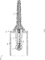
- FIG. 1 is a diagram 100 illustrating an example X-ray tube 105 according to some implementations of the current subject matter.
- the X-ray tube 105 can include an input receptacle 110 coupled to a tube 115.
- the X-ray tube 105 can be an open tube or a closed tube.
- the input receptacle 110 can couple a voltage generator to the tube 105 so as to provide a voltage supply to a cathode configured within the tube 115.
- the X-ray tube 105 can be a monopolar X-ray tube 105 in which a cathode is configured to receive the voltage supply.
- the X-ray tube 105 can be a bipolar X-ray tube 105 in which the cathode and an anode can be configured to receive the voltage supply.
- the voltage supply provided to the X-ray tube 105 via the input receptacle 110 can be a high voltage supply between 20 kV and 400 kV.
- the voltage supplied to the X-ray tube 105 can be supplied at a voltage of 160 kV, 180 kV, 240 kV, 300 kV, or 350 kV.
- FIG. 2 is a diagram 200 illustrating a cross-sectional view of the X-ray tube 105 of FIG. 1 including a connector configured therein according to some implementations of the current subject matter.
- the cross-sectional view shown in FIG. 2 is shown from the perspective of lines A-A shown in FIG. 1 .
- the X-ray tube 105 can include a cathode 205.
- the cathode 205 can coupled to the input receptacle 110 via a connector 210.
- the connector 210 can couple the input receptacle 110 to a cathode and to an anode of the X-ray tube 105.
- the connector 210 can couple the input receptacle 110 to a high voltage feedthrough configured within the input receptacle 110.
- the connector 210 can located within an open space 215 within the input receptacle 110.
- the open space 215 can be configured to allow the connector 210 to be inserted into and/or removed from within the open space 215.
- the connector 210 can be advantageously flat-shaped and can be maintenance free to allow electronics to be configured on the connector 210 without changing the shape of the open space 215 of the input receptacle 110.
- the connector 210 can include electronic circuitry configured to determine operational characteristics of the X-ray tube 105.
- the connector 210 can include a printed circuit board.
- One or more circuits can be configured on the connector 210 to receive an input signal and to generate an output signal indicative of an operational characteristic of the X-ray tube.
- the operational characteristics can include a tube-type identifier, a filament temperature, a filament current, an electron emission current, or at least one parameter associated with a beam shape emitted by the X-ray tube 105.
- FIG. 3 is a diagram 300 illustrating circuitry and components configured on a connector 210 included in the X-ray tube 105 of FIGS. 1-2 according to some implementations of the current subject matter.
- the connector 210 can be configured with a number of electrical components and circuitry to providing a telemetric sub-system by which data characterizing operational characteristics of the X-ray tube 105 can be generated.
- the connector 210 can include one or more supply voltage transformers 305.
- the connector 210 can also include at least one communication transceiver 310.
- the communication transceiver 310 can be configured as a wireless communication transceiver 310 as shown in FIG. 3 , or in some embodiments, the transceiver 310 can be a wired transceiver.
- the connector 210 can also include one or more data processors 315.
- the connector 210 can further include one or more sensors 320.
- the sensors 320 can include a filament temperature sensor, a filament current sensor, an electron emission current sensor, or a beam shape sensor.
- the connector 210 can also include capacitors, inductors, and resistors 325 configured to support the circuits configured on the connector 210.
- the connector 210 can include a printed circuit board and the electrical components and circuitry described above can be configured on the connector 210 via the printed circuit board.
- FIG. 4 is a block diagram 400 illustrating an example system 405 including a monopolar X-ray tube 105 according to some implementations of the current subject matter.
- the connector 210 can be coupled to a cathode 410 of the X-ray tube 105.
- a computing device 415 can be communicatively coupled to the connector 210 of the X-ray tube 105.
- the computing device 415 can include multiple-interconnected components, such as a processor 420, a memory 425, a controller 430, a communication transceiver 435, and a display 440.
- the display 440 can include a graphical user interface (GUI) 445.
- GUI graphical user interface
- the processor 420 can be configured to execute computer-readable instructions stored the memory 425 to perform the methods described in relation to FIG. 6 .
- the memory 425 can further store one or more tube settings and/or tube-type identifier settings associated with the X-ray tube 105.
- the processor 420 can also execute computer-readable instructions stored in the memory 425, which cause the processor 420 to control operations of a voltage generator 450 via the controller 430. In this way, the controller 430 can control an operation of the voltage generator 450 to supply an input signal to the cathode 410 of the X-ray tube 105.
- the communication transceiver 435 can include a wired or a wireless transceiver configured to establish a communication channel with the connector 210 via the transceiver 310 configured with respect to the connector 210.
- the computing device 415 includes a display 440 configured with a GUI 445.
- the GUI 445 can display operational characteristics of the X-ray tube 105 to a user.
- the GUI 445 can display one or more alarms or notifications based on the operational characteristic.
- the alarm can cause the controller 430 to modify an operation of the voltage generator 450 and the input signal provided to the cathode 410 of the X-ray tube 105.
- FIG. 5 is a block diagram 500 illustrating an example system 505 including a bipolar X-ray tube 510 according to some implementations of the current subject matter.
- the bipolar X-ray tube 510 can include a cathode 410 as described in relation to FIG. 4 and an anode 515 coupled to a motor 520.
- the motor 520 can rotate the anode 515 to distribute energy from the cathode 410 on a larger surface area of the anode 515.
- the motor 520 can be coupled to the connector 525.
- the connector 525 can include a microcontroller coupled to the motor 520 and configured to control a rotation speed and power conversion of the motor 520.
- the microcontroller can be configured separately from the connector 525.
- the connector 525 can correspond to the connector 210 described in relation to FIGS. 2 and 3 .
- a second computing device 530 can be communicatively coupled to the anode 515 via the connector 525 of the bipolar X-ray tube 510.
- the X-ray tube 510 can include a single connector (210 or 525), which can be coupled to the cathode 410 and to the anode 515.
- a single voltage generator (450 or 565) can be coupled to a single computing device (415 or 530) to provide an input signal to the cathode 410 and to the anode 515 via the connector 210 or 525.
- the second computing device 530 can be communicatively coupled to the anode 515 via a second connector 525 of the bipolar X-ray tube 510.
- the computing device 530 can include multiple-interconnected components, such as a processor 535, a memory 540, a controller 545, a communication transceiver 550, and a display 555.
- the display 555 can include a graphical user interface (GUI) 560.
- GUI graphical user interface
- the processor 535 can be configured to execute computer-readable instructions stored the memory 540 to perform the methods described in relation to FIG. 6 with respect to the anode 515 instead of the cathode 410.
- the memory 540 can further store one or more tube settings and/or tube-type identifier settings associated with the bipolar X-ray tube 510.
- the processor 535 can also execute computer-readable instructions stored in the memory 540, which cause the processor 535 to control operations of a voltage generator 565 via the controller 545. In this way, the controller 545 can control an operation of the voltage generator 565 to supply an input signal to the anode 515 of the bipolar X-ray tube 510.
- the communication transceiver 550 can include a wired or a wireless transceiver configured to establish a communication channel with the connector 525.
- the computing device 530 includes a display 555 configured with a GUI 560.
- the GUI 560 can display operational characteristics of the bipolar X-ray tube 510 to a user.
- the GUI 560 can display one or more alarms or notifications based on the operational characteristic.
- the alarm can cause the controller 545 to modify an operation of the voltage generator 565 and the input signal provided to the anode 515 of the bipolar X-ray tube 510.
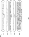
- FIG. 6 is a process flow diagram illustrating an example process 600 of operating the system 405 of FIG. 4 or the system 505 of FIG. 5 according to some implementations of the current subject matter.
- the data processor 420,535 can receive data characterizing an output signal generated via at least one circuit located on a connector 410, 525 configured within an input receptacle 110 of an X-ray tube 105, 510.
- the data processor 420, 535 can determine, based on the received data, at least one operational characteristic of the X-ray tube 105, 510. For example, the data processor can determine that the operational characteristic is one of a tube-type identifier, a filament temperature, a filament current, an electron emission current, or at least one parameter associated with a beam shape emitted by the X-ray tube.
- the data processor 420, 535 can provide the at least one operational characteristic.
- the data processor 420, 535 can provide the operational characteristic via a display 445, 560.
- the data processor 420, 535 can further determine a tube setting corresponding to the tube-type identifier in operation 640.
- the data processor 420, 535 can transmit the tube-setting to a controller 430, 545 coupled to the data processor 420, 535 and to a voltage generator coupled to the input receptacle 110, such as the voltage generator 450, 565 shown in FIG. 5 .
- the controller 430, 545 can control the voltage generator 450, 565 to provide an input voltage to the cathode 410, an input voltage to the anode 515, or a heating current to the cathode 410, based on the determined tube setting.
- the controller 545 can control the voltage generator 565 to provide an input voltage to a microcontroller coupled to the motor 520 and/or to the motor 520 itself directly.
- the input voltage can be provided to the input receptacle as an auxiliary supply voltage.
- Exemplary technical effects of the apparatus, systems, and methods described herein include, by way of non-limiting example, determining an operational characteristic of an X-ray tube using a maintenance free connector configured within the input receptacle of the X-ray tube.
- the operational characteristic can be used by a system in which the X-ray tube is included to control an input signal or input voltage supplied to the input receptacle from a voltage generator. Determining the operational characteristics of the X-ray as described herein can enable operational diagnosis and monitoring of the X-ray tube for a wide variety of applications. For example, determining the operational characteristic of the X-ray tube can be used to monitor filament temperature, filament current, electron emission current, tube-types, and beam shape parameters of the X-ray tube.
- the X-ray tube system configured to perform the methods described herein can provide more accurate diagnosis of operational faults or malfunctions and thus enable more robust operation of X-ray tubes.
- the X-ray system described herein can also include improved interfaces for providing an integrity state. Further, the X-ray tube system can cause a change in operation of the X-ray tube based on the determined operational characteristic which can ensure the X-ray tube operates within acceptable or safe operating parameters.
- the subject matter described herein can be implemented in analog electronic circuitry, digital electronic circuitry, and/or in computer software, firmware, or hardware, including the structural means disclosed in this specification and structural equivalents thereof, or in combinations of them.
- the subject matter described herein can be implemented as one or more computer program products, such as one or more computer programs tangibly embodied in an information carrier (e.g., in a machine-readable storage device), or embodied in a propagated signal, for execution by, or to control the operation of, data processing apparatus (e.g., a programmable processor, a computer, or multiple computers).
- a computer program (also known as a program, software, software application, or code) can be written in any form of programming language, including compiled or interpreted languages, and it can be deployed in any form, including as a stand-alone program or as a module, component, subroutine, or other unit suitable for use in a computing environment.
- a computer program does not necessarily correspond to a file.
- a program can be stored in a portion of a file that holds other programs or data, in a single file dedicated to the program in question, or in multiple coordinated files (e.g., files that store one or more modules, sub-programs, or portions of code).
- a computer program can be deployed to be executed on one computer or on multiple computers at one site or distributed across multiple sites and interconnected by a communication network.
- processors suitable for the execution of a computer program include, by way of example, both general and special purpose microprocessors, and any one or more processor of any kind of digital computer.
- a processor will receive instructions and data from a read-only memory or a random access memory or both.
- the essential elements of a computer are a processor for executing instructions and one or more memory devices for storing instructions and data.
- a computer will also include, or be operatively coupled to receive data from or transfer data to, or both, one or more mass storage devices for storing data, e.g., magnetic, magneto-optical disks, or optical disks.
- Information carriers suitable for embodying computer program instructions and data include all forms of non-volatile memory, including by way of example semiconductor memory devices, (e.g., EPROM, EEPROM, and flash memory devices); magnetic disks, (e.g., internal hard disks or removable disks); magneto-optical disks; and optical disks (e.g., CD and DVD disks).
- semiconductor memory devices e.g., EPROM, EEPROM, and flash memory devices
- magnetic disks e.g., internal hard disks or removable disks
- magneto-optical disks e.g., CD and DVD disks
- optical disks e.g., CD and DVD disks.
- the processor and the memory can be supplemented by, or incorporated in, special purpose logic circuitry.
- the subject matter described herein can be implemented on a computer having a display device, e.g., a CRT (cathode ray tube) or LCD (liquid crystal display) monitor, for displaying information to the user and a keyboard and a pointing device, (e.g., a mouse or a trackball), by which the user can provide input to the computer.
- a display device e.g., a CRT (cathode ray tube) or LCD (liquid crystal display) monitor
- a keyboard and a pointing device e.g., a mouse or a trackball
- Other kinds of devices can be used to provide for interaction with a user as well.
- feedback provided to the user can be any form of sensory feedback, (e.g., visual feedback, auditory feedback, or tactile feedback), and input from the user can be received in any form, including acoustic, speech, or tactile input.
- modules refers to computing software, firmware, hardware, and/or various combinations thereof. At a minimum, however, modules are not to be interpreted as software that is not implemented on hardware, firmware, or recorded on a non-transitory processor readable recordable storage medium (i.e., modules are not software per se ). Indeed “module” is to be interpreted to always include at least some physical, non-transitory hardware such as a part of a processor or computer. Two different modules can share the same physical hardware (e.g., two different modules can use the same processor and network interface). The modules described herein can be combined, integrated, separated, and/or duplicated to support various applications.
- a function described herein as being performed at a particular module can be performed at one or more other modules and/or by one or more other devices instead of or in addition to the function performed at the particular module.
- the modules can be implemented across multiple devices and/or other components local or remote to one another. Additionally, the modules can be moved from one device and added to another device, and/or can be included in both devices.
- the subject matter described herein can be implemented in a computing system that includes a back-end component (e.g., a data server), a middleware component (e.g., an application server), or a front-end component (e.g., a client computer having a graphical user interface or a web browser through which a user can interact with an implementation of the subject matter described herein), or any combination of such back-end, middleware, and front-end components.
- the components of the system can be interconnected by any form or medium of digital data communication, e.g., a communication network. Examples of communication networks include a local area network ("LAN”) and a wide area network (“WAN”), e.g., the Internet.
- LAN local area network
- WAN wide area network
- Approximating language can be applied to modify any quantitative representation that could permissibly vary without resulting in a change in the basic function to which it is related. Accordingly, a value modified by a term or terms, such as “about,” “approximately,” and “substantially,” are not to be limited to the precise value specified. In at least some instances, the approximating language can correspond to the precision of an instrument for measuring the value.
- range limitations can be combined and/or interchanged, such ranges are identified and include all the sub-ranges contained therein unless context or language indicates otherwise.
Landscapes
- Health & Medical Sciences (AREA)
- General Health & Medical Sciences (AREA)
- Toxicology (AREA)
- X-Ray Techniques (AREA)
Applications Claiming Priority (1)
| Application Number | Priority Date | Filing Date | Title |
|---|---|---|---|
| US17/114,849 US11729894B2 (en) | 2020-12-08 | 2020-12-08 | X-ray tube receptacle |
Publications (2)
| Publication Number | Publication Date |
|---|---|
| EP4013192A2 true EP4013192A2 (de) | 2022-06-15 |
| EP4013192A3 EP4013192A3 (de) | 2022-11-23 |
Family
ID=78806268
Family Applications (1)
| Application Number | Title | Priority Date | Filing Date |
|---|---|---|---|
| EP21210615.7A Pending EP4013192A3 (de) | 2020-12-08 | 2021-11-25 | Röntgenröhrenaufnahme |
Country Status (3)
| Country | Link |
|---|---|
| US (1) | US11729894B2 (de) |
| EP (1) | EP4013192A3 (de) |
| CN (1) | CN114613653A (de) |
Family Cites Families (12)
| Publication number | Priority date | Publication date | Assignee | Title |
|---|---|---|---|---|
| CA383388A (en) * | 1935-03-22 | 1939-08-15 | Canadian General Electric Company | Radiographic tube |
| US3683191A (en) * | 1970-05-18 | 1972-08-08 | Machlett Lab Inc | Modulator system |
| GB2365304A (en) * | 2000-07-22 | 2002-02-13 | X Tek Systems Ltd | A compact X-ray source |
| US20120082294A1 (en) * | 2010-10-02 | 2012-04-05 | Varian Medical Systems, Inc. | X-ray system and method |
| US8817950B2 (en) * | 2011-12-22 | 2014-08-26 | Moxtek, Inc. | X-ray tube to power supply connector |
| GB2517671A (en) * | 2013-03-15 | 2015-03-04 | Nikon Metrology Nv | X-ray source, high-voltage generator, electron beam gun, rotary target assembly, rotary target and rotary vacuum seal |
| ITUA20162320A1 (it) * | 2016-04-05 | 2017-10-05 | General Medical Merate S P A | Apparecchiatura radiologica con controllo adattativo |
| JP6792519B2 (ja) * | 2017-06-07 | 2020-11-25 | 浜松ホトニクス株式会社 | X線発生装置 |
| US10573483B2 (en) * | 2017-09-01 | 2020-02-25 | Varex Imaging Corporation | Multi-grid electron gun with single grid supply |
| US10595388B2 (en) * | 2017-09-28 | 2020-03-17 | General Electric Company | Cloud-based systems and methods for X-ray tube and generator configuration management |
| US10813204B2 (en) * | 2018-08-24 | 2020-10-20 | General Electric Company | System and method for grid control of an electromagnetic ray tube |
| CN109450246B (zh) * | 2018-12-28 | 2024-07-02 | 清华大学 | 多输出高压电源和具有多输出高压电源的分布式射线源 |
-
2020
- 2020-12-08 US US17/114,849 patent/US11729894B2/en active Active
-
2021
- 2021-11-25 EP EP21210615.7A patent/EP4013192A3/de active Pending
- 2021-12-01 CN CN202111459102.6A patent/CN114613653A/zh active Pending
Also Published As
| Publication number | Publication date |
|---|---|
| EP4013192A3 (de) | 2022-11-23 |
| CN114613653A (zh) | 2022-06-10 |
| US11729894B2 (en) | 2023-08-15 |
| US20220183135A1 (en) | 2022-06-09 |
Similar Documents
| Publication | Publication Date | Title |
|---|---|---|
| CN105190342B (zh) | 用于磁共振成像的多元件rf发射线圈 | |
| US10761517B2 (en) | Extracting real-time data from EtherCAT sensor bus in a substrate processing system | |
| KR20040012853A (ko) | 용접 시스템 진단을 용이하게 하기 위한 시스템 및 방법 | |
| US20190229672A1 (en) | Systems and methods for acquiring measurements of rotor temperature of electric machines | |
| US11729894B2 (en) | X-ray tube receptacle | |
| WO2014138673A1 (en) | Method and apparatus for regulating high voltage | |
| KR20160050761A (ko) | 방사선 촬영 장치 및 방사선 촬영 장치의 제어방법 | |
| CN109143185A (zh) | 一种温度补偿方法、功率检测装置及雷达系统 | |
| US11269653B2 (en) | System and method of loading system software in serviceable medical facility equipment | |
| EP3141975A2 (de) | Fernüberwachungssteuerungssystem | |
| CN104768464A (zh) | 放射线信号处理装置、放射线图像摄影系统及放射线信号处理方法 | |
| CN109270503A (zh) | 一种频率补偿方法、功率检测装置及雷达系统 | |
| US11428730B2 (en) | Sensor circuit diagnosis | |
| JP6539135B2 (ja) | 監視システムおよび粒子線治療システム | |
| CN112236731B (zh) | 对双导体现场仪器的诊断 | |
| CN115413101B (en) | Method and system for controlling output intensity of X-ray source | |
| US20200110620A1 (en) | System and method of monitoring and reporting equipment status | |
| EP3627976B1 (de) | Röntgenbildgebungsvorrichtung und verbrauchsschätzungsverfahren für röntgenquelle | |
| US11809168B2 (en) | Method, apparatus and system for displaying measurement information | |
| CN114035736B (zh) | 储能系统的控制方法和储能系统 | |
| US11450502B2 (en) | X-ray imaging apparatus and consumption level estimation method for X-ray source | |
| Lyda | Development of a quasi-three-dimensional portable mobile chest tomosynthesis system using carbon nanotube technology for enhanced diagnostic imaging | |
| CN118603233A (zh) | 一种储罐液面测量方法、装置、设备及存储介质 | |
| Larionov et al. | Computer program for setting up a medical X-ray apparatus | |
| CN117705239A (zh) | 一种目标装置及其流量校准方法、系统、设备、介质 |
Legal Events
| Date | Code | Title | Description |
|---|---|---|---|
| PUAI | Public reference made under article 153(3) epc to a published international application that has entered the european phase |
Free format text: ORIGINAL CODE: 0009012 |
|
| STAA | Information on the status of an ep patent application or granted ep patent |
Free format text: STATUS: REQUEST FOR EXAMINATION WAS MADE |
|
| 17P | Request for examination filed |
Effective date: 20211125 |
|
| AK | Designated contracting states |
Kind code of ref document: A2 Designated state(s): AL AT BE BG CH CY CZ DE DK EE ES FI FR GB GR HR HU IE IS IT LI LT LU LV MC MK MT NL NO PL PT RO RS SE SI SK SM TR |
|
| PUAL | Search report despatched |
Free format text: ORIGINAL CODE: 0009013 |
|
| AK | Designated contracting states |
Kind code of ref document: A3 Designated state(s): AL AT BE BG CH CY CZ DE DK EE ES FI FR GB GR HR HU IE IS IT LI LT LU LV MC MK MT NL NO PL PT RO RS SE SI SK SM TR |
|
| RIC1 | Information provided on ipc code assigned before grant |
Ipc: G01V 5/12 20060101ALI20221019BHEP Ipc: H05G 1/26 20060101ALI20221019BHEP Ipc: H05G 1/10 20060101ALI20221019BHEP Ipc: H05G 1/06 20060101AFI20221019BHEP |
|
| P01 | Opt-out of the competence of the unified patent court (upc) registered |
Effective date: 20230526 |