EP4012911A1 - Current measurement method and apparatus for llc resonant converter - Google Patents
Current measurement method and apparatus for llc resonant converter Download PDFInfo
- Publication number
- EP4012911A1 EP4012911A1 EP21845927.9A EP21845927A EP4012911A1 EP 4012911 A1 EP4012911 A1 EP 4012911A1 EP 21845927 A EP21845927 A EP 21845927A EP 4012911 A1 EP4012911 A1 EP 4012911A1
- Authority
- EP
- European Patent Office
- Prior art keywords
- current
- resonant
- resonant converter
- llc resonant
- llc
- Prior art date
- Legal status (The legal status is an assumption and is not a legal conclusion. Google has not performed a legal analysis and makes no representation as to the accuracy of the status listed.)
- Pending
Links
Images

Classifications
-
- H—ELECTRICITY
- H02—GENERATION; CONVERSION OR DISTRIBUTION OF ELECTRIC POWER
- H02M—APPARATUS FOR CONVERSION BETWEEN AC AND AC, BETWEEN AC AND DC, OR BETWEEN DC AND DC, AND FOR USE WITH MAINS OR SIMILAR POWER SUPPLY SYSTEMS; CONVERSION OF DC OR AC INPUT POWER INTO SURGE OUTPUT POWER; CONTROL OR REGULATION THEREOF
- H02M3/00—Conversion of DC power input into DC power output
- H02M3/22—Conversion of DC power input into DC power output with intermediate conversion into AC
- H02M3/24—Conversion of DC power input into DC power output with intermediate conversion into AC by static converters
- H02M3/28—Conversion of DC power input into DC power output with intermediate conversion into AC by static converters using discharge tubes with control electrode or semiconductor devices with control electrode to produce the intermediate AC
- H02M3/325—Conversion of DC power input into DC power output with intermediate conversion into AC by static converters using discharge tubes with control electrode or semiconductor devices with control electrode to produce the intermediate AC using devices of a triode or a transistor type requiring continuous application of a control signal
- H02M3/335—Conversion of DC power input into DC power output with intermediate conversion into AC by static converters using discharge tubes with control electrode or semiconductor devices with control electrode to produce the intermediate AC using devices of a triode or a transistor type requiring continuous application of a control signal using semiconductor devices only
- H02M3/33569—Conversion of DC power input into DC power output with intermediate conversion into AC by static converters using discharge tubes with control electrode or semiconductor devices with control electrode to produce the intermediate AC using devices of a triode or a transistor type requiring continuous application of a control signal using semiconductor devices only having several active switching elements
-
- H—ELECTRICITY
- H02—GENERATION; CONVERSION OR DISTRIBUTION OF ELECTRIC POWER
- H02M—APPARATUS FOR CONVERSION BETWEEN AC AND AC, BETWEEN AC AND DC, OR BETWEEN DC AND DC, AND FOR USE WITH MAINS OR SIMILAR POWER SUPPLY SYSTEMS; CONVERSION OF DC OR AC INPUT POWER INTO SURGE OUTPUT POWER; CONTROL OR REGULATION THEREOF
- H02M3/00—Conversion of DC power input into DC power output
- H02M3/22—Conversion of DC power input into DC power output with intermediate conversion into AC
- H02M3/24—Conversion of DC power input into DC power output with intermediate conversion into AC by static converters
- H02M3/28—Conversion of DC power input into DC power output with intermediate conversion into AC by static converters using discharge tubes with control electrode or semiconductor devices with control electrode to produce the intermediate AC
- H02M3/325—Conversion of DC power input into DC power output with intermediate conversion into AC by static converters using discharge tubes with control electrode or semiconductor devices with control electrode to produce the intermediate AC using devices of a triode or a transistor type requiring continuous application of a control signal
- H02M3/335—Conversion of DC power input into DC power output with intermediate conversion into AC by static converters using discharge tubes with control electrode or semiconductor devices with control electrode to produce the intermediate AC using devices of a triode or a transistor type requiring continuous application of a control signal using semiconductor devices only
- H02M3/33569—Conversion of DC power input into DC power output with intermediate conversion into AC by static converters using discharge tubes with control electrode or semiconductor devices with control electrode to produce the intermediate AC using devices of a triode or a transistor type requiring continuous application of a control signal using semiconductor devices only having several active switching elements
- H02M3/33573—Full-bridge at primary side of an isolation transformer
-
- G—PHYSICS
- G01—MEASURING; TESTING
- G01R—MEASURING ELECTRIC VARIABLES; MEASURING MAGNETIC VARIABLES
- G01R19/00—Arrangements for measuring currents or voltages or for indicating presence or sign thereof
- G01R19/0092—Measuring current only
-
- H—ELECTRICITY
- H02—GENERATION; CONVERSION OR DISTRIBUTION OF ELECTRIC POWER
- H02M—APPARATUS FOR CONVERSION BETWEEN AC AND AC, BETWEEN AC AND DC, OR BETWEEN DC AND DC, AND FOR USE WITH MAINS OR SIMILAR POWER SUPPLY SYSTEMS; CONVERSION OF DC OR AC INPUT POWER INTO SURGE OUTPUT POWER; CONTROL OR REGULATION THEREOF
- H02M1/00—Details of apparatus for conversion
- H02M1/0003—Details of control, feedback or regulation circuits
- H02M1/0009—Devices or circuits for detecting current in a converter
-
- H—ELECTRICITY
- H02—GENERATION; CONVERSION OR DISTRIBUTION OF ELECTRIC POWER
- H02M—APPARATUS FOR CONVERSION BETWEEN AC AND AC, BETWEEN AC AND DC, OR BETWEEN DC AND DC, AND FOR USE WITH MAINS OR SIMILAR POWER SUPPLY SYSTEMS; CONVERSION OF DC OR AC INPUT POWER INTO SURGE OUTPUT POWER; CONTROL OR REGULATION THEREOF
- H02M3/00—Conversion of DC power input into DC power output
- H02M3/01—Resonant DC/DC converters
Definitions
- the disclosure belongs to the technical field of switching power supplies of power electronics, and more specifically, relates to a current detection method and device of an LLC resonant converter.
- the ultra-high switching frequency and the characteristics of LLC itself make it difficult for ordinary current detection methods to obtain accurate and instant output current information of LLC resonant converters, that is, it is difficult to acquire the transient load of LLC resonant converters. Therefore, it is a challenge to carry out precise control of the LLC resonant converter which operates under high frequency and current sharing control of the interleaved parallel LLC resonant converter.
- the switching frequency of LLC resonant converters was generally low.
- the converter In order to obtain current information when the converter is operating, the converter is usually sampled with high frequency current 5-10 times per period, thereby estimating the current waveform of each period.
- the problem with such method is that the dynamic characteristics are poor, and there is hysteresis in current sampling, which will have a negative impact on algorithms that require high dynamic characteristics, especially when the operation condition of converter is unstable.
- the disclosure provides a current detection method and device for LLC resonant converter, which aims to solve the technical problem that the existing current detection methods of high-frequency LLC resonant converter cannot accurately obtain the current information of LLC resonant converter in real time.
- a current detection method of LLC resonant converter which includes:
- a resonant current i r of the LLC resonant converter is decomposed into a superposed form of a sine component and a cosine component.
- the output current i d of the LLC resonant converter is arranged into an expression i d ( t ) of the resonant current i r and an exciting current i m of the LLC resonant converter.
- the output current i d is sampled once at any moment t' in a half resonant period, thereby obtaining a sampled current value i d (t'). In this way, a relation between the resonant current i r and the exciting current i m at the moment t' is obtained.
- the relation that the resonant current i r and the exciting current i m are equal at the starting moment of the half resonant period are combined with the relation between the resonant current i r and the exciting current i m at the moment t'.
- the relation equations are solved to obtain amplitudes of a sine component and a cosine component of the resonant current i r , the amplitudes are substituted into the expression i d ( t ) to obtain a waveform expression of the output current i d of the LLC resonant converter in the switching period that belongs to the half resonant period.
- the disclosure decomposes the resonant current i r of the LLC resonant converter into a superposed form of a sine component and a cosine component, so that the expression of the resonant current i r only contains two unknown quantities, namely the sine component amplitude and the cosine component amplitude.
- the output current i d is arranged into the expression i d ( t ) of the resonant current i r and the exciting current i m of the LLC resonant converter, since the exciting current i m is only related to the known parameters such as the structure parameters and output voltage of the LLC resonant converter, there are still only two unknown quantities in the expression i d ( t ) .
- the resonant current i r and the exciting current i m are in an equal relationship at the starting moment of the half resonant period, it is only necessary to sample the output current i d once to obtain the relation between the resonant current i r and the exciting current i m at another moment.
- the two unknown quantities in the equation of the output voltage can be solved, thereby obtaining the waveform expression of the output current i d ( t ) in the corresponding switching period.
- N represents the turns ratio between the primary side and the secondary side of the transformer in the LLC resonant converter
- t represents the time variable
- the half resonant period during which the output current i d is sampled is the first half resonant period in one switching period.
- i r t I r 1 sin 2 ⁇ t t r + I r 2 cos 2 ⁇ t t r
- I r 1 and I r 2 respectively represent the amplitudes of the sine component and cosine component of the resonant current after decomposition
- t r represents the resonant period of the LLC resonant converter
- t represents the time variable.
- N represents the turns ratio between the primary side and the secondary side of the transformer in the LLC resonant converter
- V o represents the output voltage of the LLC resonant converter
- t r represents the resonant period of the LLC resonant converter
- L m represents the magnetizing inductance of the transformer in the LLC resonant converter
- t represents the time variable.
- the half resonant period during which the output current i d is sampled is the second half resonant period in one switching period.
- i r t ⁇ I r 1 sin 2 ⁇ t t r ⁇ I r 2 cos 2 ⁇ t t r
- I r 1 and I r 2 respectively represent the amplitudes of the sine component and cosine component of the resonant current after decomposition
- t r represents the resonant period of the LLC resonant converter
- t represents the time variable.
- N represents the turns ratio between the primary side and the secondary side of the transformer in the LLC resonant converter
- V o represents the output voltage of the LLC resonant converter
- t r represents the resonant period of the LLC resonant converter
- L m represents the magnetizing inductance of the transformer in the LLC resonant converter
- t represents the time variable.
- the current detection method of LLC resonant converter provided by the disclosure further includes the following.
- a waveform expression of the output current i d of the LLC resonant converter in the switching period that belongs to the half resonant period is used to calculate the peak value and/or effective value of the output current i d in the corresponding switching period.
- a current detection device of an LLC resonant converter including: a sampling unit and a calculation unit.
- the calculation unit is used to decompose the resonant current i r of the LLC resonant converter into the superposed form of the sine component and cosine component, and then arrange the output current i d of the LLC resonant converter into the expression i d ( t ) of the resonant current i r and the exciting current i m of the LLC resonant converter.
- the sampling unit is used to sample the output current i d once at any moment t' in the half resonant period during the operation of the LLC resonant converter to obtain the sampled current value i d (t'), thereby obtaining the relation between the resonant current i r and the exciting current i m at the moment t'.
- the calculation unit is further used to combine the relation that the resonant current i r and the exciting current i m are equal at the starting moment of the half resonant period with the relation between the resonant current i r and the exciting current i m at the moment t', solve the equations to obtain amplitudes of the sine component and the cosine component of the resonant current i r , substitute the amplitudes into the expression i d ( t ) to obtain a waveform expression of the output current i d of the LLC resonant converter in the switching period that belongs to the half resonant period.
- the structure of LLC resonant converter is shown in FIG. 1 .
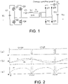
- the circuit structure of LLC resonant converter includes: an input filter capacitor C i , an inverter bridge composed of four switch tubes ( Q 1 Q 2 Q 3 Q 4 ), a resonant inductor L r , a resonant capacitor C r , a transformer T, a rectifier circuit composed of four diodes ( D 1 D 2 D 3 D 4 ) and an output filter capacitor C o .
- the output current i d of the LLC resonant converter At the end of the rectifier circuit (such as the sampling point S shown in FIG. 1 ) is the output current i d of the LLC resonant converter.
- the LLC resonant converter operates in the operating interval of t s > t r .
- the LLC resonant converter After injecting the driving current into the LLC resonant converter shown in FIG. 1 , the LLC resonant converter starts to operate.
- the waveform diagrams of the switching signal, resonant current i r , exiting current i m and the output current i d at the end of the rectifier circuit is as shown in FIG. 2 .
- the resonant angular velocity ⁇ r of the three mentioned above is much smaller than the resonant angular velocity in the period t 0 - t 1 . Therefore, the resonant current i r and exciting current i m are approximately unchanged under the circumstances.
- the disclosure provides a current detection method and device for LLC resonant converter.
- the overall idea is that based on the operating principle of LLC resonant converter, the output current expression of LLC resonant converter is transformed through theoretical derivation, so that only one current sampling is required, and combining with the known conditions in the LLC resonant converter, it is possible to solve the current waveform of the output current of the LLC resonant converter in various switching periods.
- the disclosure makes the following derivation based on the operating principle of LLC resonant converter.
- u C and u L respectively represent the voltages of the resonant capacitor C r and the resonant inductor L r
- V i represents the input voltage of the LLC resonant converter
- V o represents the output voltage of the LLC resonant converter
- N represents the turns ratio between the primary side and the secondary side of the transformer T.
- exciting current i m t NV o 4 t ⁇ t r 4 L m .
- the exciting current is only related to known parameters such as the structure parameters and output voltage of the LLC resonant converter.
- . Since the resonant current at the moment t 0 is equal to the exciting current, i r ( t 0 ) i m ( t 0 ) .
- the waveform changes of the exciting current i m (t) and the resonant current i r (t) have the same size and opposite direction as compared with the time period t 0 - t 1 .
- the waveform change of the output current i d ( t ) is the same as the time period t 0 - t 1 .
- i m t ⁇ NV o 4 t ⁇ t r 4 L m
- i r t ⁇ I r 1 sin 2 ⁇ t t r ⁇ I r 2 cos 2 ⁇ t t r
- i d ( t ) N
- i r ( t 3 ) i m ( t 3 )
- the two equations are combined, and the two variables I r 1 and I r 2 can be calculated. In this way, the waveform expression of i d ( t ) in this switching period can be calculated.
- a current detection method of LLC resonant converter includes the following.
- a resonant current i r of the LLC resonant converter is decomposed into a superposed form of a sine component and a cosine component.
- the output current i d of the LLC resonant converter is arranged into an expression i d ( t ) of the resonant current i r and an exciting current i m of the LLC resonant converter.
- the output current i d is sampled once at any moment t' in a half resonant period, thereby obtaining a sampled current value i d (t'). In this way, a relation between the resonant current i r and the exciting current i m at the moment t' is obtained.
- the relation that the resonant current i r and the exciting current i m are equal at the starting moment of the half resonant period are combined with the relation between the resonant current i r and the exciting current i m at the moment t'.
- the relation equations are solved to obtain amplitudes of a sine component and a cosine component of the resonant current i r , the amplitudes are substituted into the expression i d ( t ) to obtain a waveform expression of the output current i d at the end of the rectifier circuit of the LLC resonant converter in the switching period that belongs to the half resonant period.
- the half resonant period for sampling the output current is the first half resonant period in a switching period, that is, the time period t 0 - t 1 shown in FIG. 2 .
- the current sampling point is the end of the rectifier circuit of the LLC resonant converter, that is, the current sampling point S in FIG. 1 .
- the transient load of the LLC resonant converter in this period can be derived.
- this embodiment further includes the following.
- the peak value and/or effective value of the output current i d in the corresponding switching period are calculated.
- this embodiment can instantly calculate the real-time output current of various switching periods when the LLC converter is operated in the high-frequency condition through a single acquisition of transient currents and theoretical analysis, thereby improving the dynamic characteristics and response speed of the control algorithm of the LLC converter, which helps to precisely control the LLC resonant converter operating under high-frequency condition.
- Second embodiment A current detection method for an LLC resonant converter. This embodiment is similar to the first embodiment above, except that in this embodiment, the half resonant period during which the output current is sampled is the second half resonant period within a switching period, that is, the time period t 3 - t 4 shown in FIG. 2 .
- the transient load of the LLC resonant converter in this period can be derived.
- a current detection device of LLC resonant converter includes a sampling unit and a calculation unit.
- the calculation unit is used to decompose the resonant current i r of the LLC resonant converter into the superposed form of the sine component and cosine component, and then arrange the output current i d of the LLC resonant converter into the expression i d ( t ) of the resonant current i r and the exciting current i m of the LLC resonant converter.
- the sampling unit is used to sample the output current i d once at any moment t' in the half resonant period during the operation of the LLC resonant converter to obtain the sampled current value i d (t'), thereby obtaining the relation between the resonant current i r and the exciting current i m at the moment t'.
- the sampling unit may be a current sampling chip whose sampling speed matches the switching frequency.
- the calculation unit is further used to combine the relation that the resonant current i r and the exciting current i m are equal at the starting moment of the half resonant period with the relation between the resonant current i r and the exciting current i m at the moment t', solve the equations to obtain amplitudes of the sine component and the cosine component of the resonant current i r , substitute the amplitudes into the expression i d ( t ) to obtain a waveform expression of the output current i d at the end of the rectifier circuit of the LLC resonant converter in the switching period that belongs to the half resonant period.
Landscapes
- Engineering & Computer Science (AREA)
- Power Engineering (AREA)
- Physics & Mathematics (AREA)
- General Physics & Mathematics (AREA)
- Dc-Dc Converters (AREA)
Abstract
Description
- The disclosure belongs to the technical field of switching power supplies of power electronics, and more specifically, relates to a current detection method and device of an LLC resonant converter.
- In order to adapt to the trend of miniaturization of switching power supplies, power semiconductor devices have been developed with high frequency, because for switching power supplies, the most effective way to reduce the size and increase the power density is to increase the switching frequency. In recent years, the third-generation wide-bandgap semiconductors can greatly improve the performance of power supply devices because of their extraordinary characteristics such as high switching frequency and low driving loss. Therefore, they have been widely adopted in the field of switching power supplies. Since LLC resonant converters can achieve soft switching in the full load range to reduce switching losses, the structure is simple and efficient, and is very compatible with the characteristics of third-generation semiconductors, LLC resonant converters using third-generation semiconductors have become a popular topic for research.
- No matter in the case of precise closed-loop control of a single-phase LLC resonant converter or precise current sharing control of a multi-phase LLC resonant converter, accurate and fast current feedback information is required. With the application and promotion of third-generation semiconductors, the switching frequency of LLC resonant converters has increased to hundreds of kHz or even MHz level, and the output current waveform of the rectifier circuit on the secondary side of the transformer when the LLC resonant converter is operating is twice the half-wave waveform of the switching frequency, and the amplitude of current ripple is large. The ultra-high switching frequency and the characteristics of LLC itself make it difficult for ordinary current detection methods to obtain accurate and instant output current information of LLC resonant converters, that is, it is difficult to acquire the transient load of LLC resonant converters. Therefore, it is a challenge to carry out precise control of the LLC resonant converter which operates under high frequency and current sharing control of the interleaved parallel LLC resonant converter.
- Before the popularization and application of third-generation semiconductors, the switching frequency of LLC resonant converters was generally low. In order to obtain current information when the converter is operating, the converter is usually sampled with high frequency current 5-10 times per period, thereby estimating the current waveform of each period. In occasions where there is no high requirement for instant current information, it is also possible to perform low-pass filtering and sampling of the high-frequency half-wave current through the low-pass filter circuit, thereby estimating the actual waveform through the sampled low-pass current value. However, clearly the problem with such method is that the dynamic characteristics are poor, and there is hysteresis in current sampling, which will have a negative impact on algorithms that require high dynamic characteristics, especially when the operation condition of converter is unstable.
- In view of the defects and requirements of improvement of conventional technology, the disclosure provides a current detection method and device for LLC resonant converter, which aims to solve the technical problem that the existing current detection methods of high-frequency LLC resonant converter cannot accurately obtain the current information of LLC resonant converter in real time.
- In order to achieve the above purpose, according to one aspect of the disclosure, a current detection method of LLC resonant converter is provided, which includes:
- A resonant current ir of the LLC resonant converter is decomposed into a superposed form of a sine component and a cosine component. The output current id of the LLC resonant converter is arranged into an expression id (t) of the resonant current ir and an exciting current im of the LLC resonant converter.
- In the operation process of the LLC resonant converter, the output current id is sampled once at any moment t' in a half resonant period, thereby obtaining a sampled current value id (t'). In this way, a relation between the resonant current ir and the exciting current im at the moment t' is obtained.
- The relation that the resonant current ir and the exciting current im are equal at the starting moment of the half resonant period are combined with the relation between the resonant current ir and the exciting current im at the moment t'. The relation equations are solved to obtain amplitudes of a sine component and a cosine component of the resonant current ir , the amplitudes are substituted into the expression id (t) to obtain a waveform expression of the output current id of the LLC resonant converter in the switching period that belongs to the half resonant period.
- The disclosure decomposes the resonant current ir of the LLC resonant converter into a superposed form of a sine component and a cosine component, so that the expression of the resonant current ir only contains two unknown quantities, namely the sine component amplitude and the cosine component amplitude. After the output current id is arranged into the expression id (t) of the resonant current ir and the exciting current im of the LLC resonant converter, since the exciting current im is only related to the known parameters such as the structure parameters and output voltage of the LLC resonant converter, there are still only two unknown quantities in the expression id (t). Since the resonant current ir and the exciting current im are in an equal relationship at the starting moment of the half resonant period, it is only necessary to sample the output current id once to obtain the relation between the resonant current ir and the exciting current im at another moment. By combining the two relation equations, the two unknown quantities in the equation of the output voltage can be solved, thereby obtaining the waveform expression of the output current id (t) in the corresponding switching period. In the disclosure, there is no need to perform multiple times of sampling in the process of detecting the current of the LLC resonant converter, and there is no complicated fitting process. In this way, the disclosure can realize instant and accurate current detection and improve the dynamic performance of the subsequent control algorithm.
- Further, after arranging the output current id of the LLC resonant converter into the expression id (t) of the resonant current ir and the exciting current im of the LLC resonant converter, the expression id (t) is as follows.

- In the expression, N represents the turns ratio between the primary side and the secondary side of the transformer in the LLC resonant converter, and t represents the time variable.
- In some alternative embodiments, the half resonant period during which the output current id is sampled is the first half resonant period in one switching period.
- Further, after decomposing the resonant current ir of the LLC resonant converter into the superposed form of the sine component and cosine component, the expression of the resonant current ir is as follows.

- In the expression, I r1 and I r2 respectively represent the amplitudes of the sine component and cosine component of the resonant current after decomposition, tr represents the resonant period of the LLC resonant converter, and t represents the time variable.
- Further, the expression for the exciting current im of the LLC resonant converter is as follows.

- In the expression, N represents the turns ratio between the primary side and the secondary side of the transformer in the LLC resonant converter, Vo represents the output voltage of the LLC resonant converter, tr represents the resonant period of the LLC resonant converter, Lm represents the magnetizing inductance of the transformer in the LLC resonant converter, and t represents the time variable.
- In some alternative embodiments, the half resonant period during which the output current id is sampled is the second half resonant period in one switching period.
- Further, after decomposing the resonant current ir of the LLC resonant converter into the superposed form of the sine component and cosine component, the expression of the resonant current ir is as follows.

- In the expression, I r1 and I r2 respectively represent the amplitudes of the sine component and cosine component of the resonant current after decomposition, tr represents the resonant period of the LLC resonant converter, and t represents the time variable.
- Further, the expression for the exciting current im of the LLC resonant converter is as follows.

- In the expression, N represents the turns ratio between the primary side and the secondary side of the transformer in the LLC resonant converter, Vo represents the output voltage of the LLC resonant converter, tr represents the resonant period of the LLC resonant converter, Lm represents the magnetizing inductance of the transformer in the LLC resonant converter, and t represents the time variable.
- Further, the current detection method of LLC resonant converter provided by the disclosure further includes the following.
- A waveform expression of the output current id of the LLC resonant converter in the switching period that belongs to the half resonant period is used to calculate the peak value and/or effective value of the output current id in the corresponding switching period.
- According to another aspect of the disclosure, a current detection device of an LLC resonant converter is provided, including: a sampling unit and a calculation unit.
- The calculation unit is used to decompose the resonant current ir of the LLC resonant converter into the superposed form of the sine component and cosine component, and then arrange the output current id of the LLC resonant converter into the expression id (t) of the resonant current ir and the exciting current im of the LLC resonant converter.
- The sampling unit is used to sample the output current id once at any moment t' in the half resonant period during the operation of the LLC resonant converter to obtain the sampled current value id (t'), thereby obtaining the relation between the resonant current ir and the exciting current im at the moment t'.
- The calculation unit is further used to combine the relation that the resonant current ir and the exciting current im are equal at the starting moment of the half resonant period with the relation between the resonant current ir and the exciting current im at the moment t', solve the equations to obtain amplitudes of the sine component and the cosine component of the resonant current ir , substitute the amplitudes into the expression id (t) to obtain a waveform expression of the output current id of the LLC resonant converter in the switching period that belongs to the half resonant period.
- In general, through the above technical solutions conceived in the disclosure, the following advantageous effects can be achieved.
- (1) Through a single acquisition of transient current and theoretical analysis, the disclosure can instantly calculate the real-time output current in each switching period when the LLC converter is operated under high frequency. In this way, the dynamic characteristics and response speed of the control algorithm of LLC converter can be improved, which helps to precisely control the LLC resonant converter under high-frequency operating conditions.
- (2) The disclosure only needs to sample a current sampling chip whose sampling speed matches the LLC switching frequency, thereby realizing sampling of a single transient current and completing current detection without adding a complicated sampling circuit. The requirement for hardware is low, and the cost is low as well.
-
-
FIG. 1 is a schematic diagram of the structure of an existing LLC resonant converter. -
FIG. 2 is a schematic waveform diagram of the switching signal, resonant current ir , exiting current im and the output current id at the end of the rectifier circuit of the existing LLC resonant converter; wherein (a) is a schematic waveform diagram of the switching signal of the LLC resonant converter, (b) is a schematic waveform diagram of the resonant current ir and the exiting current im of the LLC resonant converter, and (c) is a schematic waveform diagram of the output current id at the end of the rectifier circuit of the LLC resonant converter. -
FIG. 3 is a schematic diagram of a current detection method of an LLC resonant converter provided by an embodiment of the disclosure. - In order to make the objectives, technical solutions, and advantages of the present disclosure clearer, the following further describes the present disclosure in detail with reference to the accompanying drawings and embodiments. It should be understood that the specific embodiments described here are only used to explain the present disclosure, but not used to limit the present disclosure. In addition, the technical features involved in the various embodiments of the present disclosure described below can be combined with each other as long as they do not conflict with each other.
- In the present disclosure, the terms "first", "second", etc. (if any) in the present disclosure and the accompanying drawings are used to distinguish similar objects, and are not necessarily used to describe a specific sequence or order.
- Before explaining the technical scheme of the present disclosure in detail, the structure of the LLC resonant converter and its operating principle will be briefly introduced as follows.
- The structure of LLC resonant converter is shown in
FIG. 1 . The circuit structure of LLC resonant converter includes: an input filter capacitor Ci , an inverter bridge composed of four switch tubes (Q 1 Q 2 Q 3 Q 4), a resonant inductor Lr , a resonant capacitor Cr , a transformer T, a rectifier circuit composed of four diodes (D 1 D 2 D 3 D 4) and an output filter capacitor C o. At the end of the rectifier circuit (such as the sampling point S shown inFIG. 1 ) is the output current id of the LLC resonant converter. - The duration of one switching period of the LLC resonant converter is ts = 2t 2, and the resonant period of the LLC resonant converter is ts = 2t 2. In the following embodiments, the LLC resonant converter operates in the operating interval of ts > tr. The expression of the resonant period tr is specifically

- After injecting the driving current into the LLC resonant converter shown in
FIG. 1 , the LLC resonant converter starts to operate. During operation, the waveform diagrams of the switching signal, resonant current ir , exiting current im and the output current id at the end of the rectifier circuit is as shown inFIG. 2 . - As shown in (a) of
FIG. 2 , at time t 0, that is, at the starting moment of a switching period (the starting moment of the first half of the resonant period), the switching tubes Q 1 and Q 4 are turned on. Since the resonant current ir before turning on is less than 0, Q 1 and Q 4 are in the reverse-conducting freewheeling state, so the voltages at both ends of Q 1 and Q 4 are in the clamp state. As such, Q 1 and Q 4 can be zero-voltage-switching (ZVS) at the moment t 0 The resonant current ir flows through Q 1 and Q 4 , Lr and Cr begin to resonate. Because the transformer is clamped by the secondary side, the exciting current im rises approximately linearly. The voltage direction on the secondary side of the transformer is positive and negative, and the current flows through the rectifier diodes D 1 and D 4 to supply energy for the load. - As shown in (b) of
FIG. 2 , at the moment t 1, at the end of the first half of the resonant period, the resonant current ir is equal to the exciting current im , so the energy exchange between the primary side and the secondary side of the transformer is disconnected, and the current on the secondary side drops rapidly to 0. Then, the rectifier diodes D 1 and D 4 achieve zero current switching, and the current at the secondary side io =0. Due to the turn-off of the rectifier circuit, the clamping of the primary side of the transformer is eliminated. Under the circumstances, the magnetizing inductance Lm and the resonant inductance Lr of the transformer resonate together with the resonant capacitor Cr to generate resonance. Because the magnetizing inductance Lm of the transformer is far greater than the resonant inductance Lr , the resonant angular velocity ωr of the three mentioned above is much smaller than the resonant angular velocity in the period t 0 - t 1 . Therefore, the resonant current ir and exciting current im are approximately unchanged under the circumstances. - Because the existing current detection method for LLC resonant converter needs to carry out sampling for multiple times and estimate the current waveform of various switching periods based on the sampling results, it is difficult to accurately and instantly detect the current of LLC resonant converter operating in high-frequency condition. To solve the above problem, the disclosure provides a current detection method and device for LLC resonant converter. The overall idea is that based on the operating principle of LLC resonant converter, the output current expression of LLC resonant converter is transformed through theoretical derivation, so that only one current sampling is required, and combining with the known conditions in the LLC resonant converter, it is possible to solve the current waveform of the output current of the LLC resonant converter in various switching periods.
- Based on the above ideas, the disclosure makes the following derivation based on the operating principle of LLC resonant converter.
- uC and uL respectively represent the voltages of the resonant capacitor Cr and the resonant inductor Lr , and I 1,ini and V 1,ini respectively represent the initial values of the resonant current ir and voltage uC at the moment t 0, that is,

- Because


- Exciting current
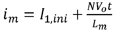
- In the expression, Vi represents the input voltage of the LLC resonant converter, Vo represents the output voltage of the LLC resonant converter, and N represents the turns ratio between the primary side and the secondary side of the transformer T.
- Since the resonant current ir and exciting current im are approximately unchanged during the time period t 0 - t 1, it is known that in the time period t 0 - t 1, im (t) = ir (t) = im (t 1) = ir (t 1). As shown in
FIG. 2(b) , the waveform changes in the time period t 3 - t 4 (that is, in the second half of the resonant period) have the same size and opposite direction compared with the time period t 0 - t 1, that is, im (t 3) = ir (t 3) = im (t 0) = ir (t 0) = -I 1,ini , that is,
- Based on the above analysis, it can be obtained through calculation that in the time period t 0 - t 1, exciting current

- Assume

- The two equations are combined to calculate the two variables I r1 and I r2 in

- In the time period t 3 - t 4 (that is, in the second half of the resonant period), the waveform changes of the exciting current im (t) and the resonant current ir (t) have the same size and opposite direction as compared with the time period t 0 - t 1 . As shown in
FIG. 2(c), in the time period t 3 - t 4, the waveform change of the output current id (t) is the same as the time period t 0 - t 1 . Therefore, in the time period t 3 - t 4,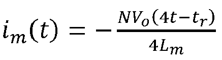

- The following are embodiments.
- First embodiment:
A current detection method of LLC resonant converter, as shown inFIG. 3 , includes the following. - A resonant current ir of the LLC resonant converter is decomposed into a superposed form of a sine component and a cosine component. The output current id of the LLC resonant converter is arranged into an expression id (t) of the resonant current ir and an exciting current im of the LLC resonant converter.
- In the operation process of the LLC resonant converter, the output current id is sampled once at any moment t' in a half resonant period, thereby obtaining a sampled current value id (t'). In this way, a relation between the resonant current ir and the exciting current im at the moment t' is obtained.
- The relation that the resonant current ir and the exciting current im are equal at the starting moment of the half resonant period are combined with the relation between the resonant current ir and the exciting current im at the moment t'. The relation equations are solved to obtain amplitudes of a sine component and a cosine component of the resonant current ir , the amplitudes are substituted into the expression id (t) to obtain a waveform expression of the output current id at the end of the rectifier circuit of the LLC resonant converter in the switching period that belongs to the half resonant period.
- In this embodiment, the half resonant period for sampling the output current is the first half resonant period in a switching period, that is, the time period t 0 - t 1 shown in
FIG. 2 . The current sampling point is the end of the rectifier circuit of the LLC resonant converter, that is, the current sampling point S inFIG. 1 . - In the embodiment,

is combined with

- The two equations are solved to obtain the amplitudes I r1 and I r2 of the sine component and cosine component of the resonant current ir , and the amplitudes are substituted into the expression id (t) to obtain that the waveform expression of the output current of the LLC resonant converter in a switching period is as follows.

- Based on the waveform expression of the output current of the LLC resonant converter in a switching period, the transient load of the LLC resonant converter in this period can be derived.
- As an alternative implementation manner, this embodiment further includes the following.
- According to the waveform expression of the output current id at the end of the rectifier circuit in the LLC resonant converter in the switching period that belongs to the half resonant period, the peak value and/or effective value of the output current id in the corresponding switching period are calculated.
- In general, this embodiment can instantly calculate the real-time output current of various switching periods when the LLC converter is operated in the high-frequency condition through a single acquisition of transient currents and theoretical analysis, thereby improving the dynamic characteristics and response speed of the control algorithm of the LLC converter, which helps to precisely control the LLC resonant converter operating under high-frequency condition.
- Second embodiment:
A current detection method for an LLC resonant converter. This embodiment is similar to the first embodiment above, except that in this embodiment, the half resonant period during which the output current is sampled is the second half resonant period within a switching period, that is, the time period t 3 - t 4 shown inFIG. 2 . - In the embodiment,

is combined with

- The two equations are solved to obtain the amplitudes I r1 and I r2 of the sine component and cosine component of the resonant current ir , and the amplitudes are substituted into the expression id (t) to obtain that the waveform expression of the output current of the LLC resonant converter in a switching period is as follows.

- Based on the waveform expression of the output current of the LLC resonant converter in a switching period, the transient load of the LLC resonant converter in this period can be derived.
- Third embodiment:
A current detection device of LLC resonant converter includes a sampling unit and a calculation unit. - The calculation unit is used to decompose the resonant current ir of the LLC resonant converter into the superposed form of the sine component and cosine component, and then arrange the output current id of the LLC resonant converter into the expression id (t) of the resonant current ir and the exciting current im of the LLC resonant converter.
- The sampling unit is used to sample the output current id once at any moment t' in the half resonant period during the operation of the LLC resonant converter to obtain the sampled current value id (t'), thereby obtaining the relation between the resonant current ir and the exciting current im at the moment t'. The sampling unit may be a current sampling chip whose sampling speed matches the switching frequency.
- The calculation unit is further used to combine the relation that the resonant current ir and the exciting current im are equal at the starting moment of the half resonant period with the relation between the resonant current ir and the exciting current im at the moment t', solve the equations to obtain amplitudes of the sine component and the cosine component of the resonant current ir , substitute the amplitudes into the expression id (t) to obtain a waveform expression of the output current id at the end of the rectifier circuit of the LLC resonant converter in the switching period that belongs to the half resonant period.
- In this embodiment, for the specific implementation of each module, please refer to the description in the above method embodiment, and no further description is incorporated herein.
- Those skilled in the art can easily understand that the above are only preferred embodiments of the present disclosure and are not intended to limit the present disclosure. Any modification, equivalent replacement and improvement, etc. made within the spirit and principle of the present disclosure should fall within the scope to be protected by the present disclosure.
Claims (10)
- A current detection method of an LLC resonant converter, characterized in comprising:decomposing a resonant current ir of the LLC resonant converter into a superposed form of a sine component and a cosine component, arranging an output current id of the LLC resonant converter into an expression id (t) of the resonant current ir and an exciting current im of the LLC resonant converter; in an operation process of the LLC resonant converter, sampling the output current id once at any moment t' in a half resonant period, thereby obtaining a sampled current value id (t'), thereby obtaining a relation between the resonant current ir and the exciting current im at the moment t';combining a relation that the resonant current ir and the exciting current im are equal at a starting moment of the half resonant period with the relation between the resonant current ir and the exciting current im at the moment t', solving the relation equations to obtain amplitudes of the sine component and the cosine component of the resonant current ir , substituting the amplitudes into the expression id (t) to obtain a waveform expression of the output current id of the LLC resonant converter in a switching period that belongs to the half resonant period.
- The current detection method of the LLC resonant converter according to claim 1, characterized in that after arranging the output current id of the LLC resonant converter into the expression id (t) of the resonant current ir and the exciting current im of the LLC resonant converter, the expression id (t) is as follows:

- The current detection method of the LLC resonant converter according to claim 1 or 2, characterized in that the half resonant period during which the output current id is sampled is a first half resonant period in one switching period.
- The current detection method of the LLC resonant converter according to claim 3, wherein after decomposing the resonant current ir of the LLC resonant converter into the superposed form of the sine component and cosine component, the expression of the resonant current ir is as follows:

- The current detection method of the LLC resonant converter according to claim 3, characterized in that the expression for the exciting current im of the LLC resonant converter is as follows:

- The current detection method of the LLC resonant converter according to claim 1 or 2, characterized in that the half resonant period during which the output current id is sampled is a second half resonant period in one switching period.
- The current detection method of the LLC resonant converter according to claim 6, characterized in that after decomposing the resonant current ir of the LLC resonant converter into the superposed form of the sine component and cosine component, the expression of the resonant current ir is as follows:

- The current detection method of the LLC resonant converter according to claim 6, characterized in that the expression for the exciting current im of the LLC resonant converter is as follows:

- The current detection method of the LLC resonant converter according to claim 1 or 2, characterized in further comprising:
the waveform expression of the output current id of the LLC resonant converter in the switching period that belongs to the half resonant period is used to calculate a peak value and/or an effective value of the output current id in a corresponding switching period. - A current detection device of an LLC resonant converter, characterized in comprising: a sampling unit and a calculation unit;wherein the calculation unit is used to decompose a resonant current ir of the LLC resonant converter into a superposed form of a sine component and cosine component, and arrange an output current id of the LLC resonant converter into an expression id (t) of the resonant current ir and an exciting current im of the LLC resonant converter;the sampling unit is used to sample the output current id once at any moment t' in a half resonant period during an operation process of the LLC resonant converter to obtain a sampled current value id (t'), thereby obtaining a relation between the resonant current ir and the exciting current im at the moment t';the calculation unit is further used to combine a relation that the resonant current ir and the exciting current im are equal at a starting moment of the half resonant period with the relation between the resonant current ir and the exciting current im at the moment t', solve the relation equations to obtain amplitudes of the sine component and the cosine component of the resonant current ir , substitute the amplitudes into the expression id (t) to obtain a waveform expression of the output current id of the LLC resonant converter in a switching period that belongs to the half resonant period.
Applications Claiming Priority (2)
| Application Number | Priority Date | Filing Date | Title |
|---|---|---|---|
| CN202010699920.2A CN111884515B (en) | 2020-07-20 | 2020-07-20 | A kind of current detection method and device of LLC resonant converter |
| PCT/CN2021/072339 WO2022016835A1 (en) | 2020-07-20 | 2021-01-16 | Current measurement method and apparatus for llc resonant converter |
Publications (2)
| Publication Number | Publication Date |
|---|---|
| EP4012911A1 true EP4012911A1 (en) | 2022-06-15 |
| EP4012911A4 EP4012911A4 (en) | 2022-11-16 |
Family
ID=73156178
Family Applications (1)
| Application Number | Title | Priority Date | Filing Date |
|---|---|---|---|
| EP21845927.9A Pending EP4012911A4 (en) | 2020-07-20 | 2021-01-16 | METHOD AND DEVICE FOR CURRENT MEASUREMENT FOR A LLC RESONANCE CONVERTER |
Country Status (3)
| Country | Link |
|---|---|
| EP (1) | EP4012911A4 (en) |
| CN (1) | CN111884515B (en) |
| WO (1) | WO2022016835A1 (en) |
Families Citing this family (2)
| Publication number | Priority date | Publication date | Assignee | Title |
|---|---|---|---|---|
| CN111884515B (en) * | 2020-07-20 | 2021-07-27 | 华中科技大学 | A kind of current detection method and device of LLC resonant converter |
| CN119471431B (en) * | 2025-01-17 | 2025-03-28 | 深圳市尚科新能源有限公司 | Calculation method of battery current in llc topology |
Family Cites Families (10)
| Publication number | Priority date | Publication date | Assignee | Title |
|---|---|---|---|---|
| EP2299580A3 (en) * | 2009-06-24 | 2011-07-27 | STMicroelectronics S.r.l. | Multi-phase resonant converter and method of controlling it |
| TWI568166B (en) * | 2015-11-26 | 2017-01-21 | A High Efficiency LLC Resonant Converter with Secondary Side Synchronous Rectifier Blind Control | |
| CN107769563B (en) * | 2016-08-17 | 2020-03-24 | 英飞特电子(杭州)股份有限公司 | Resonant converter |
| KR102009351B1 (en) * | 2017-12-18 | 2019-08-12 | 순천향대학교 산학협력단 | High Efficiency LLC Resonant Converter with Balanced Secondary Currents using the Two Transformer Structure |
| CN108418433A (en) * | 2018-03-29 | 2018-08-17 | 深圳驿普乐氏科技有限公司 | A kind of LLC resonant converter and its control circuit, resonant current sampling circuit |
| CN210469803U (en) * | 2018-09-11 | 2020-05-05 | 杭州电子科技大学 | Primary side constant current control device |
| CN109639151B (en) * | 2019-01-21 | 2024-11-15 | 杭州士兰微电子股份有限公司 | Constant current control circuit and constant current control method for LLC resonant converter |
| CN109842302B (en) * | 2019-02-15 | 2020-08-14 | 矽力杰半导体技术(杭州)有限公司 | Series resonant converter and primary side feedback control circuit and control method thereof |
| CN110112926B (en) * | 2019-06-05 | 2021-04-09 | 南京航空航天大学 | A Resonant Converter Current Detection and Control Method |
| CN111884515B (en) * | 2020-07-20 | 2021-07-27 | 华中科技大学 | A kind of current detection method and device of LLC resonant converter |
-
2020
- 2020-07-20 CN CN202010699920.2A patent/CN111884515B/en active Active
-
2021
- 2021-01-16 WO PCT/CN2021/072339 patent/WO2022016835A1/en not_active Ceased
- 2021-01-16 EP EP21845927.9A patent/EP4012911A4/en active Pending
Also Published As
| Publication number | Publication date |
|---|---|
| WO2022016835A1 (en) | 2022-01-27 |
| EP4012911A4 (en) | 2022-11-16 |
| CN111884515B (en) | 2021-07-27 |
| CN111884515A (en) | 2020-11-03 |
Similar Documents
| Publication | Publication Date | Title |
|---|---|---|
| US12609626B2 (en) | Control method for resonant dual active bridge conversion circuit, controller, and converter | |
| CN102570891B (en) | Flyback photovoltaic grid-connected inverter adopting interleaving parallel-connection active clamping technology | |
| CN113300619B (en) | Series 24-pulse Rectifier with Auxiliary Passive Pulse Multiplier | |
| CN102082436B (en) | Hybrid power filter | |
| CN110768549A (en) | A single-phase zero-voltage soft-switching charger topology and its modulation method | |
| CN102496933B (en) | Double parallel active power filtering apparatus | |
| CN108667307A (en) | LLC synchronous rectificating devices and its control method, electronic equipment, storage medium | |
| CN112260549B (en) | Method for reducing inverter loss on primary side of resonant wireless power transfer system | |
| CN113949276A (en) | Control system and control method of double-clamping zero-voltage switch converter | |
| CN114966214A (en) | Broadband harmonic disturbance device and control method | |
| CN102916604B (en) | One-phase inverter modulation method | |
| Ren et al. | A digital sensor-less synchronous rectification algorithm for symmetrical bidirectional CLLC resonant converters | |
| CN117411286B (en) | A power transformer double frequency current suppression circuit and suppression method | |
| Luo et al. | Current balancing control method with reduced number of current sensors for interleaved LLC converters | |
| WO2022016835A1 (en) | Current measurement method and apparatus for llc resonant converter | |
| Li et al. | A novel 16PIM energy modulation method for simultaneous wireless power and data transfer system | |
| Chen et al. | A novel three level full bridge resonant DC-DC converter suitable for high power wide range input applications | |
| CN114499197B (en) | Optimization Method and System for Resonant Converters Based on fmincon Function | |
| Wang et al. | Comprehensive analysis of Buck mode frozen leg operation for three-phase dual active bridge converters | |
| Zhang et al. | The model of bidirectional CLLC resonant converter with variable frequency and single phase shifted control | |
| Luan et al. | Design of a Secondary Side Auxiliary Compensator for Current-Sharing Control of Input-Parallel OutputParallel Phase-Shifted Full-Bridge Converters | |
| CN111865113B (en) | Series 48-pulse rectifier using DC side mixed harmonic suppression method | |
| Feng et al. | Design of high-voltage DC power supply based on series-resonant constant-current charging | |
| CN114710044A (en) | Flyback converter and constant current control method thereof | |
| Liu et al. | A secondary‐side semi‐active series resonant converter employing hybrid modulation scheme for on‐board chargers |
Legal Events
| Date | Code | Title | Description |
|---|---|---|---|
| STAA | Information on the status of an ep patent application or granted ep patent |
Free format text: STATUS: THE INTERNATIONAL PUBLICATION HAS BEEN MADE |
|
| PUAI | Public reference made under article 153(3) epc to a published international application that has entered the european phase |
Free format text: ORIGINAL CODE: 0009012 |
|
| STAA | Information on the status of an ep patent application or granted ep patent |
Free format text: STATUS: REQUEST FOR EXAMINATION WAS MADE |
|
| 17P | Request for examination filed |
Effective date: 20220308 |
|
| AK | Designated contracting states |
Kind code of ref document: A1 Designated state(s): AL AT BE BG CH CY CZ DE DK EE ES FI FR GB GR HR HU IE IS IT LI LT LU LV MC MK MT NL NO PL PT RO RS SE SI SK SM TR |
|
| A4 | Supplementary search report drawn up and despatched |
Effective date: 20221018 |
|
| RIC1 | Information provided on ipc code assigned before grant |
Ipc: H02M 3/00 20060101ALI20221012BHEP Ipc: H02M 1/00 20060101ALI20221012BHEP Ipc: G01R 19/00 20060101ALI20221012BHEP Ipc: H02M 3/335 20060101AFI20221012BHEP |
|
| RIC1 | Information provided on ipc code assigned before grant |
Ipc: H02M 3/00 20060101ALI20221107BHEP Ipc: H02M 1/00 20060101ALI20221107BHEP Ipc: G01R 19/00 20060101ALI20221107BHEP Ipc: H02M 3/335 20060101AFI20221107BHEP |
|
| STAA | Information on the status of an ep patent application or granted ep patent |
Free format text: STATUS: EXAMINATION IS IN PROGRESS |
|
| 17Q | First examination report despatched |
Effective date: 20230425 |
|
| DAV | Request for validation of the european patent (deleted) | ||
| DAX | Request for extension of the european patent (deleted) |