EP4012831A1 - Battery - Google Patents
Battery Download PDFInfo
- Publication number
- EP4012831A1 EP4012831A1 EP20850393.8A EP20850393A EP4012831A1 EP 4012831 A1 EP4012831 A1 EP 4012831A1 EP 20850393 A EP20850393 A EP 20850393A EP 4012831 A1 EP4012831 A1 EP 4012831A1
- Authority
- EP
- European Patent Office
- Prior art keywords
- current collector
- plate
- positive electrode
- sealing plate
- negative electrode
- Prior art date
- Legal status (The legal status is an assumption and is not a legal conclusion. Google has not performed a legal analysis and makes no representation as to the accuracy of the status listed.)
- Pending
Links
- 238000007789 sealing Methods 0.000 claims abstract description 120
- 238000003466 welding Methods 0.000 claims abstract description 53
- 238000009421 internal insulation Methods 0.000 claims description 29
- 239000010410 layer Substances 0.000 description 17
- 229910052751 metal Inorganic materials 0.000 description 17
- 239000002184 metal Substances 0.000 description 17
- 239000000203 mixture Substances 0.000 description 17
- 239000002002 slurry Substances 0.000 description 14
- 239000003792 electrolyte Substances 0.000 description 13
- 238000003780 insertion Methods 0.000 description 12
- 230000037431 insertion Effects 0.000 description 12
- 239000007774 positive electrode material Substances 0.000 description 12
- 238000000034 method Methods 0.000 description 11
- 239000007773 negative electrode material Substances 0.000 description 10
- 239000011241 protective layer Substances 0.000 description 9
- 229920005989 resin Polymers 0.000 description 9
- 239000011347 resin Substances 0.000 description 9
- 238000009422 external insulation Methods 0.000 description 8
- -1 particularly Inorganic materials 0.000 description 8
- 239000000843 powder Substances 0.000 description 7
- SECXISVLQFMRJM-UHFFFAOYSA-N N-Methylpyrrolidone Chemical compound CN1CCCC1=O SECXISVLQFMRJM-UHFFFAOYSA-N 0.000 description 6
- 229910052782 aluminium Inorganic materials 0.000 description 6
- XAGFODPZIPBFFR-UHFFFAOYSA-N aluminium Chemical compound [Al] XAGFODPZIPBFFR-UHFFFAOYSA-N 0.000 description 6
- 229910000838 Al alloy Inorganic materials 0.000 description 5
- 239000011230 binding agent Substances 0.000 description 5
- 239000000463 material Substances 0.000 description 5
- 238000002360 preparation method Methods 0.000 description 5
- RYGMFSIKBFXOCR-UHFFFAOYSA-N Copper Chemical compound [Cu] RYGMFSIKBFXOCR-UHFFFAOYSA-N 0.000 description 4
- 239000002033 PVDF binder Substances 0.000 description 4
- 239000004743 Polypropylene Substances 0.000 description 4
- 239000006258 conductive agent Substances 0.000 description 4
- 229920001155 polypropylene Polymers 0.000 description 4
- 229920002981 polyvinylidene fluoride Polymers 0.000 description 4
- 229910000881 Cu alloy Inorganic materials 0.000 description 3
- 229910052802 copper Inorganic materials 0.000 description 3
- 239000010949 copper Substances 0.000 description 3
- 238000002347 injection Methods 0.000 description 3
- 239000007924 injection Substances 0.000 description 3
- 239000007788 liquid Substances 0.000 description 3
- 230000002093 peripheral effect Effects 0.000 description 3
- OKTJSMMVPCPJKN-UHFFFAOYSA-N Carbon Chemical compound [C] OKTJSMMVPCPJKN-UHFFFAOYSA-N 0.000 description 2
- 239000000853 adhesive Substances 0.000 description 2
- 230000001070 adhesive effect Effects 0.000 description 2
- 239000012790 adhesive layer Substances 0.000 description 2
- 230000015572 biosynthetic process Effects 0.000 description 2
- 239000003575 carbonaceous material Substances 0.000 description 2
- 239000002131 composite material Substances 0.000 description 2
- 239000011888 foil Substances 0.000 description 2
- 229910002804 graphite Inorganic materials 0.000 description 2
- 239000010439 graphite Substances 0.000 description 2
- 230000001678 irradiating effect Effects 0.000 description 2
- 238000004898 kneading Methods 0.000 description 2
- 229910021645 metal ion Inorganic materials 0.000 description 2
- 239000002244 precipitate Substances 0.000 description 2
- 239000002562 thickening agent Substances 0.000 description 2
- 229920002134 Carboxymethyl cellulose Polymers 0.000 description 1
- YCKRFDGAMUMZLT-UHFFFAOYSA-N Fluorine atom Chemical compound [F] YCKRFDGAMUMZLT-UHFFFAOYSA-N 0.000 description 1
- WHXSMMKQMYFTQS-UHFFFAOYSA-N Lithium Chemical compound [Li] WHXSMMKQMYFTQS-UHFFFAOYSA-N 0.000 description 1
- SOXUFMZTHZXOGC-UHFFFAOYSA-N [Li].[Mn].[Co].[Ni] Chemical compound [Li].[Mn].[Co].[Ni] SOXUFMZTHZXOGC-UHFFFAOYSA-N 0.000 description 1
- 239000011149 active material Substances 0.000 description 1
- PNEYBMLMFCGWSK-UHFFFAOYSA-N aluminium oxide Inorganic materials [O-2].[O-2].[O-2].[Al+3].[Al+3] PNEYBMLMFCGWSK-UHFFFAOYSA-N 0.000 description 1
- 238000007664 blowing Methods 0.000 description 1
- 239000006229 carbon black Substances 0.000 description 1
- 239000011248 coating agent Substances 0.000 description 1
- 238000000576 coating method Methods 0.000 description 1
- 239000000470 constituent Substances 0.000 description 1
- 238000007796 conventional method Methods 0.000 description 1
- 239000011889 copper foil Substances 0.000 description 1
- 239000002612 dispersion medium Substances 0.000 description 1
- 239000000428 dust Substances 0.000 description 1
- 229920001971 elastomer Polymers 0.000 description 1
- 238000007667 floating Methods 0.000 description 1
- 239000011737 fluorine Substances 0.000 description 1
- 229910052731 fluorine Inorganic materials 0.000 description 1
- 238000009413 insulation Methods 0.000 description 1
- 229910052744 lithium Inorganic materials 0.000 description 1
- 238000004519 manufacturing process Methods 0.000 description 1
- 238000012986 modification Methods 0.000 description 1
- 230000004048 modification Effects 0.000 description 1
- 238000000465 moulding Methods 0.000 description 1
- 239000011255 nonaqueous electrolyte Substances 0.000 description 1
- 239000004745 nonwoven fabric Substances 0.000 description 1
- 230000000149 penetrating effect Effects 0.000 description 1
- 239000002985 plastic film Substances 0.000 description 1
- 229920006255 plastic film Polymers 0.000 description 1
- 238000005498 polishing Methods 0.000 description 1
- 238000010248 power generation Methods 0.000 description 1
- 239000005060 rubber Substances 0.000 description 1
- 238000001179 sorption measurement Methods 0.000 description 1
- 229920003048 styrene butadiene rubber Polymers 0.000 description 1
- XLYOFNOQVPJJNP-UHFFFAOYSA-N water Substances O XLYOFNOQVPJJNP-UHFFFAOYSA-N 0.000 description 1
Images


Classifications
-
- H—ELECTRICITY
- H01—ELECTRIC ELEMENTS
- H01M—PROCESSES OR MEANS, e.g. BATTERIES, FOR THE DIRECT CONVERSION OF CHEMICAL ENERGY INTO ELECTRICAL ENERGY
- H01M50/00—Constructional details or processes of manufacture of the non-active parts of electrochemical cells other than fuel cells, e.g. hybrid cells
- H01M50/10—Primary casings, jackets or wrappings of a single cell or a single battery
- H01M50/172—Arrangements of electric connectors penetrating the casing
- H01M50/174—Arrangements of electric connectors penetrating the casing adapted for the shape of the cells
- H01M50/176—Arrangements of electric connectors penetrating the casing adapted for the shape of the cells for prismatic or rectangular cells
-
- H—ELECTRICITY
- H01—ELECTRIC ELEMENTS
- H01M—PROCESSES OR MEANS, e.g. BATTERIES, FOR THE DIRECT CONVERSION OF CHEMICAL ENERGY INTO ELECTRICAL ENERGY
- H01M4/00—Electrodes
- H01M4/02—Electrodes composed of, or comprising, active material
- H01M4/64—Carriers or collectors
- H01M4/70—Carriers or collectors characterised by shape or form
-
- H—ELECTRICITY
- H01—ELECTRIC ELEMENTS
- H01M—PROCESSES OR MEANS, e.g. BATTERIES, FOR THE DIRECT CONVERSION OF CHEMICAL ENERGY INTO ELECTRICAL ENERGY
- H01M10/00—Secondary cells; Manufacture thereof
- H01M10/04—Construction or manufacture in general
-
- H—ELECTRICITY
- H01—ELECTRIC ELEMENTS
- H01M—PROCESSES OR MEANS, e.g. BATTERIES, FOR THE DIRECT CONVERSION OF CHEMICAL ENERGY INTO ELECTRICAL ENERGY
- H01M10/00—Secondary cells; Manufacture thereof
- H01M10/04—Construction or manufacture in general
- H01M10/0431—Cells with wound or folded electrodes
-
- H—ELECTRICITY
- H01—ELECTRIC ELEMENTS
- H01M—PROCESSES OR MEANS, e.g. BATTERIES, FOR THE DIRECT CONVERSION OF CHEMICAL ENERGY INTO ELECTRICAL ENERGY
- H01M10/00—Secondary cells; Manufacture thereof
- H01M10/05—Accumulators with non-aqueous electrolyte
- H01M10/052—Li-accumulators
-
- H—ELECTRICITY
- H01—ELECTRIC ELEMENTS
- H01M—PROCESSES OR MEANS, e.g. BATTERIES, FOR THE DIRECT CONVERSION OF CHEMICAL ENERGY INTO ELECTRICAL ENERGY
- H01M10/00—Secondary cells; Manufacture thereof
- H01M10/05—Accumulators with non-aqueous electrolyte
- H01M10/058—Construction or manufacture
- H01M10/0587—Construction or manufacture of accumulators having only wound construction elements, i.e. wound positive electrodes, wound negative electrodes and wound separators
-
- H—ELECTRICITY
- H01—ELECTRIC ELEMENTS
- H01M—PROCESSES OR MEANS, e.g. BATTERIES, FOR THE DIRECT CONVERSION OF CHEMICAL ENERGY INTO ELECTRICAL ENERGY
- H01M10/00—Secondary cells; Manufacture thereof
- H01M10/24—Alkaline accumulators
- H01M10/28—Construction or manufacture
-
- H—ELECTRICITY
- H01—ELECTRIC ELEMENTS
- H01M—PROCESSES OR MEANS, e.g. BATTERIES, FOR THE DIRECT CONVERSION OF CHEMICAL ENERGY INTO ELECTRICAL ENERGY
- H01M10/00—Secondary cells; Manufacture thereof
- H01M10/24—Alkaline accumulators
- H01M10/28—Construction or manufacture
- H01M10/286—Cells or batteries with wound or folded electrodes
-
- H—ELECTRICITY
- H01—ELECTRIC ELEMENTS
- H01M—PROCESSES OR MEANS, e.g. BATTERIES, FOR THE DIRECT CONVERSION OF CHEMICAL ENERGY INTO ELECTRICAL ENERGY
- H01M50/00—Constructional details or processes of manufacture of the non-active parts of electrochemical cells other than fuel cells, e.g. hybrid cells
- H01M50/10—Primary casings, jackets or wrappings of a single cell or a single battery
- H01M50/102—Primary casings, jackets or wrappings of a single cell or a single battery characterised by their shape or physical structure
- H01M50/103—Primary casings, jackets or wrappings of a single cell or a single battery characterised by their shape or physical structure prismatic or rectangular
-
- H—ELECTRICITY
- H01—ELECTRIC ELEMENTS
- H01M—PROCESSES OR MEANS, e.g. BATTERIES, FOR THE DIRECT CONVERSION OF CHEMICAL ENERGY INTO ELECTRICAL ENERGY
- H01M50/00—Constructional details or processes of manufacture of the non-active parts of electrochemical cells other than fuel cells, e.g. hybrid cells
- H01M50/10—Primary casings, jackets or wrappings of a single cell or a single battery
- H01M50/147—Lids or covers
- H01M50/148—Lids or covers characterised by their shape
- H01M50/15—Lids or covers characterised by their shape for prismatic or rectangular cells
-
- H—ELECTRICITY
- H01—ELECTRIC ELEMENTS
- H01M—PROCESSES OR MEANS, e.g. BATTERIES, FOR THE DIRECT CONVERSION OF CHEMICAL ENERGY INTO ELECTRICAL ENERGY
- H01M50/00—Constructional details or processes of manufacture of the non-active parts of electrochemical cells other than fuel cells, e.g. hybrid cells
- H01M50/10—Primary casings, jackets or wrappings of a single cell or a single battery
- H01M50/183—Sealing members
- H01M50/184—Sealing members characterised by their shape or structure
-
- H—ELECTRICITY
- H01—ELECTRIC ELEMENTS
- H01M—PROCESSES OR MEANS, e.g. BATTERIES, FOR THE DIRECT CONVERSION OF CHEMICAL ENERGY INTO ELECTRICAL ENERGY
- H01M50/00—Constructional details or processes of manufacture of the non-active parts of electrochemical cells other than fuel cells, e.g. hybrid cells
- H01M50/40—Separators; Membranes; Diaphragms; Spacing elements inside cells
- H01M50/46—Separators, membranes or diaphragms characterised by their combination with electrodes
-
- H—ELECTRICITY
- H01—ELECTRIC ELEMENTS
- H01M—PROCESSES OR MEANS, e.g. BATTERIES, FOR THE DIRECT CONVERSION OF CHEMICAL ENERGY INTO ELECTRICAL ENERGY
- H01M50/00—Constructional details or processes of manufacture of the non-active parts of electrochemical cells other than fuel cells, e.g. hybrid cells
- H01M50/50—Current conducting connections for cells or batteries
- H01M50/528—Fixed electrical connections, i.e. not intended for disconnection
-
- H—ELECTRICITY
- H01—ELECTRIC ELEMENTS
- H01M—PROCESSES OR MEANS, e.g. BATTERIES, FOR THE DIRECT CONVERSION OF CHEMICAL ENERGY INTO ELECTRICAL ENERGY
- H01M50/00—Constructional details or processes of manufacture of the non-active parts of electrochemical cells other than fuel cells, e.g. hybrid cells
- H01M50/50—Current conducting connections for cells or batteries
- H01M50/531—Electrode connections inside a battery casing
- H01M50/536—Electrode connections inside a battery casing characterised by the method of fixing the leads to the electrodes, e.g. by welding
-
- H—ELECTRICITY
- H01—ELECTRIC ELEMENTS
- H01M—PROCESSES OR MEANS, e.g. BATTERIES, FOR THE DIRECT CONVERSION OF CHEMICAL ENERGY INTO ELECTRICAL ENERGY
- H01M50/00—Constructional details or processes of manufacture of the non-active parts of electrochemical cells other than fuel cells, e.g. hybrid cells
- H01M50/50—Current conducting connections for cells or batteries
- H01M50/543—Terminals
-
- H—ELECTRICITY
- H01—ELECTRIC ELEMENTS
- H01M—PROCESSES OR MEANS, e.g. BATTERIES, FOR THE DIRECT CONVERSION OF CHEMICAL ENERGY INTO ELECTRICAL ENERGY
- H01M10/00—Secondary cells; Manufacture thereof
- H01M10/05—Accumulators with non-aqueous electrolyte
- H01M10/058—Construction or manufacture
- H01M10/0585—Construction or manufacture of accumulators having only flat construction elements, i.e. flat positive electrodes, flat negative electrodes and flat separators
-
- H—ELECTRICITY
- H01—ELECTRIC ELEMENTS
- H01M—PROCESSES OR MEANS, e.g. BATTERIES, FOR THE DIRECT CONVERSION OF CHEMICAL ENERGY INTO ELECTRICAL ENERGY
- H01M2220/00—Batteries for particular applications
- H01M2220/20—Batteries in motive systems, e.g. vehicle, ship, plane
-
- Y—GENERAL TAGGING OF NEW TECHNOLOGICAL DEVELOPMENTS; GENERAL TAGGING OF CROSS-SECTIONAL TECHNOLOGIES SPANNING OVER SEVERAL SECTIONS OF THE IPC; TECHNICAL SUBJECTS COVERED BY FORMER USPC CROSS-REFERENCE ART COLLECTIONS [XRACs] AND DIGESTS
- Y02—TECHNOLOGIES OR APPLICATIONS FOR MITIGATION OR ADAPTATION AGAINST CLIMATE CHANGE
- Y02E—REDUCTION OF GREENHOUSE GAS [GHG] EMISSIONS, RELATED TO ENERGY GENERATION, TRANSMISSION OR DISTRIBUTION
- Y02E60/00—Enabling technologies; Technologies with a potential or indirect contribution to GHG emissions mitigation
- Y02E60/10—Energy storage using batteries
Definitions
- two second tapes 82 are applied to the other surface of the main plate 6d of the first positive electrode current collector 6a, and the fifth tape 85 is applied to the other surface of the first plate 8d of the first negative electrode current collector 8a. Accordingly, the second tapes 82 capture the foreign objects adhering to the surface of the first positive electrode current collector 6a farther from the surface connected to the positive electrode tab group 40A, particularly the metal powder generated in the welding process of the positive electrode tab group 40A not to cause the foreign objects to enter the inside of the electrode body 3.
- the first tape 81 is applied to the welding points 60a and 60b to cover the welding points 60a and 60b of the first and second positive electrode tab groups 40A1 and 40A2, and the area sandwiched between the welding points 60a and 60b on the surface of the first positive electrode current collector 6a facing the electrode body 3 from two sides in the transverse direction of the sealing plate 2. Accordingly, the first tape 81 catches the foreign objects existing around the welding points 60a and 60b, particularly the metal powder generated in a welding process of the positive electrode tab group 40A not to cause the foreign objects to enter the inside of the electrode body 3. This largely reduces the internal short circuits caused by the foreign objects.
Abstract
Description
- The present invention relates to a battery.
- Batteries such as alkaline secondary batteries and nonaqueous electrolyte secondary batteries are used for purposes such as driving power sources for electric vehicles (EV), hybrid electric vehicles (HEV), and plug-in hybrid electric vehicles (PHEV), and stationary rechargeable battery systems for reducing output fluctuations in solar or wind power generation, for example, and for peak-shifting grid power to be stored at night and used in the daytime.
- A foreign object may be mixed into such a battery while being assembled. In particular, a metal foreign object mixed into a battery may cause an internal short circuit. The internal short circuit has the following mechanism.
- First, adhering to a positive electrode material, a metal foreign object is, as metal ions, dissolved into an electrolyte by a high potential of the positive electrode. After reaching a negative electrode, the metal ions precipitate as a metal. The metal precipitates to grow toward the positive electrode, break through a separator, and come into contact with the positive electrode, thereby causing an internal short circuit.
- Secondary batteries are usually assembled in a cleanroom to reduce foreign objects such as metal foreign objects mixed into the batteries. In addition, the metal foreign objects attached to an electrode body during the assembly are removed by air blowing, suction, magnetic force adsorption, or wiping with a polishing tape, for example.
-
Patent Document 1 suggests a sealed battery obtained by inserting an electrode body into a bag-shaped porous body, and inserting, into a sealed container, the porous body with the electrode body inserted thereinto. - Patent Document 1:
Japanese Unexamined Patent Publication No. 2009-87812 -
Patent Document 1 fails to specifically describe any method or advantage of interposing the porous body between the electrode body and the lid of the sealed container. The specific method is unknown. In addition, the used porous body is a bag, which reduces the active material amount and the battery capacity. - In view of the foregoing background, it is an objective of the present invention to provide a battery capable of effectively reducing foreign objects mixed into an electrode body, without reducing the battery capacity.
- A battery of the present invention includes: an electrode body obtained by stacking a positive electrode plate and a negative electrode plate with a separator interposed therebetween, at least one of the positive electrode plate or the negative electrode plate including a tab; an exterior body having an opening and housing the electrode body; a sealing plate sealing the opening; an external terminal attached to the sealing plate; and a substantially plate-shaped current collector arranged substantially parallel to the sealing plate between the electrode body and the sealing plate and electrically connected to the external terminal. The tab of the electrode body is welded to a surface of the current collector facing the electrode body, and a sealing plate-side covering member covers an area corresponding to the back of a welding area of the tab on a surface of the current collector facing the sealing plate.
- Fixed to the sealing plate may be an internal insulation member having a flat area on a surface facing the electrode body. The current collector may include a first current collector substantially in a shape of a plate and a second current collector substantially in a shape of a plate, the first current collector including a first area and a second area closer to the electrode body than the first area on the surface facing the sealing plate, the second current collector being welded to the second area of the first collector. The second current collector may have a thickness set larger than the sum of a step between the first area and the second area of the first current collector and the thickness of the sealing plate-side covering member. The first area of the first current collector may be covered with the sealing plate-side covering member. A surface of the second current collector facing the sealing plate may abut on the flat area of the internal insulation member, whereas a surface of the second current collector facing the electrode body may abut on the second area of the first current collector.
- An electrode body-side covering member may cover a welding point between the tab and the current collector.
- A battery of the present invention may include: an electrode body obtained by stacking a positive electrode plate and a negative electrode plate with a separator interposed therebetween, the positive electrode plate including a positive electrode tab and the negative electrode plate including a negative electrode tab; an exterior body having an opening and housing the electrode body; a sealing plate sealing the opening; positive and negative terminals attached to the sealing plate; a substantially plate-shaped positive electrode current collector arranged substantially parallel to the sealing plate between the electrode body and the sealing plate and electrically connected to the positive electrode terminal; and a substantially plate-shaped negative electrode current collector arranged substantially parallel to the sealing plate between the electrode body and the sealing plate and electrically connected to the negative electrode terminal. The positive electrode tab of the electrode body may be welded to a surface of the positive electrode current collector facing the electrode body. The negative electrode tab of the electrode body may be welded to a surface of the negative electrode current collector facing the electrode body. A first sealing plate-side covering member may cover an area corresponding to the back of a welding area of the positive electrode tab on the surface of the positive electrode current collector facing the sealing plate. A second sealing plate-side covering member may cover an area corresponding to the back of a welding area of the negative electrode tab on the surface of the negative electrode current collector facing the sealing plate.
- In the battery of the present invention, the area corresponding to the back of the welding area of the tab on the surface of the current collector facing the sealing plate is covered with the sealing plate-side covering member. This reduces the dust generated in the welding, adhering to the surface of the current collector facing the sealing plate, and entering the inside of the electrode body.
-
-
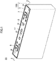
FIG. 1 is a perspective view of a secondary battery of an embodiment. -
FIG. 2 is a cross-sectional view taken along line II-II inFIG. 1 . -
FIG. 3 is a plan view of a positive electrode plate. -
FIG. 4 is a plan view of a negative electrode plate. -
FIG. 5 is a plan view of an electrode body. -
FIG. 6 is a plan view of a first positive electrode current collector (positive electrode current collector). -
FIG. 7 is a plan view of a first negative electrode current collector (negative electrode current collector). -
FIG. 8 shows that a positive electrode tab group is connected to the first positive electrode current collector, and a negative electrode tab group is connected to the first negative electrode current collector. -
FIG. 9 shows the surface of a sealing plate facing the electrode body after attaching second positive and negative electrode current collectors. -
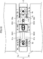
FIG. 10 shows the surface of the sealing plate facing the electrode body after attaching the first positive electrode current collector to the second positive electrode current collector, and the first negative electrode current collector to the second negative electrode current collector. -
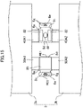
FIG. 11 corresponds toFIG. 10 with first, third, and fourth tapes attached. -
FIG. 12 corresponds toFIG. 11 with a cover member attached. -
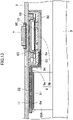
FIG. 13 is a cross-sectional view taken along line XIII-XIII inFIG. 1 . -
FIG. 14 is a cross-sectional view taken along line XIV-XIV inFIG. 1 . -
FIG. 15 corresponds toFIG. 8 with second and fifth tapes attached. - Hereinafter, an embodiment of the present invention will be described in detail with reference to the drawings. The following description of an advantageous embodiment is a mere example in nature, and is not at all intended to limit the scope, applications or use of the present invention. In the drawings below, constituent features substantially sharing the same function are denoted with the same reference sign for the sake of simplicity.
- A configuration of a rectangular
secondary battery 20 as a secondary battery of an embodiment will be described below. Note that the present invention is not limited to the following embodiment. - As shown in
FIGS. 1 and2 , the rectangularsecondary battery 20 includes abattery case 100 including a rectangularexterior body 1 and asealing plate 2. Therectangular exterior body 1 is in the shape of a bottomed rectangular tube with an opening. Thesealing plate 2 is in the shape of a substantially rectangular plate and seals the opening of the rectangularexterior body 1. Each of the rectangularexterior body 1 and thesealing plate 2 is made of metal, particularly, aluminum or an aluminum alloy in one preferred embodiment. Thesealing plate 2 has, near respective longitudinal ends, a positive electrodeterminal insertion hole 2a and a negative electrodeterminal insertion hole 2b. Thesealing plate 2 has, at a point closer to the positive electrodeterminal insertion hole 2a than the longitudinal center, anelectrolyte inlet 15 which is sealed by a sealing member (not shown) after injecting the electrolyte. Thesealing plate 2 has, at the longitudinal center, agas discharge valve 17 which is broken once the pressure inside thebattery case 100 reaches a predetermined value or more to discharge the gas inside thebattery case 100 outside thebattery case 100. - The rectangular
exterior body 1 houses anelectrode body 3 obtained by stacking a positive electrode plate 4 shown inFIG. 3 and anegative electrode plate 5 shown inFIG. 4 with a separator interposed therebetween, together with an electrolyte. The positive electrode plate 4 haspositive electrode tabs 40, whereas thenegative electrode plate 5 hasnegative electrode tabs 50. - As shown in
FIG. 5 , theelectrode body 3 includes, at the end at the sealingplate 2, positive and negativeelectrode tab groups plate 2. The positiveelectrode tab group 40A includes the positive electrode tabs (tabs) 40 projecting toward the sealingplate 2. The negativeelectrode tab group 50A includes the negative electrode tabs (tabs) 50 projecting toward the sealingplate 2. The positiveelectrode tab group 40A is electrically connected to apositive electrode terminal 7 via a first positive electrodecurrent collector 6a and a second positive electrodecurrent collector 6b. The negativeelectrode tab group 50A is electrically connected to anegative electrode terminal 9 via a first negative electrodecurrent collector 8a and a second negative electrodecurrent collector 8b. - As shown in
FIG. 8 , theelectrode body 3 includes first and secondelectrode body elements negative electrode plates 4 and 5 with a separator interposed therebetween. These twoelectrode body elements electrode body element 3a includes a first positive electrode tab group 40A1 and a first negative electrode tab group 50A1. The secondelectrode body element 3b includes a second positive electrode tab group 40A2 and a second negative electrode tab group 50A2. - As shown in
FIGS. 6 and13 , the first positive electrodecurrent collector 6a is in the shape of a plate substantially parallel to the sealingplate 2. Specifically, the first positive electrodecurrent collector 6a includes astep 6c near one end (the end farther from the negative electrode terminal 9) in the longitudinal direction of the sealingplate 2. The area closer to the other end in the longitudinal direction of the sealingplate 2 than thestep 6c serves as amain plate 6d. The area closer to the one end in the longitudinal direction of the sealingplate 2 than thestep 6c serves an electrode body-side plate 6e closer to theelectrode body 3 than themain plate 6d. Themain plate 6d has a current collector through-hole 6f to face theelectrolyte inlet 15 of the sealingplate 2. The electrode body-side plate 6e hasthin parts 6g. - The second positive electrode
current collector 6b is in the shape of a plate substantially parallel to the sealingplate 2. - The
thin parts 6g of the electrode body-side plate 6e of the first positive electrodecurrent collector 6a are integrally welded to the second positive electrodecurrent collector 6b from theelectrode body 3 side. The first and second positive electrodecurrent collectors current collector 6. - The first and second positive electrode
current collectors positive electrode terminal 7 are made of metal, particularly, aluminum or an aluminum alloy in one preferred embodiment. - Interposed between the
positive electrode terminal 7 and the sealingplate 2 is anexternal insulation member 10 of a resin. A firstinternal insulation member 18 is located inside the battery (closer to the electrode body 3) around the positive electrodeterminal insertion hole 2a of the sealingplate 2. The firstinternal insulation member 18 abuts on the sealingplate 2 from the inside of the battery. Each of theexternal insulation member 10 and the firstinternal insulation member 18 has, in the point corresponding to the positive electrodeterminal insertion hole 2a of the sealingplate 2, a through-hole for inserting thepositive electrode terminal 7. A cup-shapedconductive member 65 is located in the firstinternal insulation member 18 inside the battery (closer to the electrode body 3) with its opening oriented inside the battery. Theconductive member 65 has a terminal connection hole penetrating therethrough. In theconductive member 65 inside the battery, a disk-shapeddeformable plate 66 closes the opening of theconductive member 65. The peripheral edge of thedeformable plate 66 is welded and connected to theconductive member 65 to seal the opening of theconductive member 65. Each of theconductive member 65 and thedeformable plate 66 is made of metal, particularly, aluminum or an aluminum alloy in one preferred embodiment. - Interposed between the first and second positive electrode
current collectors plate 2 is a secondinternal insulation member 11 of a resin. The secondinternal insulation member 11 abuts on the periphery of theelectrolyte inlet 15 of the sealingplate 2 and thedeformable plate 66 from the inside of the battery. The secondinternal insulation member 11 has a liquid injection opening 11a to face theelectrolyte inlet 15 of the sealingplate 2. The secondinternal insulation member 11 has, at the edge of the liquid injection opening 11a, atube 11b projecting toward the inside of the battery. The secondinternal insulation member 11 further includes anopening cover 11c projecting from two points on the edge of thetube 11b toward the inside of the battery to connect the two points like a bridge. The secondinternal insulation member 11 further has a through-hole partially overlapping thedeformable plate 66. - As shown in
FIG. 8 , the distal ends of the first and second positive electrode tab groups 40A1 and 40A2 are welded to two areas sandwiching the current collector through-hole 6f from both sides in the transverse direction of the sealingplate 2 on the surface of themain plate 6d of the first positive electrodecurrent collector 6a facing theelectrode body 3. That is, the welding areas at the distal ends of the first and second positive electrode tab groups 40A1 and 40A2 are spaced apart from each other in the transverse direction of the sealingplate 2 with the current collector through-hole 6f interposed therebetween. InFIG. 8 ,reference character 60a denotes the distal end, that is, the welding point of the first positive electrode tab group 40A1, whereasreference character 60b denotes the distal end, that is, the welding point of the second positive electrode tab group 40A2. As shown inFIG. 11 , thewelding points welding points current collector 6a facing theelectrode body 3 from two sides in the transverse direction of the sealingplate 2 is covered with afirst tape 81 as the electrode body-side covering member from theelectrode body 3 side. The two ends of thefirst tape 81 in the transverse direction of the sealingplate 2 are applied to thewelding points first tape 81 in the transverse direction of the sealingplate 2 and each of the current collector through-hole 6f of the first positive electrodecurrent collector 6a, the liquid injection opening 11a and theopening cover 11c of the secondinternal insulation member 11, and theelectrolyte inlet 15 of the sealingplate 2. - As shown in
FIG. 15 , on the surface of themain plate 6d of the first positive electrodecurrent collector 6a facing the sealingplate 2, the areas corresponding to the back of the welded area of the first and second positive electrode tab groups 40A1 and 40A2 are covered withsecond tapes 82 as rectangular sealing plate-side covering members. The wholesecond tapes 82 are applied to the first positive electrodecurrent collector 6a. - Applied to the electrode body-
side plate 6e of the first positive electrodecurrent collector 6a from theelectrode body 3 side is athird tape 83 to cover the welding point between the first and second positive electrodecurrent collectors - As shown in
FIGS. 7 and14 , the first negative electrodecurrent collector 8a is in the shape of a plate substantially parallel to the sealingplate 2. Specifically, the first negative electrodecurrent collector 8a includes astep 8c near one end (the end farther from the positive electrode terminal 7) in the longitudinal direction of the sealingplate 2. The area closer to the other end in the longitudinal direction of the sealingplate 2 than thestep 8c serves as afirst plate 8d. The area closer to the one end in the longitudinal direction of the sealingplate 2 than thestep 8c serves asecond plate 8e closer to theelectrode body 3 than thefirst plate 8d. The surface of thefirst plate 8d facing the sealingplate 2 serves as a first area RE1, whereas the surface of thesecond plate 8e facing the sealingplate 2 serves as a second area RE2 which is closer to theelectrode body 3 than the first area RE1 is. InFIG. 14 , reference character D denotes the step between the first and second areas RE1 and RE2. Thesecond plate 8e has, on the surface facing theelectrode body 3, arecess 8f toward the sealingplate 2. Therecess 8f hasthin parts 8g. - The second negative electrode
current collector 8b is in the shape of a plate substantially parallel to the sealingplate 2. The second negative electrodecurrent collector 8b has a terminal connection hole. InFIG. 14 , reference character T1 denotes the thickness of the second negative electrodecurrent collector 8b. - The second negative electrode
current collector 8b is integrally welded to thethin parts 8g (i.e., the second area RE) of thesecond plate 8e of the first negative electrodecurrent collector 8a. The surface of the second negative electrodecurrent collector 8b facing theelectrode body 3 abuts on the second area RE2 of the first negative electrodecurrent collector 8a. The first and second negative electrodecurrent collectors current collector 8. - The first and second negative electrode
current collectors negative electrode terminal 9 are made of metal, particularly, copper or a copper alloy in one preferred embodiment. Thenegative electrode terminal 9 has a part made of aluminum or an aluminum alloy, and a part made of copper or a copper alloy in one preferred embodiment. In this case, the part made of copper or a copper alloy is connected to the second negative electrodecurrent collector 8b, and the part made of aluminum or an aluminum alloy projects outward beyond the sealingplate 2 in one preferred embodiment. - Interposed between the
negative electrode terminal 9 and the sealingplate 2 is anexternal insulation member 12 of a resin. Interposed between the first and second negative electrodecurrent collectors plate 2 is aninternal insulation member 13 of a resin. Theinternal insulation member 13 is fixed while abutting on the sealingplate 2 from the inside of the battery. Each of theexternal insulation member 12 and theinternal insulation member 13 has a through-hole in the point corresponding to the negative electrodeterminal insertion hole 2b of the sealingplate 2. - The surface of the
internal insulation member 13 facing theelectrode body 3 has a flat area FRE. Abutting on the flat area FRE is the surface of the second negative electrodecurrent collector 8b facing the sealingplate 2. - The distal ends of the first and second negative electrode tab groups 50A1 and 50A2 are welded to the surface of the
first plate 8d of the first negative electrodecurrent collector 8a facing theelectrode body 3. That is, the welding areas at the distal ends of the first and second negative electrode tab groups 50A1 and 50A2 are spaced apart from each other in the transverse direction of the sealingplate 2. InFIG. 8 ,reference character 61a denotes the distal end, that is, the welding point of the first negative electrode tab group 50A1, whereasreference character 61b denotes the distal end, that is, the welding point of the second negative electrode tab group 50A2. The distal ends, that are, thewelding points welding points first plate 8d facing theelectrode body 3 from two sides in the transverse direction of the sealingplate 2, and the welding point of thesecond plate 8e to the second negative electrodecurrent collector 8b are covered with a singlefourth tape 84 as an electrode body-side covering member from theelectrode body 3 side. Thefourth tape 84 is applied to thewelding points second plate 8e other than therecess 8f. - Applied to the surface of the
first plate 8d of the first negative electrodecurrent collector 8a facing the sealingplate 2, that is, the first area RE1 is a singlefifth tape 85 as a sealing plate-side covering member across the entire area except the peripheral end thereof. Thisfifth tape 85 covers two areas corresponding to the back of the welding areas of the first and second negative electrode tab groups 50A1 and 50A2 on the surface (i.e., the first area RE1) of thefirst plate 8d of the first negative electrodecurrent collector 8a facing the sealingplate 2. - Each of the first to
fifth tapes 81 to 85 includes a base material that is a polypropylene film, and an adhesive layer made of a rubber-based adhesive applied to one surface of the polypropylene film. The first tofifth tapes 81 to 85 have the thickness set equal to each other. InFIG. 14 , reference character T2 denotes the thickness of thefifth tape 85. The thickness T1 of the second negative electrodecurrent collector 8b is set larger than the sum of the step D between the first and second areas RE1 and RE2 of the first negative electrodecurrent collector 8a and the thickness T2 of thefifth tape 85. - Interposed between the
electrode body 3 and the rectangularexterior body 1 is anelectrode body holder 14 that is a resin sheet. A resin insulation sheet is folded and molded into a bag or a box as theelectrode body holder 14 in one preferred embodiment. Thiselectrode body holder 14 reliably keeps theelectrode body 3 and the rectangularexterior body 1 electrically insulated from each other. - Now, the details of a production method and components of the rectangular
secondary battery 20 will be described. - First, a method of producing the positive electrode plate 4 will be described.
- A slurry for a positive electrode active material mixture layer is prepared by kneading a positive electrode active material, a conductive agent, and a binder, for example. Examples of the positive electrode active material include lithium composite oxides such as lithium nickel cobalt manganese composite oxides. Examples of the binder include fluorine resins such as polyvinylidene fluoride (PVdF). Examples of the conductive agent include carbon materials such as carbon black.
- Alumina powder, graphite as a conductive agent, polyvinylidene fluoride (PVdF) as a binder, N-methyl-2-pyrrolidone (NMP) as a dispersion medium are kneaded into a slurry for a protective layer.
- The slurries for the positive electrode active material mixture layer and the positive electrode protective layer prepared as described above are applied to both sides of an aluminum foil as a positive electrode core with a thickness of 15 µm by a die coater. The slurry for the positive electrode protective layer is applied to at least one transverse end of an area applied with the slurry of the positive electrode active material mixture layer.
- The positive electrode core applied with the slurries for the positive electrode active material mixture layer and the positive electrode protective layer is dried to remove NMP inside the slurry. Accordingly, the positive electrode active material mixture layer and the protective layer are formed. After that, the positive electrode active material mixture layer passes between a pair of press rollers so as to be compressed into a positive electrode original plate. This positive electrode original plate is cut into a predetermined size as the positive electrode plate 4 shown in
FIG. 3 . The positive electrode plate 4 has a rectangular shape with an upper side from which thepositive electrode tabs 40 project. The positive electrode plate 4 includes a narrow positive electrodeprotective layer 4c along the upper side, and a positive electrode activematerial mixture layer 4b from the bottom of the positive electrodeprotective layer 4c to the lower side of the positive electrode plate 4. As described above, thepositive electrode tabs 40 may be formed from the positive electrode core, or another member may be connected to the positive electrode plate 4 to serve as thepositive electrode tabs 40. - Next, a method of producing the
negative electrode plate 5 will be described. - A slurry for a negative electrode active material mixture layer is prepared by kneading a negative electrode active material, a conductive agent, a binder, and a thickener. Examples of the negative electrode active material include carbon materials such as graphite. Examples of the binder include styrene butadiene rubber (SBR). Examples of the thickener include carboxymethyl cellulose (CMC).
- The slurry for the negative electrode active material mixture layer prepared as described above is applied to both sides of a copper foil as a negative electrode core with a thickness of 8 µm by a die coater.
- The negative electrode core applied with the slurry for the negative electrode active material mixture layer is dried to remove water inside the slurry. Accordingly, the negative electrode active material mixture layer is formed. After that, the negative electrode active material mixture layer passes between a pair of press rollers so as to be compressed into a negative electrode original plate. This negative electrode original plate is cut into a predetermined size as the
negative electrode plate 5 shown inFIG. 4 . Thenegative electrode plate 5 has a rectangular shape with an upper side from which thenegative electrode tabs 50 project. Accordingly, the negative electrode activematerial mixture layer 5b is formed on the entire surface of the negative electrode core except thenegative electrode tabs 50. As described above, thenegative electrode tabs 50 may be formed from the negative electrode core, or another member may be connected to thenegative electrode plate 5 to serve as thenegative electrode tabs 50. - The positive and
negative electrode plates 4 and 5 prepared as described above are stacked one on the other with a separator interposed therebetween to obtain themultilayer electrode body 3. The numbers of the positive andnegative electrode plates 4 and 5 included in theelectrode body 3 are not particularly limited but may be tens or more in one preferred embodiment. Specifically, the first and secondelectrode body elements electrode body 3. - As shown in
FIG. 8 , the first positive electrode tab group 40A1 of the firstelectrode body element 3a and the second positive electrode tab group 40A2 of the secondelectrode body element 3b are welded to one surface of themain plate 6d of the first positive electrodecurrent collector 6a (positive electrode current collector 6) shown inFIG. 6 . The first negative electrode tab group 50A1 of the firstelectrode body element 3a and the second negative electrode tab group 50A2 of the secondelectrode body element 3b are welded to one surface of thefirst plate 8d of the first negative electrodecurrent collector 8a (negative electrode current collector 8) shown inFIG, 7 . - The welding connection between the positive
electrode tab group 40A and the first positive electrodecurrent collector 6a and between the negativeelectrode tab group 50A and the first negative electrodecurrent collector 8a are made by ultrasonic welding, resistance welding, or laser welding, for example. In this embodiment, the welding connection is made by ultrasonic welding. - After that, as shown in
FIG. 15 , twosecond tapes 82 are applied to the other surface of themain plate 6d of the first positive electrodecurrent collector 6a, and thefifth tape 85 is applied to the other surface of thefirst plate 8d of the first negative electrodecurrent collector 8a. Accordingly, thesecond tapes 82 capture the foreign objects adhering to the surface of the first positive electrodecurrent collector 6a farther from the surface connected to the positiveelectrode tab group 40A, particularly the metal powder generated in the welding process of the positiveelectrode tab group 40A not to cause the foreign objects to enter the inside of theelectrode body 3. Similarly, thefifth tape 85 captures the foreign objects adhering to the surface of the first negative electrodecurrent collector 8a farther from the surface connected to the negativeelectrode tab group 50A, particularly the metal powder generated in the welding process of the negativeelectrode tab group 50A not to cause the foreign objects to enter the inside of theelectrode body 3. This largely reduces the internal short circuits caused by the foreign objects. -
FIG. 9 shows the surface of the sealingplate 2 facing the inside of the battery and attached with the components. The attachment of the components to the sealingplate 2 will be described with reference toFIGS. 2 and9 . - The
external insulation member 10 surrounds a positive electrodeterminal insertion hole 2a of the sealingplate 2. The firstinternal insulation member 18 and the cup-shapedconductive member 65 are arranged on the inner surface of the battery around the positive electrodeterminal insertion hole 2a of the sealingplate 2. Thepositive electrode terminal 7 is then inserted from the outside of the battery through the through-hole of theexternal insulation member 10, the positive electrodeterminal insertion hole 2a of the sealingplate 2, the through-hole of the firstinternal insulation member 18, and a terminal connection hole of theconductive member 65. The tip of thepositive electrode terminal 7 is crimped onto theconductive member 65. As a result, thepositive electrode terminal 7 and theconductive member 65 are fixed to the sealingplate 2. The crimped part of thepositive electrode terminal 7 and theconductive member 65 are welded and connected in one preferred embodiment. - The disk-shaped
deformable plate 66 closes the opening of theconductive member 65, and has a peripheral edge welded and connected to theconductive member 65. Accordingly, the opening of theconductive member 65 is sealed. Next, the secondinternal insulation member 11 of a resin is located on the periphery of theelectrolyte inlet 15 of the sealingplate 2 and the side of thedeformable plate 66 closer to theelectrode body 3. Then, the second positive electrodecurrent collector 6b is placed inside the battery with respect to the secondinternal insulation member 11, and thedeformable plate 66 and the second positive electrodecurrent collector 6b are welded and connected through the through-hole of the secondinternal insulation member 11. - On the other hand, the
external insulation member 12 is placed on the outer surface of the battery around the negative electrodeterminal insertion hole 2b of the sealingplate 2. Theinternal insulation member 13 and the second negative electrodecurrent collector 8b are arranged on the inner surface of the battery around the negative electrodeterminal insertion hole 2b of the sealingplate 2. Thenegative electrode terminal 9 is then inserted from the outside of the battery through the through-hole of theexternal insulation member 12, the negative electrodeterminal insertion hole 2b of the sealingplate 2, the through-hole of theinternal insulation member 13, and the terminal connection hole of the second negative electrodecurrent collector 8b. The tip of thenegative electrode terminal 9 is crimped onto the second negative electrodecurrent collector 8b. As a result, thenegative electrode terminal 9 and the second negative electrodecurrent collector 8b are fixed to the sealingplate 2. The crimped part of thenegative electrode terminal 9 and the second negative electrodecurrent collector 8b are welded and connected in one preferred embodiment. -
FIG. 10 shows the surface of the sealingplate 2 facing the inside of the electrode body after attaching the first positive electrodecurrent collector 6a to the second positive electrodecurrent collector 6b, and the first negative electrodecurrent collector 8a to the second negative electrodecurrent collector 8b. - The first positive electrode
current collector 6a connected to the first and second positive electrode tab groups 40A1 and 40A2 is placed on the secondinternal insulation member 11 so that a part thereof (the electrode body-side plate 6e) overlaps the second positive electrodecurrent collector 6b. By irradiating thethin parts 6g with laser, the first and second positive electrodecurrent collectors current collector 8a connected to the first and second negative electrode tab groups 50A1 and 50A2 is placed on theinternal insulation member 13 so that a part thereof (thesecond plate 8e) overlaps the second negative electrodecurrent collector 8b. By irradiating thethin parts 8g with laser, the first and second negative electrodecurrent collectors FIG. 14 , the thickness T1 of the second negative electrodecurrent collector 8b is set larger than the sum of the step D between the first and second areas RE1 and RE2 of the first negative electrodecurrent collector 8a and the thickness T2 of thefifth tape 85. This causes less floating of thesecond plate 8e of the first negative electrodecurrent collector 8a from the second negative electrodecurrent collector 8b. This allows more reliable welding between the first and second negative electrodecurrent collectors - While, in this embodiment, the first and second positive electrode
current collectors - After that, as shown in
FIG. 11 , thefirst tape 81 is applied to thewelding points welding points welding points current collector 6a facing theelectrode body 3 from two sides in the transverse direction of the sealingplate 2. Accordingly, thefirst tape 81 catches the foreign objects existing around thewelding points electrode tab group 40A not to cause the foreign objects to enter the inside of theelectrode body 3. This largely reduces the internal short circuits caused by the foreign objects. - The
third tape 83 is applied to the surface of the electrode body-side plate 6e of the first positive electrodecurrent collector 6a facing theelectrode body 3 to cover the welding point between the first and second positive electrodecurrent collectors third tape 83 catches the foreign objects existing around the welding point between the first and second positive electrodecurrent collectors current collectors electrode body 3. This largely reduces the internal short circuits caused by the foreign objects. - In addition, in order to cover the
welding points welding points current collector 8a facing theelectrode body 3 from two sides in the transverse direction of the sealingplate 2, and the welding point between the first and second negative electrodecurrent collectors fourth tape 84 is applied to thewelding points second plate 8e other than therecess 8f from theelectrode body 3 side. Accordingly, thefourth tape 84 catches the foreign objects existing around thewelding points electrode tab group 50A not to cause the foreign objects to enter the inside of theelectrode body 3. This largely reduces the internal short circuits caused by the foreign objects. - The
fourth tape 84 covers the welding point between the first and second negative electrodecurrent collectors fourth tape 84 catches the foreign objects existing around the welding joint between the first and second negative electrodecurrent collectors current collectors electrode body 3. This largely reduces the internal short circuits caused by the foreign objects. - As shown in
FIG. 12 , the entire second positive electrodecurrent collector 6b, the electrode body-side plate 6e of the first positive electrodecurrent collector 6a, and thethird tape 83 are then covered with acover member 88. - In this embodiment, each of the first to
fifth tapes 81 to 85 is a polypropylene film, but may be a plastic film other than the polypropylene film. - In place of the first to
fifth tapes 81 to 85, each covering member may be made of a coating material such as a sealing resin that is cured by heat or light, or an adhesive sheet made of a metal foil, and a non-woven fabric, or other materials. - Each of the first to
fifth tapes 81 to 85 may be replaced with a sheet or a cushion material without any adhesive layer. - Next, the two positive electrode tab groups 40A1 and 40A2 and the two negative electrode tab groups 50A1 and 50A2 are curved so that the upper surfaces of the first and second
electrode body elements FIG. 12 are in direct contact or indirect contact with each other with other members interposed therebetween. Accordingly, the twoelectrode body elements electrode body 3. Theintegrated electrode body 3 is placed in theelectrode body holder 14 obtained by molding an insulating sheet into a box or a bag. - The
electrode body 3 wrapped with theelectrode body holder 14 is inserted into the rectangularexterior body 1. The sealingplate 2 and the rectangularexterior body 1 are welded to seal the opening of the rectangularexterior body 1 with the sealingplate 2. The electrolyte is then injected into the rectangularexterior body 1 through theelectrolyte inlet 15 of the sealingplate 2. After that, theelectrolyte inlet 15 is sealed with a sealing member such as a blind rivet. As a result, the rectangularsecondary battery 20 is complete. - The above embodiment is a mere example of the present invention. The present invention is not limited to the example. Instead, the present invention may be a combination of a well-known art, a conventional technique, and a publicly-known technique with the example, and may also have a part of the example replaced. Moreover, the present invention includes modifications at which those skilled in the art easily arrive.
- The
electrode body 3 may be wound after stacking the positive electrode plate 4, thenegative electrode plate 5, and the separator. Each of theelectrode body elements - An example has been described above in the embodiment where the two
electrode body elements exterior body 1, but the number of the electrode body elements may be one, three, or more. - An example has been described above in the embodiment where each of the positive and negative electrode
current collectors current collectors - In the embodiment described above, both the positive and
negative electrode plates 4 and 5 have the tabs, but one of the positive andnegative electrode plates 4 and 5 may have the tabs. - The positive electrode plate 4, the
negative electrode plate 5, the separator, the electrolyte, and other components may be made of known materials. -
- 1
- Exterior Body
- 2
- Sealing Plate
- 3
- Electrode Body
- 4
- Positive Electrode Plate
- 5
- Negative Electrode Plate
- 6
- Positive Electrode Current Collector
- 7
- Positive Electrode Terminal
- 8
- Negative Electrode Current Collector
- 8a
- First Negative Electrode Current Collector
- 8b
- Second Negative Electrode Current Collector
- 9
- Negative Electrode Terminal
- 13
- Internal Insulation Member
- 40
- Positive Electrode Tab (Tab)
- 50
- Negative Electrode Tab (Tab)
- 81
- First Tape (Electrode Body-Side Covering Member)
- 82
- Second Tape (Sealing Plate-Side Covering Member)
- 84
- Fourth Tape (Electrode Body-Side Covering Member)
- 85
- Fifth Tape (Sealing Plate-Side Covering Member)
- FRE
- Flat Area
- RE1
- First Area
- RE2
- Second Area
Claims (3)
- A battery comprising:an electrode body obtained by stacking a positive electrode plate and a negative electrode plate with a separator interposed therebetween, at least one of the positive electrode plate or the negative electrode plate including a tab;an exterior body having an opening and housing the electrode body;a sealing plate sealing the opening;an external terminal attached to the sealing plate; anda substantially plate-shaped current collector arranged substantially parallel to the sealing plate between the electrode body and the sealing plate and electrically connected to the external terminal,the tab of the electrode body being welded to a surface of the current collector facing the electrode body,a sealing plate-side covering member covering an area corresponding to a back of a welding area of the tab on a surface of the current collector facing the sealing plate.
- The battery of claim 1, whereinfixed to the sealing plate is an internal insulation member having a flat area on a surface facing the electrode body,the current collector includes a first current collector substantially in a shape of a plate and a second current collector substantially in a shape of a plate, the first current collector including a first area and a second area closer to the electrode body than the first area on the surface facing the sealing plate, the second current collector being welded to the second area of the first collector, the second current collector having a thickness set larger than a sum of a step between the first area and the second area of the first current collector and a thickness of the sealing plate-side covering member,the first area of the first current collector is covered with the sealing plate-side covering member, anda surface of the second current collector facing the sealing plate abuts on the flat area of the internal insulation member, whereas a surface of the second current collector facing the electrode body abuts on the second area of the first current collector.
- The battery of claim 1 or 2, wherein
an electrode body-side covering member covers a welding point between the tab and the current collector.
Applications Claiming Priority (2)
| Application Number | Priority Date | Filing Date | Title |
|---|---|---|---|
| JP2019145421 | 2019-08-07 | ||
| PCT/JP2020/024536 WO2021024630A1 (en) | 2019-08-07 | 2020-06-23 | Battery |
Publications (2)
| Publication Number | Publication Date |
|---|---|
| EP4012831A1 true EP4012831A1 (en) | 2022-06-15 |
| EP4012831A4 EP4012831A4 (en) | 2022-09-28 |
Family
ID=74502921
Family Applications (1)
| Application Number | Title | Priority Date | Filing Date |
|---|---|---|---|
| EP20850393.8A Pending EP4012831A4 (en) | 2019-08-07 | 2020-06-23 | Battery |
Country Status (5)
| Country | Link |
|---|---|
| US (1) | US20220302534A1 (en) |
| EP (1) | EP4012831A4 (en) |
| JP (1) | JP7471304B2 (en) |
| CN (1) | CN114175317A (en) |
| WO (1) | WO2021024630A1 (en) |
Cited By (1)
| Publication number | Priority date | Publication date | Assignee | Title |
|---|---|---|---|---|
| EP4250465A3 (en) * | 2022-03-26 | 2023-11-22 | Zhuhai CosMX Battery Co., Ltd. | Battery |
Family Cites Families (9)
| Publication number | Priority date | Publication date | Assignee | Title |
|---|---|---|---|---|
| JP2009087812A (en) | 2007-10-01 | 2009-04-23 | Toyota Motor Corp | Sealed battery |
| CN104475962A (en) * | 2014-11-26 | 2015-04-01 | 山东神工海特电子科技有限公司 | Lithium battery tab ultrasonic bonder with dust removal function and welding method |
| WO2018021372A1 (en) * | 2016-07-29 | 2018-02-01 | 三洋電機株式会社 | Secondary battery |
| JP6972703B2 (en) * | 2017-06-26 | 2021-11-24 | 三洋電機株式会社 | Square secondary battery |
| JP7035348B6 (en) * | 2017-06-29 | 2022-04-01 | 三洋電機株式会社 | Square secondary battery and its manufacturing method |
| JP7167427B2 (en) * | 2017-11-09 | 2022-11-09 | 三洋電機株式会社 | secondary battery |
| JP6962168B2 (en) | 2017-12-12 | 2021-11-05 | 三洋電機株式会社 | Square secondary battery and its manufacturing method |
| JP2019145272A (en) | 2018-02-19 | 2019-08-29 | 株式会社豊田自動織機 | Power storage device and manufacturing method of power storage device |
| CN109326746A (en) * | 2018-10-25 | 2019-02-12 | 江苏塔菲尔新能源科技股份有限公司 | A kind of battery cap gluing structure and its sticking method |
-
2020
- 2020-06-23 CN CN202080054554.3A patent/CN114175317A/en active Pending
- 2020-06-23 WO PCT/JP2020/024536 patent/WO2021024630A1/en unknown
- 2020-06-23 JP JP2021537613A patent/JP7471304B2/en active Active
- 2020-06-23 US US17/633,148 patent/US20220302534A1/en active Pending
- 2020-06-23 EP EP20850393.8A patent/EP4012831A4/en active Pending
Cited By (1)
| Publication number | Priority date | Publication date | Assignee | Title |
|---|---|---|---|---|
| EP4250465A3 (en) * | 2022-03-26 | 2023-11-22 | Zhuhai CosMX Battery Co., Ltd. | Battery |
Also Published As
| Publication number | Publication date |
|---|---|
| CN114175317A (en) | 2022-03-11 |
| WO2021024630A1 (en) | 2021-02-11 |
| EP4012831A4 (en) | 2022-09-28 |
| JP7471304B2 (en) | 2024-04-19 |
| JPWO2021024630A1 (en) | 2021-02-11 |
| US20220302534A1 (en) | 2022-09-22 |
Similar Documents
| Publication | Publication Date | Title |
|---|---|---|
| US9583783B2 (en) | Prismatic secondary battery | |
| US8216715B2 (en) | Prismatic battery | |
| US20120202105A1 (en) | Stack type battery and method of manufacturing the same | |
| US20110195287A1 (en) | Prismatic sealed secondary cell and method of manufacturing the same | |
| US20190006717A1 (en) | Rectangular secondary battery and method of manufacturing the same | |
| US11923558B2 (en) | Rectangular secondary battery | |
| US10916760B2 (en) | Secondary battery and method of manufacturing same | |
| US9620762B2 (en) | Electrical storage element | |
| TW201703310A (en) | Housing of electricity storage device and electricity storage device including a metal layer that is formed by a metal foil and a thermoplastic resin layer laminated on one side of the metal layer | |
| WO2020110976A1 (en) | Battery and manufacturing method thereof | |
| US20190115611A1 (en) | Method of manufacturing secondary battery | |
| US20220352606A1 (en) | Secondary battery and method for manufacturing same | |
| US20220069359A1 (en) | Rectangular secondary battery | |
| US10158107B2 (en) | Battery comprising insulative films | |
| EP4012831A1 (en) | Battery | |
| EP4012832A1 (en) | Battery | |
| JP2020030899A (en) | Secondary battery | |
| EP4012796A1 (en) | Battery | |
| WO2020129999A1 (en) | Electrode plate for secondary cell, and secondary cell using same | |
| JP2020173989A (en) | Non-aqueous electrolyte secondary battery | |
| JP2000077055A (en) | Lithium secondary battery | |
| KR20190112582A (en) | Battery cell cartridge having uniformity surface pressure | |
| CN108695543B (en) | Secondary battery and method for manufacturing same | |
| EP3902031A1 (en) | Electrode plate for secondary batteries, and secondary battery using same | |
| JP2015128026A (en) | Square secondary battery |
Legal Events
| Date | Code | Title | Description |
|---|---|---|---|
| STAA | Information on the status of an ep patent application or granted ep patent |
Free format text: STATUS: THE INTERNATIONAL PUBLICATION HAS BEEN MADE |
|
| PUAI | Public reference made under article 153(3) epc to a published international application that has entered the european phase |
Free format text: ORIGINAL CODE: 0009012 |
|
| STAA | Information on the status of an ep patent application or granted ep patent |
Free format text: STATUS: REQUEST FOR EXAMINATION WAS MADE |
|
| 17P | Request for examination filed |
Effective date: 20220207 |
|
| AK | Designated contracting states |
Kind code of ref document: A1 Designated state(s): AL AT BE BG CH CY CZ DE DK EE ES FI FR GB GR HR HU IE IS IT LI LT LU LV MC MK MT NL NO PL PT RO RS SE SI SK SM TR |
|
| A4 | Supplementary search report drawn up and despatched |
Effective date: 20220831 |
|
| RIC1 | Information provided on ipc code assigned before grant |
Ipc: H01M 50/536 20210101ALI20220825BHEP Ipc: H01M 50/176 20210101ALI20220825BHEP Ipc: H01M 50/15 20210101ALI20220825BHEP Ipc: H01M 50/103 20210101ALI20220825BHEP Ipc: H01M 50/572 20210101ALI20220825BHEP Ipc: H01M 50/531 20210101AFI20220825BHEP |
|
| DAV | Request for validation of the european patent (deleted) | ||
| DAX | Request for extension of the european patent (deleted) |