EP4012829A1 - Batteriepack - Google Patents
Batteriepack Download PDFInfo
- Publication number
- EP4012829A1 EP4012829A1 EP21210838.5A EP21210838A EP4012829A1 EP 4012829 A1 EP4012829 A1 EP 4012829A1 EP 21210838 A EP21210838 A EP 21210838A EP 4012829 A1 EP4012829 A1 EP 4012829A1
- Authority
- EP
- European Patent Office
- Prior art keywords
- battery
- battery pack
- internal cavity
- housing
- fluid
- Prior art date
- Legal status (The legal status is an assumption and is not a legal conclusion. Google has not performed a legal analysis and makes no representation as to the accuracy of the status listed.)
- Pending
Links
Images




Classifications
-
- H—ELECTRICITY
- H01—ELECTRIC ELEMENTS
- H01M—PROCESSES OR MEANS, e.g. BATTERIES, FOR THE DIRECT CONVERSION OF CHEMICAL ENERGY INTO ELECTRICAL ENERGY
- H01M50/00—Constructional details or processes of manufacture of the non-active parts of electrochemical cells other than fuel cells, e.g. hybrid cells
- H01M50/20—Mountings; Secondary casings or frames; Racks, modules or packs; Suspension devices; Shock absorbers; Transport or carrying devices; Holders
- H01M50/204—Racks, modules or packs for multiple batteries or multiple cells
- H01M50/207—Racks, modules or packs for multiple batteries or multiple cells characterised by their shape
- H01M50/213—Racks, modules or packs for multiple batteries or multiple cells characterised by their shape adapted for cells having curved cross-section, e.g. round or elliptic
-
- H—ELECTRICITY
- H01—ELECTRIC ELEMENTS
- H01M—PROCESSES OR MEANS, e.g. BATTERIES, FOR THE DIRECT CONVERSION OF CHEMICAL ENERGY INTO ELECTRICAL ENERGY
- H01M50/00—Constructional details or processes of manufacture of the non-active parts of electrochemical cells other than fuel cells, e.g. hybrid cells
- H01M50/20—Mountings; Secondary casings or frames; Racks, modules or packs; Suspension devices; Shock absorbers; Transport or carrying devices; Holders
- H01M50/284—Mountings; Secondary casings or frames; Racks, modules or packs; Suspension devices; Shock absorbers; Transport or carrying devices; Holders with incorporated circuit boards, e.g. printed circuit boards [PCB]
-
- H—ELECTRICITY
- H01—ELECTRIC ELEMENTS
- H01M—PROCESSES OR MEANS, e.g. BATTERIES, FOR THE DIRECT CONVERSION OF CHEMICAL ENERGY INTO ELECTRICAL ENERGY
- H01M10/00—Secondary cells; Manufacture thereof
- H01M10/42—Methods or arrangements for servicing or maintenance of secondary cells or secondary half-cells
- H01M10/425—Structural combination with electronic components, e.g. electronic circuits integrated to the outside of the casing
-
- H—ELECTRICITY
- H01—ELECTRIC ELEMENTS
- H01M—PROCESSES OR MEANS, e.g. BATTERIES, FOR THE DIRECT CONVERSION OF CHEMICAL ENERGY INTO ELECTRICAL ENERGY
- H01M10/00—Secondary cells; Manufacture thereof
- H01M10/60—Heating or cooling; Temperature control
- H01M10/65—Means for temperature control structurally associated with the cells
- H01M10/653—Means for temperature control structurally associated with the cells characterised by electrically insulating or thermally conductive materials
-
- H—ELECTRICITY
- H01—ELECTRIC ELEMENTS
- H01M—PROCESSES OR MEANS, e.g. BATTERIES, FOR THE DIRECT CONVERSION OF CHEMICAL ENERGY INTO ELECTRICAL ENERGY
- H01M50/00—Constructional details or processes of manufacture of the non-active parts of electrochemical cells other than fuel cells, e.g. hybrid cells
- H01M50/20—Mountings; Secondary casings or frames; Racks, modules or packs; Suspension devices; Shock absorbers; Transport or carrying devices; Holders
- H01M50/204—Racks, modules or packs for multiple batteries or multiple cells
-
- H—ELECTRICITY
- H01—ELECTRIC ELEMENTS
- H01M—PROCESSES OR MEANS, e.g. BATTERIES, FOR THE DIRECT CONVERSION OF CHEMICAL ENERGY INTO ELECTRICAL ENERGY
- H01M50/00—Constructional details or processes of manufacture of the non-active parts of electrochemical cells other than fuel cells, e.g. hybrid cells
- H01M50/20—Mountings; Secondary casings or frames; Racks, modules or packs; Suspension devices; Shock absorbers; Transport or carrying devices; Holders
- H01M50/233—Mountings; Secondary casings or frames; Racks, modules or packs; Suspension devices; Shock absorbers; Transport or carrying devices; Holders characterised by physical properties of casings or racks, e.g. dimensions
- H01M50/24—Mountings; Secondary casings or frames; Racks, modules or packs; Suspension devices; Shock absorbers; Transport or carrying devices; Holders characterised by physical properties of casings or racks, e.g. dimensions adapted for protecting batteries from their environment, e.g. from corrosion
-
- H—ELECTRICITY
- H01—ELECTRIC ELEMENTS
- H01M—PROCESSES OR MEANS, e.g. BATTERIES, FOR THE DIRECT CONVERSION OF CHEMICAL ENERGY INTO ELECTRICAL ENERGY
- H01M50/00—Constructional details or processes of manufacture of the non-active parts of electrochemical cells other than fuel cells, e.g. hybrid cells
- H01M50/20—Mountings; Secondary casings or frames; Racks, modules or packs; Suspension devices; Shock absorbers; Transport or carrying devices; Holders
- H01M50/244—Secondary casings; Racks; Suspension devices; Carrying devices; Holders characterised by their mounting method
-
- H—ELECTRICITY
- H01—ELECTRIC ELEMENTS
- H01M—PROCESSES OR MEANS, e.g. BATTERIES, FOR THE DIRECT CONVERSION OF CHEMICAL ENERGY INTO ELECTRICAL ENERGY
- H01M50/00—Constructional details or processes of manufacture of the non-active parts of electrochemical cells other than fuel cells, e.g. hybrid cells
- H01M50/20—Mountings; Secondary casings or frames; Racks, modules or packs; Suspension devices; Shock absorbers; Transport or carrying devices; Holders
- H01M50/247—Mountings; Secondary casings or frames; Racks, modules or packs; Suspension devices; Shock absorbers; Transport or carrying devices; Holders specially adapted for portable devices, e.g. mobile phones, computers, hand tools or pacemakers
-
- H—ELECTRICITY
- H01—ELECTRIC ELEMENTS
- H01M—PROCESSES OR MEANS, e.g. BATTERIES, FOR THE DIRECT CONVERSION OF CHEMICAL ENERGY INTO ELECTRICAL ENERGY
- H01M50/00—Constructional details or processes of manufacture of the non-active parts of electrochemical cells other than fuel cells, e.g. hybrid cells
- H01M50/60—Arrangements or processes for filling or topping-up with liquids; Arrangements or processes for draining liquids from casings
- H01M50/609—Arrangements or processes for filling with liquid, e.g. electrolytes
- H01M50/627—Filling ports
-
- H—ELECTRICITY
- H01—ELECTRIC ELEMENTS
- H01M—PROCESSES OR MEANS, e.g. BATTERIES, FOR THE DIRECT CONVERSION OF CHEMICAL ENERGY INTO ELECTRICAL ENERGY
- H01M2220/00—Batteries for particular applications
- H01M2220/30—Batteries in portable systems, e.g. mobile phone, laptop
-
- Y—GENERAL TAGGING OF NEW TECHNOLOGICAL DEVELOPMENTS; GENERAL TAGGING OF CROSS-SECTIONAL TECHNOLOGIES SPANNING OVER SEVERAL SECTIONS OF THE IPC; TECHNICAL SUBJECTS COVERED BY FORMER USPC CROSS-REFERENCE ART COLLECTIONS [XRACs] AND DIGESTS
- Y02—TECHNOLOGIES OR APPLICATIONS FOR MITIGATION OR ADAPTATION AGAINST CLIMATE CHANGE
- Y02E—REDUCTION OF GREENHOUSE GAS [GHG] EMISSIONS, RELATED TO ENERGY GENERATION, TRANSMISSION OR DISTRIBUTION
- Y02E60/00—Enabling technologies; Technologies with a potential or indirect contribution to GHG emissions mitigation
- Y02E60/10—Energy storage using batteries
Definitions
- the present invention relates to battery packs and, more particularly, to a battery pack configured to receive adhesive material.
- electrical equipment such as a power tool
- a rechargeable battery pack typically can be powered by a rechargeable battery pack.
- the battery pack may be charged in a compatible battery charger.
- a battery pack assembly in a first aspect, there is provided a battery pack assembly.
- the battery pack assembly includes a housing having a plurality of sides and defining an internal cavity, a plurality of battery cells received in the internal cavity, and battery electronics received in the internal cavity.
- a battery pack interface is supported by the housing and connectable to a device.
- An injection port is supported by the housing.
- the injection port includes one or more channels positioned on one or more of the sides of the housing. Each channel connects the internal cavity to an exterior of the battery pack.
- the injection port is configured to direct a fluid comprising adhesive material from the exterior of the battery pack into the internal cavity.
- the fluid is configured to cover at least one of a portion of the battery cells and a portion of the battery electronics.
- the housing includes a top housing portion and a bottom housing portion, and the top housing portion includes the injection port.
- the bottom housing portion includes a battery cell holder configured to retain the plurality of battery cells within the internal cavity
- the battery cell holder includes a surface in facing relationship with the top housing portion, the surface configured to support the battery electronics, and the fluid is configured to cover a portion of the surface.
- the battery electronics includes a printed circuit board and battery contacts extending therefrom
- the battery pack interface includes a terminal block enclosing the battery contacts
- the fluid is configured to cover a surface of the printed circuit board.
- the housing includes a longitudinal axis extending therethrough, each of the one or more channels of the injection port extends along an injection axis, and the injection axis extends at an angle relative to the longitudinal axis.
- the battery electronics includes a printed circuit board, and an end of the one or more channels of the injection port is positioned proximate a surface of the printed circuit board.
- the fluid includes thermally conductive silicone encapsulant.
- a method of manufacturing a battery pack assembly includes assembling at least a portion of a housing of a battery pack assembly, positioning a plurality of battery cells and battery electronics within an internal cavity of the housing, and injecting a fluid comprising adhesive material into the internal cavity by an injection port of the housing such that the fluid covers at least one of a portion of the battery cells and a portion of the battery electronics.
- assembling at least the portion of the housing includes providing a battery cell holder, and positioning the plurality of battery cells and the battery electronics within the internal cavity includes receiving, by the battery cell holder, the plurality of battery cells, and securing a printed circuit board of the battery electronics to the battery cell holder.
- injecting the fluid includes covering a surface of the printed circuit board.
- assembling at least the portion of the housing includes coupling a bottom housing portion to a top housing portion to form the internal cavity, and injecting the fluid includes injecting the fluid through the top housing portion using the injection port.
- assembling at least the portion of the housing includes assembling a bottom housing portion, and the method further comprising injecting the fluid into the bottom housing portion before coupling a top housing portion to the bottom housing portion.
- the fluid includes thermally conductive silicone encapsulant.
- a battery pack assembly in a third aspect, there is provided a battery pack assembly.
- the battery pack assembly includes a housing having a plurality of sides and defining an internal cavity, a plurality of battery cells received in the internal cavity, and battery electronics received in the internal cavity.
- a battery pack interface is supported by the housing and connectable to a device.
- a layer comprising adhesive material is positioned within the internal cavity between a portion of the battery cells and a portion of the battery electronics, and a plurality of inner surfaces of the housing.
- the layer has a continuous surface covering the portion of the battery cells and the portion of the battery electronics.
- the layer is injectable as a fluid into the internal cavity that is configured to harden to form the layer.
- the battery pack assembly further comprises an injection port configured to direct the fluid from exterior of the battery pack into the internal cavity.
- the housing includes a top housing portion and a bottom housing portion, and the top housing portion includes the injection port.
- the bottom housing portion includes a battery cell holder configured to retain the plurality of battery cells within the internal cavity
- the battery cell holder includes a surface in facing relationship with the top housing portion, the surface configured to support the battery electronics, and the layer is configured to cover a portion of the surface.
- the battery electronics includes a printed circuit board and battery contacts extending therefrom
- the battery pack interface includes a terminal block enclosing the battery contacts
- the layer is configured to cover a surface of the printed circuit board.
- the battery electronics includes a printed circuit board, the fluid is received in the internal cavity by an injection port, and an end of the injection port is positioned proximate a surface of the printed circuit board.
- the layer includes thermally conductive silicone encapsulant.
- functionality described herein as being performed by one component may be performed by multiple components in a distributed manner. Likewise, functionality performed by multiple components may be consolidated and performed by a single component. Similarly, a component described as performing particular functionality may also perform additional functionality not described herein. For example, a device or structure that is "configured" in a certain way is configured in at least that way but may also be configured in ways that are not listed.
- non-transitory computer-readable medium comprises all computer-readable media but does not consist of a transitory, propagating signal. Accordingly, non-transitory computer-readable medium may include, for example, a hard disk, a CD-ROM, an optical storage device, a magnetic storage device, a ROM (Read Only Memory), a RAM (Random Access Memory), register memory, a processor cache, or any combination thereof.
- modules and logical structures described are capable of being implemented in software executed by a microprocessor or a similar device or of being implemented in hardware using a variety of components including, for example, application specific integrated circuits ("ASICs").
- ASICs application specific integrated circuits
- Terms like “controller” and “module” may include or refer to both hardware and/or software.
- Capitalized terms conform to common practices and help correlate the description with the coding examples, equations, and/or drawings. However, no specific meaning is implied or should be inferred simply due to the use of capitalization. Thus, the claims should not be limited to the specific examples or terminology or to any specific hardware or software implementation or combination of software or hardware.
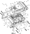
- FIGS. 1-4 illustrate a battery pack assembly 10 including a battery pack 14 and an injection port 18.
- the battery pack assembly 10 includes a high power battery pack 14 (e.g., having a nominal voltage of at least about 80 volts (V)) connectable to and operable to power various motorized power tools (e.g., a cut-off saw, a miter saw, a table saw, a core drill, an auger, a breaker, a demolition hammer, a compactor, a vibrator, a compressor, a drain cleaner, a welder, a cable tugger, a pump, etc.), outdoor tools (e.g., a chain saw, a string trimmer, a hedge trimmer, a blower, a lawn mower, etc.), other motorized devices (e.g., vehicles, utility carts, a material handling cart, etc.), etc. and non-motorized electrical devices (e.g., a power source, a light, an AC/DC adapter,
- the battery pack 14 includes a battery pack housing 30.
- the illustrated housing includes a body portion 34, a cover portion 38, and first and second side portions 42, 46 coupled to first and second sides, respectively, of the body portion 34.
- the cover portion 38 of the housing 30 may be referred to herein as a "top housing portion 50," and the body portion 34 and the first and second side 42, 46 portions may be collectively referred to herein as a "bottom housing portion 54.”
- the housing 30 may comprise one or more portions to form the housing 30.
- the housing 30 includes a longitudinal axis 58 extending therethrough.
- the housing 30 includes a front side 62, a rear side 66, a first lateral side 70, a second lateral side 74 opposite the first lateral side 70, a top side 78, and a bottom side 82 opposite the top side 78.
- the body portion 34 forms the front side 62, the rear side 66, and the bottom side 82.
- the first and second side portions 42, 46 form the first and second lateral sides 70, 74, respectively, and the cover portion 38 forms the top side 78 of the housing 30.
- the housing 30 defines an internal cavity 86 in which one or more battery cells 90 are supported. More specifically, the body portion 34 is positioned within the internal cavity 86 and is configured to receive the battery cells 90. As such, the body portion 34 is configured as a battery cell holder that restrains the battery cells 90 within the internal cavity 86.
- Each battery cell 90 may have a nominal voltage between about 3 V and about 5 V and may have a nominal capacity between about 2 Ah and about 6 Ah (in some cases, between about 3 Ah and about 5 Ah).
- the battery cells 90 may be any rechargeable battery cell chemistry type, such as, for example, lithium (Li), lithium-ion (Li-ion), other lithium-based chemistry, nickelcadmium (NiCd), nickel-metal hydride (NiMH), etc.
- the battery cells 90 may be connected in series, parallel, or combination series-parallel to provide the desired electrical characteristics (e.g., nominal voltage, current output, current capacity, power capacity, etc.) of the battery pack 14.
- the battery cells 90 are connected together by battery straps 94 ( FIG. 9B ).
- the battery cells 90 are electrically coupled to battery contacts 98 ( FIG. 4 ) supported within the housing 30 and configured to electrically and mechanically engage device contacts of the device to facilitate the transfer of electrical power between the device and the battery pack 14.
- the top housing portion 50 includes a wall 102 and a battery pack interface 106 that extends from the wall 102.
- the battery pack interface 106 includes a terminal block 110 with openings 114 extending therethrough that allow access to the battery contacts 98 ( FIG. 4 ) positioned within the housing 30.
- the terminal block 110 encloses the battery contacts 98.
- the battery pack interface 106 further includes rails 118, 122 and grooves 126, 130 positioned on opposite sides of the terminal block 110. In particular, the grooves 126, 130 are defined between the respective rail 118, 122 and the wall 102.
- the battery pack interface 106 is configured to selectively couple with a device interface having structure corresponding to the structure of the battery pack interface 106 (e.g., the device contacts and grooves/rails).
- the battery pack 14 includes battery pack electronics 134 positioned within the housing 30.
- the battery pack electronics 134 include, among other things, a printed circuit board (PCB) 138, one or more electrical component(s) 142 (e.g., CPU, a transformer, FETs, etc.)), and the battery contacts 98.
- the PCB 138 is securably coupled to (e.g., by welding) and supported by the body portion 34.
- the top housing portion 50 includes an inner surface 146 opposite the wall 102 of the top housing portion 50.
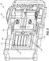
- the PCB 138 includes a surface 150 in facing relationship with and spaced from the inner surface 146 ( FIG. 6 ) of the top housing portion 50.
- the battery contacts 98 are securably coupled to (e.g., by welding) and extend from the PCB 138 toward the inner surface 146 at one end of the PCB 138. An end of the battery contacts 98 are positioned adjacent the openings 114 of the terminal block 110. In addition, the battery contacts 98 are in electrical connection with the PCB 138.
- the housing 30 includes the injection port 18.
- the injection port 18 includes one or more channels 158 positioned on one or more of the sides (e.g., top side 78, bottom side 82, front side 62, rear side 66, first lateral side 70, second lateral side 74) of the housing 30.
- the injection port 18 includes a single channel 158 defined by the top housing portion 50 such that the channel 158 is positioned on the top side 78 of the housing 30.
- the channel 158 extends between a first end 162 located on the wall 102 though the top housing portion 50 (e.g., cover portion 38) to a second, opposite end 166 located on the inner surface 146 of the top housing portion 50.
- the housing 30 may include multiple channels extending through the same or different sides of the housing 30 (e.g., two channels on the top side 78, or one channel on the top side 78 and another channel on the rear side 66, etc.).
- the injection port 18 connects the internal cavity 86 of the battery pack 14 to an exterior of the housing 30.
- the channel 158 extends along an injection axis 170.
- the injection axis 170 extends relative to the longitudinal axis 58.
- the injection axis 170 extends at an angle A (e.g., ninety degrees) relative to the longitudinal axis 58.
- the one or more channels 158 may be positioned such that the respective injection axis 170 extends parallel with the longitudinal axis 58.
- the illustrated injection axis 170 extends through the longitudinal axis 58 ( FIG. 7 ), but may alternatively be spaced away from the longitudinal axis 58.
- each injection axis 170 of the channels 158 may extend at the same or different angle A relative to the longitudinal axis 58, and/or the injection axis 170 of one, some, or all of the channels 158 may extend through or spaced away from the longitudinal axis 58.
- the channel(s) 158 may be positioned closer to some of the sides 62, 66, 70, 74, 78, 82 of the housing 30 rather than the respective opposite sides 62, 66, 70, 74, 78, 82.
- the illustrated channel 158 is positioned closer to the front side 62 of housing 30 than the rear side 66 of the housing 30 from the frame of reference of FIG. 6 .
- the channel 158 is positioned equidistantly between the first and second lateral sides 70, 74 from the frame of reference of FIG. 7 .
- the injection port 18 is selectively positioned at a predetermined location on the housing 30.
- the channel 158 is positioned proximate the terminal block 110. Furthermore, the second end 166 of the channel 158 is positioned proximate the surface 150 of the PCB 138.
- the channel(s) 158 is shaped and sized to allow a fluid to pass through the injection port 18 from the exterior of the housing 30 to the internal cavity 86.
- the illustrated channel 158 has a circular cross-sectional shape, and has a predetermined size B (e.g., diameter).
- the battery pack assembly 10 further includes a plurality of guide members 174.
- Each guide member 174 is configured as a wall extending from the inner surface 146 of the top housing portion 50 ( FIG. 5 ).
- An end of each guide member 174 is spaced from the PCB 138 ( FIGS. 6-7 ).
- the guide members 174 define a chamber 178 within the internal cavity 86 in which the injection port 18 extends through.
- the chamber 178 is positioned adjacent the PCB 138 (e.g., above from the frame of reference of FIG. 7 ).
- the chamber 178 separates the terminal block 110 from the remaining space above the surface 150 of the PCB 138 within the internal cavity 86 in an axial direction relative to the longitudinal axis 58.
- the plurality of guide members 174 are configured to direct the fluid from the injection port 18 to other portions of the internal cavity 86.
- the internal cavity 86 of the battery pack is configured to receive the fluid such as during assembly of the battery pack 14.
- the internal cavity 86 has a volume, and each of the components of the battery pack 14 (e.g., the battery cells 90, PCB 138, etc.) and the fluid occupies a predetermined percentage of the volume.
- the battery pack components occupy at least seventy-five percent of the volume and the fluid occupies fifteen percent or less of the volume.
- the fluid is configured to fill in gaps between the battery pack components and inner surfaces of the housing 30.
- the fluid may not fill in some of the gaps such that a portion of the volume (e.g., ten percent or less) of the internal cavity 86 may not be occupied by the battery pack components or the fluid.
- This portion of the volume may be referred to herein as "unoccupied space" of the internal cavity 86.
- the unoccupied space is located within a portion of the internal cavity 86 defined by the top housing portion 50 (e.g., proximate the inner surface 146 of the top housing portion 50 and proximate the battery contacts 98).
- the battery pack components occupy between eighty percent and eighty-five percent of the volume, the fluid occupies five to fifteen percent of the volume, and the remaining volume is unoccupied space. In further embodiments, the battery pack components occupy between eighty-five percent and ninety percent of the volume, the fluid occupies five to fifteen percent of the volume, and the remaining volume is unoccupied space. In further embodiments, the battery pack components occupy between ninety percent and ninety-five percent of the volume, the fluid occupies between two percent and five percent of the volume, and the remaining volume is unoccupied space.
- the fluid comprises an adhesive material (e.g., glue).
- the fluid is 905 two-part addition-cure thermally conductive silicone encapsulant.
- the adhesive material is configured to be poured into the battery pack 14 (e.g., via the injection port 18) until the adhesive material occupies the predetermined volume of the internal cavity 86, and then is allowed to cure to become a hardened coating or layer 188 ( FIG. 9H ) within the battery pack 14.
- the fluid is configured to cover one, some, or all of the ends of the battery cells 90, an upper surface 182 ( FIG. 4 ) of the body portion 34, and/or the surface 150 of the PCB 138 (i.e., including the electrical components 142 of the PCB 138 as shown in FIG.
- the fluid is distributed within the internal cavity 86 (e.g., such as by the guide members 174 and gravity) such that at least the end portion of each of the battery contacts 98 is not covered by the adhesive material. Once hardened, the adhesive material is configured to form a surface within the internal cavity 86.
- the 905 two-part addition-cure thermally conductive silicone encapsulant adhesive material may be manufactured such that some of the properties such as thermal conductivity (W/m-K), density (g/cm 3 ), volume resistivity ( ⁇ cm), and mixing viscosity (mPa-sec) of the adhesive material may vary.
- TDS-905 (G11) has a thermal conductivity equal to 0.7 or greater
- TDS-9225 (G91) has a thermal conductivity equal to 3.0 or greater
- TDS-905 (G11) has a volume resistivity equal to 1.0*10 13
- TDS-9225 (G91) has a volume resistivity greater than 1.0*10 12 .
- Table 1 Types of adhesive material illustrating the differences in properties.
- Each of the types of the 905 two-part addition-cure thermally conductive silicone encapsulant adhesive material may be commercially available from supplier, Shenzhen Anpin Silicone Material co., Ltd.
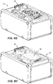
- FIGS. 9A-9F illustrates one example of a manufacturing process for the battery pack assembly 10 of FIG. 1 .
- step one with reference to FIG. 9A , the battery cells 90 and the battery cell holder (i.e., body portion 34) are provided. Each of the battery cells 90 is received in (e.g., pushed into) the battery cell holder 34.
- step two with reference to FIG. 9B , the battery strap 94 is secured (e.g., by welding) to the ends of each of the battery cells 90.
- the PCB 138 is secured (e.g., by welding) to the upper surface 182 of the body portion 34.
- step four with reference to FIG.
- the top housing portion 50 (having the injection port 18) is positioned on the body portion 34 of the bottom housing portion 54.
- the first and second side portions 42, 46 are positioned on the first and second sides of the body portion 34.
- Fasteners e.g., screws 186; FIG. 4
- the fluid is injected into the internal cavity 86 of the housing 30 using the injection port 18.
- a tube 190 is aligned with the injection axis 170 of the channel 158, and the fluid is directed through the tube 180 into the channel 158. As such, the fluid is received in the internal cavity 86 by a single injection of the fluid.
- the bottom housing portion 54 is assembled first (e.g., the body portion 34 and the first and second side portions 42, 46 are coupled together), and some of the fluid is received in (e.g., injected into) the bottom housing portion 54 ( FIG. 9G ) before the top housing portion 50 is coupled to the bottom housing portion 54.
- the remaining fluid is then received in the internal cavity 86 of the completed assembly using the injection port 18 of the top housing portion 50.
- FIG. 9H illustrates the fluid positioned within the internal cavity 86 after the remaining fluid is received in the internal cavity 86 and the top housing portion 50 is decoupled from the bottom housing portion 54. As such, the fluid is received in the internal cavity 86 by at least two injections of the fluid.
- the battery pack 14 is completely assembled (i.e., by steps one through five in FIGS. 9A-9E ), and then the battery pack 14 is positioned within a vacuum, before initiating step six of injecting the fluid into the internal cavity 86 of the battery pack 14 (FIG. 9F).
- the adhesive material is configured to be thermally conductive.
- Table 2 a thermal test of multiple battery packs was tested at three different discharges: 40A, 50A, and 60A.
- Temperature sensors T1-T6 were positioned at six different locations, respectively, within the back pack: T1 positioned on the upper surface 182 of the body portion 34 proximate one end of the PCB 138, T2 position on the upper surface 182 of the body portion 34 proximate the opposite end of the PCB 138 having the battery contacts 98, T3-T5 are positioned on the ends of respective battery cells 90, and T6 is positioned on the bottom side 82 of the housing 30. Each the temperature sensor determines a temperature reading at the respective location.
- the battery packs 14 with adhesive material (e.g., battery packs 3# and 4#) has an overall lower temperature at each of the six locations during discharging of the respective battery pack 14 in comparison to the battery packs without adhesive material.
- the battery packs 14 with adhesive material facilitates thermal conduction of heat away from the battery cells 90 and battery cell holder 34 as the battery cells 90 are being discharged. Accordingly, the adhesive material may increase thermal performance of the battery pack 14, which thereby may improve battery pack cycle life and cycle running time.
- Table 2 Test results of thermal testing of battery packs with and without adhesive material at three different discharges: 40A, 50A, and 60A.
- the adhesive material is configured to inhibit ingress of water and/or moisture, and/or increase a strength of the battery pack housing 30. More specifically, the adhesive material is configured to form a barrier between the battery pack components (battery cells 90, PCB 138, etc.) and exterior of the housing 30. As such, water and/or moisture is inhibited from reaching the internal cavity 86 of the battery pack housing 30.
- the adhesive material is also configured to eliminate space between various structures/components contained in the battery pack 14, and couple the battery pack components to the inner surfaces of the housing 30, as well as to each other. As such, the strength of the housing 30 increased (e.g., such as if the battery pack 14 is dropped).
- the adhesive material is configured to withstand a temperature range between -50 °C to 200 °C, is not configured to shrink during curing, and/or is configured to be noncorrosive.
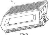
- FIG. 10 illustrates another example of a battery pack 14' of the battery pack assembly 10 that may include like component and features as the embodiment of the battery pack 14 shown in FIGS. 1-9F above. Accordingly, the discussion of the battery pack assembly 10 above similarly applies to the battery pack 14 and is not re-stated.
- the battery pack 14' may include the injection port 18 having the one or more channels 158 configured to direct the fluid into an internal cavity of the battery pack 14.
Landscapes
- Chemical & Material Sciences (AREA)
- Chemical Kinetics & Catalysis (AREA)
- Electrochemistry (AREA)
- General Chemical & Material Sciences (AREA)
- Engineering & Computer Science (AREA)
- Manufacturing & Machinery (AREA)
- Microelectronics & Electronic Packaging (AREA)
- Life Sciences & Earth Sciences (AREA)
- Biophysics (AREA)
- Computer Hardware Design (AREA)
- Battery Mounting, Suspending (AREA)
Applications Claiming Priority (1)
| Application Number | Priority Date | Filing Date | Title |
|---|---|---|---|
| CN202011411151.8A CN114597559A (zh) | 2020-12-04 | 2020-12-04 | 电池组 |
Publications (1)
| Publication Number | Publication Date |
|---|---|
| EP4012829A1 true EP4012829A1 (de) | 2022-06-15 |
Family
ID=78806392
Family Applications (1)
| Application Number | Title | Priority Date | Filing Date |
|---|---|---|---|
| EP21210838.5A Pending EP4012829A1 (de) | 2020-12-04 | 2021-11-26 | Batteriepack |
Country Status (3)
| Country | Link |
|---|---|
| US (2) | US11978916B2 (de) |
| EP (1) | EP4012829A1 (de) |
| CN (1) | CN114597559A (de) |
Cited By (1)
| Publication number | Priority date | Publication date | Assignee | Title |
|---|---|---|---|---|
| WO2024212161A1 (en) * | 2023-04-13 | 2024-10-17 | Techtronic Cordless Gp | Battery pack and its manufacturing method |
Families Citing this family (11)
| Publication number | Priority date | Publication date | Assignee | Title |
|---|---|---|---|---|
| EP4746129A3 (de) | 2020-12-04 | 2026-07-29 | Milwaukee Electric Tool Corporation | Batteriepack |
| CN220627729U (zh) | 2022-06-27 | 2024-03-19 | 米沃奇电动工具公司 | 熔断器及包括用于通过电流的导电路径的装置 |
| US20240186638A1 (en) * | 2022-12-06 | 2024-06-06 | Milwaukee Electric Tool Corporation | Battery pack assembly |
| DE102023112943A1 (de) * | 2023-05-16 | 2024-11-21 | Kautex Textron Gmbh & Co. Kg | Batteriegehäuse zur Aufnahme von einer Vielzahl von Batteriekomponenten, Batterie mit einem Batteriegehäuse und Batteriesystem mit einem Kühlfluidvorratsbehälter und einer Wärmetauschereinrichtung |
| CN119069908A (zh) * | 2023-05-31 | 2024-12-03 | 南京泉峰科技有限公司 | 电动工具及电池包 |
| USD1130292S1 (en) * | 2023-09-08 | 2026-06-16 | Milwaukee Electric Tool Corporation | Battery pack |
| USD1135810S1 (en) * | 2024-10-31 | 2026-07-21 | Shenzhen Mammotion Innovation Co., Limited | Battery pack |
| USD1122188S1 (en) * | 2025-04-18 | 2026-04-14 | Shenzhen Jinjunye Electronics Co., Ltd. | Power tool battery |
| USD1130294S1 (en) * | 2025-04-30 | 2026-06-16 | Changlin Song | Lithium battery |
| USD1122189S1 (en) * | 2025-05-12 | 2026-04-14 | Shenzhen Jinjunye Electronics Co., Ltd. | Power tool battery |
| USD1127704S1 (en) * | 2025-05-26 | 2026-05-26 | Shenzhen Jinjunye Electronics Co., Ltd. | Power tool battery |
Citations (3)
| Publication number | Priority date | Publication date | Assignee | Title |
|---|---|---|---|---|
| WO2016178315A1 (ja) * | 2015-05-07 | 2016-11-10 | 三洋電機株式会社 | 電池パック及び電池パックの製造方法 |
| US20180166736A1 (en) * | 2015-04-15 | 2018-06-14 | Lg Chem, Ltd. | Method of manufacturing embedded type battery pack using hot-melt fixing structure and battery pack manufactured using the same |
| EP3671895A1 (de) * | 2018-03-13 | 2020-06-24 | Lg Chem, Ltd. | Batteriemodul, batteriepack mit dem batteriemodul und fahrzeug mit dem batteriepack |
Family Cites Families (16)
| Publication number | Priority date | Publication date | Assignee | Title |
|---|---|---|---|---|
| US6455186B1 (en) | 1998-03-05 | 2002-09-24 | Black & Decker Inc. | Battery cooling system |
| US8617730B2 (en) * | 2010-09-30 | 2013-12-31 | Honda Motor Co., Ltd. | Battery for electric vehicle |
| WO2013013183A1 (en) | 2011-07-20 | 2013-01-24 | Milwaukee Electric Tool Corporation | Multi-bay battery charger |
| KR101433666B1 (ko) * | 2012-02-07 | 2014-08-25 | 주식회사 엘지화학 | 전지케이스 상의 미코팅 구간을 포함하는 전지셀의 제조방법 |
| US20150044519A1 (en) | 2012-03-19 | 2015-02-12 | Husqvarna Ab | Battery pack thermal management system |
| TWI514644B (zh) | 2013-09-25 | 2015-12-21 | Uer Technology Corp | 電池模組 |
| DE102014221684A1 (de) | 2014-07-11 | 2016-01-14 | Robert Bosch Gmbh | Gehäuse zur Aufnahme einer Vielzahl von Batteriezellen mit einer im Gehäuse integrierten Kühlungsvorrichtung |
| DE102015206392A1 (de) * | 2015-04-10 | 2016-10-13 | Robert Bosch Gmbh | Verfahren und Vorrichtung zum Temperieren von Batteriezellen sowie Fahrzeug |
| US10797285B2 (en) * | 2016-04-03 | 2020-10-06 | Cummins Battery Systems North America Llc | Battery pack including plural electrochemical cells encapsulated by encapsulant and method of manufacture |
| CN106784496B (zh) | 2017-01-25 | 2020-03-06 | 友达光电股份有限公司 | 电池模块 |
| CN112334542B (zh) * | 2018-06-27 | 2023-02-21 | 美国陶氏有机硅公司 | 热间隙填料及其在电池管理系统中的应用 |
| US11145932B2 (en) * | 2018-09-24 | 2021-10-12 | Milwaukee Electric Tool Corporation | Battery cell module and battery pack |
| CN109873104B (zh) * | 2018-12-13 | 2024-04-16 | 宁德时代新能源科技股份有限公司 | 电池模组 |
| CN210516810U (zh) | 2019-10-28 | 2020-05-12 | 中车资阳机车有限公司 | 一种独立内循环通风冷却的机车用动力蓄电池室模块 |
| CN211629166U (zh) | 2020-02-17 | 2020-10-02 | 浙江动一新能源动力科技股份有限公司 | 一种电池组件 |
| EP4746129A3 (de) | 2020-12-04 | 2026-07-29 | Milwaukee Electric Tool Corporation | Batteriepack |
-
2020
- 2020-12-04 CN CN202011411151.8A patent/CN114597559A/zh active Pending
-
2021
- 2021-11-26 EP EP21210838.5A patent/EP4012829A1/de active Pending
- 2021-12-02 US US17/540,621 patent/US11978916B2/en active Active
-
2024
- 2024-04-04 US US18/626,707 patent/US20240250361A1/en active Pending
Patent Citations (3)
| Publication number | Priority date | Publication date | Assignee | Title |
|---|---|---|---|---|
| US20180166736A1 (en) * | 2015-04-15 | 2018-06-14 | Lg Chem, Ltd. | Method of manufacturing embedded type battery pack using hot-melt fixing structure and battery pack manufactured using the same |
| WO2016178315A1 (ja) * | 2015-05-07 | 2016-11-10 | 三洋電機株式会社 | 電池パック及び電池パックの製造方法 |
| EP3671895A1 (de) * | 2018-03-13 | 2020-06-24 | Lg Chem, Ltd. | Batteriemodul, batteriepack mit dem batteriemodul und fahrzeug mit dem batteriepack |
Cited By (1)
| Publication number | Priority date | Publication date | Assignee | Title |
|---|---|---|---|---|
| WO2024212161A1 (en) * | 2023-04-13 | 2024-10-17 | Techtronic Cordless Gp | Battery pack and its manufacturing method |
Also Published As
| Publication number | Publication date |
|---|---|
| US20220181734A1 (en) | 2022-06-09 |
| CN114597559A (zh) | 2022-06-07 |
| US11978916B2 (en) | 2024-05-07 |
| US20240250361A1 (en) | 2024-07-25 |
Similar Documents
| Publication | Publication Date | Title |
|---|---|---|
| US11978916B2 (en) | Battery pack | |
| EP4256643B1 (de) | Batteriepack | |
| AU2014301796B2 (en) | Battery pack,tool battery and battery operated tool | |
| US7846577B2 (en) | Battery pack | |
| US9786877B2 (en) | Battery pack of electric power tool | |
| US20140093753A1 (en) | Battery pack including an electric harness and method of manufacturing the same | |
| EP3823081A1 (de) | Verfahren zur herstellung eines batteriepacks | |
| KR101944957B1 (ko) | 배터리 팩 및 이를 포함하는 자동차 | |
| KR102729947B1 (ko) | 배터리 팩 | |
| KR101481198B1 (ko) | 전지모듈 및 이를 포함하는 리튬이차 전지팩 | |
| CN220138625U (zh) | 电池包以及用电装置 | |
| KR20220099369A (ko) | 배터리 모듈 외곽 하우징 | |
| KR20170103227A (ko) | 배터리 모듈의 절연 물질 형성 방법 및 이를 위한 시스템 | |
| KR100601510B1 (ko) | 파우치형 리튬 이차 전지 및 그의 제조 방법 | |
| US20220115749A1 (en) | Battery pack | |
| KR102812956B1 (ko) | 배터리 모듈 | |
| CN115051096A (zh) | 电池组 | |
| CN118899613A (zh) | 具有可再充电的电化学储能元件的电池 | |
| EP4695865A1 (de) | Batteriepack und herstellungsverfahren dafür | |
| KR102856144B1 (ko) | 배터리 팩 및 이를 포함하는 자동차 | |
| CN221596686U (zh) | 一种2串1并加装保护电路手电筒锂电池 | |
| WO2024212178A1 (en) | Battery pack | |
| JP2025517507A (ja) | 電池モジュールケースおよびこれを含む電池モジュール | |
| KR20230165702A (ko) | 전지 모듈 케이스 및 이를 포함하는 전지 모듈 | |
| CN119256439A (zh) | 电池模块及用于制造该电池模块的方法 |
Legal Events
| Date | Code | Title | Description |
|---|---|---|---|
| PUAI | Public reference made under article 153(3) epc to a published international application that has entered the european phase |
Free format text: ORIGINAL CODE: 0009012 |
|
| STAA | Information on the status of an ep patent application or granted ep patent |
Free format text: STATUS: REQUEST FOR EXAMINATION WAS MADE |
|
| 17P | Request for examination filed |
Effective date: 20211126 |
|
| AK | Designated contracting states |
Kind code of ref document: A1 Designated state(s): AL AT BE BG CH CY CZ DE DK EE ES FI FR GB GR HR HU IE IS IT LI LT LU LV MC MK MT NL NO PL PT RO RS SE SI SK SM TR |
|
| STAA | Information on the status of an ep patent application or granted ep patent |
Free format text: STATUS: EXAMINATION IS IN PROGRESS |
|
| 17Q | First examination report despatched |
Effective date: 20260112 |